50P FLEX - Compressor POWERNAIL - Free user manual and instructions
Find the device manual for free 50P FLEX POWERNAIL in PDF.

User questions about 50P FLEX POWERNAIL
0 question about this device. Answer the ones you know or ask your own.
Ask a new question about this device
Download the instructions for your Compressor in PDF format for free! Find your manual 50P FLEX - POWERNAIL and take your electronic device back in hand. On this page are published all the documents necessary for the use of your device. 50P FLEX by POWERNAIL.
USER MANUAL 50P FLEX POWERNAIL
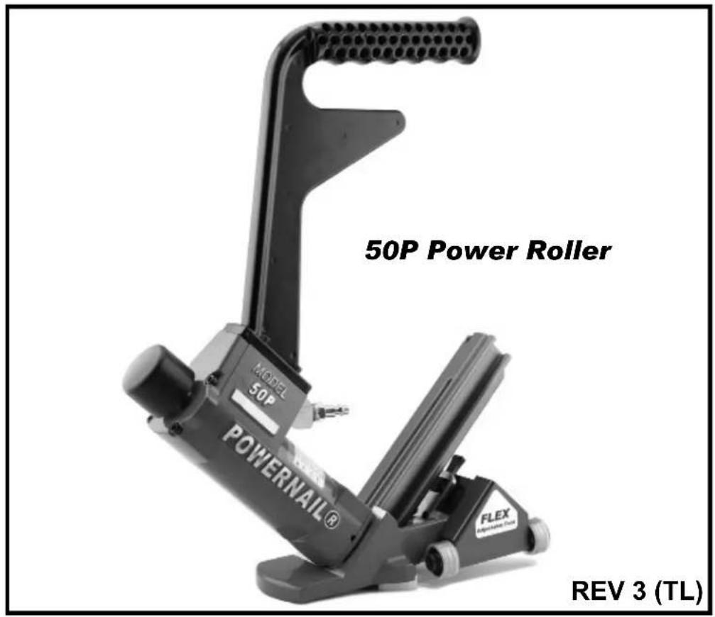
Powernail® 50P FLEX with Power Roller
text_image
50P Power Roller MODEL 50P POWERNAIL® FLEX REV 3 (TL)OPERATION AND MAINTENANCE MANUAL MANUAL DE OPERACION Y DE MANTENIMIENTO MANUEL D'INSTRUCTIONS ET D'ENTRETIEN
WARNING

Read this manual before you use this Powernailer®. Follow all safety warnings and instructions. If you are uncertain about the operation of the nailer, call us directly at 1-800-323-1653 for assistance or contact the closest Powernail Dealer for help. Please retain this information for future reference.
INTRODUCTION
The Powernail FLEX Power Roller Pneumatic Nailer is designed to bring Powernail quality to a pneumatic nailer. For those looking for the ease of use of a pneumatic tool, the Powernail FLEX Power Roller is designed for use with only 1", 1-1/4", 1-1/2" and 1-3/4" (18 gauge) Powercleats® nails.
The Powernail FLEX Power Roller is recommended for use on thinner 3/8", 1/2", 5/8" and 3/4" solid tongue and groove hardwood as well as some other hard exotics, bamboo, and engineered woods.
For a superior pneumatic Nailer, look to the company that has been the industry's quality leader, POWERNAIL® COMPANY, INC.
INDEX
Index...... 2
Warranty.... 2
Safety Instructions.... 3
Powernail Company Info..... 3
Operating Instructions...... 4-8
Parts & Service...... 5-8
Drive Blade.... 6
Seal Replacement...... 6-7
Safety Labels...... 8
Parts List.... 9-11
Seal Locations Diagram..... 12
Schematic 13
Depth Chart.... 14
Troubleshooting Chart...... 15
LIMITED WARRANTY
POVERNAIL® Company, Inc. warrants to its customer, and to the first end-use purchaser of POWERNAIL flooring nailers purchased from an authorized POWERNAIL distributor, that each serialized manufactured nailer by POWERNAIL®, for a period of 12 months from the date of purchase, and with respect to the nailer body (specifically Models 200, 445, and 50P), for a period of 10 years from date of purchase, (“warranty period”); shall be free of defects in materials and workmanship and will meet POWERNAIL’s specifications in effect at the time of Product shipment. POWERNAIL will repair or replace, at its option, any Powernailer® that does not conform to this warranty. Claims must be made no later than fifteen (15) days after the end of the warranty period. POWERNAIL will perform all repair or replacements itself or through its authorized contractors. POWERNAIL is not responsible for shipping, labor or other direct or indirect costs. Damage caused by abuse, misuse, unusual or excessive wear is excluded. Repair or modification of the Products by unauthorized parties will void this warranty. The customer is responsible for returning Products to POWERNAIL for verification of nonconformance. Warranties for Products not manufactured by POWERNAIL are limited to warranties provided to POWERNAIL by the manufacturer of such product that are assignable to customer.
THESE WARRANTIES AND REMEDIES ARE EXCLUSIVE OF ALL OTHERS, EXPRESS OR IMPLIED. THE WARRANTIES OF MERCHANTABILITY AND FITNESS FOR PURPOSE ARE EXPRESSLY EXCLUDED. IN NO EVENT SHALL POWERNAIL'S LIABILITY FOR A WARRANTY CLAIM EXCEED THE PRICE PAID TO POWERNAIL FOR THE NONCONFORMING PRODUCT, REGARDLESS OF THE FORM OR BASIS OF THE CLAIM OR CAUSE OF ACTION.
POWERNAIL COMPANY, INC.
1300 Rose Road, Lake Zurich, IL 60047 US
Phone: 1-800-323-1653 OR 847-847-3000
www.powernail.com
SAFETY INSTRUCTIONS

Always use approved SAFETY GLASSES and EAR PROTECTION when operating this Nailer. The operator and others in the work area should always wear approved FRONT and SIDE eye protection when operating this Nailer. Eye protection will help guard against flying nails and debris, which could cause severe eye injury.

EYE AND EAR PROTECTION should be used to prevent hearing damage when there are high noise levels in the work area.
ALWAYS use ear plugs with a noise reduction rated at 29 db or higher at a construction site.
Nailer noise ratings are at LPA-1sd=90.6,
LWA-1sd=99.3 and LPA-1s,1m=86.3.
Nailer vibration rating: m/s2=3.05.
Always DISCONNECT THE AIR SUPPLY before making any adjustments, repairing, clearing jams or when the Nailer is not in use. Do not use on scaffolding or ladders and disconnect nailer from air supply when transporting between installation areas.
Never attach the female end of a quick disconnect to the Nailer. This will trap air inside the Nailer and permit it to be discharged. Only the unrestricted male connection should be attached to the Nailer.
Nailer requires an air source that can continuously deliver 80 to 110 psi at 3-1/2 cubic feet of air per minute for operation.
Normal air pressure should not exceed 120 psi or damage to the Nailer and seals may occur. Excess air pressure can cause the Nailer to explode.
To prevent fire or explosion, use only regulated compressed air—do not use bottled gases of any kind (no oxygen or combustible gasses) to power this Nailer.
Nailer is intended for use installing wood flooring and is not to be used for purposes not specified in the operations manual.
Do not use any nails other than Powernail Powercleats Nails which are specifically designed for use in any Powernailer. Powercleats Nails are available in various lengths. Contact your Powernail Dealer for Powercleats Nails.
Use only Powernail replacement parts in the repair or maintenance of this nailer. Parts or repair services are available from the manufacturer or from agents authorised by the manufacturer. Repairs should be carried out only by trained service personnel in the field of fastener driving tools who will observe proper safety controls while performing maintenance. Service personnel should be qualified to to assess the safe working condition of fastener driving tools.
Never place any part of the body in the discharge path of the Nailer when air is connected to the Nailer. Always make sure Nailer is empty of cleats before connecting air hose so as to prevent any accidental discharge from occurring.
Never leave the Nailer unattended while it is connected to an air supply.

Whenever air is connected to the Nailer, keep body parts away from the nail discharge path. Disconnect the air line before making adjustments or repairs on the Nailer. Only connect air to an unloaded Nailer so as to prevent accidental discharge.

Nailer is activated by striking the plunger. Do not work on scaffolding, ladders, elevated or uneven surfaces where the nailer could fall and self-activate. Do not leave air attached to the Nailer when moving from one install location to another.
OPERATION
Read these instructions carefully before you use the Nailer.
To use the Powernail Flex, adjust the nailer FLEX foot to a sample of your flooring (see instructions below).
When the nailer foot is adjusted to your flooring, simply place the nailer on the floor and pull nailer back so the triangle & 9mm roller (Figure 2) catch the edge of the floor above the tongue. Hit the plunger with the rubber-capped mallet-end to let the Nailer drive and set the nail at the correct 45 degree angle.
FLEX Foot Adjustment:
Wood varies from one manufacturer to the next. The different wood profi les may be due to height and length of the fl ooring tongue and whether or not there is a nail pocket.
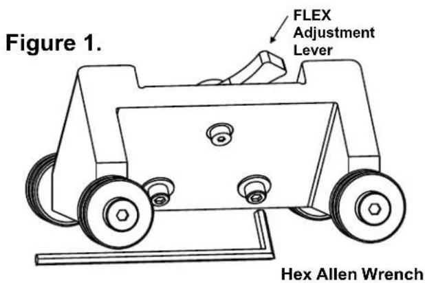
First, loosen the two hex bolts under the FLEX foot with the Allen Wrench supplied with the nailer. (Figure. 1.)
Using 2-3 sample boards of your flooring, set the nailer on the boards with the 4 large rollers flat on the floor and the triangle & 9mm roller sitting on or above the tongue.
Use the FLEX adjustment lever (Figure 1) at the back of the nailer foot to raise the triangle & 9mm roller above the flooring tongue. There should always be a gap between the tongue and the triangle & 9mm to avoid unnecessary wear (Figure 2).
When the setting is correct for your wood sample, tighten the two hex bolts to lock the FLEX foot into place.
Always test-nail a wood sample to ensure the nail is driving into the nail pocket at the back of the flooring tongue.
Figure 2.
Raise the nailer foot to leave a small gap between the triangle & 9mm roller and the fl ooring tongue.
Loading Top Load Channel:
To Load the Powernail Flex:
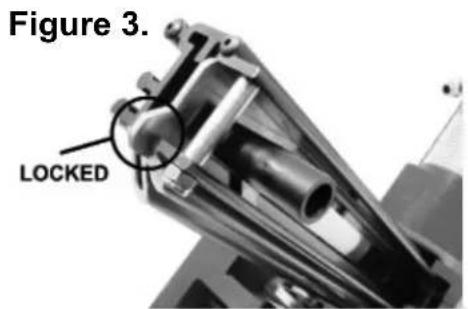
Pull back the spring loaded nail pusher towards the end of the channel until the pusher plate locks (Figure 3). Place up to one stick (100) of Powercleats® (18-gauge) nails, 1", 1-1/4", 1-1/2" or 1-3/4" long into the nail feed slot located on the top of the channel (Figure 4). Release nail pusher from locked position and gently guide it down until it meets the end of the cleat strip (Figure 5.
To Unload
Pull back the spring loaded nail pusher towards the end of the channel until the pusher plate locks. Then turn the nailer over so so that the nails slide out of the top nail feed slot.
text_image
Figure 1. FLEX Adjustment Lever Hex Allen Wrench- Loosen 2 hex screws.
- Raise or lower the FLEX to your wood sample.
- Match the triangle & 9mm roller to the nail pocket.
- Tighten 2 hex screws.
- Test wood sample with new adjustment.

natural_image
Close-up of a mechanical assembly with visible components and no readable text or symbols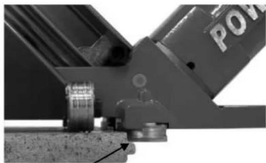
natural_image
Close-up of a mechanical assembly with a labeled component (no readable text or symbols)Adjust FLEX lever so the triangle & 9mm roller is above the flooring tongue
OPERATION, continued...
text_image
Figure 3. LOCKED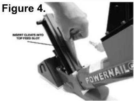
text_image
Figure 4. INSERT CLEATS INTO TOP FEED SLOT POWERNAIL®
text_image
Figure 5. GENTLY RELEASE PUSHER FROM LOCKED POSITION AND GUIDE IT TO THE END OF THE CLEAT STRIP POWERNAIL®WARNING: It is not necessary to hit the Nailer hard to activate it. Never hit the Nailer with excessive force or with the metal end of the mallet, this will damage the Nailer.
Before each use check all screws to be sure they are tight. Shock and vibration can loosen screws. Do not over tighten any screw.
AIR SUPPLY:
The air must be clean and dry. Dirty and/or wet air will damage the Nailer. A combination fi Iterregulator-lubricator is required for proper Nailer performance and should be placed close to the Nailer per manufacturer's recommendations.
The air source must continuously deliver 80 to 110 psi at 3-1/2 cubic feet of air per minute to operate the Nailer. Connect a clean air hose and air regulator to the Nailer.
Check for air supply leaks that waste air and starve the Nailer of air thereby reducing its performance.
LUBRICATION:
If you do not use an in line lubricator, you must lubricate the Nailer manually. The frequency of lubrication is dependent upon the duty cycle of the Nailer. Continuous duty requires more frequent oiling than intermittent duty.
At least every eight (8) hours place two to four drops of Pneumatic Light Air Tool Oil into the disconnected air line male connector attached to the Nailer. WARNING: Detergent oil is not recommended and may damage the seals.
WARNING: Do not over lubricate the Nailer, excess oil mist or drops will be vented with spent air when over lubricated. Excess oil could stain the wood flooring, walls or furnishings. Dry fi re the Nailer, without nails, to purge excess oil, before you begin to nail down flooring. We will not be responsible for oil stains. Before storing the Nailer, lubricate and cycle the Nailer in insure internal parts are oil protected from corrosion.
PARTS & SERVICE:
When ordering parts include the part number, part description, Powernailer model and serial number. Be sure to state the quantity of the part(s) required. Contact your Powernail Dealer for the necessary parts or service.
WARNING: Never work on the Nailer if the air line is attached. Always disconnect the air line from the Nailer first.
NAILER DISASSEMBLY:
TO REPLACE RUBBER BUMPER (#24):
- Disconnect the air supply
- Remove the four (4) cap screws holding the Adapter Foot, Foot and Nail Channel assembly to the main Body.
- Pull the Rubber Bumper out of the cylinder bore. Replace the old Bumper if it shows signs of wear or it is split.
- Reverse these steps to reassemble the Nailer. Be sure to align the Driving Blade with the slot in the Nail Channel Assembly while you reassemble the Nailer. NEVER FIRE THE NAILER WITHOUT THE RUBBER BUMPER INSTALLED, IT WILL DAMAGE THE NAILER.
OPERATION, continued...
TO REPLACE DRIVING BLADE(#15):
- Disconnect the air supply
- Remove the four socket head cap screws holding the Adapter Foot, Foot and Nail Channel Assembly to the body.
- Remove the Rubber Bumper
- Pull the Driving Blade with pliers until the Piston is fully extended outward towards the bottom of the cylinder.
- Use a 15/16" box wrench (Part #: 09-44529768) to unscrew the Driving Blade Jam Nut and remove it. Hold the Piston from turning while unscrewing the Jam Nut by holding the piston hex with a 1-1/8" box wrench (Part #: 09-44529768).
- Push out the 1/4" diameter blade retaining Dowel Pin and remove the broken Driving Blade stub.
- Install a new Driving Blade in the slot and replace the Dowel Pin. Screw on the retaining Jam Nut using the same tools. If the Jam Nut becomes worn and loose after frequent removals, it should be replaced.
- Check the fi t, there should be some sideways movement between the Driving Blade and the Jam Nut assembly. This is desirable and helps the blade to align itself with the mating parts.
- Reassemble the components. Be sure to align the Driving Blade with the slot in the Adapter Foot Assembly, it goes in only one way.
SEAL REPLACEMENT:
There are 7 seals that may require replacement. We recommend that you have your POWERNAIL Dealer replace the Seals.
SEAL KIT:
You may choose to buy a Seal Replacement Kit and replace the seals yourself. It is good practice to replace all seals at one time regardless if only one seal needs replacement.
SEAL DESCRIPTION & NUMBER:
- Piston U cup Lip Seal (#21)
-
Return Cylinder U cup Lip Seal (#17)
-
Piston Rod U cup Lip Seal (#12)
- Rubber Seat (#18)
- Plunger Seal Set (#10)
- Plunger Wiper Seal (#4)
- Return Cylinder 0 Ring Gasket (#11)
To change Seals follow these procedures. Be sure the air line is disconnected from the Nailer first before making any repairs. Consult the illustration for the name and location of the following component parts.
SEAL REPLACEMENT REQUIRES REMOVAL OF THE DRIVING BLADE ASSEMBLY:
- Disconnect the air supply.
- Remove Rubber Plunger Cap (#7).
- Unscrew & remove Body Cap (#2).
Unscrew the three 10-32 cap screws holding the Plunger (#9) to the Return Cylinder (#16). - Pull the Plunger up and out of the Nailer Body (#1) cavity.
-
Remove the Return Cylinder 0 Ring Gasket (#11) located on the top of the Return Cylinder under the Plunger.
-
Turn the Nailer over and remove the four foot screws (#45), that fasten the Adapter Foot and Nail Channel Assembly to the Nailer Body and lift the Assembly off the Body.
-
Remove the Rubber Bumper (#24).
-
Pull the Driving Blade Assembly out of the Nailer Body by pulling on the Driving Blade.
-
Hold the Piston Rod (#13) with an 11/16" socket over its hex end opposite the Piston. Do not use pliers or a vise anywhere on the metal parts, they can damage the sealing surfaces.
-
Use box wrenches to remove the 5/8-18 Jam Nut (#22). Remove the Dowel Pin (#14) and Driving Blade (#15).
- Unscrew the Piston from the Piston Rod using box wrenches and separate the Piston, Piston Rod and
OPERATION, continued...
Return Cylinder.
TO REPLACE THE SEALS:
Plunger Seal Set (#10):
- Remove the Tefl on ^® Seal and its O-ring expander from the Plunger groove using a bent paper clip or pick. Be sure not to scratch the inside walls of the seal groove with the wire hook.
- Clean out the seal groove. Place a new O-ring into the seal groove by stretching it over the Plunger body. Make sure the O-ring is not twisted in the groove. Place a new Tefl on Seal Ring into the seal groove over the O-ring.
- Carefully push the Tefl on® Seal Ring over the edge of the Plunger with your thumbs and into the groove. Do this as quickly as possible to reduce stretching of the Tefl on® Seal Ring. DO NOT OVER STRETCH THE TEFLON® SEAL RING. Be sure the Tefl on® Seal Ring is centered all around the seal groove and not twisted.
- Wipe off the Seal surface with a clean rag and lubricate it generously with Pneumatic Light air tool oil lubricant.
Rubber Seat (#18):
- Remove the Cylinder Sleeve (#23). The Cylinder Sleeve would slide out of the Nailer Body when you pull out the Driving Blade
- Remove the metal Support Ring (#19) and Rubber Seat from inside the Nailer body. NOTE THAT THE CHAMFER ON THE INSIDE OF THE RUBBER SEAT FACES THE BOTTOM OF THE NAILER. Do not reverse the direction of the chamfer when you replace the Rubber Seat.
- Replace the Rubber Seat, Support Ring and Cylinder Sleeve. Be sure to re install the steel Cylinder Sleeve with the chamfered inside edge facing the BOTTOM of the Nailer.
Piston U Cup Lip Seal (#21):
-
Remove the old Piston U Cup Lip Seal from the Piston using a bent paper clip or pick, being careful not to scratch the inside walls of the seal groove or the edge of the Piston with the wire hook.
-
Clean out the seal groove. Place a new U-Cup Lip Seal into the groove. Make sure the lip seal is not twisted in the groove and the lips face the top of the Nailer. See the sketch on page 12.
- Carefully wipe off the U Cup Lip Seal surface with a clean rag and lubricate it generously with Pneumatic Light air tool oil lubricant.
Return Cylinder U Cup Lip Seal (#17):
- Use a bent paper clip or pick to remove the old U Cup Lip Seal from the internal seal groove inside the Return Cylinder. Be careful not to scratch the inside walls of the seal groove with the wire hook.
- Clean out the seal groove. Place a new U Cup Lip Seal into the groove, be sure it is not twisted in the groove. Be sure the lips are facing the inside of the Return Cylinder as shown on the Seal Placement sketch on page 12.
- Carefully wipe off the Lip Seal surface with a clean rag and lubricate it generously with Pneumatic Light air tool oil lubricant.
WARNING: The U-Cup Lip Seals #17 and #12 look alike, but they are different, DO NOT mix them up.
Piston Rod U-Cup Lip Seal (#12):
- Remove the old U-Cup Lip Seal from the seal groove with a bent paper clip or pick using care not to scratch the inside walls of the seal groove with the wire hook.
- Clean out the seal groove and install a new U-Cup Lip Seal. Be sure the Lips are facing the right direction and are not twisted in the groove. See the sketch on page 12.
- Carefully wipe off the seal surface with a clean rag and lubricate it generously with Pneumatic Light Air Tool Oil lubricant.
OPERATION, continued...
Plunger Wiper Metal Cap O-Ring (#4):
- Use a bent paper clip to pick out the Wiper Seal out of its groove in the Body Cap (#2).
- Clean out the groove and insert the new O-Ring (#4) in to the groove in the metal body cap (#2).
Return Cylinder O-Ring Gasket (#11):
- Place a new O-Ring Gasket in the groove on top of the Return Cylinder when you reassemble the Driving Blade Assembly.
- Wipe off the O-Ring Gasket seal surface and lubricate it generously with Pneumatic Light air tool oil lubricant.
- Be sure the Rubber Seat, Support Ring and Cylinder are installed in the Body and are facing the correct direction.
- All seal surfaces must be clean and lubricated generously with Pneumatic Light air tool oil lubricant.
Replace any part that shows signs of wear.
- Use care when installing the seals into their respective cavities. Be sure the Seals are contained in their groove and do not come out as the parts slide together. Generous cavity lead in chamfers have been provided to help Seal installation.
- Carefully insert the Piston Rod into the Return Cylinder and screw the Piston onto the rod. Be sure the Piston is facing the correct way, ears up, hex down.
- Assemble the Driving Blade, Dowel Pin and Jam Nut on to the Piston Rod.
- Insert the Driving Blade Assembly up into the bottom of the Nailer Body Cylinder.
- Be sure there is a new O-Ring Gasket in the top groove of the Return Cylinder.
For Step-by-Step Videos and Instructions, Visit our Web Site at: www.Powernail.com
- Insert the Plunger into the top cavity of the Body. Line up the holes and install the three Plunger retaining screws. It is important that the three #10-32 screws are tight or air leakage will occur. Our recommendation is to use 1-2 drops of blue Loctite® or similar on the 3 screws.
- Install the Body Cap and Plunger Rubber Cap.
- Turn the Nailer upside down. Install the Rubber Bumper, Nail Channel Assembly and Adapter Foot. Be sure to align up the Driving Blade with the slot in the Foot before the Nailer is closed up.
- NEVER FIRE THE NAILER WITHOUT THE RUBBER BUMPER INSTALLED, IT WILL DAMAGE THE NAILER BEYOND REPAIR.
TO CLEAR A NAIL JAM:
Simply remove the two 1/4 - 28 x 1/2" screws (#35) with a 3/16" Allen wrench.
Slide the Gate Plate (#29) down and lift out.
You can now clear and inspect the Drive Blade path.
To re-assemble: Replace the Gate Plate (#29) and two screws (#35) and tighten firmly.
NAILER SAFETY DECALS

Warning!

- Read and understand the tool labels and manuals before operating. • Operators and others in work area MUST wear EYE and EAR protection. • Use safety glasses with side shields. • NEVER point tool at yourself or others in the work area. • Only connect air to an unloaded tool and always keep tool pointed in a safe direction. • Disconnect air when clearing jams, servicing or when tool is not in use. • Use only clean, dry, regulated air not exceed 110 psi. • Never use oxygen or other bottled gasses-explosion may occur.


CAUTION:
Lubricate Nailer with 2-4 drops of Industrial Light Oil for every 8 hours of use.
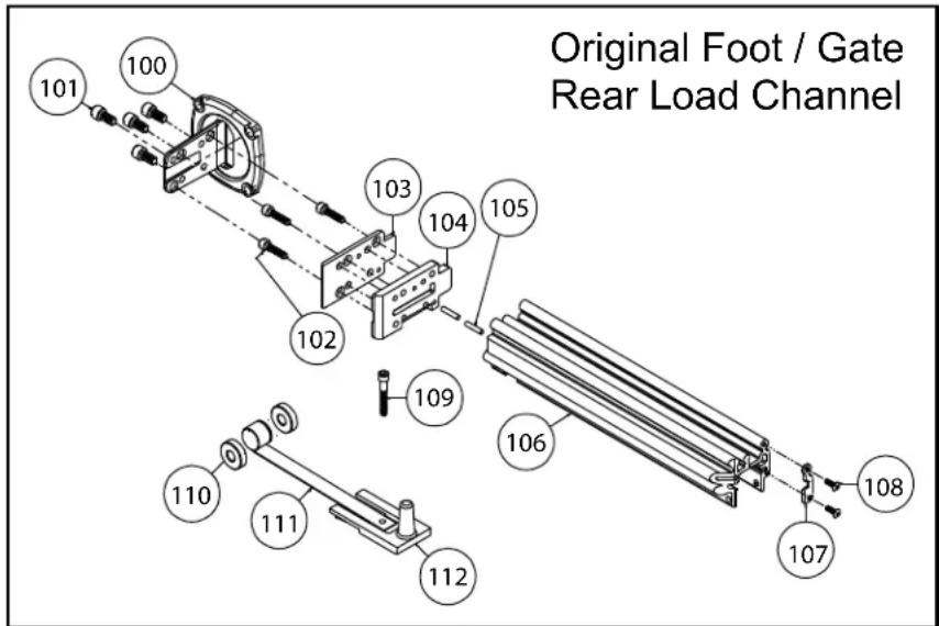
POWERNAIL 50P FLEX REAR LOAD CHANNEL AND ORIGINAL FOOT PARTS LIST
If your nailer was manufactured in or before 2017, you may have the rear load channel configuration and/or original foot, gate, and gate plate. These parts have since been revised but are still available as replacement parts. Please check your nailer to determine it's configuration before ordering parts.
| Item # | PART NO. DESCRIPTION | Qty Req'd | Sold Separate or Assembly # | |
| 100 | 09-50P3006 | FOOT (Original) | 1 | S, A-30 |
| 101 | 09-44529754 | #10-32 X 1/2" SHCS (FOOT) (Original) | 4 | S, A-30 |
| 102 | 09-44529822 | #10-32 X 3/4" SHCS w/patch (GATE) (Original) | 3 | S, A-30 |
| 103 | 09-50P3017 | GATE PLATE (Original) | 1 | S, A-30 |
| 104 | 09-50P3042 | GATE (Original) | 1 | S, A-30 |
| 105 | 09-44529741 | ROLL PIN (Original) | 1 | S, A-30 |
| 106 | 09-50P3008 | CHANNEL (Rear Load) | 1 | S, A-30 |
| 107 | 09-50P3040 | CHANNEL PLATE (Rear Load) | 1 | S, A-30 |
| 108 | 09-50P3041 | #6-32 X 3/8" BHCS (Channel Plate) (Original) | 1 | S, A-30 |
| 109 | 09-44529745 | #10-32 X 1-1/4" SHCS (Knob) (Rear Load) | 1 | S, A-30. A-31 |
| 110 | 09-2003035 SPOOL | 2 | S, A-30. A-31 | |
| 111 | 09-2003034 | NAIL PUSHER SPRING (Rear Load) | 1 | S, A-30. A-31 |
| 112 | 09-44529735 | NAIL PUSHER (Rear Load) | 1 | S, A-30. A-31 |
Powernail FLEX Assemblies, Kits
| ITEM PART NO. DESCRIPTION | QTY | |
| A-30 09 | 50P-3065A NAIL CHANNEL ASSEMBLY (Rear Load) 1 | |
| A-31 09 | 2003063A NAIL PUSHER ASSEMBLY (Rear Load) | 1 |
| 09-50PTUKIT Tune-up Kit for all (original) 50P, 50P FLEX, & 50P Power Rollers 1 | ||
text_image
Original Foot / Gate Rear Load ChannelFor this parts list and other Powernailer schematics, please visit the Powernail Parts Store at http://www.powernail.com
| ITEM # | PART NO. | DESCRIPTION QTY TU | SOLD SEPERATE OR ASSEMBLY / KIT # | ||
| 1 09-50P3001 BODY 1 F | |||||
| 2 09-50P3150 CAP (LOW PROFILE) 1 S | |||||
| 3 09-50P3202 1/4-20 X 5/8" S.H.C.S. W/ PATCH (COVER) 4 S | |||||
| 4 | 09-44529729 | PLUNGER WIPER METAL CAP O-RING | 1 | TU | S, A-1 |
| 5 09-44529759 3/8 NPT | 45 DEGREE STREET ELBOW | 1 S | |||
| 6 | 09-4455418 | 1/4" AIR FITTING 3/8" NPT | 1 | S | |
| 7 09-44529722 RUBBER CAP | TU | S | |||
| 8 | 09-44529832 #10-32 X 3/4" S.H.C.S. W/PATCH (PLUNGER) | 3 | S, A-6 | ||
| 9 09-50P3014 PLUNGER (LOW PROFILE) | S, A-6 | ||||
| 10 | 09-44529725 | PLUNGER SEAL SET | 1 | TU | S, A-1, A-6 |
| 11 | 09-44529731 | RETURN CYLINDER O-RING GASKET | 1 | TU | S, A-1, A-6 |
| 12 | 09-2003028 | PISTON ROD U-CUP LIP SEAL | 1 | TU | S, A-1, A-6 |
| 13 | 09-50P3010 PISTON ROD | 1 | S, A-6 | ||
| 14 | 09-44529740 | 1/4 X 1/2" DOWEL PIN (DRIVING BLADE) | 1 | TU | S, A-6 |
| 15 | 09-50P3018 | DRIVING BLADE | 1 | TU | S, A-6 |
| 16 09-2003013 RETURN CYLINDER | S, A-6 | ||||
| 17 | 09-2003027 | RETURN CYLINDER U-CUP LIP SEAL | 1 | TU | S, A-1, A-6 |
| 18 | 09-44529723 | RUBBER SEAT | 1 | TU | S, A-1, A-6 |
| 19 | 09-44529721 SUPPORT RING | 1 S | |||
| 20 | 09-2003011 | PISTON | 1 | S, A-6 | |
| 21 | 09-2003026 | PISTON U-CUP LIP SEAL | 1 | TU | S, A-1, A-6 |
| 22 | 09-44529748 | 5/8-18 JAM NUT (DRIVING BLADE) | 1 | TU | S, A-6 |
| 23 09-2003015 CYLIN DER SLEEVE | 1 S | ||||
| 24 | 09-44529724 | RUBBER BUMPER | 1 | TU | S |
| 25XL | 09-50P3201 | HANDLE, X-LONG | 1 | S | |
| 25L | 09-50P3200 | HANDLE, LONG | 1 | S | |
| 26 09-44529744 1/4-20 x 3/4" SHCS W/PATCH | 4 | S | |||
| 27L | 09-50P3058 | NAIL CHANNEL (TOP LOAD), LONG | 1 | S, A-20 | |
| 27S | 09-50P3056 | NAIL CHANNEL (TOP LOAD), SHORT | 1 | S, A-16 | |
| 28 | 09-50P3042R2 | GATE (Revision 2) | 1 | TU | S, A-14, A-16, A-20 |
| 29 | 09-50P3017R2 | GATE PLATE (Revision 2) | 1 | TU | S, A-14, A-16, A-20 |
| 30 | 09-50P3006R2 | STEEL FOOT (Revision 2) | 1 | S, A-14, A-16, A-20 | |
| 31 | 09-44529750 | #8-32 X 1-1/2" FHCS (SPACER) | 2 | S, A-16, A-20 | |
| 32 | 09-44529756 | 1/4 X 1" SPACER (CHANNEL) | 2 | S, A-16, A-20 | |
| 33 | 09-44529751 | #8-32 LOCKNUT (SPACER) | 2 | S, A-16, A-20 | |
| 34 | 09-50P3046 | 1/4-20 x 5/8" SHCS w/patch Torx Drive T27 (R2) | 2 | S, A-14, A-16, A-20 | |
| 35 | 09-50P3047 | 1/4-28 x 1/2" SHCS w/patch (R2 Gate Plate) | 2 | TU | S, A-14, A-16, A-20 |
| 36 | 09-50P3045 | #10-32 x 3/4" FHCS w/patch (R2 Gate) | 3 | TU | S, A-14, A-16, A-20 |
| 37 | 09-50P3050 | NAIL PUSHER (TOP LOAD) | 1 | S, A-9, A-15, A-16, A-20 | |
| 38 | 09-50P3054 | PUSHER PLATE (TOP LOAD) | 1 | S, A-15, A-16, A-20 | |
| 39 | 09-50P3057 | #10-32 x 1-1/2" SHCS (TOP LOAD) | 1 | S, A-15, A-16, A-20 | |
| 40 | 09-44529735.2 | NAIL PUSHER KNOB | 1 | S, A-9, A-15, A-16, A-20 | |
| 41 | 09-50P3055 | NAIL PUSHER SPRING (TOP LOAD) | 1 | S, A-9, A-15, A-16, A-20 | |
| 42 | 09-445297341 | SPOOL (TOP LOAD) | 2 | S, A-9, A-15, A-16, A-20 | |
KEY: S=Sold Separately, A= Sold as part of assembly, F=Factory replacement only
Powernail FLEX Assemblies, Kits and Accessories
| ITEM | PART NO. | DESCRIPTION | QTY | KEY |
| A-1 | 09-200-3058A | SEAL KIT (1 EACH OF ALL SEALS) | 1 | S |
| A-2 | 06-99605 | POWER ROLLER CONVERSION KIT | 1 | S |
| A-3 | 09-50P3106A | COMPLETE ROLLER SET W/TRIANGLE (4 LRG ROLLERS + 1 9MM ROLLER + TRIANGLE (PLASTIC)) | 1 | S |
| A-6 | 09-50P3064A | DRIVING BLADE ASSEMBLY W/RUBBER SEAT | 1 | S |
| A-7 | 09-AW445 | ALLEN WRENCH SET (3/16 & 5/32) | 1 | S |
| A-8 | 09-44529757A | 6 OZ. INDUSTRIAL LIGHT AIR TOOL OIL | 1 | S |
| A-9 | 09-2003063A | NAIL PUSHER ASSEMBLY | 1 | S |
| A-11 | 09-44529766 | 3/8" M & F COUPLING SET | 1 | S |
| A-12 | 09-44529768 BOX | WRENCH (2) | 2 | S |
| TU | 09-50PTUKITR2C | TUNE-UP KIT FOR ALL (R2) 50P, 50P FLEX, & 50P POWER ROLLERS | 1 | S |
| A-14 | 09-50PFOOTKIT | R2 FOOT ASSEMBLY, includes R2 Foot, Gate, Gate Plate, and Screws. | 1 | S |
| A-15 | 09-50P3050A | NAIL PUSHER ASSEMBLY (TOP LOAD) | 1 | S |
| A-16 | 09-50P3056A | NAIL CHANNEL ASSEMBLY (TOP LOAD) | 1 | S |
| A-20 | 09-50P3061A | LONG CHANNEL ASSEMBLY (TOP LOAD) | 1 | S |
| 09-50P3107 TRI-GLIDE TRIANGLE (ALUMINIUM) | 1 | S | ||
SEAL PLACEMENT

text_image
SEAL P/N & LOCATION #4 PLUNGER WIPER SEAL #09-445-29729 #12 PISTON ROD U-CUP SEAL #09-200-3028 INSTALL AS SHOWN #17 RETURN CYLINDER U-CUP SEAL #09-200-3027 INSTALL AS SHOWN #21 PISTON U-CUP SEAL #09-200-3026 INSTALL AS SHOWN #11 RETURN CYLINDER O-RING GASKET #09-445-29731 #10 PLUNGER SEAL #09-445-29725 #18 RUBBER SEAT #09-445-29723 INSTALL AS SHOWN DRIVING BLADESCHEMATIC - 50P FLEX POWER ROLLER
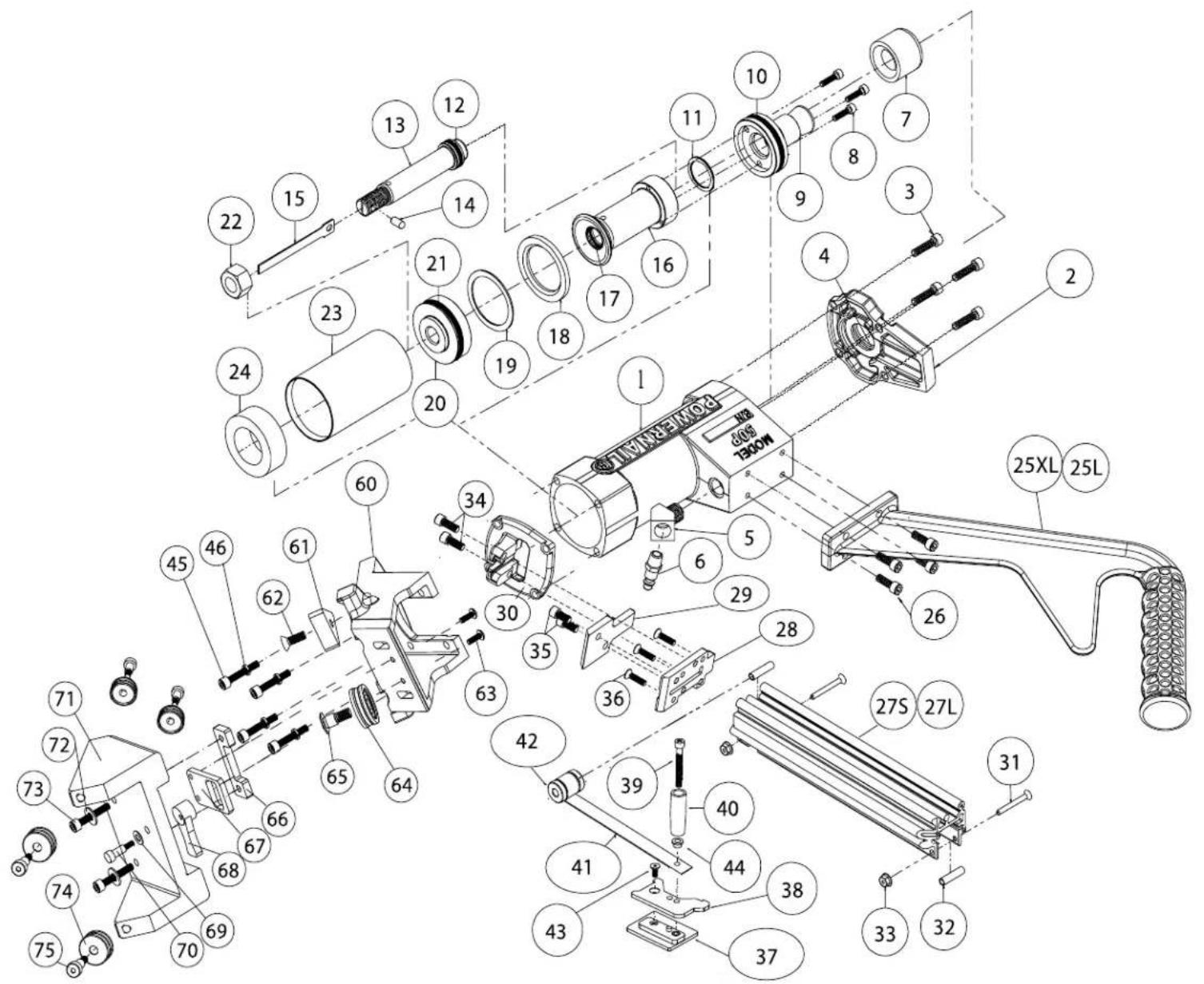
text_image
Exploded view diagram of a mechanical assembly with numbered components and labeled partsFLEX Power Roller Conversion Parts.
60-75
Kits Available - For use on all Model 50P, 50P FLEX, & 50P FLEX Power Rollers
For Step-by-Step Videos and Instructions, Visit our Web Site at: www.Powernail.com
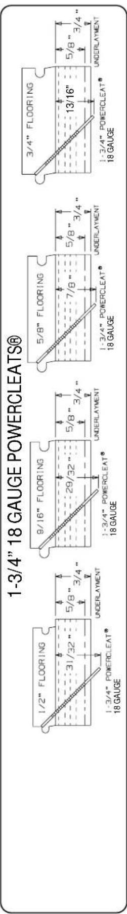
POWERCLEATS LENGTH DETERMINATION CHART
This chart will assist you in determining the proper length of Powercleats to use for various thicknesses of flooring. Approximate vertical penetration of the Powercleat under the hardwood floor is shown for each application. This is only a guide. Results should be tested in the field before proceeding.
Nail Penetration for 3/4" and 5/8" Underlayment
text_image
1-3/4" 18 GAUGE POWERCLEATS® 1/2" FLOORING 31/32" 5/8" 3/4" UNDERLAYMENT 1-3/4" POWERCLEAT® 18 GAUGE 9/16" FLOORING 29/32" 5/8" 3/4" UNDERLAYMENT 1-3/4" POWERCLEAT® 18 GAUGE 5/8" FLOORING 7/8" 5/8" 3/4" UNDERLAYMENT 1-3/4" POWERCLEAT® 18 GAUGE 3/4" FLOORING 13/16" 5/8" 3/4" UNDERLAYMENT 1-3/4" POWERCLEAT® 18 GAUGE
text_image
1-1/2" 18 GAUGE POWERCLEATS® 3/8" FLOORING 27/32" 5/8" 3/4" UNDERLAYMENT 1-1/2" POWERCLEAT® 18 GAUGE 1/2" FLOORING 25/32" 5/8" 3/4" UNDERLAYMENT 9/16" FLOORING 3/4" 5/8" 3/4" UNDERLAYMENT 1-1/2" POWERCLEAT® 18 GAUGE 5/8" FLOORING 11/16" 5/8" 3/4" UNDERLAYMENT 1-1/2" POWERCLEAT® 18 GAUGE 3/4" FLOORING 5/8" 5/8" 3/4" UNDERLAYMENT 1-1/2" POWERCLEAT® 18 GAUGE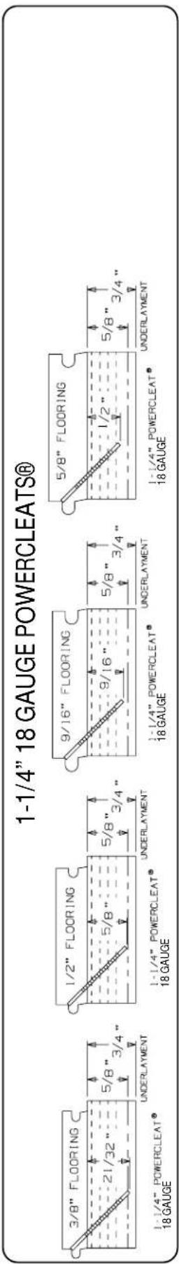
text_image
1-1/4" 18 GAUGE POWERCLEATS® 3/8" FLOORING 21/32" 5/8" 3/4" UNDERLAYMENT 1-1/4" POWERCLEAT® 18 GAUGE 1/2" FLOORING 5/8" 5/8" 3/4" UNDERLAYMENT 9/16" FLOORING 9/16" 5/8" 3/4" UNDERLAYMENT 5/8" 1/2" 5/8" 3/4" 1-1/4" POWERCLEAT® 18 GAUGE 5/8" FLOORING 1-1/4" POWERCLEAT® 18 GAUGE UNDERLAYMENT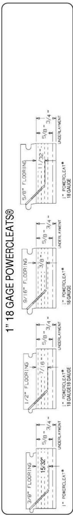
text_image
1" 18 GAGE POWERCLEATS® 3/8" FLOORING 15/32" 5/8" 3/4" 1" POWERCLEAT® UNDERLAYMENT 1/2" FLOORING 7/16" 5/8" 3/4" 1" POWERCLEAT® 18 GAUGE18 GAUGE 9/16" FLOORING 3/8" 5/8" 3/4" 1" POWERCLEAT® 18 GAUGE 5/8" FLOORING 11/32" 5/8" 3/4" 1" POWERCLEAT® 18 GAUGE UNDERLAYMENT©Powernail Company 2012
| PROBLEM | POSSIBLE CAUSE SOLUTION | ||
| 1 | Driving blade does not retract | 1. Zero or Low air pressure | Check air supply for 80 psi minimum to 110 psi maximum |
| 2. Lack of lubrication | Manually lubricate through male air inlet fitting | ||
| 3. Excessive dirt inside nailer Disassemble and clean | |||
| 4. Bent or burred driving blade Replace driving blade (#15) | |||
| 5. Seals worn out Replace all seals (Seal Kit) | |||
| 6. U-Cup Lip Seals installed upside down Replace all seals (Seal Kit) | |||
| 2 | Driving blade retracts slowly | 1. Low air pressure Turn up air pressure to 80-110 psi max | |
| 2. Bent or burred driving blade Replace driving blade (#15) | |||
| 3. Air supply restricted by small orifice | Use 1/4" minimum diameter air fittings | ||
| 4. U-Cup Lip Seals installed upside down Replace all seals (Seal Kit) | |||
| 5. Excessive dirt inside nailer Disassemble, clean and lubricate | |||
| 3 | Nail is not countersunk | 1. Low air pressure Turn up air pressure to 80-110 psi max | |
| 2. Broken Driving Blade Replace Driving Blade (#15) | |||
| 3. Nail hit hard surface Move from obstruction | |||
| 4. Piston U-Cup Lip Seal installed upside down Replace all seals (Seal Kit) | |||
| 5. Driving blade jam nut came loose Retighten or replace jam nut (#22) | |||
| 6. Worn out gate Replace gate. (#28) | |||
| 4 | Nailer leaks air | 1. Air supply fittings loose | Tighten all air line fitting connections |
| 2. Excess air pressure blew out seals | Check air supply for 110 psi maximum—replace all seals | ||
| 3. Plunger screws loose | Tighten 3 plunger screws (#8) | ||
| 4. Cracked or damaged body Replace body (#1) | |||
| 5. Seals worn out Replace all seals (Seal Kit) | |||
| 6. Seals need to be seated | Dry fire Nailer | ||
| 5 | Bottom of nail-er cracked off | 1. Operated without rubber bumper installed | Replace damaged parts |
| 2. Excessive air pressure used | Replace damaged parts | ||
| 6 | Nails jam in nailer | 1. Not using 18 gauge Powercleats nails | Use 18 gauge Powercleats nails only |
| 2. Continued use after a short hit | Clear nail immediately after short hit | ||
| 3. Nail pusher damaged or spring broken | Replace nail pusher assembly (#A-10) | ||
| 4. Nail channel lose | Tighten nail channel retaining screws (#34,#45) | ||
| 5. Bent nail stuck in nail guide | Disassemble and clear out bent nail | ||
| 6. Hit another set nail or hard object | Move from obstruction | ||
| 7. Nail gate worn out Replace nail gate (#28) | |||
| 7 | Plunger locked up—won't move or fi re | 2. Lack of lubrication | Manually lubricate through male air inlet fitting |
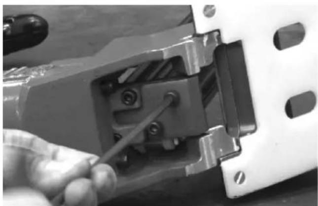
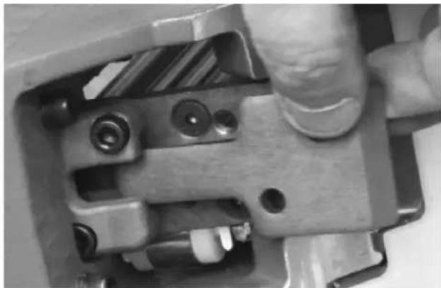
Clearing a jam with the new Revision 2 Foot.
- Using a 3/16" hex wrench, remove the two gate plate screws.
natural_image
Close-up of a hand using a screwdriver to adjust or install a mechanical component (no visible text or symbols)- Inspect and clear any jams in the drive blade pathway.
natural_image
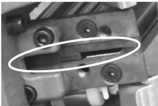
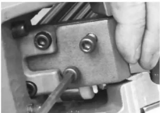
Close-up of a mechanical component with a highlighted oval area (no visible text or symbols)- Slide and remove the gate plate.
natural_image
Close-up of a hand operating a mechanical clamp or bracket component (no visible text or symbols)- Re-install the gate plate and screws. Tighten firmly.
natural_image
Close-up of a hand using a tool to adjust or install a mechanical component (no visible text or symbols)Nailer is now ready for use.
Check out our Repair and Maintenance Videos online at: https://www.powernail.com/service-videos/