AXDIS-PO13 - Uncategorized Metra - Free user manual and instructions
Find the device manual for free AXDIS-PO13 Metra in PDF.

| Product Type | Antenna Adapter |
| Brand | Metra |
| Model | AXDIS-PO13 |
| Compatible Vehicles | Select 2000-2010 Mazda, Ford, and Lincoln models |
| Connector Type | ISO to JIS |
| Function | Allows aftermarket stereo installation while retaining factory antenna and steering wheel controls |
| Dimensions | 4.5 x 2.5 x 0.75 inches |
| Weight | 0.15 lbs |
| Material | ABS Plastic, Copper Wiring |
| Input Power | 12V DC |
| Antenna Input | Motorola Female |
| Antenna Output | ISO Male |
| Included Components | 1x Adapter Harness, 1x Instruction Manual |
| Installation Difficulty | Beginner - Plug and Play |
| Certifications | CE, RoHS |
| Warranty | 1 Year Limited |
| Color | Black |
| Operating Temperature | -40°F to 185°F |
Frequently Asked Questions - AXDIS-PO13 Metra
User questions about AXDIS-PO13 Metra
0 question about this device. Answer the ones you know or ask your own.
Ask a new question about this device
Download the instructions for your Uncategorized in PDF format for free! Find your manual AXDIS-PO13 - Metra and take your electronic device back in hand. On this page are published all the documents necessary for the use of your device. AXDIS-PO13 by Metra.
USER MANUAL AXDIS-PO13 Metra
natural_image
Collection of various electronic devices and connectors, including a black rectangular device with ports and various colored cables (no visible text or labels)Data Interface with SWC
Porsche (with MOST 25 amp) 2010-2016
Visit axxessinterfaces.com for more detailed information about the product and up-to-date vehicle specific applications
INTERFACE FEATURES
- Provides accessory power
• Retains RAP (retained accessory power) - Designed for MOST fiber amplified system
-
Retains reverse camera
-
Micro-B USB updatable
- Provides NAV outputs (parking brake, reverse, speed sense)
- Retains steering wheel controls
- Retains balance
INTERFACE COMPONENTS
- AXDIS-P013 interface • AXDIS-P013 harness • AXDIS-P013 MOST-25 amplifier interface • AXSWC harness • AXSWC interface
• Female 3.5mm connector with stripped leads
APPLICATIONS
Porsche
Panamera 2010-2016 PCM 3.1
Cayenne 2012-2016 PCM 3.1
911 (991) 2012-2016 PCM 3.1
TABLE OF CONTENTS
Connections 2
Installing the AXDIS-P013 interface ....3
Installing the Fiber Optic Cable....3
Programming the AXSWC interface ....4
TOOLS REQUIRED
- Wire cutter
- Crimp tool and connectors (ex. butt splice connectors, bellcaps, etc.)
or
• Solder gun, solder, and heat shrink - Tape
- Zip-ties
ATTENTION! With the key out of the ignition, disconnect the negative battery terminal before installing this product. Ensure that all installation connections are secure before cycling the ignition to test this product. NOTE: Refer to the instructions included with the aftermarket radio.
CONNECTIONS
From the AXDIS-P013 harness to the aftermarket radio, connect as indicated:
- Black wire to the ground wire.
- Yellow wire to the battery wire
- Blue wire to the power antenna wire.
- Blue/White wire to the amp turn on wire.
- Brown wire to the mute wire.
- Orange wire to the illumination.
- Red wire to the accessory wire.
NOTE: There will an accessory wire from the Steering Wheel Control harness to connect as well. The following (3) wires are only for multimedia/navigation radios that require these wires.
- Blue/Pink wire to the VSS/speed sense wire.
- Green/Purple wire to the reverse wire.
• Light Green wire to the parking brake wire.
Tape off and disregard the following (8) wires, they will not be used in this application:
- Gray, Gray/Black, Green, Green/Black, Purple, Purple/Black, White, White/Black
Connect the Red and White RCA jacks to the front amplifier output jacks of the aftermarket radio.
From the AXSWC harness to the aftermarket radio:
This harness is only to be used if the vehicle is equipped with steering wheel controls.
- Connect the Red wire to the accessory wire.
For the radios listed below: Connect the female 3.5mm connector with stripped leads to the male 3.5mm SWC jack from the Steering Wheel Control harness. Tape off and disregard remaining wires.
- Eclipse: Connect the SWC wire, Brown to the Brown/White wire of the connector. Then connect the remaining SWC wire, Brown/White to the Brown wire of the connector.
- Metra OE: Connect the SWC (Key 1) wire Gray to the Brown wire.
- Kenwood or select JVC with a SWC wire: Connect the Blue/Yellow wire to the Brown wire.
NOTE: If the Kenwood radio auto detects as a JVC, manually set the radio type to Kenwood. See the instructions under changing radio type.
• XITE: Connect the SWC (SWC-2) wire from the radio to the Brown wire. - Parrot Asteroid Smart or Tablet: Connect the 3.5mm jack into the AX-SWC-PARROT (sold separately), and then connect the 4-pin connector from the AX-SWC-PARROT into the radio. NOTE: The radio must be updated to rev. 2.1.4 or higher software.
- Universal "2 or 3 wire" radio: Connect the SWC wire, (Key-A or SWC-1) to the Brown wire of the connector. Then connect the remaining SWC wire,(Key-B or SWC-2) to the Brown/White wire of the connector. If the radio comes with a third wire for ground, disregard this wire. NOTE: After the interface has been programmed to the vehicle, refer to the manual provided with the radio for assigning the SWC buttons. Contact the radio manufacturer for more information.
For all other radios: Connect the 3.5mm jack into the port on the radio designated for an external SWC interface. Refer to the manual provided with the radio if in doubt as to where the 3.5mm jack connects.
Adding aftermarket camera: Connect the Yellow female RCA cable from the aftermarket camera to the male RCA video wire. Then plug the Yellow male RCA video wire into the reverse camera input of the aftermarket radio.
INSTALLATION
Installing the AXDIS-P013 Interface:
With the key in the off position:
- Connect the AXDIS-P013 harness to the AXDIS-P013 interface.
- Connect the AXDIS-P013 harness to the AXDIS-P013 MOST amplifier interface.
- Connect the AXDIS-P013 harness to the wiring harness in the vehicle.
- Connect the USB retention harness from the vehicle to the aftermarket radio.
- Connect the AXSWC harness to the AXSWC interface, and then to the AXDIS-P013 interface.
Installing the Fiber Optic Cable:
Removal of the original fiber optic connection is required to adapt to the Media Oriented System Transport (MOST) interface. The black connector housing uses a different keyway than the MOST interface.
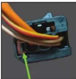
- From the original Fiber Optic Connector: Using a pick tool, carefully pull this tab towards the outside edge for the connector housing. Gently remove the fiber optic insert from the connector. (Figure A)
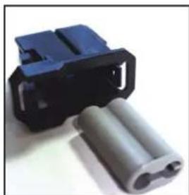
- From the MOST Interface: Using the same steps from above, remove the gray insert from the black fiber optic housing. Replace the gray connector with the fiber optic cables into the MOST interface's black connector housing. (Figure B)
- Plug the MOST connector into the fiber decoder box.
natural_image
Close-up of a cable being inserted into a plastic component, with a green arrow pointing to the cable (no text or symbols visible)(Figure A) (Figure B)
natural_image
Close-up of a blue plastic connector with two cylindrical components (no text or symbols visible)PROGRAMMING
Programming the AXSWC Interface
- Connect the AXSWC to the AXDIS-P013 harness.
- Press and hold the Volume Up button on the steering wheel.
- Turn the ignition on. The L.E.D. in the AXSWC interface will start flashing rapidly, as the AXSWC interface searches for the auto manufacturer.
- After a few seconds the L.E.D. should stop flashing rapidly, then go out for approximately (2) seconds.
- After that (2) seconds there will be a series of (7) Green flashes, some short, and some long. The long flashes represent the wires that are connected from the vehicle to the AXSWC interface. The 3rd, 4th, 5th, and 6th flashes should be longer.
- The L.E.D. will pause for another (2) seconds, then begin flashing Red (up to 23 times) as the AXSWC interface locates the aftermarket radio installed. Refer to the L.E.D Feedback Legend for the number of times the light should flash for the radio installed.
- This is the end of the auto detection stage. If the AXSWC interface detected the vehicle and radio successfully, the L.E.D. will light up solid Red. If not, refer to the troubleshooting documents available at axxessinterfaces.com.
- Release the Volume Up button. Test all functions of the installation for proper operation before reassembling the dash. Refer to the Steering Wheel Control documents available at axxessinterfaces.com for customizing the buttons, if so desired.
PROGRAMMING
L.E.D. Feedback: The (23) Red L.E.D. flashes represent a different radio manufacturer for the AXSWC interface to detect. For example, if you are installing a JVC radio, the AXSWC interface will flash Red (5) times, then stop. Following is the L.E.D Feedback Legend, which indicates the flash count of the radio manufacturer
| L.E.D FEEDBACK LEGEND | |
| Flash Count | Radio |
| 1 | Eclipse (type 1)† |
| 2 | Kenwood ‡ |
| 3 | Clarion (type 1) † |
| 4 | Sony / Dual |
| 5 | JVC |
| 6 | Pioneer / Jensen |
| 7 | Alpine * |
| 8 | Visteon |
| 9 | Valor |
| 10 | Clarion (type 2) † |
| 11 | Metra OE |
| 12 | Eclipse (type 2) † |
| 13 | LG |
| 14 | Parrot ** |
| 15 | XITE |
| 16 | Philips |
| 17 | TBA |
| 18 | JBL |
| 19 | Insane |
| 20 | Magnadyne |
| 21 | Boss |
| 22 | Axxera |
| 23 | Axxerra (type 2) |
KEYNOTES
* If the AXSWC interface flashes Red (7) times, and an Alpine radio is not installed, that means there is an open connection not accounted for. Verify that the 3.5mm jack is connected to the correct steering wheel jack/wire in the radio.
** The AXSWCH-PAR is required (sold separately). Also, the software in the radio must be rev. 2.1.4 or higher.
^ If a Clarion or Eclipse radio is installed and the steering wheel controls do not function, change the radio to Clarion (type 2) or Eclipse (type 2) respectively. If the steering wheel controls still do function, refer to the Changing Radio Type document available at axxessinterfaces.com.
If a Kenwood radio is installed and the L.E.D. feedback flashes (5) times instead of (2), manually change the radio type to Kenwood. To do this, refer to the Changing Radio Type document available at axxessinterfaces.com.

AXDIS-PO13 INSTALLATION INSTRUCTIONS

Having difficulties? We're here to help.
Contact our Tech Support line at: 386-257-1187
Or via email at: techsupport@metra-autosound.com
Tech Support Hours (Eastern Standard Time)
Monday - Friday: 9:00 AM - 7:00 PM
Saturday: 10:00 AM - 7:00 PM
Sunday: 10:00 AM - 4:00 PM

KNOWLEDGE IS POWER
Enhance your installation and fabrication skills by enrolling in the most recognized and respected mobile electronics school in our industry. Log onto www.instellerinstitute.edu or call 386-672-5771 for more information and take steps toward a better tomorrow.

Metra recommends MECP certified technicians