CMS491P2 - Uncategorized Chief - Free user manual and instructions
Find the device manual for free CMS491P2 Chief in PDF.

User questions about CMS491P2 Chief
0 question about this device. Answer the ones you know or ask your own.
Ask a new question about this device
Download the instructions for your Uncategorized in PDF format for free! Find your manual CMS491P2 - Chief and take your electronic device back in hand. On this page are published all the documents necessary for the use of your device. CMS491P2 by Chief.
USER MANUAL CMS491P2 Chief
INSTALLATION INSTRUCTIONS ADDENDUM
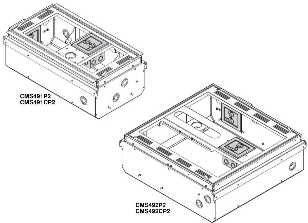
Powered Ceiling Storage Boxes
DISCLAIMER
Milestone AV Technologies, and its affiliated corporations and subsidiaries (collectively, "Milestone"), intend to make this manual accurate and complete. However, Milestone makes no claim that the information contained herein covers all details, conditions or variations, nor does it provide for every possible contingency in connection with the installation or use of this product. The information contained in this document is subject to change without notice or obligation of any kind. Milestone makes no representation of warranty, expressed or implied, regarding the information contained herein. Milestone assumes no responsibility for accuracy, completeness or sufficiency of the information contained in this document.
Chief® is a registered trademark of Milestone AV Technologies. All rights reserved.

IMPORTANT SAFETY INSTRUCTIONS

WARNING
alerts you to the possibility of
serious injury or death if you do not follow the instructions.

CAUTION
alerts you to the possibility of
damage or destruction of equipment if you do not follow the corresponding instructions.

WARNING:
FAILURE TO READ AND
FOLLOW THE FOLLOWING INSTRUCTIONS CAN RESULT IN SERIOUS PERSONAL INJURY, DAMAGE TO EQUIPMENT OR VOIDING OF FACTORY WARRANTY. It is the installer's responsibility to make sure all components are properly assembled and installed using the instructions provided.
READ ALL INSTRUCTIONS BEFORE USING THIS PRODUCT!!!!

DANGER:
TO REDUCE THE RISK OF
ELECTRIC SHOCK:
- Always turn off power at source before installing the outlet.

WARNING: TO REDUCE THE RISK OF
BURNS, FIRE, ELECTRIC SHOCK, OR INJURY TO PERSONS:
• Always turn off power at source before servicing or removing the outlet.
- Do not use outdoors - for indoor use only!
- Route cables as shown in these installation instructions.
- To disconnect, turn off power at source.

WARNING: RISK OF ELECTRIC SHOCK!
Make sure the outlet is properly grounded. See Grounding Instructions.

WARNING: Failure to provide adequate
structural strength for this outlet can result in serious personal injury or damage to equipment! It is the installer's responsibility to make sure the structure to which this outlet is attached can support the weight of the box.

CAUTION: This equipment must be installed
and assembled by qualified service personnel in accordance with local building and electrical codes.
NOTE: Knockouts are provided for ease of installation. Any unused knockouts that have been punched are to be closed up with a metal plug.
NOTE: Ambient Temperature - The manufacturer's maximum ambient temperature is 104°F (40°C) and minimum ambient temperature is 30°F (-1°C) so that the installer is able to determine acceptability of use of Accessories and components.
--SAVE THESE INSTRUCTIONS--
DIMENSIONS
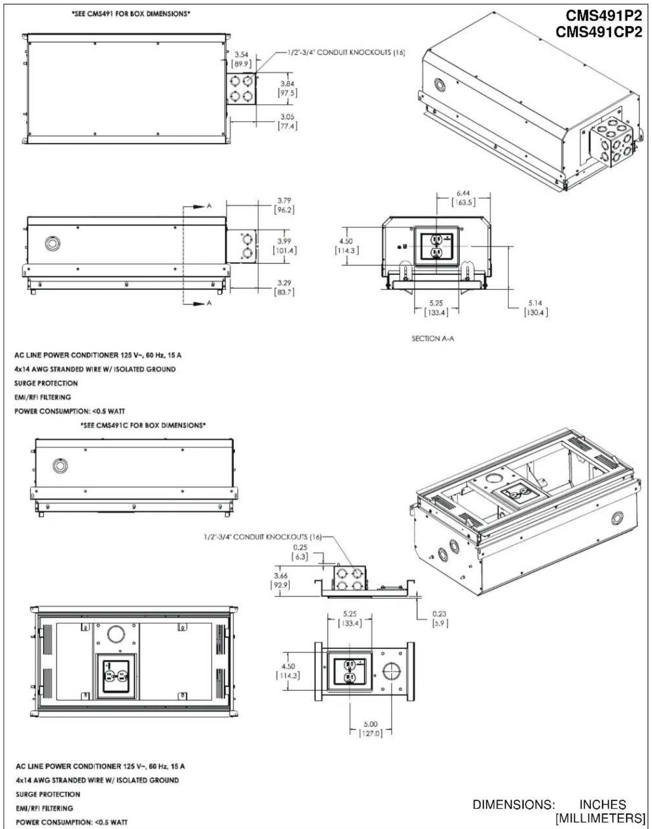
AC LINE POWER CONDITIONER 125 V\~, 60 Hz, 15 A
4x14 AWG STRANDED WIRE W/ ISOLATED GROUND
SURGE PROTECTION
EMI/RFI FILTERING
POWER CONSUMPTION: <0.5 WATT
AC LINE POWER CONDITIONER 125 V\~, 60 Hz, 15 A
4x14 AWG STRANDED WIRE W/ ISOLATED GROUND
SURGE PROTECTION
EMI/RFI FILTERING
POWER CONSUMPTION: <0.5 WATT
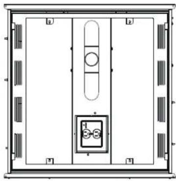
DIMENSIONS: INCHES [MILLIMETERS]
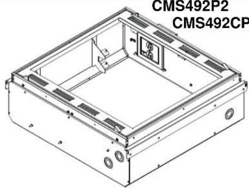
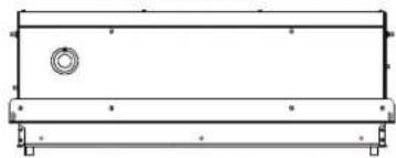
DIMENSIONS - continued
*SEE CMS492 FOR BOX DIMENSIONS*
![3.54 [89.9] 1/2"-3/4" CONDUIT KNOCKOUTS (16) 3.84 [97.5] 3.05 [77.4]](/content/2026/06/1166931/images/2443db18d040ff28a053350efc695771f44437cc11b6c4ca49150dd818f74d79.jpg)
CMS492P2
CMS492CP2
natural_image
Technical line drawing of a rectangular electronic device housing with mounting holes and internal compartments (no text or symbols)![3.79 [96.2] 3.99 [101.4] 3.29 [83.7]](/content/2026/06/1166931/images/c99c9efb96c69bdf949d294479601d1e698a71945f8eefb9b3c7cde170e64936.jpg)
![4.50 [114.3] 5.25 [133.4] 5.52 [140.3] SECTION A-A 5.78 [146.9]](/content/2026/06/1166931/images/ab45cf5533113b72c5f3b6339156eb05043708a6bd560abebb8ed7406cb02692.jpg)
AC LINE POWER CONDITIONER 125 V\~, 60 Hz, 15 A
4x14 AWG STRANDED WIRE W/ ISOLATED GROUND
SURGE PROTECTION
EMI/RFI FILTERING
POWER CONSUMPTION: <0.5 WATT
*SEE CMS492C FOR BOX DIMENSIONS*
natural_image
Pure technical line drawing of a rectangular mechanical component with mounting holes and a central circular feature (no text or symbols)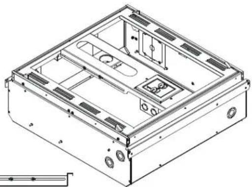
natural_image
Technical line drawing of a mechanical housing or enclosure with internal compartments and mounting holes (no text or symbols)1/2"-3/4" CONDUIT KNOCKOUTS (16)
![0.25 [6.3] 3.66 [92.9] 0.17 [4.3]](/content/2026/06/1166931/images/62f72fbd24621d11f372818e3cb9b1bc6fbfb88c5d17541fb19408cf74660431.jpg)
natural_image
Top-down architectural or mechanical layout diagram with no visible text, numbers, or symbols![5.25 [133.4] 4.50 [114.3] 4.97 [126.1] MIN 5.91 [150.1] MAX 15.31 [389.0]](/content/2026/06/1166931/images/c988738a5e85dc093aa930c6ebd02f5477396b26965d0bf22cd2edca1c1178d6.jpg)
AC LINE POWER CONDITIONER 125 V\~, 60 Hz, 15 A
4x14 AWG STRANDED WIRE W/ ISOLATED GROUND
SURGE PROTECTION
EMI/RFI FILTERING
POWER CONSUMPTION: <0.5 WATT
DIMENSIONS: INCHES [MILLIMETERS]
LEGEND
 | Tighten Fastener |  | Phillips Screwdriver |
| Apretar elemento de fijación | Destornillador Phillips | ||
| Befestigungsteil festziehen | Kreuzschlitzschraubendreher | ||
| Apertar fixador | Chave de fendas Phillips | ||
| Serrare il fissaggio | Cacciavite a stella | ||
| Bevestiging vastdraaien | Kruiskopschroevendraaier | ||
| Serrez les fixations | Tournevis à pointe cruciforme | ||
 | Loosen Fastener |  | Adjust |
| Aflojar elemento de fijación | Ajustar | ||
| Befestigungsteil lösen | Einstellen | ||
| Desapertar fixador | Ajustar | ||
| Allentare il fissaggio | Regolare | ||
| Bevestiging losdraaien | Afstellen | ||
| Desserrez les fixations | Ajuster |
TOOLS REQUIRED FOR INSTALLATION
PARTS

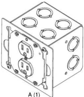
natural_image
Isometric line drawing of a cube with multiple circular cutouts and mounting holes (no text or symbols)[EGX-SF2 Power Conditioner Outlet]
| Grounding screw installed at factory. (See Figure 4)
10-32 grounding screw


Earthing symbol IEC 60418 No. 5019 affixed adjacent to grounding terminal
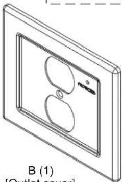
natural_image
Isometric line drawing of a wall-mounted device with two circular cutouts and a label B (1) at the bottom (no text or symbols on the diagram itself)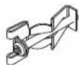
C (2) [Clip - not used]
Isolated Ground Receptacle
This product incorporates an isolated ground receptacle, identified by the orange triangle on its face. This feature may be useful to reduce common noise in the connected equipment. Its intended use is to reduce electrical noise (electromagnetic interference) by purposely insulating the grounding circuit from any metallic wiring system. The ground pin of the receptacle is connected to the green/yellow wire and is isolated from the metal mounting yoke of the receptacle. The accessible metal of the product is connected to the green wire. If it is not desired to use this feature, connect the green/yellow and green wires together.
References
Application Guide for Isolated Ground Wiring Devices 2007, National Electrical Manufacturers Association (NEMA)
IEEE Std 1100™-2005, "IEEE Recommended Practice for Powering and Grounding Electronic Equipment" (Emerald Book), Section 8.5.3.2.
IEEE Std 142™-2007, "IEEE Recommended Practice for Grounding of Industrial and Commercial Power Systems" (Green Book), Sections 5.5.1, 5.5.2
NFPA-70, "National Electrical Code", Article 250.146 Connecting Receptacle Grounding Terminal to Box.
• (D) Isolated Ground Receptacles. Where installed for the reduction of electrical noise (electromagnetic interference) on the grounding circuit, a receptacle in which the grounding terminal is purposefully insulated from the receptacle mounting means shall be permitted. The receptacle grounding terminal shall be connected to an insulated equipment grounding conductor run with the circuit conductors. This equipment grounding conductor shall be permitted to pass through one or more panel boards without a connection to the panel board grounding terminal bar as permitted in 408.40, Exception, so as to terminate within the same building or structure directly at an equipment grounding conductor terminal of the applicable derived system or service. Where installed in accordance with the provisions of this section, this equipment grounding conductor shall also be permitted to pass through boxes, wire ways, or other enclosures without being connected to such enclosures.
- Informational Note: Use of an isolated equipment grounding conductor does not relieve the requirement for grounding the raceway system and outlet box.
C22.2 No. 1, "Canadian Electrical Code, Part 1", Rule 10-906 Bonding conductor connection to circuits and equipment.
• (6) A bonding jumper shall be installed to connect the bonding conductor to the grounding terminal of a receptacle and in such a manner that disconnection or removal of the receptacle will not interfere with, or interrupt grounding continuity.
• (7) In the case of metallically enclosed systems where the grounding path is provided by the metal enclosure, a bonding jumper shall be installed to bond the grounding terminal of the receptacle to the enclosure.
• (8) Notwithstanding Sub-rules (6) and (7), the bonding jumper, in the case of receptacles having grounding terminals isolated from the mounting strap required for special equipment, shall be
permitted to be extended directly back to the distribution panel.

WARNING: IMPROPER INSTALLATION CAN RESULT IN DEATH OR SERIOUS PERSONAL INJURY! This mounting system should be installed by qualified personnel.
IMPORTANT ! : In addition to the CMS491/CMS491C/CMS492/CMS492C installation instructions accompanying the products, the following steps must also be taken when installing the CMS491P2, CMS491CP2, CMS492P2, and CMS492CP2.
The CMS491P2, CMS491CP2, CMS492P2, and CMS492CP2 must be connected to a 15 Amp branch circuit.
Installing EGX-SF2
- Loosen two Phillips head screws holding EGX-SF2 (A) outlet box to outer housing. (See Figure 1)
- Rotate outlet box counter-clockwise until it is free to be removed from housing. (See Figure 1)
- Remove outlet box from housing. (See Figure 1)
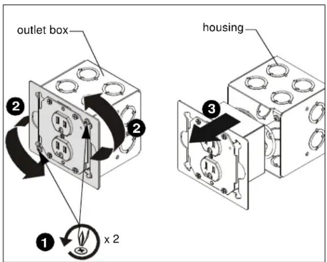
Figure 1
- Wire the EGX-SF2 outlet box as required making sure the wiring passes through the outlet hole in the housing. Refer to Table 1 and Table 2 for input and output specifications. (See Figure 2)
Table 1: Input Specifications
| Input | |
| Input voltage, frequency | 125 V AC, 60 Hz |
| Input connection type | 4x14 AWG stranded, UL Style1015, CSA TEW |
| Input Wire colors | Black - LineWhite - NeutralGreen - Box GroundGreen/Yellow - Isolated Ground |
| Input wire length (ft.) | 1 (with a 3/4" stripped end) |
Table 2: Output Specifications
| Output | |
| Output | 15 A, 1875 W |
| Power consumption | <0.5 watt |
| Fuses | Thermal current interrupting circuits are in MOVs |
| Quantity/Type | Duplex NEMA 5-15R Isolated Ground Receptacle |
| Color/Markings | Grey with protection symbol (Orange triangle) |

CAUTION: Isolated ground-mounting means NOT grounded. Grounding wire connection required.
IMPORTANT ! : If a separate isolated green/yellow ground wire is installed in the building wiring, attach it separately to the green/yellow isolated ground wire on box. If there is no separate green/yellow isolated ground wire, connect green ground wire to both green/yellow isolated ground wire and green box ground wire on box.
NOTE: The grounding conductors serving this outlet are to be connected to earth ground at the service equipment or other acceptable building earth ground such as the building frame in the case of a high-rise steel-frame structure. Connections should be made with minimum AWG 14 copper wire intended for use on a 15 Amp circuit. The conductors used to connect the outlet to the line and to ground shall not be any longer than necessary and shall avoid unnecessary bends.
NOTE: An insulated grounding conductor that is identical in size and insulation material and thickness to the grounded and ungrounded circuit supply conductors, except that it is green with or without one or more yellow stripes, is to be installed as part of the circuit that supplies the outlet. Refer to Table 250-122 of the National Electrical Code regarding the appropriate size of the grounding conductor.
NOTE: Pressure terminal or pressure splicing connectors and soldering lugs used in the installation of the outlet shall be identified as being suitable for the material of the conductors. Conductors of dissimilar metals shall not be intermixed in a terminal or splicing connector where physical contact occurs between dissimilar conductors unless the device is identified for the purpose and conditions of use.
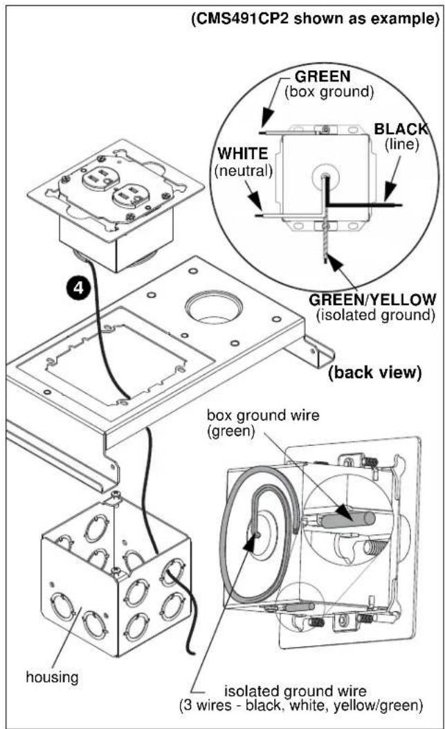
Figure 2
- Position the EGX-SF2 housing into side opening of CMS491/CMS492; (See Figure 4) OR, into top of projector mount plate in the CMS491C/CMS492C underneath the opening where the outlet box will be reattached. (See Figure 3) OR (See Figure 4)
- Reinstall outlet box in the EGX-SF2 housing. (See Figure 3) OR (See Figure 4)
- Rotate outlet box clockwise until it is in proper position to be secured to the EGX-SF2 housing. (See Figure 3) OR (See Figure 4)
- Tighten two Phillips screws to secure outlet box to EGX-SF2 housing. (See Figure 3) OR (See Figure 4)
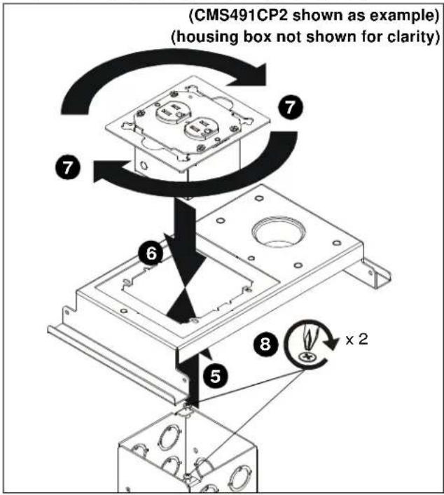
Figure 3
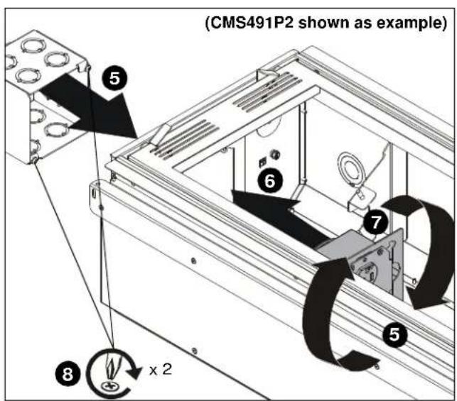
Figure 4
- Make sure grounding screw is properly installed. (See Figure 5)

WARNING: ELECTRICAL SHOCK HAZARD! Turn off power to device before performing service or connecting to outlet.
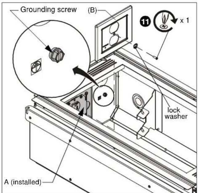
Figure 5
- Remove 6-32 x 1/2" Phillips flat head screw and lock washer from front of EGX-SF2 box. (See Figure 6)
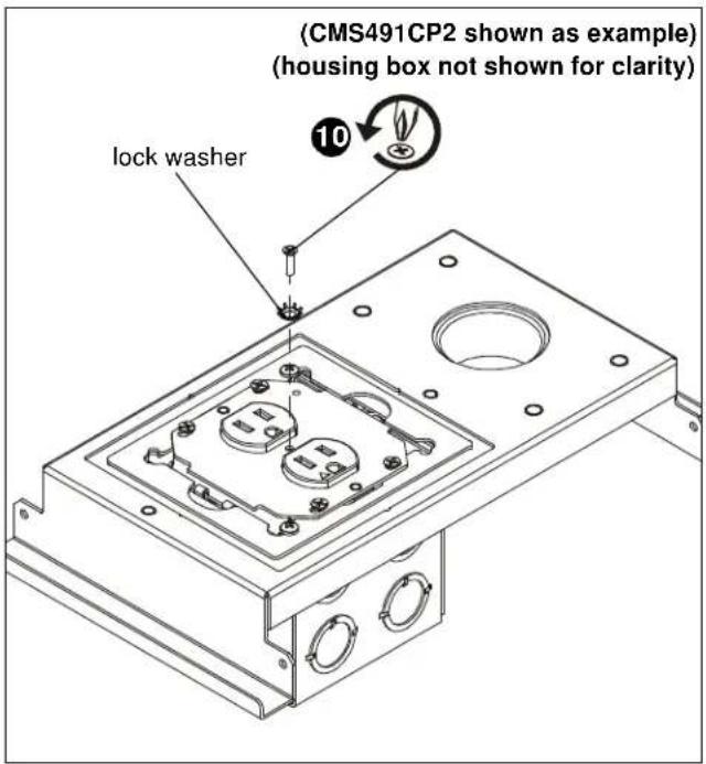
Figure 6
- Install faceplate (B) onto EGX-SF2 using one 6-32 x 1/2" Phillips flat head screw and lock washer previously removed from front of box. (See Figure 5) or (See Figure 7)
NOTE: Make sure LED light on outlet box lines up with hole location on faceplate (B). (See Figure 7)
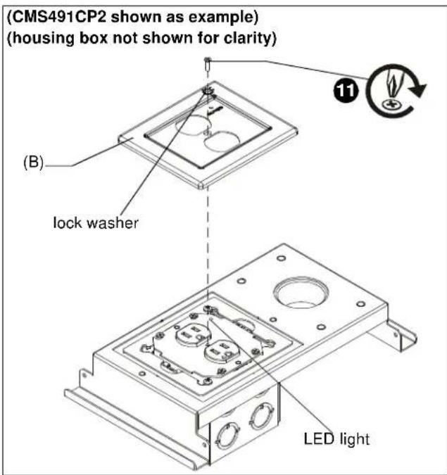
Figure 7
Outlet Box Use
NOTE: The "PROTECTED" light indicates that the surge protection circuitry is active and operational.
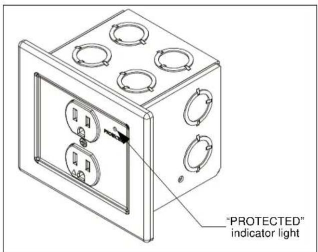
Figure 8
CMS491P2 / CMS492P2 / CMS491CP2 / CMS492CP2
Installation Instructions