7380A - Screen GENELEC - Free user manual and instructions
Find the device manual for free 7380A GENELEC in PDF.

User questions about 7380A GENELEC
0 question about this device. Answer the ones you know or ask your own.
Ask a new question about this device
Download the instructions for your Screen in PDF format for free! Find your manual 7380A - GENELEC and take your electronic device back in hand. On this page are published all the documents necessary for the use of your device. 7380A by GENELEC.
USER MANUAL 7380A GENELEC
natural_image
Exterior view of a black industrial fan or electrical enclosure with ventilation grilles and a circuit board (no visible text or symbols)Genelec 7380A Smart Active Subwoofer
Introduction
Thank you for choosing a Genelec product! Fulfilling our customers' dreams by offering people the most truthful sound reproduction possible has been the source of our enthusiasm since 1978. There's already over one million Genelec monitors around the world - welcome to our story!
All Genelec monitors are designed, hand assembled and individually tested at our factory in lisalmi, Finland. Our products are designed to last for decades and we take care that our customers receive excellent support and technical services throughout the lifetime of the products.
Please register your monitor at http://www.community.genelec.com/. You will receive an extended 5 year warranty for spare parts. More information about our service and technical support: http://www.genelec.com/customer-service.
System Description
The Genelec 7380A SAM subwoofer integrates easily into environments based on analog or digital interfacing. The 7380A even introduces outstanding GLM ^™ features to the lower octaves of monitoring systems based on main speakers from a different vendor.
The 7380A is designed for precise monitoring of multichannel analog audio signals and stereo AES/EBU signals. Multichannel AES/EBU signals can be monitored by using the 9301A multichannel digital audio interface device connected to the subwoofer.
The subwoofer can be fully set up using the controls built into the unit. The 7380A can also be precisely calibrated to the monitoring room acoustics using the Genelec Loudspeaker Manager (GLM) computer software. The GLM software runs on Mac OS and Windows computers and enables detailed acoustic calibration permanently inside the subwoofer. It is also possible to use the GLM software as a monitoring management system for more than 30 SAM monitors and subwoofers.
In its power save mode, the 7380A consumes less than 2 W of power. Energy saving Intelligent Signal Sensing (ISS) can automatically put the subwoofer into a power save mode when audio has been absent for a selected time. Upon sensing an input signal, the subwoofer wakes up to full operation. The time before entering the ISS power save mode can be configured using the GLM software. When the ISS is active you can have your monitoring system ready for action at all times.
Package content
Each subwoofer is supplied with a mains cable, one 5 m GLM network cable and an operating manual.
Genelec Loudspeaker Manager™ (GLM™) Software And GLM User Kit
The GLM software gets the most out of 7380A and tailor-fits it to your room. GLM is available for download free of charge at www.genelec.com/glm. Check in from time to time to take advantage of new features, or consider using the cloud-based version.
A GLM User Kit comprising the necessary hardware, including the GLM Adapter and measuring microphone is needed for building and operating the GLM network. This kit can be purchased at certified Genelec dealers.
Connections
Before connecting signal cables, switch the subwoofer and monitors off.
Analog inputs 1 to 7
The 7380A SAM subwoofer accepts balanced XLR inputs. These are the outputs typically provided in a console or a monitor controller. The maximum balanced audio signal level is +24 dBu.
LFE In
A dedicated XLR input is provided for the analog LFE signal. The bandwidth for a signal fed to the LFE input is 120 Hz. The LFE input sensitivity can be set the same as for the main channels or at +10 dB relative to the main channels. This feature is set using the +10 dB DIP Switch or in the GLM software.
AES/EBU input
One AES/EBU digital audio XLR input is available on the 7380A subwoofer. This can take a stereo digital audio signal.
Multichannel digital audio monitoring is possible with the 9301A interface device. The 9301A connects to the digital audio input in the 7380A subwoofer and expands the number of digital audio inputs to four XLR digital audio inputs. This supports a 7.1 audio system, including an LFE channel.
Analog Output 1 to 7
Analog balanced XLR connectors connect the subwoofer to monitors.
The 7380A SAM subwoofer supports two bass management methods. Depending on the chosen bass management method, these analog outputs carry either unfiltered copy of the inputs (SAM distributed crossover) or a high-pass filtered signal (fixed crossover).
The fixed crossover is set to 85 Hz. The SAM distributed crossover method allows the subwoofer crossover to be adjusted in the GLM software from 50 Hz to 100 Hz.
See chapter "Bass Management" for details.
LFE Out
The analog LFE Out is a copy of the signal at the analog LFE In. Typically, the LFE Out is used in connecting to the LFE In of the next subwoofer when multiple subwoofers are used together.
Link Out
The sum of the analog inputs 1 to 7 is available at the analog Link Out. The Link Out is used in connecting to the next subwoofer when subwoofers are used together while using analog signals. See chapter "Using Multiple Subwoofers."
Link In
The analog Link In accepts the signal from the analog Link Out. The Link In input is used when multiple subwoofers are used together while using analog signals. When the Link In is connected, the analog inputs 1 to 7 should not be connected.
See chapter "Using Multiple Subwoofers."
OUT1 / Test 1
The analog OUT1 / Test 1 output XLR passes a test tone for aligning the phase of the subwoofer with a monitor.
This test tone has a frequency of 85 Hz when the 7380A SAM subwoofer is set up using the controls built into the subwoofer. The test tone is enabled with the DIP Switch labeled Test Tone. For more details on the use of this output, see the section 'Manual Phase Alignment Method'.
OUT2 / Test 2
This analog output XLR is reserved for future use.
text_image
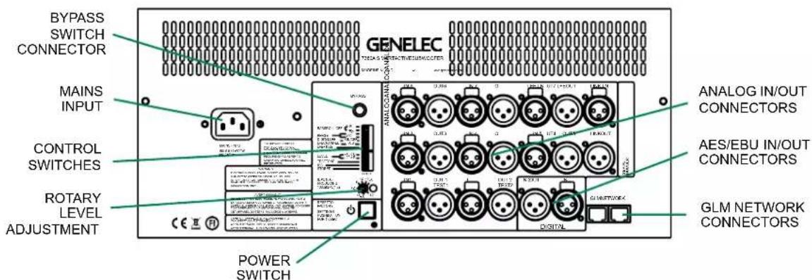
BYPASS SWITCH CONNECTOR MAINS INPUT CONTROL SWITCHES ROTARY LEVEL ADJUSTMENT POWER SWITCH GENELEC ANALOG IN/OUT CONNECTORS AES/EBU IN/OUT CONNECTORS GLM NETWORK CONNECTORSFigure 1. Connector panel of the 7380A.
AES/EBU Out
The AES/EBU Out is a bit-to-bit copy of the digital audio signal on the AES/EBU IN. This output can be used for digital sharing of the audio between subwoofers in the case where multiple subwoofers are used. This output can also be used for distributing a stereo digital audio signal to monitors. This can create a 2.1 digital audio stereo monitoring system.
Bypass
The Bypass input accepts a 6.3 mm tip-ring-sleeve (TRS) or tip-sleeve (TS) plug. This plug supports a contact open/close switch device. Connecting the TIP to the SLEEVE activates the bass management bypass. When the bass management bypass is active, the subwoofer only reproduces the LFE signal and the outputs bypassed to the monitors are exact copies of the inputs.
The Bypass switch is intended to be used when the subwoofer is set up using the controls built in the subwoofer.
The GLM software control enables also bypassing the bass management and offers a wider set of controls and adjustments. When the GLM is used, the TRS bypass control is not needed.
GLM Management Network
All controls and calibration features included in the 7380A SAM subwoofer can be set using the Genelec Loudspeaker Manager (GLM) software. Two GLM Network connectors are provided on the subwoofer for computer control. These connectors accept CAT5 or higher cable (RJ45 connector). Standard CAT cables can be used.
The GLM management network runs a proprietary protocol. This is not an Ethernet connection, do not connect to an Ethernet network.
flowchart
graph TD
    A["Computer"] -->|USB CABLE| B["GLMADAPTER"]
    B -->|USB CABLE| C["Subwoofer"]
    B -->|USB CABLE| D["MONITORS"]
    B -->|USB CABLE| E["GLMNETWORK CABLE"]
    B -->|USB CABLE| F["MICROPHONE PLACEDIN THELISTENING POSITION"]
    B -->|USB CABLE| G["USBCABLE"]
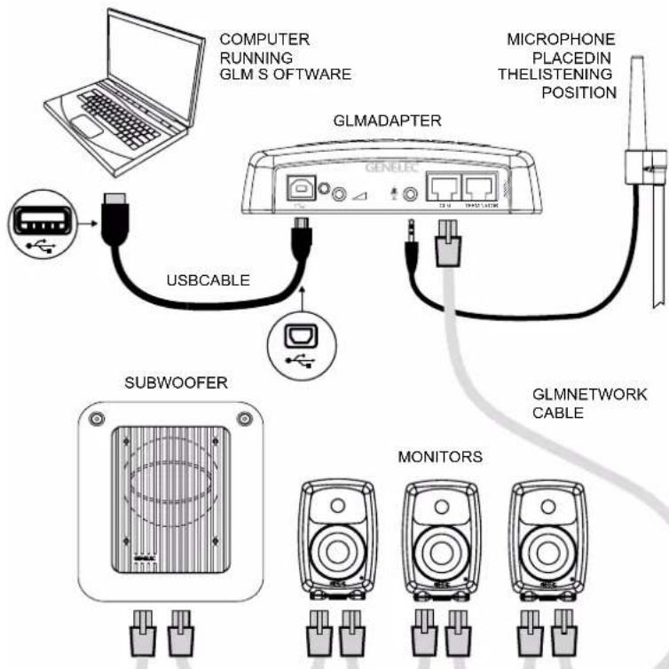
Figure 2. GLM Network cabling. Audio cabling not shown.
Mains Power Input
The main power connection supports a wide mains voltage range (100-240 VAC, 50-60 Hz). This enables the 7380A SAM subwoofer to be plugged in anywhere globally. When the mains power is provided with a generator, inverter, or certain lower-quality UPS devices, we recommend filtering power to remove harmonics and ensuring the voltage supply is stable.
Bass Management
Bass management divides the input audio signal into low frequency and high frequency content at the subwoofer crossover frequency. The signal content below the crossover frequency is reproduced by the subwoofer. The signal content above the crossover frequency is reproduced by the monitors.
The 7380A supports two bass management methods: the centralized bass management method and the distributed bass management method.
Centralized bass management
The centralized bass management method uses fixed 85 Hz crossover filters in the analog output channels in the 7380A SAM subwoofer for the signal feeds going to monitors. All analog signal cables are first routed to the subwoofer's IN connectors and then from the OUT connectors to the respective main monitors. The outgoing signal has the low frequencies removed.
The fixed highpass filters inside the subwoofer can be used when using the in-built controls or with GLM software-based control. However, we recommend the much more flexible distributed bass management method.
Distributed bass management
In the distributed bass management method the monitors and the subwoofer receive full bandwidth audio signal and the filtering is done separately inside each monitor and subwoofer. The lowpass and highpass filters are set in synchrony by the GLM management network. This method is only available in systems where GLM computer management is used and with monitors supporting this method. The subwoofer crossover frequency can be adjusted from 50 Hz to 100 Hz.
The distributed bass management supports three different signal cabling configurations:
- All channels are routed through the subwoofer's IN/OUT connectors to the respective monitors.
- Y-cables split each signal to the subwoofer's IN connector and the monitor's input.
- Signal sources with dual outputs for each channel, one going to the subwoofer, the other going to the monitor.
Use With GLM Control Network
The 7380A SAM subwoofer is fully compatible with Genelec Loudspeaker Manager GLM software, the proprietary Genelec monitor management network, and all Genelec SAM monitors.
Managing the 7380A SAM subwoofer using GLM software control unleashes the full power of room compensation in the 7380A SAM subwoofer, enabling 20 parametric room compensation filters. This powerful room compensation functionality is only available when the GLM is used. Detailed information on the use with the GLM network is presented in the GLM System Operating Manual.
System setup
The 7380A SAM subwoofer reaches its full potential when set up and calibrated using the GLM software. Genelec Loudspeaker Manager GLM and the proprietary Genelec monitor management network offer
- automated acoustic equalization individually for every monitor and subwoofer
- automated level alignment
• distance (acoustic time-of-flight) calibration - aligning of the subwoofers for bass management
for any reproduction system from stereo to complex 3D immersive setups, including one or more subwoofers. GLM setup is fast and accurate. It can precisely address the typical narrow-band low frequency modal resonances and radiation loads of a room and offers precise frequency response compensations. The settings can be controlled with a computer or the settings can be permanently stored in the monitors and subwoofers, to make the setup available at all times even when the computer is not in use. Genelec recommends setting up SAM monitoring systems using the GLM. You can find a detailed description of the setup process and the use of GLM in the GLM System Operating Manual.
The setup using GLM is fast and consists of the following steps:
- Connect a CAT5 (RJ45) cable between each monitor (and subwoofer) and finally to the control network input of the GLM Adapter device (see Figure 1).
- Connect the GLM Adapter device to computer USB connector.
- Using a microphone stand, place the Genelec measurement microphone at the listening location with the microphone pointing upwards and the microphone top at the height of the engineer's ear. The microphone is a part of the GLM User Kit.
- Connect the GLM Adapter device to the computer USB port using cable included in the GLM User Kit.
- Download the GLM software at the Genelec web site (www.genelec.com).
• Install the GLM software and follow the instructions in the software to measure and set up your system. - If you plan to not use a computer for controlling the subwoofer, use the GLM
software to write the setting into the subwoofer (use menu item "Store | Store the Current Group Settings...").
After storing the acoustic settings using the GLM software, when the GLM network is disconnected, the settings are retrieved and activated by setting the STORED switch to the ON position.
With GLM software active and controlling the 7380A SAM subwoofer, the use of analog and digital inputs is controlled by the GLM software entirely. In the software 'Input Type' in the 'Group' definition sets this. The GLM software allows you to select and switch between the analog and digital audio inputs.
When using the in-built settings (stand-alone manual mode), an AES/EBU digital audio signal will override analog signal. This means, if a valid digital audio clock is detected, the digital audio is selected over the analog audio.
When the GLM acoustic settings have been stored in the 7380A SAM subwoofer and are active, the input is selected by the 'Group' settings in the GLM software when the settings are stored.
Setup Without GLM
Cabling
This subwoofer offers a fixed 85 Hz analog crossover filter. The fixed crossover filter is pre-selected when the subwoofer is delivered from the factory. All analog outputs on the subwoofer are highpass filtered in this mode of operation.
When using this method, run each signal cable first to the subwoofer. Then, run a cable from the respective output to a monitor. When using the LFE signal, run the LFE signal to the subwoofer LFE in connector. No computer access to the subwoofer is needed to use this crossover mode.
Stand-Alone Controls
Please note that there is a slight delay before the controls listed below take effect. This is normal.
The BASS ROLL-OFF controls compensate for the very low frequency boost caused by the boundary loading, reducing the 20 Hz level in 4 dB steps. Individual controls add together, applying both controls adds to a total of 12 dB attenuation. Setting both switches to the "OFF" position obtains a flat response.
The PHASE switches adjust the subwoofer phase. This enables the subwoofer to be put in phase with a selected main monitor.
line
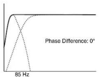
| Phase Difference | Value | | ---------------- | ----- | | 0° | 0 | | 85 Hz | 0 |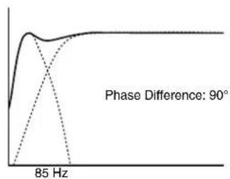
line
| Frequency | Phase Difference (°) | | --------- | -------------------- | | 85 Hz | 90 |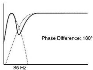
line
| Frequency | Phase Difference | | --------- | ---------------- | | 85 Hz | 180° |
line
| Frequency | Phase Difference | | --------- | ---------------- | | 85 Hz | 270° |Figure 3. The effect of phase difference between the subwoofer and the main monitors
Incorrect phase alignment can cause a drop in the audio level at the crossover frequency. Correct phase alignment eliminates this level dip. See chapter "Setting the Phase Switches."
The DIGITAL LFE switch selects the low pass frequency for the LFE signal (see "LFE CHANNEL" below). The possible frequencies are 85 Hz for "OFF" position and 120 Hz for "ON" position.
The LFE CHANNEL A/B selects which subframe is carrying the LFE signal. The position "ON" selects subframe A as the LFE signal route, position "OFF" selects subframe B. If subframe A is selected for LFE, subframe B is assumed to carry the main channel audio and vice versa.
The LFE +10 dB function increases the LFE channel level by +10 dB. See chapter "Using the LFE +10 dB function."
The LEVEL switches scale down the subwoofer output level. The switch settings are additive and they combine with the rotary level adjustment control.
The TEST TONE switch turns on the 85 Hz test tone. This tone is intended for manually calibrating the subwoofer phase. See chapter "Manual Phase Adjustment Method"
The ISS switch activates the signal sensing automatic energy saving function. This function puts the subwoofer in very low power consumption state when there is no input signal for a period of time.
The STORED switch selects the room acoustic compensation settings stored inside the memory of the subwoofer instead of the settings in the built-in DIP switches in the subwoofer. The stored settings can be created using the GLM Loudspeaker Manager Software and the GLM control network. The stored settings can provide superior flexibility and accuracy compared to the subwoofer's local user interface controls.
The ROTARY LEVEL CONTROL In addition to the LEVEL switches, the level of the subwoofer relative to the loudspeakers can be adjusted with this potentiometer.
Connector Panel Light
When used without a connection to the GLM software, the light on the connector panel is green, indicating normal operational mode. A red colour indicates amplifier clipping and yellow indicates thermal overload. If the red or yellow warning light appears, turn down the level.
Setting the Phase Switches
Incorrect phase alignment between main monitors and subwoofer can cause a drop in the audio level at the crossover frequency (see Figure 3).
The phase alignment between the main monitors and subwoofer depends on the listening position, the position of the subwoofer and the monitors in the room. The phase adjustment should be done only after the preferred positions are found and the subwoofer and monitor levels have been aligned.
The GLM software can adjust the phase automatically.
If the GLM is not available, the following manual phase matching can be applied.
Manual Phase Adjustment Method
The Genelec 7380A subwoofer is equipped

text_image
5 1 2 3 3 4 4Figure 4. Examples of subwoofer positioning. 1 and 2 are good starting positions for a single subwoofer and also work well with two linked subwoofers. Position 3 causes a significant bass boost and may cause asymmetric spatial imaging if only one subwoofer is used. Position 4 also works best with two subwoofers. Flush mounting (pos. 5) generally works well.
with a built-in 85 Hz frequency test tone generator for phase alignment at the fixed 85 Hz crossover frequency. Connect the monitor to the subwoofer's "TEST 1" output with a cable. Set the TEST TONE switch to "ON." Now, you hear an 85 Hz test tone through the subwoofer and the main monitor.
- Toggle the -180° phase switch on and off. Set it to the position giving the lowest sound level at the listening position.
- Toggle the -90^ phase switch on and off. Set it to the position giving the lowest sound level at the listening position.
- Finally, move the -180^ phase switch to the opposite setting. Deactivate the test signal. The phase adjustment is now complete.
Using the LFE +10 dB Function
The LFE channel is usually recorded 10 dB lower than the main channels so that there is 10 dB of extra level (headroom) available.
Most AV processors automatically add 10 dB to the LFE channel to restore the level in the LFE channel but some medium format mixing consoles and many smaller consoles do not have the facility to apply the +10 dB gain to the LFE. To overcome this limitation Genelec subwoofers provide a +10 dB LFE gain selectionchannels, this switch should be set to "OFF".
The "LFE +10 dB" function should not be used in the following cases:
- If the +10 dB LFE gain is already implemented by another device, for example, a surround sound processor or the output matrix of a mixing console.
- When producing an audio format that does not require the use of +10 dB gain on the LFE channel.
Additional Information
Positioning the Subwoofer in a Room
The location of the subwoofer can affect the frequency response and sound level dramatically particularly when the room acoustic effects are strong. Even small changes in a subwoofer's location can make a marked difference in the frequency response. To begin, place the subwoofer near the front wall slightly offset from the room center line. Often systematic experimentation is needed to find the location giving the flattest frequency response at the listening location. Usually the subwoofer is placed close to a wall as this creates the highest output. Positioning the subwoofer close to a corner will boost the bass level at lower frequencies and may also cause asymmetrical spatial imaging. Measured from the subwoofer's driver the recommended distance to a wall is less than 0.6 m (24 in). This avoids a loss of audio level at low frequencies created by the audio reflecting off the wall and cancelling certain frequencies radiated by the subwoofer.
Operating Environment
This subwoofer is designed for indoor use only. The permissible ambient temperature is 15-35 degrees Celsius (50-95°F) and relative humidity 20 - 80% (non-condensing). When the product has been stored or transported in a cool environment and is taken into a warm room, wait about one hour before opening packing to prevent condensation of humidity before connecting to mains power.
Minimum Clearances
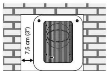
Do not cover the grille or place the subwoofer so that there is less than 0.1 m (4 in) of free space in front of the grille. The space must be ventilated or sufficiently large to dissipate heat so that the ambient temperature does not rise above 35 degrees Celsius (95°F). Make sure that the space under the subwoofer allows air flow. Thick carpets may block ventilation needed for cooling the electronics. The reflex port opening should have a clearance of at least 7.5 cm (3 in) to ensure functioning of the reflex port.
text_image
7,5 cm (3°)Figure 4. Flush mounting the subwoofer. Note the clearance needed on the reflex port side.
Flush Mounting
When the subwoofer is flush mounted in a wall or cabinet, ensure unrestricted airflow in the reflex port and amplifier cooling. Make the recess 7.5 cm (3 in) wider than the subwoofer. Place the subwoofer to the right side of the recess if the driver is facing the room. This leaves sufficient free space at the reflex port side. The height and depth of the recess should not be much bigger than what is needed for ventilation as this may cause unwanted acoustic effects.
Using Multiple Subwoofers
Multiple Genelec 7380A subwoofers can be coupled together in high SPL applications. The necessary cabling is different for digital and analog signals. When subwoofers are close to each other, the sound level increases typically by 6 dB for each doubling of the number of subwoofers. When subwoofers are far from each other, the total increase in the sound level can be less. It is safe to assume the increase is 3 dB for each doubling of the number of subwoofers. Accurate understanding of the increase in sound level requires acoustic measurements.
Digital Cabling
Run a signal cable from the AES/EBU OUT connector of the first subwoofer in the chain to the AES/EBU IN connector of the next subwoofer. Check that the Digital LFE and LFE Channel A/B control switches have the same settings in all subwoofers in the chain.
Analog Cabling
When daisy-chaining multiple subwoofers with analog signals, run a cable from the Link Out connector to the next subwoofer's Link In connector. When using the LFE signal, also run a cable from the LFE Out to the next subwoofer's LFE In.
line
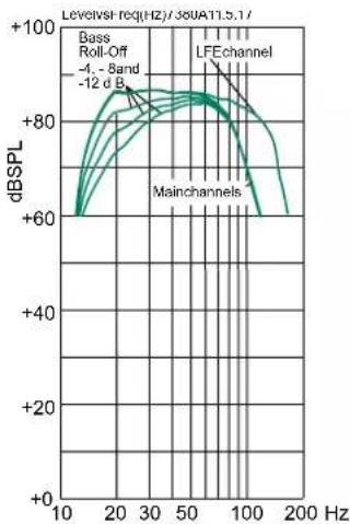
| Frequency (Hz) | dBSPL | | -------------- | ----- | | 10 | +60 | | 20 | +80 | | 30 | +85 | | 50 | +90 | | 100 | +85 | | 200 | +60 |Figure 5. The curves above show the main channel's frequency response with 85 Hz lowpass filtering, the frequency response of the LFE channel and the effect of the Bass Roll-Off adjustment to the response of the 7380A.
line
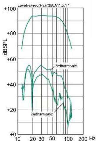
| Frequency (Hz) | dBSPL | | -------------- | ----- | | 10 | +70 | | 20 | +90 | | 30 | +95 | | 50 | +90 | | 100 | +60 | | 200 | +40 |Figure 6. The curves above show the harmonic distortion analysis of the 7380A in free field. In half space the SPL will be 6 dB higher.
Control Switch Settings When Using Multiple Subwoofers
We recommend using the GLM software and its AutoCal function for subwoofer calibration. Then, no manual adjustments on the subwoofer are necessary.
-
If the GLM is not available, manual adjustments can be done as follows: Calibrate subwoofers one by one. Turn on only one subwoofer at the time.
-
Calibrate the subwoofer level to match
the level the monitors. Monitors are usually also calibrated to deliver the same level at the listening position. Use the rotary level adjustment trimmer on the subwoofer and suitable test signals. Normally an octave wide pink noise signal located around 1 kHz is used for monitors and an octave wide pink noise around 40 Hz is used for the subwoofer. If you use a sound level meter, correct for the weighting – for example using A weighting in an SPL meter reduces the level reading for low frequencies relative to the mid frequencies. We recommend using an acoustical measurement system able to show the full frequency response for improved accuracy.
- Adjust the phase of the first subwoofer as instructed in the chapter "Manual Phase Adjustment Method".
- Repeat phases 1 to 3 with all other subwoofers in the chain, one by one.
- When two subwoofers connected in this way are positioned close to one another, bass level increases by 6 dB. Three subwoofers give an SPL increase of 9.5 dB and four subwoofers 12 dB compared to a single subwoofer. In order to match the SPL level of the complete subwoofer chain with the main monitor system, reduce the level of all subwoofers accordingly.
Maintenance
There are no user serviceable parts inside the subwoofer. Maintenance or repair must only be done by Genelec certified service personnel.
Guarantee
Genelec guarantees the subwoofers for two years against manufacturing faults or defects altering performance. You can extend the guarantee to five years by registering the product at www.genelec.com. Refer to the reseller for full sales and guarantee terms.
Safety Considerations
The 7380A has been designed in accordance with international safety standards. To ensure safe operation, the following warnings and precautions must be observed:
- Servicing and adjustment must only be performed by Genelec certified service personnel.
- The subwoofer enclosure must not be opened.
- Do not use this product with a mains cable or mains outlet having no protective earth (potential equalizing) connection as doing so may result in personal injury.
• To prevent fire or electric shock, do not expose the product to water or moisture. - Do not place objects filled with liquid, such as vases, on the subwoofer or near it.
- The amplifier is not completely disconnected from the mains power unless the mains cable is removed from the amplifier or the mains outlet.
- Free flow of air behind and around the subwoofer is necessary to maintain sufficient cooling. Do not obstruct airflow around the subwoofer.
- This subwoofer is capable of producing sound pressure levels in excess of 85 dB, which may cause a permanent hearing damage.
Compliance to FCC Rules
This device complies with part 15 of the FCC Rules. Operation is subject to the following two conditions:
- This device may not cause harmful interference, and
- This device must accept any interference received, including interference that may cause undesired operation.
Note: This equipment has been tested and found to comply with the limits for a Class B digital device, pursuant to part 15 of the FCC Rules. These limits are designed to provide reasonable protection against harmful interference in a residential installation. This equipment generates, uses and can radiate radio frequency energy and, if not installed and used in accordance with the instructions, may cause harmful interference to radio communications. However, there is no guarantee that interference will not occur in a particular installation. If this equipment does cause harmful interference to radio or television reception, which can be determined by turning the equipment off and on, the user is encouraged to try to correct the interference by one or more of the following measures:
- Reorient or relocate the receiving antenna.
- Increase the separation between the equipment and receiver.
- Connect the equipment into an outlet on a circuit different from that to which the receiver is connected.
- Consult the dealer or an experienced radio/TV technician for help.
Modifications not expressly approved by the manufacturer could void the user's authority to operate the equipment under FCC rules.
SPECIFICATIONS
| Model 7380A | |
| Lower cut-off frequency -6 dB 16 Hz | |
| Upper cut-off frequency -6 dB (main channel/LFE) 100 Hz/120 Hz | |
| Driver 381 mm (15 in) | |
| Harmonic distortion at 1 m on axis in half space, 30 to 85 Hz2nd3rd | ≤ 1% @ 100 dB SPL≤ 2% @ 100 dB SPL |
| Maximum short term sine wave SPL output averaged from 30 to 85 Hz, measured in half space at 1 meter | ≥ 119 dB SPL |
| Maximum peak SPL output with random pink noise, measured in half space at 1 meter | ≥ 123 dB SPL |
| Self generated noise at 1 m on axis (A-weighted) <5 dBA | |
| Weight 69 kg (152 lbs) | |
| Dimensions H x W x D 685 x 718 x 492 mm (27 | x 28 ^1/4 x 19 ^3/8 in) |
AMPLIFIER SECTION
| Short term amplifier output power(Long term output power is limited by driver unit protection circuitry) | 800 W |
| Amplifier system THD at nominal output | <0.01% |
| Mains voltage | 100-240 VAC 50/60 Hz |
| Power consumption | |
| Standby, ISS active | <2 W |
| Idle | 40 W |
| Full output, peak | 600 W |
SIGNAL PROCESSING SECTION
| Signal connectors 7.1 channel analog IN/OUT | Analog Link IN/OUTDigital AES/EBU IN/OUT |
| Analog signal input connector XLR female, balanced 10 kOhm | pin 1 gnd, pin 2 non-inverting, pin 3 inverting |
| Maximum analog input signal | +24.0 dBu |
| Analog input sensitivity (100 dB SPL at 1 m) | -6 dBu |
| Adjustment range (LEVEL dip switches + rotary level control) | +48 dBu to -6 dBu |
| Digital signal input connector XLR female 110 Ohm | AES/EBU Single Wire |
| Digital signal output / Thru connector XLR male 110 Ohm | AES/EBU Single Wire |
| Digital audio input | |
| Word length | 16 - 24 bits |
| Sample rate | 32 - 192 kHz |
| Digital input sensitivity (100 dB SPL at 1 m) | -30 dBFS |
| Digital input maximum attenuation | 48 dB |
| Positive input gain selection (GLM control) | +6, +12, +18 dB |
| Control network | |
| Type | Proprietary GLM network |
| Connection | 2 RJ45, CAT5 cables |
| GLMTMsoftware frequency response adjustment parametric notch filters 20 | |
| System calibration Genelec GLM AutoCalTM, GLM manual, Stand-alone | |
| Crossover setting in subwoofer's input/output channels | |
| Centralized Bass Management (for analog signal) | Input low pass fixed 85 Hz, output high pass fixed 85 Hz |
| Distributed Bass Management (GLM control) | Input low pass selectable 50 to 100 Hz, output no filtering |
| LFE cutoff 120 Hz | |
| Midband rejection >400 Hz ≥ 50 dB | |
| Bass Roll-Off control operating range in 4 dB steps 0 to -12 dB at 20 Hz | |
| Phase matching control | 90° steps with dip switch controls15° steps with GLM control |
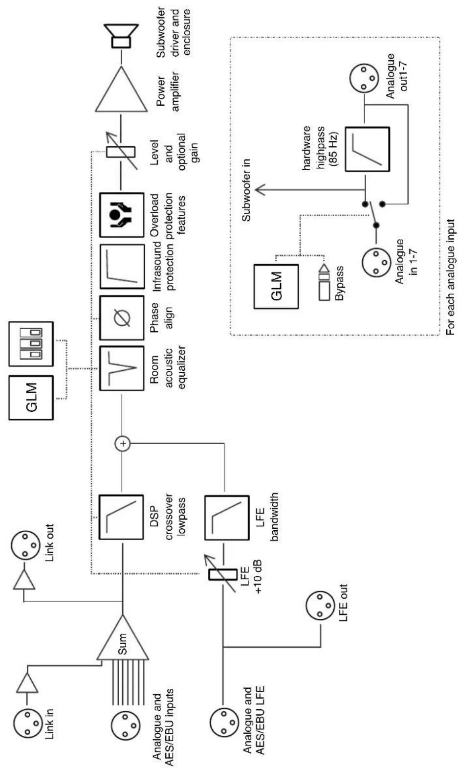
flowchart
graph TD
    A["Link in"] --> B["Sum"]
    C["Analogue and AES/EBU inputs"] --> B
    D["Analogue and AES/EBU LFE"] --> E["LFE +10 dB"]
    E --> F["LFE bandwidth"]
    F --> G["DSP crossover lowpass"]
    G --> H["+"]
    H --> I["Room acoustic equalizer"]
    I --> J["Phase align"]
    J --> K["Infrasound protection"]
    K --> L["Overload protection features"]
    L --> M["Level and optional gain"]
    M --> N["Power amplifier"]
    N --> O["Subwoofer driver and enclosure"]
    P["GLM"] --> Q["Block with bubble box"]
    R["Subwoofer in"] --> S["Hardware highpass (85 Hz)"]
    T["GLM"] --> U["Bypass"]
    V["Analogue in 1-7"] --> W["Analogue out1-7"]
    X["For each analogue input"] --> Y["Subwoofer in"]
Figure 7. The signal path block diagram of the 7380.
Genelec Document D0148R001. Copyright Genelec Oy 5.2017. All data subject to change without prior notice
GENELEC®
International enquiries:
Genelec, Olvitie 5
FIN-74100, Ilsalmi, Finland
Phone +358 17 83881
Fax +358 17 812 267
Email genelec@genelec.com
In the U.S. please contact:
Genelec, Inc., 7 Tech Circle
Natick, MA 01760, USA
Email sweden@genelec.com
In China please contact:
Beijing Genelec Audio Co.Ltd
B33 - 101
Universal Business Park
No. 10 Jiuxianqiao Road
Chaoyang District
100015 Beijing, China
Phone +86 400 700 19
Email genelec.china@genelec.com
www.genelec.com
In Japan
Genelec Japan Inc.
2-22-21 Akasaka, Minato-ku
07-0052, Tokyo
Phone +81-3-6441-0591
genelec.japan@genelec.com
Email genelec.japan@genelec.com