UPGT650EHMG - Tumble drier GE - Free user manual and instructions
Find the device manual for free UPGT650EHMG GE in PDF.

User questions about UPGT650EHMG GE
0 question about this device. Answer the ones you know or ask your own.
Ask a new question about this device
Download the instructions for your Tumble drier in PDF format for free! Find your manual UPGT650EHMG - GE and take your electronic device back in hand. On this page are published all the documents necessary for the use of your device. UPGT650EHMG by GE.
USER MANUAL UPGT650EHMG GE
Safety Instructions 2-5
Operating Instructions
Controls....6-8
Cycle Options 9-10
Dryer Features ....11
Loading and Using
the Dryer .....12, 13
Installation Instructions
Before You Begin....14-16
Connecting a Gas Dryer .....17–20
Connecting an
Electric Dryer 21-23
Exhausting the Dryer .....24-28
Final Setup 29,30
Reversing the Door Swing .....31, 32
Troubleshooting Tips ....33
Consumer Support
Consumer Support 36
Warranty (Canada) 35
Warranty (U.S.) 34
Owner's Manual and Installation Instructions
DPGT650
UPGT650
Write the model and serial numbers here:
Model # ____
Serial #
They are on the label on the front of the dryer behind the door.
▲WARNING!
For your safety, the information in this manual must be followed to minimize the risk of fire or explosion, electric shock, or to prevent property damage, personal injury, or death.
■Do not store or use gasoline or other flammable vapors and liquids in the vicinity of this or any other appliance.
■Installation and service must be performed by a qualified installer, service agency or the gas supplier.
WHAT TO DO IF YOU SMELL GAS:
Do not try to light a match, or cigarette, or turn on any gas or electrical appliance.
2 Do not touch any electrical switch; do not use any phone in your building.
3 Clear the room, building or area of all occupants.
4 Immediately call your gas supplier from a neighbor's phone. Follow the gas supplier's instructions carefully.
5 If you cannot reach your gas supplier, call the fire department.
California Safe Drinking Water and Toxic Enforcement Act
This act requires the governor of California to publish a list of substances known to the state to cause cancer, birth defects or other reproductive harm and requires businesses to warn customers of potential exposure to such substances.
Gas appliances can cause minor exposure to four of these substances, namely benzene, carbon monoxide, formaldehyde and soot, caused primarily by the incomplete combustion of natural gas or LP fuels.
Properly adjusted dryers will minimize incomplete combustion. Exposure to these substances can be minimized further by properly venting the dryer to the outdoors.
PROPER INSTALLATION
This dryer must be properly installed and located in accordance with the Installation Instructions before it is used. If you did not receive an Installation Instructions sheet, you can receive one by visiting ge.com, or by calling 800.GE.CARES (800.432.2737).
■Properly ground dryer to conform with all governing codes and ordinances. Follow details in Installation Instructions.
■Install or store where it will not be exposed to temperatures below freezing or exposed to the weather.
■Connect to a properly rated, protected and sized power supply circuit to avoid electrical overload.
■Remove the colored protective film from both the control panel and the door.
■Remove all sharp packing items and dispose of all shipping materials properly.
■Do not remove the vent protector from the back of the dryer (on some models).
■Pull the protector out and down to its lowest position and connect the exhaust duct to the dryer. The lowered protector will prevent the duct from getting crushed (on some models).
Exhaust/Ducting:
1 Dryers MUST be exhausted to the outside to prevent large amounts of moisture and lint from being blown into the room.
2 Use only rigid metal or flexible metal 4" diameter ductwork inside the dryer cabinet or for exhausting to the outside. USE OF PLASTIC OR OTHER COMBUSTIBLE DUCTWORK CAN CAUSE A FIRE. PUNCTURED DUCTWORK CAN CAUSE A FIRE IF IT COLLAPSES OR BECOMES OTHERWISE RESTRICTED IN USE OR DURING INSTALLATION.
For complete details, follow the Installation Instructions.
▲WARNING!
YOUR LAUNDRY AREA
■Keep the area underneath and around your appliances free of combustible materials (lint, paper, rags, etc.), gasoline, chemicals and other flammable vapors and liquids.
- Keep the floor around your appliances clean and dry to reduce the possibility of slipping.
■Close supervision is necessary if this appliance is used by or near children. Do not allow children to play on, with or inside this or any other appliance.
- Keep all laundry aids (such as detergents, bleaches, etc.) out of the reach of children, preferably in a locked cabinet. Observe all warnings on container labels to avoid injury.
■Never climb on or stand on the dryer top.

WHEN USING YOUR DRYER
■Never reach into the dryer while the drum is moving. Before loading, unloading or adding clothes, wait until the drum has completely stopped.
■Clean the lint filter before each load to prevent lint accumulation inside the dryer or in the room. DO NOT OPERATE THE DRYER WITHOUT THE LINT FILTER IN PLACE.
■Do not wash or dry articles that have been cleaned in, washed in, soaked in or spotted with combustible or explosive substances (such as wax, oil, paint, gasoline, degreasers, dry-cleaning solvents, kerosene, etc.) which may ignite or explode. Do not add these substances to the wash water. Do not use or place these substances around your washer or dryer during operation.
■Do not place items exposed to cooking oils in your dryer. Items contaminated with cooking oils may contribute to a chemical reaction that could cause a clothes load to catch fire.
■ Any article on which you have used a cleaning solvent or that contains flammable materials (such as cleaning cloths, mops, towels used in beauty salons, restaurants or barber shops, etc.) must not be placed in or near the dryer until solvents or flammable materials have been removed. There are many highly flammable items used in homes such as acetone, denatured alcohol, gasoline, kerosene, some household cleaners, some spot removers, turpentines, waxes, wax removers and products containing petroleum distillates.
■The laundry process can reduce the flame retardancy of fabrics. To avoid such a result, carefully follow the garment manufacturer's care instructions.
■Do not dry articles containing rubber, plastic, foam or similar materials such as padded bras, tennis shoes, galoshes, bath mats, rugs, bibs, baby pants, plastic bags, pillows, etc., that may melt or burn. Some rubber materials, when heated, can under certain circumstances produce fire by spontaneous combustion.
■Do not store plastic, paper or clothing that may burn or melt on top of the dryer during operation.
Garments labeled Dry Away from Heat or Do Not Tumble Dry (such as life jackets containing kapok) must not be put in your dryer.
■Do not dry fiberglass articles in your dryer. Skin irritation could result from the remaining particles that may be picked up by clothing during subsequent dryer uses.
To minimize the possibility of electric shock, unplug this appliance from the power supply or disconnect the dryer at the building's distribution panel by removing the fuse or switching off the circuit breaker before attempting any maintenance or cleaning (except the removal and cleaning of the lint filter). NOTE: Pressing START, PAUSE or POWER does NOT disconnect the appliance from the power supply.

WHEN USING YOUR DRYER (cont.)
■ Never attempt to operate this appliance if it is damaged, malfunctioning, partially disassembled, or has missing or broken parts, including a damaged cord or plug.
■The interior of the machine and the exhaust duct connection inside the dryer should be cleaned at least once a year by a qualified technician. See the Loading and Using the Dryer section.
If yours is a gas dryer, it is equipped with an automatic electric ignition and does not have a pilot light. DO NOT ATTEMPT TO LIGHT WITH A MATCH. Burns may result from having your hand in the vicinity of the burner when the automatic ignition turns on.
■You may wish to soften your laundered fabrics or reduce the static electricity in them by using a dryer-applied fabric softener or an anti-static conditioner. We recommend you use either a fabric softener in the wash cycle, according to the manufacturer's instructions for those products, or try a dryer-added product for which the manufacturer gives written assurance on the package that their product can be safely used in your dryer. Service or performance problems caused by use of these products are the responsibility of the manufacturers of those products and are not covered under the warranty to this appliance.

WHEN NOT USING YOUR DRYER
■Grasp the plug firmly when disconnecting this appliance to avoid damage to the cord while pulling. Place the cord away from traffic areas so it will not be stepped on, tripped over or subjected to damage.
■ Do not attempt to repair or replace any part of this appliance or attempt any servicing unless specifically recommended in this Owner's Manual or in published user-repair instructions that you understand and have the skills to carry out.
■Before discarding a dryer, or removing it from service, remove the dryer door to prevent children from hiding inside.
■ Do not tamper with controls.

READ AND FOLLOW THIS SAFETY INFORMATION CAREFULLY.
SAVE THESE INSTRUCTIONS
About the dryer control panel.
Control Panel
Throughout this manual, features and appearance may vary from your model.

text_image
POWER 1 6 4 5 3 2 7 Sensor Dry COTIONS ULTRA DELICATES MIXED LOAD WIRWILE FREE ACTIVE WEAR DELICATES MANUAL DRY SPEED DRY DEWRINKLE AIR DRY Cycles PAUSE1 Power
Press to "wake up" the display. If the display is active, press to put the dryer in the idle mode.
NOTE: Pressing POWER does not disconnect the appliance from the power supply.
2 Cycles
The cycle controls the length and tumble speed of the drying process. The chart below will help you match the dry setting with the loads.
Sensor Cycles
| COTTONS For cottons and most linens. | |
| MIXED LOAD For loads consisting of cottons and poly-blends. | |
| WRINKLE FREE For wrinkle-free and permanent press items. | |
| ACTIVE WEAR | Clothing worn for active sports exercise and some casual wear. Fabrics include new technology finishes and stretch fibers such as Spandex. |
| DELICATES For lingerie and special-care fabrics. | |
| ULTRA DELICATES For delicate fabrics. | |
Manual Dry Cycles
| SPEED DRY | For small loads that are needed in a hurry, such as sports or school uniforms. Can also be used if the previous cycle left some items damp, such as collars or waistbands. |
| DEWRINKLE | For removing wrinkles from items that are dry or slightly damp. This cycle is not recommended for delicate fabrics. |
| AIR DRY Use this feature to tumble items without heat. | |
| My Cycles (on some models) | |
| MY CYCLES Press to use, create or modify custom dry cycles. | |
3 Time Dry
Use to set your own dry time. TIME DRY is also recommended for small loads.
To use TIME DRY:
- Press the TIME DRY button until the amount of time you want is selected.
- Select the temperature by pressing the TEMP button.
- Close the door.
- Press the START/PAUSE button.
4 Dry Level
The sensor continuously monitors the amount of moisture in the load. When the moisture in your clothes reaches your selected dry level, the dryer will stop.
VERY DRY Use for heavy fabrics.
MORE DRY Use for heavy or mixed type of fabrics.
NORMAL Use for normal dryness level suitable for most loads. This is the preferred cycle for energy saving.
LESS DRY Use for lighter fabric (ideal for ironing).
DAMP DRY For leaving items partially damp.
About the dryer control panel (cont.).

TEMP
You can change the temperature of your dry cycle.
HIGH For regular to heavy cottons.
MEDIUM HIGH For regular cottons.
MEDIUM For synthetics, blends and items labeled permanent press.
LOW For delicates, synthetics and items labeled Tumble Dry Low.
EXTRA LOW For lingerie and special-care fabrics.

My Cycles
Set up your favorite combination of settings and save them here for one touch recall. These custom settings can be set while a cycle is in progress.
To store a MY CYCLES combination of settings:
- Select your drying cycle.
- Change TEMP and DRY LEVEL settings to fit your needs.
- Select any drying OPTIONS you want.
- Press and hold the pad for three seconds to store your selection. A beep will sound and the pad will light up.
To recall your stored MY CYCLES combination:
Press the MY CYCLES button before drying a load.
To change your stored MY CYCLES combination:
Follow steps 1-4 in "To store a MY CYCLES combination of settings".

START
Press to start a dry cycle. If the dryer is running, press it once and it will pause the dryer. Press it again to restart the dryer cycle.
About cycle options.
NOTE: Not all features are available on all dryer models. ge.com
 | Wrinkle CareTumbles the drum without heat for 10 seconds every 5 minutes for up to 3 hours.The dryer will display a "racetrack" on the display during the Wrinkle Care phase.Wrinkle care shuts off automatically when the door is opened. | |
 | SignalAlerts you that the cycle is complete.The clothes should be removed when the beeper goes off so wrinkles don't set in. | Press SIGNAL to select low or high volume, or to turn the beeper off.The beeper will continue to sound every 2 minutes (maximum of 4 times). |
 | MORE TIMEIncreases the dry time in 1-minute increments, up to 99 minutes. | |
 | LESS TIMEDecreases the dry time in 1-minute increments, down to 10 minutes. |
About cycle options. NOTE: Not all features are available on all dryer models.

text_image
DRY LEVEL TEMP HOLD 3 SEC to LOCK CONTROLLock
You can lock the controls to prevent any selections from being made. Or you can lock the controls after you have started a cycle.
Children cannot accidentally start the dryer by touching pads with this option selected.
To lock the dryer, press and hold the DRY LEVEL and TEMP buttons at the same time for 3 seconds. To unlock the dryer, press and hold the DRY LEVEL and TEMP buttons for 3 seconds.
When the lock function is enabled, CL will blink in the display with the estimated time remaining.

Estimated Time Remaining
Displays the approximate time remaining until the end of the cycle.
As the cycle begins, you will see an initial approximate total cycle time in the display. Then lights will "race" in the display. This means the dryer is continuously monitoring
the amount of moisture in the load. The lights will continue until the dryer senses a low level of moisture in the load. At that point, the dryer will calculate and display the approximate time remaining.

My Cycles
To save a favorite cycle, set the desired settings and hold down the MY CYCLES button for 3 seconds. A beep will sound to indicate the cycle has been saved.
To use your custom cycle, press the MY CYCLES button before drying a load.
To change the saved cycle, set the desired settings and hold down the MY CYCLES button for 3 seconds.
See page 8 for more details.
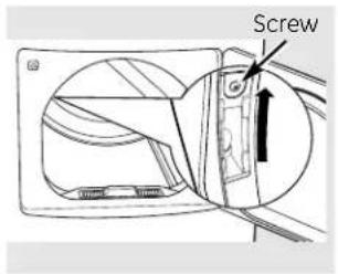
text_image
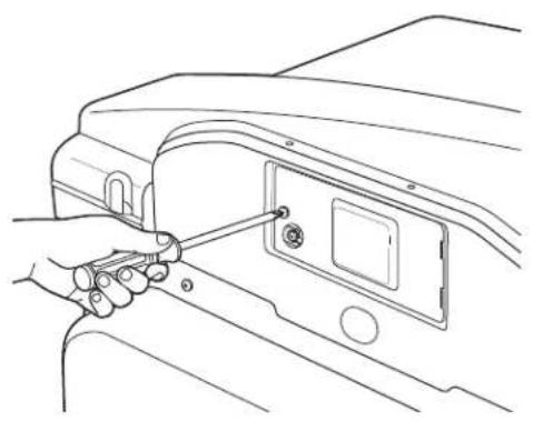
ScrewChanging the Drum Lamp
Before replacing the drum lamp, be sure to unplug the dryer power cord or disconnect the dryer at the household distribution panel by removing the fuse or switching off the circuit breaker.
The drum lamp is located at the top left of the door frame.
1 Remove the screw holding the drum lamp shield in place.
2 Slide the shield up and remove.
3 Remove the bulb and replace with a 15-watt, 120-volt candelabra-base bulb.
4 Replace the lamp shield and screw.
natural_image
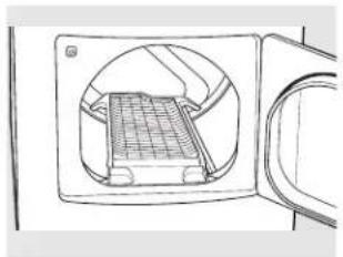
Technical line drawing of a mechanical component with internal grid structure (no text or symbols)Using the Drying Rack
A handy drying rack may be used for drying delicate items such as washable sweaters.
Hook the rack over the lint filter so the rack extends into the dryer drum.
NOTE:
- The drying rack should only be used with the TIME DRY cycle. It is also strongly recommended when drying sneakers.
- Do not use this drying rack when there are other clothes in the dryer.
Loading and Using the Dryer.
Always follow fabric manufacturer's care label when laundering.
Sorting and Loading Hints
As a general rule, if clothes are sorted properly for the washer, they are sorted properly for the dryer. Try also to sort items according to size. For example, do not dry a sheet with socks or other small items.
Do not add fabric softener sheets once the load has become warm. They may cause fabric softener stains. Bounce® Fabric Conditioner Dryer Sheets have been approved for use in all GE Dryers when used in accordance with the manufacturer's instructions.
Do not overload. This wastes energy and causes wrinkling.
Do not dry the following items:
fiberglass items, woolens, rubber-coated items, plastics, items with plastic trim and foam-filled items.
Fabric Care Labels
Below are fabric care label "symbols" that affect the clothing you will be laundering.
Dry Labels
Tumble dry

Dry

Normal

Permanent Press/wrinkle resistant

Gentle/ delicate

Do not tumble dry

Do not dry (used with do not wash)
Heat setting

High

Medium

Low

No heat/air
Special instructions

Line dry/ hang to dry

Drip dry

Dry flat

In the shade

natural_image
Line drawing of a device interior with a lid and handle, no text or symbols presentCare and Cleaning of the Dryer
Dryer Interior and Duct: The interior of the appliance and exhaust duct should be cleaned once a year by qualified service personnel.
The Exterior: Wipe or dust any spills or washing compounds with a damp cloth. Dryer control panel and finishes may be damaged by some laundry pretreatment soil and stain remover products. Apply these products away from the dryer. The fabric may then be washed and dried normally. Damage to your dryer caused by these products is not covered by your warranty.
Do not touch the surface or the display with sharp objects.
The Lint Filter: Clean the lint filter before each use. Remove by pulling straight up. Run your fingers across the filter. A waxy buildup may form on the lint filter from using dryer-added fabric softener sheets. To remove this buildup, wash the lint screen in warm, soapy water. Dry thoroughly and replace. Do not operate the dryer without the lint filter in place.
Vacuum the lint from the dryer lint filter area if you notice a change in dryer performance.
Stainless Steel: To clean stainless steel surfaces, use a damp cloth with a mild, nonabrasive cleaner suitable for stainless steel surfaces. Remove the cleaner residue, and then dry with a clean cloth.
The stainless steel used to make the dryer drum provides the highest reliability available in a GE dryer. If the dryer drum should be scratched or dented during normal use, the drum will not rust or corrode. These surface blemishes will not affect the function or durability of the drum.
The Exhaust Hood: Check with a mirror that the inside flaps of the hood move freely when operating. Make sure that there is no wildlife (birds, insects, etc.) nesting inside the duct or hood.
Installation Dryer Instructions
DPGT650 and UPGT650
Questions? Call 800.GE.CARES (800.432.2737) or visit our Web site at: ge.com
In Canada, call 1.800.561.3344, or visit geappliances.ca
BEFORE YOU BEGIN
Read these instructions completely and carefully.
- IMPORTANT – Save these instructions for local electrical inspector's use.
- IMPORTANT – Observe all governing codes and ordinances.
- Note to Installer – Be sure to leave these instructions with the Consumer.
- Note to Consumer – Keep these instructions for future reference.
- This dryer must be exhausted to the outdoors.
- Before the old dryer is removed from service or discarded, remove the dryer door.
- Service information and the wiring diagram are located in the control console.
- Do not allow children on or in the appliance. Close supervision of children is necessary when the appliance is used near children.
- Proper installation is the responsibility of the installer.
- Product failure due to improper installation is not covered under the Warranty.
- Gas dryers are not approved for mobile home installation.
FOR YOUR SAFETY:
WARNING
- Use only rigid metal or flexible metal 4-inch diameter ductwork for exhausting to the outdoors. Never use plastic or other combustible easy-to-puncture ductwork.
- This appliance must be properly grounded and installed as described in these instructions.
- Do not install or store appliance in an area where it will be exposed to water and/or weather.
- The National Fuel Gas Code restricts installations of gas appliances in garages. They must be 18 inches off the ground and protected by a barrier from vehicles.
- Install the dryer where the temperature is above 50^ for satisfactory operation of the dryer control system.
NOTE: Installation and service of this dryer must be performed by a qualified installer, service agency or the gas supplier.
In the Commonwealth of Massachusetts:
- This product must be installed by a licensed plumber or gas fitter.
- When using ball-type gas shut-off valves, they shall be T-handle-type.
- A flexible gas connector, when used, must not exceed 3 feet.
UNPACKING YOUR DRYER
Tilt the dryer sideways and remove the foam shipping pads by pulling at the sides and breaking them away from the dryer legs. Be sure to remove all of the foam pieces around the legs.
Remove the bag containing the drying rack, literature and serial cable.

natural_image
Simple line drawing of a kitchen appliance with directional arrows indicating motion (no text or symbols)IMPORTANT: Gas dryers are not approved for mobile home installation.
MINIMUM CLEARANCE OTHER THAN ALCOVE OR CLOSET INSTALLATION
Minimum clearance to combustible surfaces and for air openings are:
- 0 inch clearance both sides
- 1 inch front
- 3 inches rear
Consideration must be given to provide adequate clearance for proper operation and service.
DRYER DIMENSIONS

text_image
Front View 43 7/8" (111.4 cm) 27" (68.6 cm)
text_image
Side View 35½" (90.2 cm) 37¼" (94.6 cm) 51" (129.5 cm) 29" (73.7 cm)- Your dryer is approved for installation in an alcove or closet, as stated on a label on the dryer back.
- The dryer MUST be vented to the outdoors. See the EXHAUST INFORMATION section.
- Minimum clearance between dryer cabinet and adjacent walls or other surfaces is:
0" either side 3" front and rear - Minimum vertical space from floor to overhead shelves, cabinets, ceilings, etc., is 52".
- Closet doors must be louvered or otherwise ventilated and have at least 60 square inches of open area equally distributed. If the closet contains both a washer and a dryer, doors must contain a minimum of 120 square inches of open area equally distributed.
- No other fuel-burning appliance shall be installed in the same closet with the dryer (gas models only).
BATHROOM OR BEDROOM INSTALLATION
- The dryer MUST be vented to the outdoors. See EXHAUST INFORMATION.
- The installation must conform with local codes or, in the absence of local codes, with the NATIONAL ELECTRICAL CODE, ANSI/NFPA NO. 70 (for electric dryers) or NATIONAL FUEL GAS CODE, ANSI Z223 (for gas dryers).
CONNECTING A GAS DRYER (skip for electric dryers)
TOOLS AND MATERIALS YOU WILL NEED FOR CONNECTING THE GAS SUPPLY
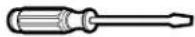
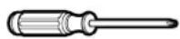
☐ Flat- or straight-blade screwdriver (may be needed for cord strain relief)
☐Flexible stainless steel or plastic-coated brass connecting tube (if allowed by building code)

natural_image
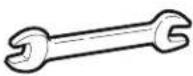
Line drawing of a flexible hose with threaded ends and flanged ends (no text or symbols)□Open-end wrenches for flexible tube and connector
☐Adjustable pliers (to adjust leveling legs)
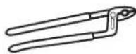
☐ Pipe wrench for holding dryer gas inlet while attaching adapter elbow
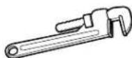
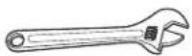
☐Adjustable wrenches (2) for tightening connections
FOR YOUR SAFETY:
WARNING
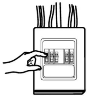
Before beginning the installation, turn off the circuit breaker(s) or remove the dryer's circuit fuse(s) at the electrical box. Be sure the dryer cord is unplugged from the wall.

natural_image
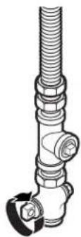
Hand placing a panel into an electrical outlet with wires (no text or symbols visible)Turn the dryer's gas shutoff valve in the supply line to the OFF position.

text_image
Shutoff ValveDisconnect and discard old flexible gas connector and ducting material.

natural_image
Simple line drawing of a trash bin with a downward arrow and trash tube (no text or symbols)CONNECTING A GAS DRYER (cont.)
GAS REQUIREMENTS
WARNING
- Installation must conform to local codes and ordinances, or in their absence, the NATIONAL FUEL GAS CODE, ANSI Z223.
- This gas dryer is equipped with a Valve and Burner Assembly for use only with natural gas. Using conversion kit WE25X10014, your local service organization can convert this dryer for use with propane (LP) gas. ALL CONVERSIONS MUST BE MADE BY PROPERLY TRAINED AND QUALIFIED PERSONNEL AND IN ACCORDANCE WITH LOCAL CODES AND ORDINANCE REQUIREMENTS.
- The dryer must be disconnected from the gas supply piping system during any pressure testing of that system at a test pressure in excess of 0.5 PSI (3.4 KPa).
- The dryer must be isolated from the gas supply piping system by closing the equipment shut-off valve during any pressure testing of the gas supply piping of test pressure equal to or less than 0.5 PSI (3.4KPa).
GAS SUPPLY
- A 1/8" National Pipe Taper thread plugged tapping, accessible for test gauge connection, must be installed immediately upstream of the gas supply connection to the dryer. Contact your local gas utility should you have questions on the installation of the plugged tapping.
- Supply line is to be 1/2" rigid pipe and equipped with an accessible shutoff within 6 feet of, and in the same room with, the dryer.
- Use pipe compound appropriate for natural or LP gas or use Teflon® tape.
- Connect flexible metal connector to dryer and gas supply.
IN THE COMMONWEALTH OF MASSACHUSETTS
- This product must be installed by a licensed plumber or gas fitter.
- When using ball-type gas shut-off valves, they shall be the T-handle type.
- A flexible gas connector, when used, must not exceed 3 feet.
DRYER GAS SUPPLY CONNECTION
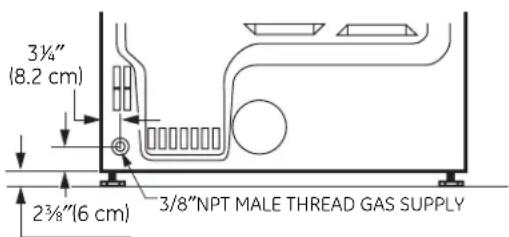
text_image
3½" (8.2 cm) 2¾"(6 cm) 3/8"NPT MALE THREAD GAS SUPPLYNOTE: Add to vertical dimension the distance between cabinet bottom to floor.
CONNECTING THE DRYER TO THE GAS SUPPLY
A Install a female 3/8"NPT elbow at the end of the dryer gas inlet. Install a 3/8"flare union adapter to the female elbow.
IMPORTANT: Use a pipe wrench to securely hold on to the end of the dryer gas inlet to prevent twisting the inlet.
NOTE: Apply pipe compound or Teflon® tape to the threads of the adapter and dryer gas inlet.
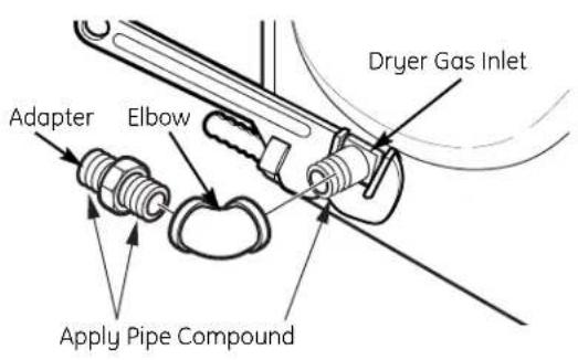
text_image
Dryer Gas Inlet Adapter Elbow Apply Pipe CompoundB Attach the flexible metal gas line connector to the adapter.
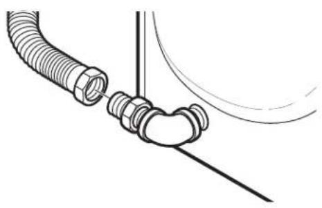
natural_image
Technical line drawing of a mechanical assembly with threaded connectors and a curved component (no text or symbols)C Tighten the flexible gas line connection using two adjustable wrenches.
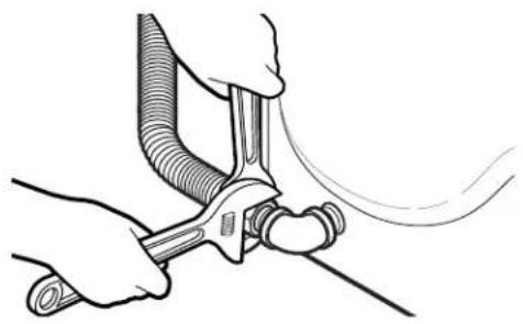
natural_image
Illustration of hands using a tool to lift or lift a pipe (no text or symbols present)CONNECTING THE DRYER TO THE GAS SUPPLY (cont.)
D Install a 1/8"NPT plugged tapping to the dryer gas line shut-off valve for checking gas inlet pressure.
Install a flare union adapter to the plugged tapping.
NOTE: Apply pipe compound or Teflon® tape to the threads of the adapter and plugged tapping.
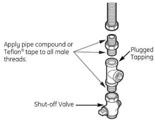
text_image
Apply pipe compound or Teflon® tape to all male threads. Plugged Tapping Shut-off ValveE Tighten all connections using two adjustable wrenches. Do not overtighten.

natural_image
Illustration of hands connecting a mechanical pipe to a valve (no text or symbols present)F Open the gas shutoff valve.
CONNECTING A GAS DRYER (cont.)
TEST FOR LEAKS
⚠ WARNING – Never use an open flame to test for gas leaks.
Check all connections for leaks with soapy solution or equivalent.
Apply a soap solution. The leak test solution must not contain ammonia, which could cause damage to the brass fittings.
If leaks are found, close the valve, retighten the joint and repeat the soap test.
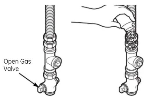
text_image
Open Gas ValveELECTRICAL CONNECTION INFORMATION FOR GAS DRYERS
A WARNING - To reduce the risk of fire, electrical shock and personal injury:
- Do not use an extension cord or an adapter plug with this appliance.
- The dryer must be electrically grounded in accordance with local codes and ordinances, or in the absence of local codes, in accordance with the NATIONAL ELECTRICAL CODE, ANSI/NFPA NO. 70.
ELECTRICAL REQUIREMENTS FOR GAS DRYERS
This appliance must be supplied with 120V, 60Hz, and connected to a properly grounded branch circuit, protected by a 15- or 20-amp circuit breaker or time-delay fuse.
If electrical supply provided does not meet the above specifications, it is recommended that a licensed electrician install an approved outlet.
WARNING – This dryer is equipped with a three-prong (grounding) plug for your protection against shock hazard and should be plugged directly into a properly grounded three-prong receptacle. Do not cut or remove the grounding terminal from this plug.
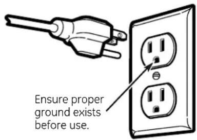
text_image
Ensure proper ground exists before use.If local codes permit, an external ground wire (not provided), which meets local codes, may be added by attaching to the green ground screw on the rear of the dryer, and to an alternate established ground.
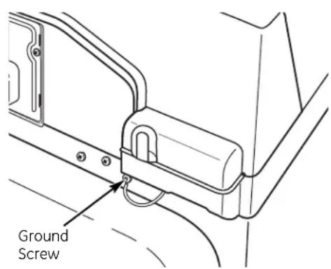
text_image
Ground ScrewCONNECTING AN ELECTRIC DRYER (skip for gas dryers)
TOOLS AND MATERIALS YOU WILL NEED FOR CONNECTING THE ELECTRICAL SUPPLY
☐ Flat- or straight-blade screwdriver (may be needed for cord strain relief)

☐#2 Phillips-head screwdriver (for terminal connections)
☐UL-listed strain relief (may be supplied with cord)
□UL-listed power cord
- 30-amp
-240V -
10 AWG minimum copper conductor
- Closed-loop or forked terminals with upturned ends
- 3-wire (for construction before 1996) or 4-wire (for construction after 1996)

natural_image
Pure electrical circuit lines without any symbolsFOR YOUR SAFETY:
WARNING
Before making the electrical connection, turn off the circuit breaker(s) or remove the dryer's circuit fuse(s) at the electrical box. Be sure the dryer cord is unplugged from the wall. NEVER LEAVE THE ACCESS COVER OFF THE TERMINAL BLOCK.
natural_image
Hand placing a panel into an electrical outlet with wires (no text or symbols visible)ELECTRICAL CONNECTION INFORMATION FOR ELECTRIC DRYERS
A WARNING - To reduce the risk of fire, electrical shock and personal injury:
- Do not use an extension cord or an adapter plug with this appliance.
- The dryer must be electrically grounded in accordance with local codes and ordinances, or in the absence of local codes, in accordance with the NATIONAL ELECTRICAL CODE, ANSI/NFPA NO. 70.
CONNECTING AN ELECTRIC DRYER (cont.)
ELECTRICAL REQUIREMENTS FOR ELECTRIC DRYERS
This dryer must be connected to an individual branch circuit, protected by the required time-delay fuses or circuit breakers. A three- or four-wire, single phase, 120/240V or 120/208V, 60Hz, 30-amp circuit is required.
If the electric supply does not meet the above specifications, then call a licensed electrician.
GROUNDING INSTRUCTIONS
This dryer must be connected to a grounded metal, permanent wiring system, or an equipment-grounding conductor must be run with the circuit conductors and connected to the equipment grounding terminal on the appliance.
NOTE: Since January 1, 1996, the National Electrical Code requires that new constructions utilize a 4-wire connection to an electric dryer. A 4-wire cord must also be used where local codes do not permit grounding through the neutral. 3-wire connection is NOT for use on new construction.
A Remove the terminal block access cover located at the upper back.
natural_image
Line drawing of a hand inserting a cable into a device panel (no text or symbols)For 3-wire and 4-wire Connection: Install a UL-listed strain relief into the power cord entry hole beneath the terminal block. Thread a UL-listed 30A, 240V, 3-wire or 4-wire, #10 AWG minimum copper conductor power cord through the strain relief.

text_image
Strain Relief(3-wire Connection Shown)
C For 3-wire and 4-wire Connection: Connect the two hot lines to the outer screws of the terminal block.
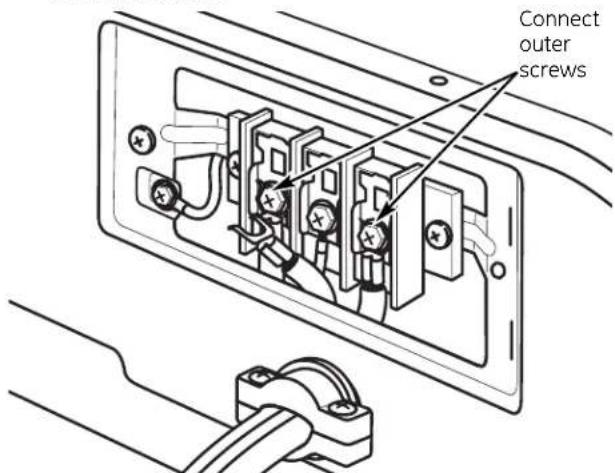
text_image
Connect outer screws(3-wire Connection Shown)
WARNING: Do not make a sharp bend or crimp wiring/conductor at connections.
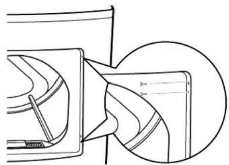
D For 3-wire Connection ONLY:
Be sure the dryer's green ground wire is connected to green ground screw on cabinet rear.
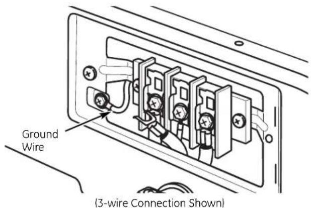
text_image
Ground Wire (3-wire Connection Shown)For 4-wire Connection ONLY:
Remove the dryer's ground wire from behind the green ground screw and connect it to the center screw of the terminal block.
Attach ground wire of power cord to the cabinet with the green ground screw.

text_image
Power Cord Ground Wire (4-wire Connection Shown)E For 3-wire and 4-wire Connection: Connect the neutral (center line on 3-wire, white line on 4-wire) line to the center of terminal block.

text_image
Connect center screw (3-wire Connection Shown)For 3-wire and 4-wire Connection: Tighten all terminal block screws completely.

natural_image
Diagram of a wire connection showing two electrical outlets with a cable inserted, no text or symbols presentFor 3-wire and 4-wire Connection: Reinstall the terminal block access cover. IMPORTANT: Do not leave the access cover off.
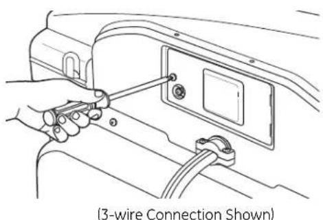
natural_image
Line drawing of a hand holding a tool to switch a panel inside a vehicle (no text or symbols)EXHAUSTING THE DRYER

WARNING – To reduce the risk of fire or personal injury:
- This dryer must be exhausted to the outdoors.
- Use only metal duct.
- Do not terminate exhaust in a chimney, any gas vent, under an enclosed floor (crawl space) or into an attic. The accumulated lint could create a fire hazard.
- Provide an access for inspection and cleaning of the exhaust system, especially at turns. Inspect and clean at least once a year.
- Never terminate the exhaust into a common duct with a kitchen exhaust. A combination of lint and grease could create a fire hazard.
- Do not obstruct incoming or exhausted air.
TOOLS AND MATERIALS YOU WILL NEED TO INSTALL EXHAUST DUCT
Phillips-head screwdriver
☐Duct tape or duct clamp
☐ Rigid or UL-listed flexible metal 4" (10.2 cm) duct

□Vent hood
EXHAUST SYSTEM CHECKLIST
HOOD OR WALL CAP
- Terminate in a manner to prevent back drafts or entry of birds or other wildlife.
- Termination should present minimal resistance to the exhaust airflow and should require little or no maintenance to prevent clogging.
- Never install a screen in or over the exhaust duct.
- Wall caps must be installed at least 12" above ground level or any other obstruction with the opening pointed down.
- If roof vents or louvered plenums are used, they must be equivalent to a 4" dampened wall cap in regard to resistance to airflow, prevention of back drafts and maintenance required to prevent clogging.
SEPARATION OF TURNS
- For best performance, separate all turns by at least 4 ft. of straight duct, including distance between last turn and dampened wall cap. For turns less than 4 ft. apart, see the Ducting Component Equivalency Chart.
SEALING OF JOINTS
- All joints should be tight to avoid leaks. The male end of each section of duct must point away from the dryer.
- Do not assemble the ductwork with fasteners that extend into the duct. They will serve as a collection point for lint.
- Duct joints should be made air- and moisture-tight by wrapping the overlapped joints with duct tape or aluminum tape.
- Horizontal runs should slope down toward outdoors 1/4" per foot.
INSULATION
- Ductwork that runs through an unheated area or is near air conditioning should be insulated to reduce condensation and lint buildup.
USING FLEXIBLE METAL DUCT FOR TRANSITION VENTING
Rigid or semi-rigid metal ducting is recommended for use as transition ducting between the dryer and the wall. In special installations when it is impossible to make a connection with the above recommendations, then a UL-listed flexible metal transition duct may be used between the dryer and wall connection only. The use of this ducting will affect dry time.
If flexible metal transition duct is necessary, the following directions must be followed:
- Use the shortest length possible.
- Stretch the duct to its maximum length.
- Do not crush or collapse.
- Never use flexible metal ducting inside the wall or inside the dryer.
- Avoid resting the duct on sharp objects.
- Venting must conform to local building codes.
FOR TRANSITION VENTING (DRYER TO WALL), DO:
natural_image
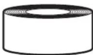
Technical line drawing of a mechanical device with no visible text or symbols- DO cut duct as short as possible and install straight into wall.
text_image
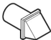
•DC wh ne Elbows• DO use elbows when turns are necessary.
DO NOT:

natural_image
Pure geometric diagram with intersecting lines and shapes, no text or symbols present•DO NOT bend or collapse ducting. Use elbows if turns are necessary.
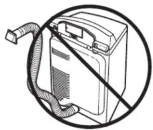
natural_image
Diagram of a battery with a hose and no visible text or symbols•DO NOT use excessive exhaust length. Cut duct as short as possible.

natural_image
Simple line drawing of a mechanical component with a diagonal line and arrow, no text or symbols present.•DO NOT crush duct against the wall.

natural_image
Pure technical diagram showing a diagonal line intersecting a vertical structure with an arrow, no text or symbols present.•DO NOT set dryer on duct.
EXHAUSTING THE DRYER (cont.)
WARNING
USE ONLY METAL 4" DUCT. DO NOT USE DUCT LONGER THAN SPECIFIED IN THE EXHAUST LENGTH TABLE.
Ducting longer than 90 equivalent feet will:
- Increase the drying times and the energy cost.
- Reduce the dryer life.
- Accumulate lint, creating a potential fire hazard.
EXAMPLE ONLY
The following chart describes an example of one possible ductwork installation.
The correct exhaust installation is your responsibility.
Problems due to incorrect installation are not covered by the warranty.
The length of the exhaust system depends upon the type of duct, number of turns and the type of exhaust hood (wall cap), and all conditions noted below. Both rigid and flexible metal ducts are shown in the table.
For satisfactory air movement, the total duct length should not exceed 90 equivalent feet.
| DUCT PIECES LENGTH X USED = | EQUIVALENT RIGID NUMBER EQUIVALENT LENGTH | |||
| TRANSITION DUCTING (DRYER TO WALL) |  | Rigid Metal 1 Ft. Ducting (Preferred) | X (4) = 4 Ft. | |
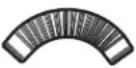
| INSIDE WALLS/CEILING (WALL TO WALL CAP) |  | Elbows (90°/45°) | 10 Ft. X (3) = 30 Ft. | |
 | Turns Less Than 4 Ft. | 2 Ft. X (1) = 2 Ft. | ||
 | Rigid Ducting | 1 Ft. X (5) = 5 Ft. | ||
| WALL CAPS | 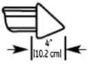 | 4" Wall Cap | 5 Ft. X (1) = | 5 Ft. |
| Total Ductwork Length = TOTAL MUST BE LESS THAN OR EQUAL TO 90 FT. | 46 Ft. | |||
DUCTING COMPONENT EQUIVALENCY CHART
| DUCT PIECES LENGTH X USED = LENGTH | EQUIVALENT RIGID NUMBER EQUIVALENT | |||
| TRANSITION DUCTING (DRYER TO WALL) | 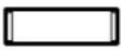 | Rigid Metal 1 Ft. X() = Ducting (Preferred) | Ft. | |
 | Semi-Rigid 25 Ft. Metal Ducting (inside diameter does not change) | X() = Ft. | ||
 | Flexible Metal Ducting (inside diameter changes) | 50 Ft. X() = Ft. | ||
| INSIDE WALLS/CEILING (WALL TO WALL CAP) | 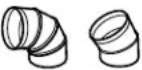 | Elbows (90°/45°) | 10 Ft. X() = Ft. | |
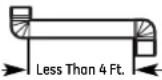 | Turns less Than 4 Ft. | 2 Ft. X() = Ft. | ||
 | Rigid Metal Ducting | 1 Ft. X() = Ft. | ||
 | Semi-Rigid 2 Ft. X() = Ft. Metal Ducting | |||
 | Flexible Metal Ducting Not Recommended | Ft. | ||
| WALL CAPS |  | 4" Wall Cap 5 Ft. X() = Ft. | ||
 | Louvered Wall Cap | 10 Ft. X() = Ft. | ||
 | 2.5" Wall Cap | 23 Ft. X() = | Ft. | |
| Total Ductwork Length = TOTAL MUST BE LESS THAN OR EQUAL TO 90 FT. | Ft. | |||
EXHAUSTING THE DRYER (cont.)
BEFORE YOU BEGIN
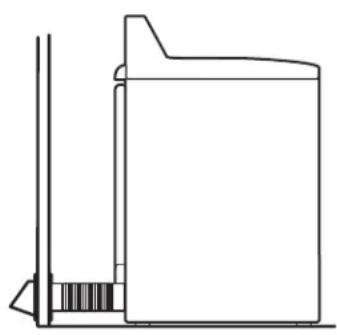
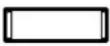
Remove any lint from the wall exhaust opening.

text_image
Internal Duct Opening Wall Check that exhaust hood damper opens and closes freely.STANDARD REAR EXHAUST
We recommend that you install your dryer before installing your washer. This will permit direct access for easier exhaust connection.
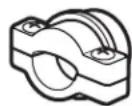
Slide the end of the exhaust duct underneath the clips on the back of the dryer and secure with duct tape or a hose clamp.
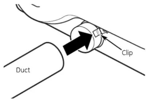
text_image
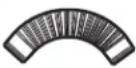
Clip DuctNOTE: We strongly recommend using rigid metal exhaust duct. If using semi-rigid metal duct, cut it to the proper length and avoid bunching of the duct behind the dryer.
- For straight-line installation, connect the dryer exhaust to the wall using duct tape.

text_image
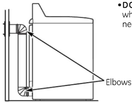
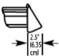
Wall Side Dryer SideRECOMMENDED CONFIGURATION TO MINIMIZE EXHAUST BLOCKAGE
Using duct elbows will prevent duct kinking and collapsing.

text_image
Transition DuctingDRYER EXHAUST TO SIDE OR BOTTOM OF CABINET
If you wish to exhaust your dryer to the side or bottom of the cabinet, order exhaust kit 14-A003, available from your GE supplier.
FINAL SETUP
1 LEVEL THE DRYER
Stand the dryer near the final location. Place a level against the side and bottom of the dryer door frame and use the four leveling legs to level your dryer.
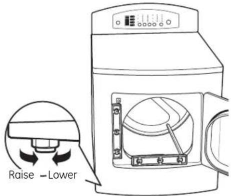
text_image
Raise - Lower2 PLUG IN DRYER

text_image
Ensure proper ground exists before useFINAL SETUP (cont.)
③ DRYER STARTUP
Press the POWER button.
POWER
NOTE: If the dryer has been exposed to temperatures below freezing for an extended period of time, allow it to warm up before pressing POWER. Otherwise, the display will not come on. The dryer is now ready for use.
SERVICING
⚠ WARNING – Label all wires prior to disconnection when servicing controls. Wiring errors can cause improper and dangerous operation after servicing/installation.
For replacement parts and other information, refer to the Owner's Manual for servicing phone numbers.
REVERSING THE DOOR SWING (if desired)
① REMOVE FILLER PLUGS
Open the door and remove the filler plugs opposite the hinges.
natural_image
Technical line drawing of a mechanical component with no visible text or symbols③ REMOVE HANDLE
Remove the screws holding the handle and two spacers.

text_image
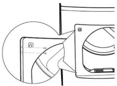
Rear of Door2 REMOVE DOOR
- With the door completely open, remove the BOTTOM screw from each hinge on the dryer face.
- Insert the screws about halfway into the TOP holes, for each hinge, on the opposite side (where you removed the filler plugs). Apply firm pressure to get the screw started in new holes.
natural_image
Diagram of a device interior showing internal components and directional arrows (no text or symbols)- Loosen the TOP screw from each hinge on the dryer face halfway. With one hand holding the top of the door and the other hand holding the bottom, remove the door from the dryer by lifting it UP and OUT.
natural_image
Technical line drawing of a mechanical assembly with no visible text or symbols4 REVERSE DOOR CATCH
Remove the door catch and filler plate. Install them on opposite sides of the door.
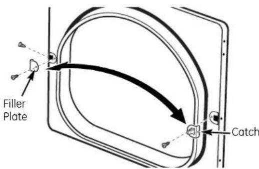
text_image
Filler Plate CatchREVERSING THE DOOR SWING (cont.)
⑤ REVERSE HANDLE
Install the handle on the opposite side of the door.
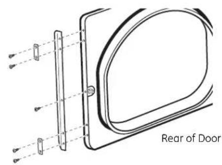
text_image
Rear of Door6 REMOVE HINGES AND REHANG DOOR
Remove the hinges from the door and install them on the opposite side with the hinge pin toward the outside of the door.

natural_image
Diagram of a hinge with two screws, showing alignment between two vertical supports (no text or symbols)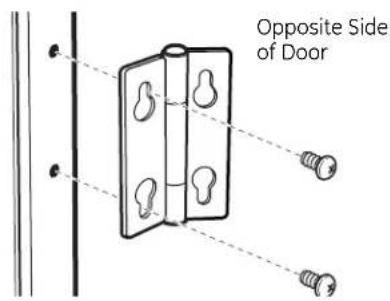
text_image
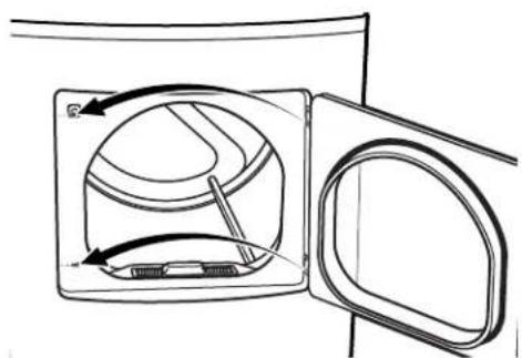
Opposite Side of Door⑥ REMOVE HINGES AND REHANG DOOR (cont.)
Insert the door on the opposite side of the opening by moving the door IN and DOWN until the top hinge and the bottom hinge are resting on the top screws inserted in Step 2.

natural_image
Diagram of a door lock mechanism with a star-shaped component and directional arrow (no text or symbols)Remove the remaining screws from the side of the opening from which the door was removed. With these screws, secure each hinge at the bottom.

natural_image
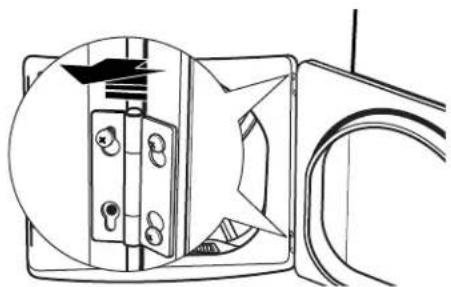
Diagram of a door opening with a curved lid and internal components, showing directional arrows (no text or symbols)Tighten the two top screws of each hinge. Reinsert the plastic plugs on the side from which the door was removed.
natural_image
Technical line drawing of a mechanical component with internal channels and a circular inset view (no text or symbols)
Troubleshooting Tips
Save time and money! Review the chart below first and you may not need to call for service.
| Problem Possible Cause What To Do | ||
| Dryer won't operate | Control panel is asleep | This is normal. Press POWER. |
| Dryer is unpluggedMake sure cord is plugged securely into a working outlet. | ||
| Controls are not set properlyMake sure the cycle was set correctly, close the lid and press START. | ||
| Fuse is blown/circuit breaker is tripped | Check house circuit breakers/fuses. Replace fuses or reset breaker.NOTE:Electric dryers use two fuses or breakers. | |
| Electronics need to be reset | Unplug dryer, wait 2 minutes, plug back in and press POWER. | |
| START was not pressed after a cycle was set | Press START. | |
| Door was opened during the dry cycle | Close the door and reset cycle, to the beginning if necessary. Press START. | |
| Dryer is too cold | If the dryer has been exposed to temperatures below freezing for an extended period of time, allow it to warm up before pressing POWER. Otherwise, the display will not come on. | |
Normal Operating Sounds
The following are normal sounds you may hear:
| Sound | Description |
| Thumping noise when drum rotates | • If the dryer has not been used for an extended period of time, you may hear a thumping noise from temporary flat spots on the drum support rollers. The noise will go away after use. |
GE Dryer Warranty. (For customers in the United States)

All warranty service provided by our Factory Service Centers, or an authorized Customer Care ^® technician. To schedule service, on-line, visit us at ge.com, or call 800.GE.CARES (800.432.2737).
Please have serial number and model number available when calling for service.
Staple your receipt here. Proof of the original purchase date is needed to obtain service under the warranty.
For The Period Of: We Will Replace:
| One YearFrom the date of the original purchase to replace the defective part. | Any part of the dryer which fails due to a defect in materials or workmanship. During this limited one-year warranty, GE will also provide, free of charge, all labor and related service costs |
| Second YearFrom the date of the original purchase | Any part of the dryer which fails due to a defect in materials or workmanship. During this additional one-year limited warranty, you will be responsible for any labor or related service costs. |
| Second through Fifth YearFrom the date of the original purchase | The extra-large or super-capacity dryer drum and main electronic control board if any of these parts should fail due to a defect in materials or workmanship. During this additional three-year limited warranty, you will be responsible for any labor or related service costs. |
What Is Not Covered (in the United States):
■Service trips to your home to teach you how to use the product.
■Improper installation, delivery or maintenance.
■Failure of the product if it is abused, misused or used for other than the intended purpose or used commercially.
■Replacement of the light bulb after its expected useful life.
■Replacement of house fuses or resetting of circuit breakers.
■Damage to the product caused by accident, fire, floods or acts of God.
■Incidental or consequential damage caused by possible defects with this appliance.
■Damage caused after delivery.
■Product not accessible to provide required service.
EXCLUSION OF IMPLIED WARRANTIES—Your sole and exclusive remedy is product repair as provided in this Limited Warranty. Any implied warranties, including the implied warranties of merchantability or fitness for a particular purpose, are limited to one year or the shortest period allowed by law.
This warranty is extended to the original purchaser and any succeeding owner for products purchased for home use within the USA. If the product is located in an area where service by a GE Authorized Servicer is not available, you may be responsible for a trip charge or you may be required to bring the product to an Authorized GE Service location for service. In Alaska, the warranty excludes the cost of shipping or service calls to your home.
Some states do not allow the exclusion or limitation of incidental or consequential damages. This warranty gives you specific legal rights, and you may also have other rights which vary from state to state. To know what your legal rights are, consult your local or state consumer affairs office or your state's Attorney General.
Warrantor: General Electric Company. Louisville, KY 40225
All warranty service provided by our Factory Service Centres or an authorized technician. For service, call 1.800.561.3344.
Please have serial number and model number available when calling for service.
For The Period Of: We Will Replace:
| One YearFrom the date of the original purchase to replace the defective part. | Any part of the dryer which fails due to a defect in materials or workmanship. During this limited one-year warranty, GE will also provide, free of charge, all labor and related service costs |
| Second YearFrom the date of the original purchase | Any part of the dryer which fails due to a defect in materials or workmanship. During this additional one-year limited warranty, you will be responsible for any labor or related service costs. |
| Second through Fifth YearFrom the date of the original purchase | The extra-large or super-capacity dryer drum and main electronic control board if any of these parts should fail due to a defect in materials or workmanship. During this additional three-year limited warranty, you will be responsible for any labor or related service costs. |
What Is Not Covered (in Canada):
■Service trips to your home to teach you how to use the product.
■Improper installation, delivery or maintenance.
■Failure of the product if it is abused, misused or used for other than the intended purpose or used commercially.
■Replacement of the light bulb after its expected useful life.
■Replacement of house fuses or resetting of circuit breakers.
■Damage to the product caused by accident, fire, floods or acts of God.
■Incidental or consequential damage caused by possible defects with this appliance.
■Damage caused after delivery.
■Product not accessible to provide required service.
EXCLUSION OF IMPLIED WARRANTIES—Your sole and exclusive remedy is product repair as provided in this Limited Warranty. Any implied warranties, including the implied warranties of merchantability or fitness for a particular purpose, are limited to one year or the shortest period allowed by law.
This warranty is extended to the original purchaser and any succeeding owner for products purchased for home use within Canada. In-home warranty service will be provided in areas where it is available and deemed reasonable by Mabe to provide.
WARRANTOR IS NOT RESPONSIBLE FOR CONSEQUENTIAL DAMAGES.
Warrantor: MABE CANADA INC.

GE Appliances Website
In the U.S.: ge.com
Have a question or need assistance with your appliance? Try the GE Appliances Website 24 hours a day, any day of the year! For greater convenience and faster service, you can now download Owner's Manuals, order parts or even schedule service on-line. In Canada: www.geappliances.ca
Schedule Service
In the U.S.: ge.com
Expert GE repair service is only one step away from your door. Get on-line and schedule your service at your convenience any day of the year! Or call 800.GE.CARES (800.432.2737) during normal business hours.
In Canada, call 1.800.561.3344
Real Life Design Studio
In the U.S.: ge.com
GE supports the Universal Design concept—products, services and environments that can be used by people of all ages, sizes and capabilities. We recognize the need to design for a wide range of physical and mental abilities and impairments. For details of GE's Universal Design applications, including kitchen design ideas for people with disabilities, check out our Website today. For the hearing impaired, please call 800.TDD.GEAC (800.833.4322).
In Canada, contact: Manager, Consumer Relations, Mabe Canada Inc.
Suite 310, 1 Factory Lane
Moncton, N.B. E1C 9M3

Extended Warranties
In the U.S.: ge.com
Purchase a GE extended warranty and learn about special discounts that are available while your warranty is still in effect. You can purchase it on-line anytime, or call 800.626.2224 during normal business hours. GE Consumer Home Services will still be there after your warranty expires. In Canada, call 1.888.261.2133

Parts and Accessories
In the U.S.: ge.com
Individuals qualified to service their own appliances can have parts or accessories sent directly to their homes (VISA, MasterCard and Discover cards are accepted). Order on-line today, 24 hours every day or by phone at 800.626.2002 during normal business hours.
Instructions contained in this manual cover procedures to be performed by any user. Other servicing generally should be referred to qualified service personnel. Caution must be exercised, since improper servicing may cause unsafe operation.
Customers in Canada should consult the yellow pages for the nearest Mabe service center, or call 1.800.661.1616.

Contact Us In the U.S.: ge.com
If you are not satisfied with the service you receive from GE, contact us on our Website with all the details including your phone number, or write to: General Manager, Customer Relations
GE Appliances, Appliance Park
Louisville, KY 40225
In Canada: www.geappliances.ca, or write to: Director, Consumer Relations, Mabe Canada Inc.
Suite 310, 1 Factory Lane
Moncton, N.B. E1C 9M3

Register Your Appliance
In the U.S.: ge.com
Register your new appliance on-line—at your convenience! Timely product registration will allow for enhanced communication and prompt service under the terms of your warranty, should the need arise. You may also mail in the pre-printed registration card included in the packing material. In Canada: www.geappliances.ca
Sécheuses Profile
1 Power (alimentation)
natural_image
Technical line drawing of a mechanical component with internal grid structure (no text or symbols)natural_image
Line drawing of a microwave oven with a lid and ruler inside (no text or symbols)natural_image
Simple line drawing of a kitchen appliance with directional arrows indicating motion (no text or symbols)PLACEMENT DE VOTRE SÉCHEUSE
natural_image
Illustration of a flexible hose with threaded ends and hexagonal connectors (no text or symbols)natural_image
Hand placing a button into an electrical control box with multiple buttons (no text or symbols visible)natural_image
Simple line drawing of a trash bin with a downward arrow and trash tube (no text or symbols)RACCORDEMENT D'UNE SÉCHEUSE À GAZ (suite)
EXIGENCES RELATIVES AU GAZ
▲ AVERTISSEMENT
natural_image
Diagram of a flexible hose connecting a pipe with a curved cable (no text or symbols)natural_image
Illustration of hands using a tool to lift a pipe, no text or symbols presentRACCORDEMENT DE LA SÉCHEUSE À L'ALIMENTATION EN GAZ (suite)
natural_image
Illustration of hands connecting a mechanical pipe to a valve (no text or symbols present)natural_image
Pure electrical circuit lines without any symbolsnatural_image
Hand placing a component into an electrical outlet box (no text or symbols visible)RENSEIGNEMENTS SUR LES RACCORDS ÉLECTRIQUES POUR SÉCHEUSES ÉLECTRIQUES
natural_image
Line drawing of a hand inserting a component into a device (no text or symbols)BRANCHEMENT DU CORDON D'ALIMENTATION DE LA SÉCHEUSE (suite)
natural_image
Technical line drawing of a mechanical device with no visible text or symbols•COUPEZ
natural_image
Pure geometric diagram with intersecting lines and a diagonal line, no text or symbols present• N'ÉCRASEZ PAS
natural_image
Diagram of a battery with a hose and no visible text or symbols•N'UTILISEZ PAS
natural_image
Simple line drawing of a mechanical component with a diagonal line and arrow indicating direction (no text or symbols)•NE PRESSEZ PAS
natural_image
Pure mechanical diagram showing a diagonal line without any text, numbers, or symbols•N'INSTALLEZ PAS
natural_image
Technical line drawing of a mechanical component with no visible text or symbols③ ENLEVEZ LA POIGNÉE
natural_image
Diagram of a device interior showing internal components and directional arrows (no text or symbols)natural_image
Technical line drawing of a mechanical component with no visible text or symbols4 INVERSEZ LE LOQUET DE LA PORTE
natural_image
Diagram of a hinge with two screws inserted, showing alignment lines (no text or symbols)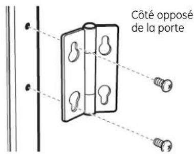
natural_image
Pure technical diagram of a mechanical device with no visible text, numbers, or symbolsnatural_image
Diagram of a door opening with a lid and internal components, showing directional arrows indicating movement (no text or symbols)natural_image
Technical line drawing of a mechanical component with internal channels and a circular inset view (no text or symbols)