
9077SF - Angle Grinder MAKITA - Free user manual and instructions
Find the device manual for free 9077SF MAKITA in PDF.


| Product Type | Angle Grinder |
| Brand | Makita |
| Model | 9077SF |
| Power Source | 120V AC, 7.5 Amps |
| No-Load Speed | 11,000 RPM |
| Wheel Diameter | 4-1/2" (115 mm) |
| Spindle Thread | 5/8"-11 UNC |
| Weight | 4.5 lbs (2.04 kg) |
| Overall Length | 10-1/2" (267 mm) |
| Switch Type | Paddle switch with lock-off button |
| Side Handle | Reversible (Left/Right) |
| Spindle Lock | Yes |
| Protection Guard | Adjustable wheel guard |
| Brushes | Shoe-type, externally accessible |
| Housing | Aluminum gear housing |
| Maintenance | Regular brush inspection and gear grease replacement |
| Safety Compliance | UL listed, OSHA compliant with guard |
| Repairability | Spare parts available via Makita service centers |
Frequently Asked Questions - 9077SF MAKITA
User questions about 9077SF MAKITA
0 question about this device. Answer the ones you know or ask your own.
Ask a new question about this device
Download the instructions for your Angle Grinder in PDF format for free! Find your manual 9077SF - MAKITA and take your electronic device back in hand. On this page are published all the documents necessary for the use of your device. 9077SF by MAKITA.
USER MANUAL 9077SF MAKITA
natural_image
Line drawing of a power tool with a circular base and multiple blades (no text or symbols)

1
2
3

4

5
6

7

8
9

10
Symbols
The following show the symbols used for the tool. Be sure that you understand their meaning before use
Symboles
Explanation of general view
⑨ Depressed center wheel
⑩ Inner flange
⑪ Lock nut wrench
⑫ Tighten
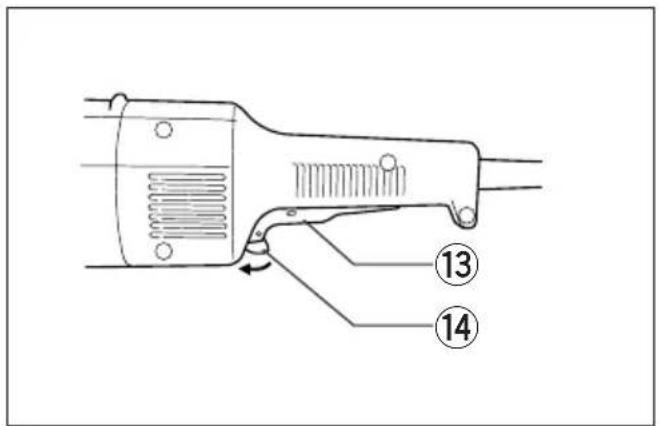
⑬ Switch trigger
⑭ Lock lever
⑮ △ mark
⑯ Motor housing
⑰ Lock button
⑱ Handle
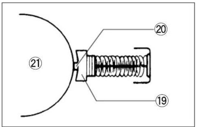
⑲ Carbon brush
⑳ Insulating tip
②1 Commutator
② Brush holder cap
②3 Screwdriver
SPECIFICATIONS
Model 9077/9077S 9077SL 9079/9079S
Depressed center wheel diameter 180 mm 180 mm 230 mm
Spindle thread M14 M14 M14
No load speed (mir) 7,600 6,000 6,000
Overall length 484 mm 484 mm 484 mm
Net weight 5.3 kg 5.3 kg 5.3 kg
- Due to our continuing program of research and development, the specifications herein are subject to change without notice.
• Note: Specifications may differ from country to country.
Power supply
The tool should be connected only to a power supply of the same voltage as indicated on the nameplate, and can only be operated on single-phase AC supply. 8. They are double-insulated in accordance with European Standard and can, therefore, also be used from sockets without earth wire.
For public low-voltage distribution systems of between 220 V and 250 V
Switching operations of electric apparatus cause voltage fluctuations. The operation of this device under unfavorable mains conditions can have adverse effects to the operation of other equipment. With a mains impedance equal or less than 0.25 Ohms it can be presumed that there will be no negative effects. The mains socket used for this device must be protected with a fuse or protective circuit breaker having slow tripping characteristics.
Safety hints
For your own safety, please refer to the enclosed safety instructions.
ADDITIONAL SAFETY RULES
ENB031-3
- Always wear safety goggles and ear protectors during operation.
- Always be sure that the tool is switched off and unplugged before carrying out any work on the tool.
- Keep guards in place.
-
Use only wheels with correct size and wheels having a maximum operating speed at least as 2 high as the highest No Load Speed marked on the tool's nameplate.When using depressed center wheels, be sure to use only fiberglass2 reinforced wheels.
-
Check the wheel carefully for cracks or damage before operation. Replace cracked or damaged wheel immediately.
- Observe the instructions of the manufacturer for correct mounting and use of wheels. Handle and store wheels with care.
- Do not use separate reducing bushings or adaptors to adapt large hole abrasive wheels.
- Use only flanges specified for this tool.
- Do not damage the spindle, the flange (especially the installing surface) or the lock nut. Damage to these parts could result in wheel breakage.
- For tools intended to be fitted with threaded hole wheel, ensure that the thread in the wheel is long enough to accept the spindle length.
- Before using the tool on an actual workpiece, test run the tool at the highest no load speed for at least 30 seconds in a safe position. Stop immediately if there is any vibration or wobbling that could indicate poor installation or a poorly balanced wheel. Check the tool to determine the cause.
- Check that the workpiece is properly supported.
- Hold the tool firmly.
- Keep hands away from rotating parts.
- Make sure the wheel is not contacting the workpiece before the switch is turned on.
- Use the specified surface of the wheel to perform the grinding.
- Do not use cutting off wheel for side grinding.
- Watch out for flying sparks. Hold the tool so that sparks fly away from you and other persons or flammable materials.
- Pay attention that the wheel continues to s rotate after the tool is switched off.
-
Do not touch the workpiece immediately after an operation; it may be extremely hot and could burn your skin.
Position the tool so that the power cord always stays behind the tool during operation. -
If working place is extremely hot and humid, switch action (Fig. 6)
badly polluted by conductive dust, use a short-circuit breaker (30 mA) to assure operator safety.
- Do not use the tool on any materials containing asbestos.
- Do not use water or grinding lubricant.
SAVE THESE INSTRUCTIONS.
OPERATING INSTRUCTIONS
Installing wheel guard (Fig. 1)
Important:
Always be sure that the tool is switched off and unplugged before installing or removing the wheel guard.
When installing a depressed center wheel or an abrasive cut-off wheel, always use a wheel guard. Loosen the lever on the wheel guard. Mount the wheel guard with the protrusion on the wheel guard band aligned with the notch on the bearing box. T rotate the wheel guard 180 degrees clockwise.
Tighten the lever to fasten the wheel guard. If the lever is too tight or too loose to fasten the wheel guard, loosen or tighten the screw to adjust the tightening of the wheel guard band.
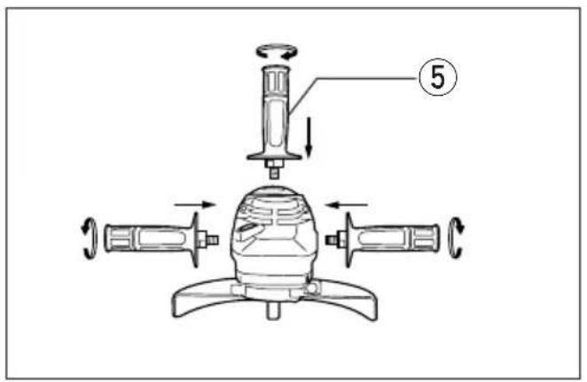
Installing side grip (auxiliary handle) (Fig. 2)
Important:
Always be sure that the tool is switched off and unplugged before installing or removing the side grip
Always install the side grip on the tool securely be operation. The side grip can be installed in any of three positions on the sides of the tool, whichever convenient and keeps the guard properly positioned
Always hold the tool's switch handle and the side firmly with both hands during operation.
Shaft lock (Fig. 3)
Press the shaft lock to prevent spindle rotation when installing or removing accessories.
CAUTION:
Never actuate the shaft lock when the spindle is moving. The tool may be damaged.
Installing or removing depressed center wheel (Fig. 4 & 5)
Important:
Always be sure that the tool is switched off and unplugged before installing or removing the wheel.
Mount the inner flange onto the spindle. Fit the wh on over the inner flange and screw the lock nut of the spindle.
To tighten the lock nut, press the shaft lock firmly that the spindle cannot revolve, then use the lock wrench and securely tighten clockwise.
To remove the wheel, follow the installation procedure in reverse.
CAUTION:
"Before plugging in the tool, always check to see that the switch trigger actuates properly and returns to the "OFF" position when released.
For U.K., Australia, New Zealand, France, Réunion and Algeria
To prevent the trigger from being accidentally actuated, a lock lever is provided. To start the tool, push the lock lever in the arrow direction and then pull the trigger. Release the trigger to stop.
For Germany, Austria, Italy, Switzerland, Netherlands, Belgium, Spain, Portugal, Denmark, Sweden, Norway, Finland, Greece, Russia and South Africa
To prevent the trigger from being accidentally actuated, a lock lever is provided. To start the tool, push the lock lever in the arrow direction and then pull the trigger. Release the trigger to stop. For continuous operation, push the lock lever in the arrow direction, pull the trigger and then push the lock lever further in the arrow direction. To stop the tool from the locked position, pull the trigger fully, then release it.
For all other countries
To start the tool, simply pull the trigger. Release the trigger to stop. For continuous operation, pull the trigger and then push the lock lever in the arrow direction. To stop the tool from the locked position, pull the trigger fully, then release it.
NOTE:
Models 9077S, 9077SL and 9079S begin to run slowly when they are turned on. This soft start feature assures smoother operation and less operator fatigue.
'Switch handle mounting positions (Fig. 7)
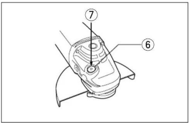
The switch handle can be rotated to either 90° left or right to fit your work needs. First, unplug the tool. Press the lock button and rotate the switch handle until the △ mark on the lock button is aligned with that on the motor housing. The switch handle will be locked in that position.
Operation (Fig. 8)
CAUTION:
After operation, always switch off the tool and wait until the wheel has come to a complete stop before putting the tool down.
Hold the tool firmly with both hands. Turn the tool on and then apply the wheel or disc to the workpiece. In general, keep the edge of the wheel or disc at an angle of about 15^ - 30^ to the workpiece surface.
During the break-in period with a new wheel, do not work the tool in the B direction or it will cut into the so workpiece. Once the edge of the wheel has been rounded off by use, the wheel may be worked in both A and B directions.
WARNING:
- It should never be necessary to force the tool. The weight of the tool applies adequate pressure. Forcing and excessive pressure could cause dangerous wheel breakage.
- Continued use of a worn-out wheel may result in wheel explosion and serious personal injury. Depressed center wheel should not be used after it has been worn down to 115mm in diameter. Use of the wheel after this point is unsafe and it should be removed from service and rendered unusable by intentional destruction.
MAINTENANCE
CAUTION:
Always be sure that the tool is switched off and unplugged before carrying out any work on the tool.
Replacement of carbon brushes (Fig. 9 & 10)
When the resin insulating tip inside the carbon brush is exposed to contact the commutator, it will automatically shut off the motor. When this occurs, both carbon brushes should be replaced at the same time. Use only identical carbon brushes.
To maintain product safety and reliability, repairs, maintenance or adjustment should be carried out by a Makita Authorized Service Center.
NEDERLANDS
Model 9077/9077S 9077SL 9079/9079S
These accessories or attachments are recommended for use with your Makita tool specified in this manual use of any other accessories or attachments might present a risk of injury to persons. The accessories of attachments should be used only in the proper and intended manner.
F ACCESSOIRES
ATTENTION :
EC-DECLARATION OF CONFORMITY
The undersigned, Yasuhiko Kanzaki, authorized by Makita Corporation, 3-11-8 Sumiyoshi-Cho, Anjo, Aichi 446-8502 | Japan declares that this product
(Serial No.: series production)
manufactured by Makita Corporation in Japan is in compliance with the following standards or standardized documents,
HD400, EN50144, EN55014, EN61000
in accordance with Council Directives, 73/23/EEC, 89/336/EEC and 98/37/EC.
ITALIANO
DÉCLARATION DE CONFORMITÉ CE
HD400, EN50144, EN55014, EN61000.
ESPAÑOL
Michigan Drive, Tongwell, Milton Keynes,
Bucks MK15 8JD, ENGLAND
PORTUGUÊS
EU-DEKLARATION OM KONFORMITET
Undertegnede, Yasuhiko Kanzaki, med fuldmagt fra Maki Corporation, 3-11-8 Sumiyoshi-Cho, Anjo, Aichi 446-8502 Japan, erklærer hermed, at dette produkt (Løbenummer: serieproduktion)
Michigan Drive, Tongwell, Milton Keynes,
Bucks MK15 8JD, ENGLAND
ENGLISH
Noise And Vibration Of Model 9077/9077S/9079/9079S
The typical A-weighted noise levels are
sound pressure level: 88 dB (A)
sound power level: 101 dB (A)
Wear ear protection.
3.1.1. The following table is presented in the following table:
DANSK


- Symbols
- Symboles
- Explanation of general view
- SPECIFICATIONS
- Model 9077/9077S 9077SL 9079/9079S
- Power supply
- For public low-voltage distribution systems of between 220 V and 250 V
- Safety hints
- ADDITIONAL SAFETY RULES
- SAVE THESE INSTRUCTIONS.
- OPERATING INSTRUCTIONS
- Installing wheel guard (Fig. 1)
- Installing side grip (auxiliary handle) (Fig. 2)
- Shaft lock (Fig. 3)
- Installing or removing depressed center wheel (Fig. 4 & 5)
- For U.K., Australia, New Zealand, France, Réunion and Algeria
- For Germany, Austria, Italy, Switzerland, Netherlands, Belgium, Spain, Portugal, Denmark, Sweden, Norway, Finland, Greece, Russia and South Africa
- For all other countries
- 'Switch handle mounting positions (Fig. 7)
- Operation (Fig. 8)
- WARNING:
- MAINTENANCE
- CAUTION:
- NEDERLANDS
- F ACCESSOIRES
- ATTENTION :
- EC-DECLARATION OF CONFORMITY
- ITALIANO
- DÉCLARATION DE CONFORMITÉ CE
- ESPAÑOL
- PORTUGUÊS
- EU-DEKLARATION OM KONFORMITET
- ENGLISH
- Noise And Vibration Of Model 9077/9077S/9079/9079S
- DANSK
Brand : MAKITA
Model : 9077SF
Category : Angle Grinder