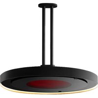
Eclipse Smart-Heat BH0920001 - Heating Bromic - Free user manual and instructions
Find the device manual for free Eclipse Smart-Heat BH0920001 Bromic in PDF.


| Product Type | Outdoor Patio Heater |
| Model | Eclipse Smart-Heat BH0920001 |
| Brand | Bromic |
| Heat Source | Electric |
| Heat Output | 5000 BTU/h (approx. 1500 W) |
| Coverage Area | Up to 100 sq ft (9.3 m²) |
| Mounting Type | Ceiling or wall mount (bracket included) |
| Dimensions (W x H x D) | 32 x 10 x 6 in (81.3 x 25.4 x 15.2 cm) |
| Weight | 12.5 lb (5.7 kg) |
| Power Supply | 120 V, 60 Hz, 12.5 A |
| Control Type | Smart-Heat (remote control and app compatible) |
| Heating Elements | Infrared quartz tube |
| Safety Features | Overheat protection, tip-over shut-off, IP65 rated |
| Material | Stainless steel and aluminum |
| Warranty | 1 year limited warranty |
| Certifications | ETL, FCC, cETLus |
| Installation | Hardwired (professional installation recommended) |
| Compatible With | Smart home systems (Amazon Alexa, Google Assistant) |
| Maintenance | Wipe with damp cloth; clean reflector periodically |
| Spare Parts | Replacement heating element, remote control, mounting bracket |
Frequently Asked Questions - Eclipse Smart-Heat BH0920001 Bromic
User questions about Eclipse Smart-Heat BH0920001 Bromic
0 question about this device. Answer the ones you know or ask your own.
Ask a new question about this device
Download the instructions for your Heating in PDF format for free! Find your manual Eclipse Smart-Heat BH0920001 - Bromic and take your electronic device back in hand. On this page are published all the documents necessary for the use of your device. Eclipse Smart-Heat BH0920001 by Bromic.
USER MANUAL Eclipse Smart-Heat BH0920001 Bromic
| PROP. 65 WARNING FOR CALIFORNI A RESIDENTS |
| Cancer and Reproductive Harm - www.P65Warnings.ca.gov |
| AVERTISSEMENT PROP. 65 POUR LES RESIDENTS DE LA CALIFORNIE |
| Cancer et Troubles de l'appareil reproducteur - www.P65Warnings.ca.gov |
| AVERTISSEMENT PROP. 65 PARA LOS RESIDENTES DE CALIFORNIA |
| Cancer y Daño Reproductivo - www.P65Warnings.ca.gov |
ECLIPSE SMART-HEAT™ ELECTRIC
BY BROMIC
INSTRUCTION MANUAL

natural_image
Modern black and gold pendant light fixture with a circular base and vertical pole (no text or symbols)This manual contains important information about the installation, operation, and maintenance of Eclipse Smart-Heat™ Electric Heaters. Please pay close attention to the important safety information shown throughout this instruction manual. Any safety information will be accompanied by the following safety alert symbols

DANGER, ⚠WARNING, ⚠IMPORTANT
When using electrical appliances, basic precautions should always be followed to reduce the risk of fire, electrical shock, and injury to persons, including the following:
- READ THIS MANUAL CAREFULLY - Read all instructions before installing, servicing or using this heater.
- For the ceiling/ wall mounted heater, installation must comply with NEC and CEC code and local building code.
- This heater is hot when in use. To avoid burns, do not let bare skin touch the hot surfaces.
- Keep combustible materials such as furniture, pillows, bedding, papers, clothes and curtains at least 3.3 feet from the heater head in all directions.
- Improper installation, operation, or maintenance can result in death, severe injury, or property damage.
- Extreme caution is necessary when any heater is used by or near children or people who are infirmed and whenever the heater is left operating and unattended.
- Do not operate any heater after it malfunctions. Disconnect power at service panel and have heater inspected by a licensed electrical contractor before reusing.
- To disconnect heater, turn controls to off, and turn off power to heater circuit at main disconnection panel.
- Do not insert or allow foreign objects to enter any ventilation or exhaust opening as this may cause an electric shock or fire or damage the heater.
- To prevent a possible fire, do not block air intakes or exhaust in any manner.
- A heater has hot parts inside. Do not use it in the areas where gasoline, paint or flammable liquids are used or stored.
- Use this heater only as described in this manual. Any other use not recommended by the manufacturer may cause fire, electric shock or injury to persons.
• This appliance is intended for installation with 220-240 Volt Power supply - Installation MUST be carried out by a licensed and authorised technician in accordance with local electrical codes.
- This product is intended for domestic and commercial use.
• International Registered Designs pending - SAVE THESE INSTRUCTIONS
Correct disposal of this product

natural_image
Symbol of a trash bin with crossed lines indicating no waste or restriction, and a solid black rectangle below (no text or labels)This marking indicates that this product should not be disposed with other household wastes throughout the EU. To prevent possible harm to the environment or human health from uncontrolled waste disposal, recycle it responsibly to promote the sustainable reuse of material resources. To return your used device, please use the return and collection systems or contact the retailer from whom the product was purchased so that they may organise environmentally safe recycling.
BROMIC®
HEATING
Head Office: 10 Phiney Place, Ingleburn, NSW 2565 Australia
Telephone: 1300 276 642 (within Australia) or +61 2 9748 3900 (from overseas) Fax: +61 2 9748 4289
Email: info@bromic.com Web: www.bromic.com
Note: Bromic Pty Ltd reserves the right to make changes to specifications, parts, components and equipment without prior notification. This installation, operation and service manual may not be reproduced in any form without prior written consent from Bromic Pty Ltd.
CONTENT
IMPORTANT NOTES & WARNINGS 4-5
PRODUCT OVERVIEW 6
PRODUCT DESCRIPTION 6
SPECIFICATIONS 6
PRODUCT FEATURES 6
KEY DIMENSIONS & CLEARANCES 7
INSTALLATION INSTRUCTIONS - CEILING MOUNTED HEATER 8-14
BOX CONTENTS 8-9
WARNING 9
INSTRUCTIONS FOR SINGLE POLE OPTIONS 10-11
INSTRUCTIONS FOR TWIN POLE OPTION 12-14
INSTALLATION INSTRUCTIONS - WALL MOUNTED HEATER 15-22
BOX CONTENTS 15-16
WARNING 17
INSTRUCTIONS FOR WALL MOUNTED OPTION 18-22
ELECTRICAL INSTALLATION - PENDANT HEATER CONTROLS 23-25
PENDANT HEATER CONTROL WIRING DIAGRAM 26-27
FOR INSTALLATION USING BROMIC ECLIPSE PENDANT CONTROL 26
FOR INSTALLATION NOT USING BROMIC ECLIPSE PENDANT CONTROL 27
OPERATION INSTRUCTIONS 28-30
REMOTE CONTROL FUNCTIONS 28
TURNING THE APPLIANCE ON 28
TURNING THE APPLIANCE OFF 28
REMOTE CONTROL BATTERY 29
PAIRING REMOTE CONTROL TO HEATER PCB 29
PAIRING REMOTE CONTROL TO LED PCB 30
MAINTENANCE & SERVICING 31
TROUBLESHOOTING 32
REPLACEMENT PARTS 32
IMPORTANT NOTES & WARNINGS

WARNING
- IMPORTANT - Installation MUST be carried out by a licensed electrical contractor.
• Heater must be installed by 2 persons. - Improper installation, adjustment, or alteration and failure to follow the warnings and instructions in this manual could result in severe personal injury, death or property damage.
- The manufacturer is not responsible for any damage resulting from improper use. The manufacturer emphasises that this appliance should be used in a responsible manner and that all procedures, warnings, and safety instructions contained in this booklet should be followed strictly.
- The installer is to ensure that the requirements of the local authority, local electrical installation code, municipal building codes, and any other relevant statutory regulations are carried out.
- Do not use or store flammable materials near this appliance.
- This installation, operation and service manual should not be removed from the site of installation. Installer should leave manual with the customer for future reference.
- A minimum safety distance of 3.3 feet should always be left in front of the Heater Head.
- The Heater head must be installed at least 8.0 feet above the floor.
- The Heater must not be located immediately below or in front of an electrical socket outlet. Heat radiated from the appliance may damage the electricity outlet or plug if placed incorrectly.
- Any guard or other protective device removed for servicing (conducted by a licensed electrical contractor) must be fitted in place before operating the heater.
- This appliance can be used by children aged from 12 years and above and persons with reduced physical, sensory or mental capabilities or lack of experience and knowledge if they are supervised.
• Children shall not play with the appliance. - Cleaning and user maintenance shall not be made by children without supervision.
• Children of less than 12 years should be kept away unless continuously supervised. - Some parts of this product can become very hot and cause burns. Particular attention has to be given where children and vulnerable people are present.
- Keep packaging materials out of reach of children.
- Do not spray aerosols or flammable materials in the vicinity of this appliance while it is in operation or whilst heater surface is hot.
-
Installation and repair must be carried out by a qualified and licensed electrical contractor only. The heater should be inspected before use and at least annually serviced and inspected by a qualified and licenced service technician.
-
The Heater Head has no serviceable parts. For the Poles, please refer to the Maintenance and Servicing section for more details regarding troubleshooting and replacement parts.
- The LED contained in this luminaire is non-replaceable and must not be removed.
- Do not perform maintenance until heater has been turned off, power disconnected, and heater temperature has cooled to room temperature.
- Certain materials or items, when stored under or near the appliance, will be subjected to radiant heat and could be discoloured or seriously damaged. Combustible materials e.g. floors, furniture, fixtures and plants must be kept a minimum of 3.3 feet from the front of the heater head.
- Be sure the heater is not facing the ceiling or flammable or combustible substances/ materials.
- This radiant heater is NOT intended to be installed on or in vehicles and/or boats.
- Do not attempt to alter the unit in any manner.
- Remove all transit protection & packaging before use.
- Do not paint any surface of the heater.
- Care must be taken during installation. After removing packaging, glass must be inspected for damage before use. If damage to the appliance is suspected, discontinue use immediately and contact the supplier.
- Check for damage to the appliance before each use. The heater must not be used if the glass panel or any other part of the heater is damaged. If damage to the appliance is suspected, discontinue use immediately and contact the supplier.
- Care must be taken around the appliance to ensure it is not damaged. Ball games that could accidentally hit the heater must not be played around the appliance.
• After unpacking, make sure the appliance shows no signs of visible damage or tampering. If the appliance appears damaged, contact the place of purchase for assistance. - This appliance must only be used on a 220-240V AC single-phase power supply.
- Do not touch the heating surface at any time, even when the heater is turned off and has cooled down.
- Do not touch the heater with wet hands at any time.
- At the end of this product's useful life, it must not be disposed of as domestic waste, but must be taken to a collection centre for waste electrical and electronic equipment. It is the user's responsibility to dispose of this appliance through the appropriate channels at the end of its useful life. Failure to do so may incur the penalties established by local laws governing waste disposal. Proper differential collection, and the subsequent recycling, processing and environmentally compatible disposal of waste equipment avoids unnecessary damage to the environment and possible related health risks, and also promotes recycling of the materials used in the appliance. For further information on waste collection and disposal; contact your local waste disposal service or the place of purchase.
IMPORTANT NOTES AND WARNINGS CONTINUED ...
- In case of direct connection to a supply line, a bipolar circuit breaker with contact opening distance of at least 1/8 inch must be fitted upstream from the supply line. Contact an authorised service technician if you are unsure if you have a circuit breaker installed on the premises.
- Do not install the heater directly near a bathtub, shower, swimming pool or other body of water. Any switches or controls must not be within reach of a person in the bathtub, shower, swimming pool or other body of water.
- To maintain Ingress Protection Rating (IP54), only suitable IP54 (or better) rated outdoor plug & sockets should be used for electrical installation.
- This product does not have a switch for electrical disconnection. A means for disconnection of the heater must be incorporated in the wall socket & fixed wiring according to the local electrical codes.
- If the supply cable is damaged, it must be replaced by the manufacturer, its service agent or similarly qualified persons in order to avoid a safety hazard.
- This heater is not equipped with a device to control the room temperature. Do not use this heater in small rooms when they are occupied by persons not capable of leaving the room on their own, unless constant supervision is provided.
- Do not excessively bend the electrical connection to the power supply.
-
Keep the electrical cable away from sharp edges during handling and installation.
-
Do not pull on the electrical cable or subject it to traction force.
- Caution should be taken when dismantling goods from shipping container to prevent from injury when lifting heavy parts. Maximum safe lifting 35 lbs per person.
- Do not install heater to an unsecured structure. Mounting surface integrity shall be determined suitable by the installer based on weight & type of mounting option chosen.
- Do not lean on heater or rest any objects leaning up against heater, including the arm.
- Do not hang any foreign items off any part of this appliance e.g. do not hang towels, clothing, lines, lights, cables.
• Do not swing from arm or heater head. - Do not stand or sit on any part of heater, including the base.
- Do not use heater if Heater Head is not level with the ground. Angle must be checked during assembly using spirit level (not included).
• Do not use heater if heater head or pole is loose. - Check product label for correct voltage and wattage to ensure power source conforms to the heater's requirements.
- The exterior housing of the heater should be cleaned regularly. To clean the appliance; ensure heater is off and has been off for at least 2 hours after operation, before wiping off any dirt/dust with a soft damp cloth & glass cleaner. Salt in the air can cause rusting of metal, especially at locations near the coast. Additional cleaning of the heater with a soft damp cloth fortnightly will aid in maintaining the product's appearance.
- Do not clean heater with cleaners that are combustible or corrosive.
SAVE THESE INSTRUCTIONS
PRODUCT DESCRIPTION
The Eclipse Smart-Heat ^™ Electric is designed to provide efficient space heating for commercial and residential applications.
The Eclipse Smart-Heat ^™ Electric heaters have electrical approval in Australia, New Zealand, USA, Canada, Europe, UK, and are rated to IP54 for Ingress Protection, making the Eclipse Smart-Heat ^™ Electric Portable the perfect solution for a variety of indoor and outdoor heating applications.
PRODUCT SPECIFICATIONS
| SPECIFICATIONS | |
| Model Eclipse Smart-Heat | ^TM Electric |
| Part No (Heater Eclipse Pendant USA/CAN) BH0920001-1 | |
| Part No (Straight Ceiling Mount Pole 8") BH3230001 | |
| Part No (Straight Ceiling Mount Pole 24") BH3230002 | |
| Part No (Twin Straight Ceiling Mount Pole 24") BH3230003 | |
| Part No (Curved Ceiling Mount Pole 24") BH3230004 | |
| Part No (Straight Ceiling Mount Pole 48") BH3230005 | |
| Part No (Wall Mount Pole) BH3230006 | |
| Part No (Eclipse Pendant Control USA/CAN) BH3230007-1 | |
| Appliance Output (watts) 2900 W | |
| Light Output (watts) 13 W @ 24 V DC | |
| Power Connection Required (Volts) 220-240 V - a.c. - 60 Hz | |
| Ingress Protection IP54 | |
| Heater Head Dimensions (W x H x D) | 27.6 x 27.6 x 4.4 in |
| Heater Head Weight | 30 lbs |
| Finish | Matt Black |
| Approval | Electrical: SGS - 801126 (US/CAN)Radio: FCC ID: P59TVEVO916S (US),Radio: IC: 11242A-TVEVO916S (CAN),EMC: SGS - GZEM201101691501 (US), GZEM201101691601 (CAN) |
PRODUCT FEATURES
■ Stylish, slimline and contemporary design to suit any decor.
- Efficient directional space heating with 3 built in heat levels.
■ Heaters can also be integrated into smart control systems
■ Wind resistant & IP54 water protection rating
- Suitable for outdoor and indoor heating applications such as restaurants, cafes, bars and clubs, factories, office spaces, designated smoking areas, public areas, hotels, homes and more.
Heaters must be installed according to the minimum installation clearances shown in these diagrams.
The stated clearance to combustible materials represents surface temperature of 117^ F above room temperature. Building material with a low heat tolerance (such as plastic, vinyl siding, canvas, tri-ply etc.) may subject to degradation at lower temperature. It is the installer's responsibility to assure that adjacent materials are protected.
Contents Packed in (3) Boxes
Box 1 Contents
| Eclipse Head AssemblyIncluding pre-assembled 2 x DomeHead Screws (M4 - Length: 6mm) | 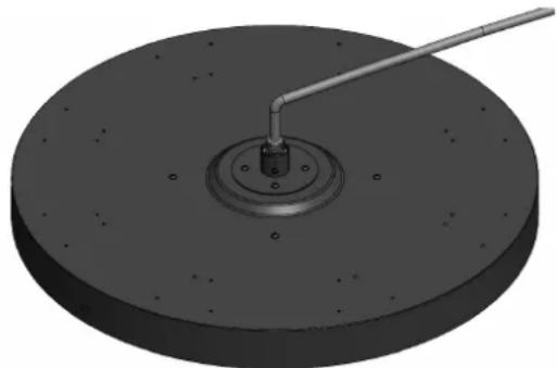 |
| Instruction Manual(This Document) | 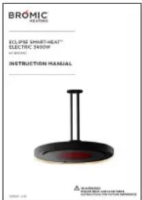 |
Box 2 Contents
| Pendant Pole Assemblyone of the following styles:• Twin Straight Ceiling Mount Pole 24”• Curved Ceiling Mount Pole 24”• Straight Ceiling Mount Pole 8”• Straight Ceiling Mount Pole 24”• Straight Ceiling Mount Pole 48” |  |
| 6 x Dome Head Screws(M4 - Length: 6mm) |  |
| 2 x Dome Head Screws(M4 - Length: 10mm) |  |
Box 3 Contents (Sold Separately)
| Eclipse Pendant Control | 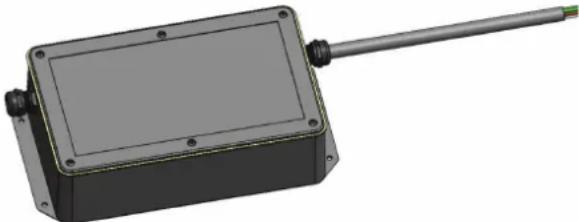 |
| Remote control(with wall holder and screws) |  |
Tools/Parts Required (not Included)
- Bolts for fastening to Ceiling surface
• Phillips Head Screw Driver - Step Ladder
- 2 strong people to help with lifting & assembly
- Spirit Level

WARNING
This heater MUST be installed by an licensed electrical contractor. Do not perform maintenance, or carry out installation or assembly procedure while electrical power is switched on. Wait 2 hours after switching off the heater before handling to prevent touching hot surfaces.
For longest product life and to maintain product appearance, position heater under cover and protect from rain and weather.

IMPORTANT
The appliance must be installed such that the heater head is level with the ground.
The appliance must be mouted on a solid surface, and it is the responsibility of the installer to assess the suitability of the mounting surface.
Minimum distance between heaters measured from edge of heater must be at least 20 inches.

Caution - Glass - Handle with care
- Care must be taken during installation. After removing packaging, glass must be inspected for damage before use. If damage to the appliance is suspected, discontinue use immediately and contact the supplier.
- Check for damage to the appliance before each use. The heater must not be used if the glass panel or any other part of the heater is damaged. If damage to the appliance is suspected, discontinue use immediately and contact the supplier.
- Care must be taken around the appliance to ensure it is not damaged. Ball games that could accidentally hit the heater must not be played around the appliance. To protect appliance do not remove cardboard packaging from head assembly until it is mounted to arm and base.
INSTALLATION INSTRUCTIONS - CEILING MOUNTED HEATER CONTINUED...
Instructions for Single Pole options, including:
• Curved Ceiling Mount Pole 24"
- Straight Ceiling Mount Pole 8"
- Straight Ceiling Mount Pole 24"
- Straight Ceiling Mount Pole 48"
- Unpack all items from shipping cartons and place items on a non-abrasive surface.
To protect appliance do not remove cardboard packaging from head assembly until it is mounted to ceiling.
- Fasten the Pendant Mount Roof Bracket on the ceiling in the desired location, using appropriately sized and type bolts (not included) for the mounting surface. Ensure the bracket is firmly secured to appropriate supports (not only to ceiling panels) with fasteners in 4 opposing holes before proceeding.

IMPORTANT
Fasteners must be chosen by installer to suit mounting structure. Installer is responsible for choosing fasteners appropriate to the loading of the product.
- Attach the chosen Ceiling Mount Pole to the Pendant Mount Roof Bracket using the 4 X Dome Head Screws (M4 - Length: 6mm).
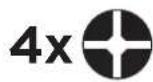
M4 - Length: 6mm
Shown on right are the four options for the Single Ceiling Mount Poles.
- Slide the Round Cap over the Ceiling Mount Pole and attach the it to the Roof Bracket using 2 X Dome Head Screws (M4 - Length: 10mm).

M4 - Length: 10mm

natural_image
Pure diagram of five different types of metal rods or fittings without any text, numbers, or symbols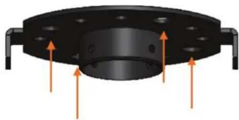
natural_image
Mechanical component with mounting flange and three orange arrows indicating direction (no text or symbols)

natural_image
Pure diagram of a cylindrical object with orange arrows indicating direction, no text or symbols present
natural_image
Four different types of metal rods or connectors shown in a row: curved, three vertical, and three straight (no text or symbols present)
natural_image
3D diagram of a mechanical component with arrows indicating direction (no text or symbols)INSTALLATION INSTRUCTIONS - CEILING MOUNTED HEATER CONTINUED...

WARNING
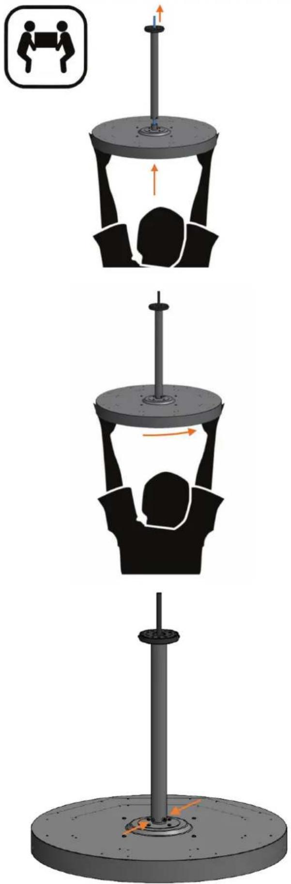
Heavy Item. Min Two Person Lift. Maximum safe lifting 35 lbs per person.
-
Feed the cable through the Ceiling Mount Pole until it has passed through and out into the roof cavity. Feed through the cable slack, and with the help of a second person, lift the Heater Head upwards closer to the Ceiling Mount Pole.
-
Insert the Heater Bracket into the Ceiling Mount Pole by hooking the attached 2X Dome Head Screws (M4 - Length: 6mm) into the slot feature in the Pole.
Note: Screws are pre-assembled to heater head bracket.

natural_image
Mechanical assembly diagram showing a cylindrical component with mounting holes and a highlighted section (no text or symbols)- Fully insert additional 2 X Dome Head Screws (M4 - Length: 6mm) on both sides, and tighten all four screws, to lock heater in place.


M4 - Length: 6mm

natural_image
Mechanical component with four circular mounting holes and a central cylindrical shaft (no text or symbols visible)
GER!
All packaging materials must be removed before turning on the appliance.
natural_image
Three-step diagram showing a person performing a lift exercise on a platform, with no text or symbols present.INSTALLATION INSTRUCTIONS - CEILING MOUNTED HEATER CONTINUED...
Instructions for Twin Pole option:
- Twin Straight Ceiling Mount Pole 24"

natural_image
Pure mechanical component diagrams without any text, numbers, or symbols- Unpack all items from shipping cartons and place items on a non-abrasive surface.
To protect appliance do not remove cardboard packaging from head assembly until it is mounted to ceiling.
- Fasten the Twin Pole Roof Bracket on the ceiling in the desired location, using appropriately sized and type bolts (not included) for the mounting surface. Ensure the bracket is firmly secured to appropriate supports (not only to ceiling panels) with fasteners in 4 opposing holes before proceeding.


IMPORTANT
Fasteners must be chosen by installer to suit mounting structure. Installer is responsible for choosing fasteners appropriate to the loading of the product.
- Place the Twin Pole Cap loosely onto the Twin Straight Ceiling Mount Pole as shown below, and attach the Twin Straight Ceiling Mount Pole to the Twin Pole Roof Bracket using the 4 X Dome Head Screws (M4 - Length: 6mm).

M4 - Length: 6mm

natural_image
Mechanical assembly diagram showing a vertical shaft with flanged ends and a mounting base, with orange arrows indicating force or motion direction (no text or symbols)INSTALLATION INSTRUCTIONS - CEILING MOUNTED HEATER CONTINUED...
- Slide the Twin Pole Cap upwards and attach the it to the Twin Pole Roof Bracket using 2 X Dome Head Screws (M4 - Length: 6mm).


M4 - Length: 6mm

natural_image
3D diagram of a vertical cylindrical mechanical component with two flanged ends and an attached base, showing directional arrows (no text or symbols)
WARNING
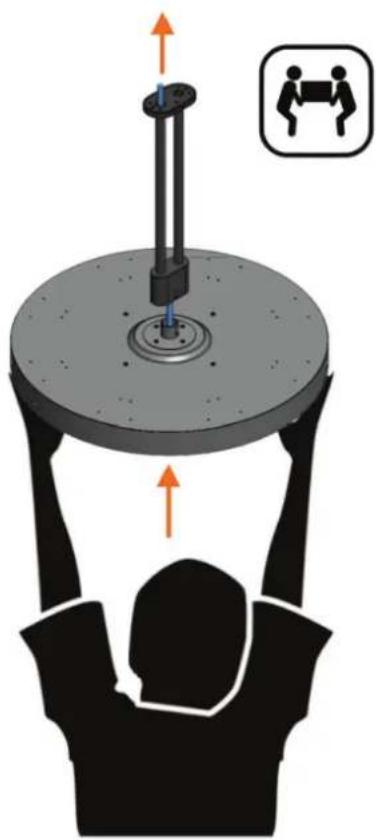
Heavy Item. Min Two Person Lift. Maximum safe lifting 35 lbs per person.
- Feed the cable through one of the poles of the Twin Straight Ceiling Mount Pole until it has passed through and out into the roof cavity. Feed through the cable slack, and with the help of a second person, lift the heater head upwards closer to the Twin Straight Ceiling Mount Pole.
natural_image
Illustration of a person lifting a large cylindrical object with an upward force arrow, accompanied by a small inset showing two people (no text or symbols)INSTALLATION INSTRUCTIONS - CEILING MOUNTED HEATER CONTINUED...
- Insert the Heater Bracket into the Twin Straight Ceiling Mount Pole by hooking the attached 2X Dome Head Screws (M4 - Length: 6mm) into the slot feature in the Pole.

natural_image
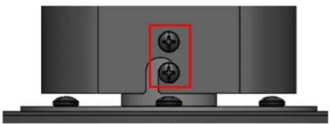
Diagram of a mechanical component with a central valve and orange flow arrow, mounted on a base (no text or symbols)- Fully insert additional 2 X Dome Head Screws (M4 - Length: 6mm) on both sides, and tighten all four screws, to lock heater in place.
2x

M4 - Length: 6mm
natural_image
Mechanical assembly diagram showing two circular components mounted on a base with mounting holes (no text or symbols)8. DANGER!
All packaging materials must be removed before turning on the appliance.

natural_image
Mechanical assembly diagram showing a vertical rod mounted on a platform and a base with rotating components (no text or symbols)Installation Instructions - Wall Mounted Heater
Box 1 Contents
| Eclipse Head AssemblyIncluding pre-assembled 2 x Dome Head Screws (M4 - Length: 6mm) |  |
| Instruction Manual(This Document) |  |
Box 2 Contents
| Wall Mount Pole | 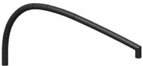 | |
| Wall Bracket |  | |
| Wall Bracket Cover |  | |
| 1 x Round Head Hex Screw(M8 - Length: 15mm) |  | |
| 2 x Dome Head Screw(M6 - Length: 10mm) |  |  |
| 1 x Dome Head Screw(M4 - Length: 10mm) |  | |
| 2 x Dome Head Screws(M4 - Length: 6mm) |  |  |
| 1 x M20x1.5 Blanking Plug |  | |
Box 3 Contents (Sold Separately)
| Eclipse Pendant Control |  |
| Remote control(with wall holder and screws) |  |
Tools/Parts Required (not Included)
- Bolts for fastening to Wall surface
• Phillips Head Screw Driver - Allen Key
- Step Ladder
• 2 strong people to help with lifting - Spirit Level

WARNING
This heater MUST be installed by an licensed electrical contractor. Do not perform maintenance, or carry out installation or assembly procedure while electrical power is switched on. Wait 2 hours after switching off the heater before handling.
For longest product life and to maintain product appearance, position heater under cover and protect from rain and weather.

IMPORTANT
The appliance must be installed such that the heater head is level with the ground.
The appliance must be mouted on a solid surface, and it is the responsibility of the installer to assess the suitability of the mounting surface.
Minimum distance between heaters measured from edge of heater must be at least 20 inches.

Caution - Glass - Handle with care
- Care must be taken during installation. After removing packaging, glass must be inspected for damage before use. If damage to the appliance is suspected, discontinue use immediately and contact the supplier.
- Check for damage to the appliance before each use. The heater must not be used if the glass panel or any other part of the heater is damaged. If damage to the appliance is suspected, discontinue use immediately and contact the supplier.
- Care must be taken around the appliance to ensure it is not damaged. Ball games that could accidentally hit the heater must not be played around the appliance. To protect appliance do not remove cardboard packaging from head assembly until it is mounted to arm and base.
Instructions for Wall Mounted option:
- Unpack all items from shipping cartons and place items on a non-abrasive surface.
To protect appliance do not remove cardboard packaging from head assembly until it is mounted to ceiling.
- Mount the Wall Bracket on the wall in the desired location, using appropriately sized and type bolts (not included) for the mounting surface. Ensure the bracket is firmly secured with fasteners in the 6 holes before proceeding.

IMPORTANT
Fasteners must be chosen by installer to suit mounting structure. Installer is responsible for choosing fasteners appropriate to the loading of the product. Calculated tensile load on each screw is 675 lbf (with FOS of 4).
- Slide the Wall Bracket Cover over the Wall Bracket.

natural_image
3D diagram of a black cylindrical device with orange arrows pointing to its side, mounted on a black frame (no text or symbols)

natural_image
3D diagram of a mechanical component with a blue base and black cylinder, showing an orange arrow indicating direction (no text or symbols)INSTALLATION INSTRUCTIONS - WALL MOUNTED HEATER CONTINUED...
- Fasten the Wall Bracket Cover using 1 X Dome Head Screw (M4 - Length: 10mm).
1x

M4 - Length: 10mm

natural_image
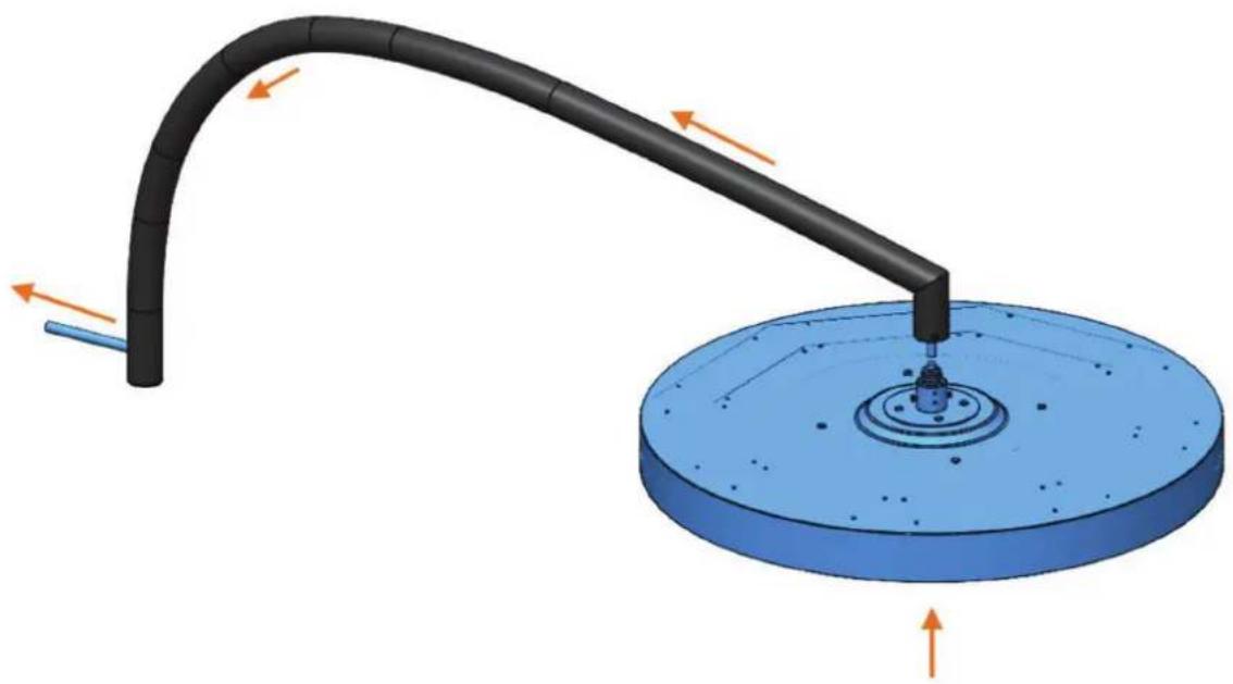
3D rendering of a black cylindrical object with a blue arrow pointing to a small blue dot on its side (no text or symbols)- Feed the cable through the end of the Wall Mount Pole until it has passed through and out the end of the Pole. Feed through the cable slack, bringing the heater head closer to the Wall Mount Pole.
natural_image
3D diagram of a curved pipe mounted on a blue circular base with directional arrows indicating flow or force (no text or symbols)INSTALLATION INSTRUCTIONS - WALL MOUNTED HEATER CONTINUED...
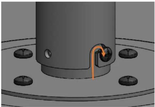
- Insert the Heater Head Bracket into the Wall Mount Pole by hooking the attached 2X Dome Head Screws (M4 - Length: 6mm) into the slot feature in the Pole.
NOTE: Heater head should be positioned so that the bromic logo on the glass is at the front of the heater (furtherst away from the wall).
natural_image
3D rendering of a mechanical component with a central cylindrical shaft and mounting holes, showing a curved orange arrow indicating a movement or force (no text or symbols present)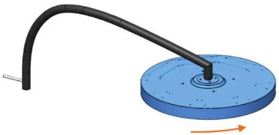
natural_image
3D diagram of a mechanical component with a curved black rod and blue base, showing rotational motion (no text or symbols)- Fully fasten additional 2 X Dome Head Screws (M4 - Length: 6mm) on both sides, and tighten all four screws, to lock heater in place.

M4 - Length: 6mm

natural_image
3D rendering of a black curved pipe attached to a circular base with a small orange arrow indicating force or direction (no text or symbols)
WARNING
Heavy Item. Min Two Person Lift. Maximum safe lifting 35 lbs per person.
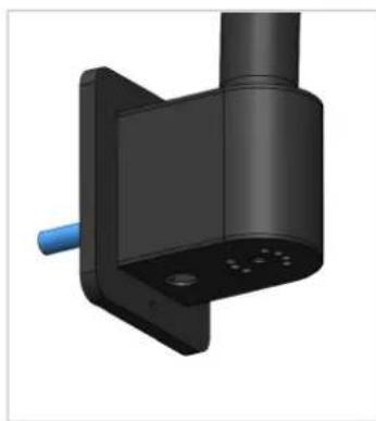
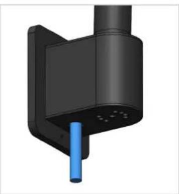
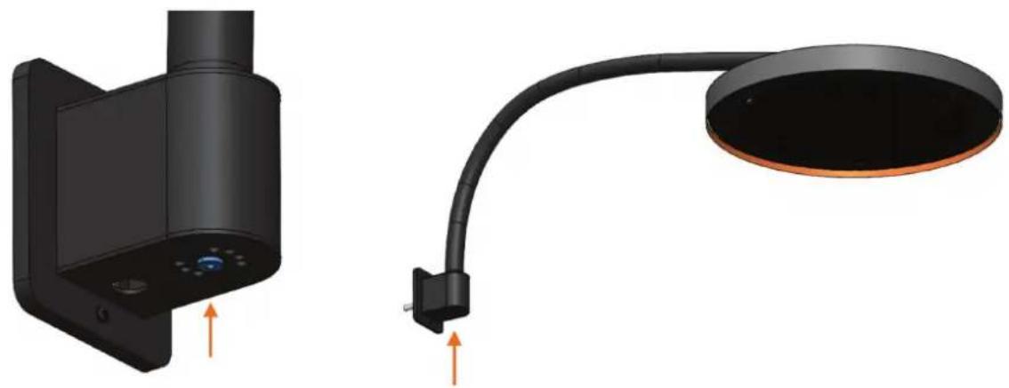
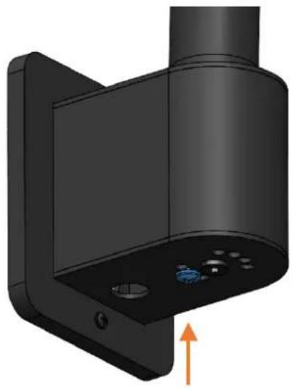
- Attach the Wall Mount Pole to the Wall Bracket. Feed the cable through the back slot of the Wall Mount into the wall cavity, or alternatively, the cable can be fed out of the optional Cable Slot in the underside of the Wall Bracket. In this instance attach an M20 metal cable gland (not supplied) into the same hole from the outside of the bracket.

natural_image
3D rendered mechanical component with black housing and blue handle (no text or symbols)Option 1: Cable into Wall Cavity
natural_image
3D rendered mechanical component with a blue cylindrical pin inserted, no visible text or symbolsOption 2: Cable out of underside
- Fasten the Wall Mount Pole to the Wall Bracket using 1 X Round Head Hex Screw (M8 - Length: 15mm).
1x

M8 - Length: 15mm
natural_image
Illustration of a black office lamp with a mounted device and a curved cable, both without any text or symbols.INSTALLATION INSTRUCTIONS - WALL MOUNTED HEATER CONTINUED...
- Lock the angle of the Wall Mount Pole to the Wall, using 2 X Dome Head Screw (M6 - Length: 10mm). The Wall Bracket angle can be adjusted up to 45° from the wall on each side.
2x

M6 - Length: 10mm
natural_image
3D rendering of a mechanical component with mounting holes and a vertical shaft, showing an orange arrow indicating direction (no text or symbols)
natural_image
3D rendering of a black adjustable lamp with an orange arrow pointing upward (no text or symbols)- If the cable has been routed into the wall cavity, Insert the Cable plug into the optional cable slot.

natural_image
3D rendering of a black mechanical component with a blue circular knob and orange arrow indicator (no text or symbols)12. DANGER!
All packaging materials must be removed before turning on the appliance.
IMPORTANT NOTES & WARNINGS

WARNING
This heater MUST be installed by an authorised/licenced person. Do not perform maintenance, or carry out installation or assembly procedure while electrical power is switched on.

DANGER
ELECTRICAL SHOCK HAZARD! Serious injury or death may occur. Disconnect from electrical supply before installing or servicing this heater. Read and follow installation clearance requirements outlined in this manual. The appliance MUST be connected to a properly grounded electrical source. Isolate mains before installing. Use only with a properly secured heater.

IMPORTANT
Pendant Heater controls generate heat during operation. Controls MUST be mounted in a clean, dry and well-ventilated position, with clearance on all sides, and where ambient temperature does not exceed 86^ F. Controls MUST remain cool at all times.
Controls MUST NOT be installed in a confined space, close to other heat generating appliances or in the case of a multi-control installation, a minimum clearance of 1 ft between all sides of adjacent controls. For further questions please contact Bromic technical support services.
Check product label for correct voltage and wattage to ensure power source conforms to the heater's requirements.
Use appropriate power supply cables for the heaters' voltage and wattage. The fixed wiring must be positioned away from & protected from the enclosure of the heater.
Make all connections in accordance with local electrical code regulations. For outdoor installation, all connections must be made in accordance with local electrical code regulations for outdoor wiring. Only use wiring components approved for outdoor use with minimum IP54 rating.
PLUG AND SUPPLY CORD: Use an appropriately rated plug and supply cord - check the power requirements of the connected loads. Socket outlet used must be near the equipment.
Study the WIRING DIAGRAM at the end of this document before starting installation.
OVER CURRENT DEVICE: The outputs are NOT protected against short circuits or extra-currents which can damage the electronic board. Evaluate the characteristics of the connected loads and apply the appropriate safety devices to the power line.
ISOLATION SWITCH: This product does not have a switch for electrical disconnection. A means for disconnection of the heater must be incorporated in the wall socket & fixed wiring according to the local electrical codes.
The Pendant Heater Control must be mounted using the following guidelines:
- It must be fixed on surfaces which cannot be damaged by high temperature or UV.
- It must be fixed in a well-ventilated location where ambient temperature does not exceed 86^ .
- Connection cables must be protected against any accidental impacts, using proper piping/conduits.
- Do not cover the product.
- Do not use or store flammable materials close to the product.
ELECTRICAL INSTALLATION - PENDANT HEATERS CONTROL

IMPORTANT
The controller must be installed in a space with free and open air flow which ensures ambient temperature does not exceed 86^ F.
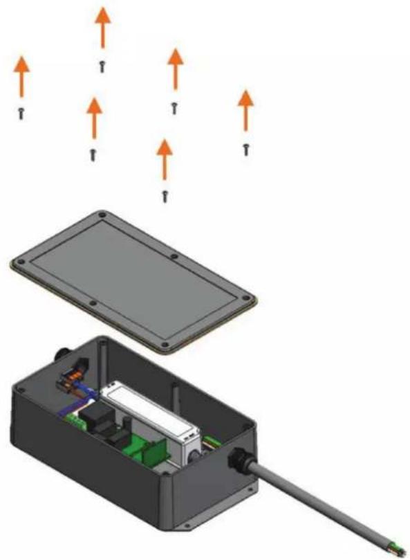
- Open cover to the Pendant Control Box, by removing 6x Oval head screws (#4-40 - Length: 1/2") from the cover.
natural_image
3D diagram of an electronic device showing internal components and airflow direction arrows (no text or symbols)
DANGER
The Power source MUST NOT be live when installing the Eclipse Control Box.
- Wire the power supply (not included) as per the wiring diagram. The Live, Neutral and Ground supply wires connect to their corresponding L, N and Ground ⏻ WAGO 3-way quick connectors.

ELECTRICAL INSTALLATION - PENDANT HEATERS CONTROL
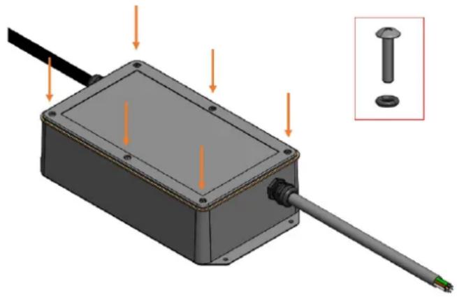
- Refit cover to the box, ensuring the 6 X M3 O-Rings are present on the 6x Oval head screws (#4-40 - Length: 1/2").

4-40 - Length: 1/2" (Preassembled)


M3 - O-Ring (Preassembled)

DANGER
The Power source MUST NOT be live when installing the Eclipse Control Box.
- Wire the 6 Core Cable from the Eclipse Control Box to the Corresponding coloured wires on the 6 core cable from the Eclipse Heater Head, according to local Electrical Code regulations.
Ensure connection is adequately protected from the environment using an IP54 (or better) cover (not included) suitable for the application.
natural_image
3D mechanical assembly diagram showing a rectangular component with mounting holes and a shaft, with an inset view of a bolt (no text or symbols present)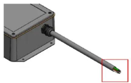
natural_image
3D rendering of a mechanical component with a green pin inserted, no visible text or symbolsPower cable from controller (Supplied with controller)
Junction box & terminals (Provided by installer)
Power cable from heater (Supplied with heater)
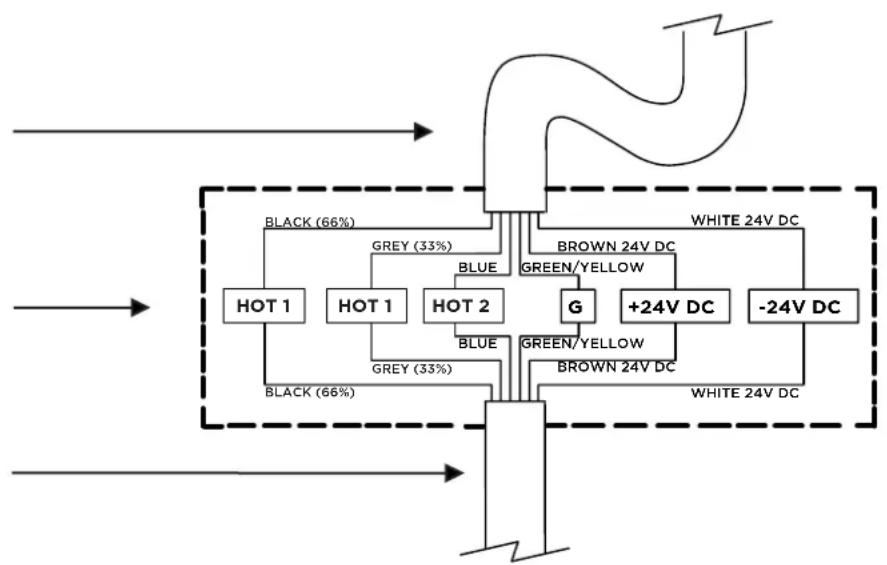
flowchart
graph TD
    A["Black (66%)"] --> B["HOT 1"]
    C["Grey (33%)"] --> D["HOT 1"]
    E["BLUE"] --> F["HOT 2"]
    G["BROWN 24V DC"] --> H["G"]
    I["WHITE 24V DC"] --> J["+24V DC"]
    K["-24V DC"] --> L["WHITE 24V DC"]
    M["GREEN/YELLOW"] --> N["G"]
    O["GREEN/YELLOW"] --> P["BROWN 24V DC"]
    Q["BLACK (66%)"] --> R["HOT 1"]
    S["GREY (33%)"] --> T["HOT 2"]
    U["BLE"] --> V["BLUE"]
    W["BLE"] --> X["BLUE"]
    Y["BLE"] --> Z["BLUE"]
    AA["BLE"] --> AB["BLUE"]

IMPORTANT
The controller must be installed in a space with free and open air flow which ensures ambient temperature does not exceed 86°.
- Mount the Pendant Heater Control to the desired ceiling or wall location using appropriately sized and type screws (not included) for the mounting surface. Ensure the Pendant Heater Control is firmly secured with fasteners in the 4 holes before proceeding.

natural_image
3D rendering of a rectangular electronic enclosure with mounting holes and a cable, showing internal components and wiring (no text or symbols)FOR INSTALLATION USING BROMIC ECLIPSE PENDANT CONTROL
(Bromic Eclipse Pendant Control supplied separately)
ONLY TO BE INSTALLED & SERVICED BY LICENSED & AUTHORIZED TECHNICIAN.
APPLIANCE MANUAL MUST BE READ BEFORE INSTALLING OR SERVICING THIS PRODUCT.
Power supply 220-240V - a.c.
Minimum Circuit Ampacity 17A.
(Provided by installer)
NOTES:
- Supply connection must be protected with appropriate safety device, that includes isolation switch.
- Suitable junction box for connection to be supplied by installer.
- Control box must be located in an environment of no more than 86°F ambient, away from other heat sources and separation clearances maintained.
- Wiring must be completed according to local electrical code.
- 24VDC lighting circuit is to be separated inside the junction box from 220-240VAC circuits.
- Electrical installation must ensure earth continuity is checked.
'MEM' button for re-pairing remote to Heater control PCB
Button for re-pairing remote to LED PCB
Power cable from controller (Supplied with controller)
Junction box & terminals (Provided by installer)
Power cable from heater (Supplied with heater)

PENDANT HEATER CONTROL WIRING DIAGRAM
FOR INSTALLATION NOT USING BROMIC ECLIPSE PENDANT CONTROL
ONLY TO BE INSTALLED & SERVICED BY LICENSED & AUTHORIZED TECHNICIAN. APPLIANCE MANUAL MUST BE READ BEFORE INSTALLING OR SERVICING THIS PRODUCT.

flowchart
graph TD
    A["Power supply to suit rated input of transformer (Provided by installer)"] --> B["LED Transformer Output: 24V DC, Power Rating: 25W Minimum (Provided by installer)"]
    B --> C["Transformer wires (Provided by installer)"]
    C --> D["AC IN"]
    C --> E["TRANSFORMER OUTPUT 24V DC, 25W MIN"]
    C --> F["DC OUT 24V"]
    G["Power supply 220-240V - a.c. Minimum Circuit Ampacity 17A. (Provided by installer)"] --> H["Junction box & terminals (Provided by installer)"]
    H --> I["HOT 1"]
    H --> J["HOT 1 HOT 2"]
    H --> K["G"]
    H --> L["BLE"]
    H --> M["GREEN/YELLOW"]
    H --> N["BROWN 24V DC"]
    H --> O["+24V DC"]
    H --> P["-24V DC"]
    H --> Q["WHITE 24V DC"]
    R["To control elements independently L1 (66% element) & L2 (33% element) need independent 220-240V power supplies."] --> S["Power cable from heater (Supplied with heater)"]
    S --> T["BLACK (66%)"]
    S --> U["GREY (33%)"]
    S --> V["GREND"]
NOTES:
- Supply connection must be protected with appropriate safety device, that includes isolation switch.
- Suitable junction box for connection to be supplied by installer.
- Control must be located in an environment of no more than 86^ F ambient, away from other heat sources and separation clearances maintained.
- Wiring must be completed according to local electrical code.
- 24V DC lighting circuit is to be separated inside the junction box from 220-240VAC circuits.
- Electrical installation must ensure earth continuity is checked.
REMOTE CONTROL FUNCTIONS
(SUPPLIED WITH BROMIC ECLIPSE PENDANT CONTROL)

bar
BROMIC® HEATING | Heater | Percentage (%) | | :--- | :--- | | Heater 100% - Heater output at full (100%) | 100 | | Heater 66% - Heater output at 66% of total | 66 | | Heater 33% - Heater output at 33% of total | 33 | | Heater OFF - Heater off | 0 | | Lights 100% (DIM^) - Lights output at full (100%) or HOLD to DIM Up | 100 | | Lights 50% - Light output at 50% of total | 50 | | Lights OFF (DIM^) - Light off or HOLD to DIM Down | 0 |TURNING THE APPLIANCE ON
-
Using the Remote Control, select the desired Heater setting:
-
Heater 100% - Heater output at full (100%).
- Heater 66% - Heater output at 66% of total.
-
Heater 33% - Heater output at 33% of total.
-
Using the Remote Control, select the desired Light setting:
-
Lights 100% - Lights output at full (100%).
-
Lights 50% - Light output at 50% of total.
-
To Lower lights, Press & Hold OFF DIM^ until the lights have lowered to the desired level.
-
To Brighten lights, Press & Hold 100% DIM ^^ until the lights have increased to the desired level.
NOTE: It is normal to observe a small dim spot on the LED at the location where the LED joins together.
TURNING THE APPLIANCE OFF
- Using the Remote Control, press on the desired Heater setting:
- Heater OFF - Heater off.
- Using the Remote Control, select the desired Light setting:
- Lights OFF (DIM ^^ ) - Light off.

natural_image
Silhouette of a person pointing at a desk lamp (no text or symbols visible)REMOTE CONTROL BATTERY
- Keep the batteries out of reach of children.
- Call a doctor immediately if a battery is swallowed.
- Explosion hazard if the battery is substituted incorrectly.
- Replace the battery with a CR2430 type battery only.
- Battery is not rechargeable and must not be recharged.
- Do not throw the battery away with household rubbish.
- The supply terminals are not to be short-circuited.
- Battery must be inserted with correct polarity (+/-)!
• Always wrap the battery up, both when it is being stored and when it is being disposed of. The battery should not come into contact with other metal objects as it could cause the battery to run down, catch fire or be damaged.
- Dispose of damaged or finished batteries immediately in compliance with the law. To this end, contact the authorities for safeguarding the environment or the centre for disposing of waste materials in your area.
To replace the battery:
- Remove screw and open the back cover of the remote.
- Take the old battery out and put the new one in the same way.
PAIRING REMOTE CONTROL TO HEATER PCB (TOP 4 BUTTONS OF REMOTE).
WARNING: MUST ONLY BE SERVICED BY LICENSED & AUTHORIZED TECHNICIAN.

DANGER
ELECTRICAL SHOCK HAZARD! Serious injury or death may occur. Do not touch any components other than specified below. Protective equipment including insulated gloves must be worn.
- Open cover to the Pendant Control Box, by removing 6x Oval head screws (#4-40 - Length: 1/2") from the cover.
- Switch the power supply to the Eclipse Pendant Control ON.
- With the Eclipse Pendant Control powered ON, PRESS & HOLD the middle 'MEM' button on the large heater control PCB. (A long "Beep" sound should be heard whilst the button is held down).

(hold)
'MEM' button
Whilst the 'MEM' button is held down, SHORT PRESS the Heater 100% button on the remote control. (Three short "Beep" sounds should be heard to indicate the remote has been paired successfully.

1s (short)
- Refit cover to the box, ensuring the 6 X M3 O-Rings are present on the 6x Oval head screws (#4-40 - Length: 1/2").

natural_image
3D diagram of an open electronic device with internal components and upward arrows indicating motion (no text or symbols)
OPERATING INSTRUCTIONS
PAIRING REMOTE CONTROL TO LED PCB (BOTTOM 3 BUTTONS OF REMOTE).
WARNING: MUST ONLY BE SERVICED BY LICENSED & AUTHORIZED TECHNICIAN.

DANGER
ELECTRICAL SHOCK HAZARD! Serious injury or death may occur. Do not touch any components other than specified below. Protective equipment including insulated gloves must be worn.

natural_image
3D diagram of an open electronic device showing internal components and housing (no text or symbols)- Open cover to the Pendant Control Box, by removing 6x Oval head screws (#4-40 - Length: 1/2") from the cover.
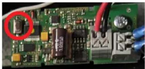
- Locate the small black button on the small LED PCB (shown in image on right), and the small button mid way down the back face of the remote (for later steps).
- Switch the power supply to the Eclipse Pendant Control ON.

natural_image
Interior view of an electronic device enclosure showing exposed circuit board, capacitors, and wiring (no visible text or symbols)- Using a thin item (e.g. paper clip/needle), SHORT PRESS the small button on the rear of the remote.

Remote Reset button
1s (short)

Within 5 seconds of pressing the small button on the rear of the remote, press the small black button on the LED PCB 3 times, holding the button down on the third press. (2X SHORT PRESS followed by 1X PRESS & HOLD)

1

2
3(hold)
natural_image
Close-up of a green printed circuit board with electronic components and red wires, no visible text or symbolsWhile the LED PCB button is held down, SHORT PRESS the Lights 100% button on the remote control.
1s (short)

- The LED on the Heater head will flash 3 times to indicate the remote is paired.
- Refit cover to the box, ensuring the 6 X M3 O-Rings are present on the 6x Oval head screws (#4-40 - Length: 1/2").

natural_image
3D rendering of a rectangular electronic component with a rod and screw, showing mounting holes and wiring (no text or symbols)IMPORTANT NOTES & WARNINGS

WARNING
This heater MUST be installed by an authorised/ licenced person. Do not perform maintenance, or carry out installation or assembly procedure while electrical power is switched on.

DANGER
ELECTRICAL SHOCK HAZARD! Serious injury or death may occur. Disconnect from electrical supply before installing or servicing this heater. Read and follow installation clearance requirements outlined in this manual. The appliance MUST be connected to a properly grounded electrical source. Isolate mains before installing. Use only with a properly secured heater.

IMPORTANT
Check product label for correct voltage and wattage to ensure power source conforms to the heater's requirements.
Make all connections in accordance with local electrical code regulations. For outdoor installation, all connections must be made in accordance with local electrical code regulations for outdoor wiring.
OVERCURRENT DEVICE: The outputs are NOT protected against short circuits or extra-currents which can damage the electronic board. Evaluate the characteristics of the connected loads and apply the appropriate safety devices to the power line.
Check surrounding area of heater for hazards before turning on.
MAINTENANCE
- For longest product life, and to maintain product appearance, mount heater under cover and protect from rain and weather whenever possible.
- Before cleaning ensure the appliance is off and has been off for at least 2 hours after operation. The heater must be cool to touch before cleaning can begin.
- The exterior housing of the heater should be cleaned regularly. Use a clean, soft, damp cloth. Salt in the air can cause rusting of metal, especially at locations near the coast. Additional cleaning of the heater with a soft damp cloth fortnightly will aid in maintaining the product's appearance. Do not clean heater with cleaners that are combustible or corrosive.
- Improper cleaning of the front of the appliance can cause scratching and reduce the appearance of the appliance. Below guidelines must be read before cleaning the front of the appliance and must be followed to maintain the quality of the surface finish.
| DO NOT DO | |
| Do not use harsh cleaning pads or sharp tools.Do not use harsh cleaning chemicals.Do not spray the appliance with water for cleaning. | Use a clean, soft, damp microfibre cloth.Use lukewarm water and a mild dish washing detergent. |
| Do not use a dry cloth or your hand to wipe clean the surface.Using a dry cloth or your hand to clean the surface will rub dirt and dust into the surface and may cause scratching or damage. | Use a microfibre cloth in the lukewarm water solution.Rinse out the cloth frequently to remove any dirt and dust from the cloth to avoid scratching the surface. |
| Do not apply pressure and rub the surface.Do not apply continuous, erratic scrubbing. | Gently wipe the microfibre cloth across the surface.Apply minimum pressure to avoid scratching.Minimise contact with the surface.Use the same directional stroke, lift hand and repeat. |
| Do not buff dry with a cloth that could cause scratching. | Allow surface to air dry. |
TROUBLESHOOTING
| SYMPTOM POSSIBLE CAUSE (S) CORRECTIVE ACTION | ||
| No heat 1. Incorrect heater setting chosen2. Incorrect Voltage.3. No power.4. No/low batteries in remote.5. Remote too far.6. Radio interference.7. Remote not paired or faulty control. | 1. Choose heat setting using remote (33%, 66% or 100%).2. Connect to 220-240V power supply.3. Check connection to power supply.4. Change remote batteries.5. Move remote closer to heater.6. Move remote closer to heater, disable other radio emitting devices.7. Pair remote to heater PCB. | |
| Not enough heat 1. Incorrect heater setting chosen.2. Heater installed too high.3. Heater too small for application. | 1. Choose higher heat setting using remote (66% or 100%).2. Check height is according to instructions.3. Add additional heater(s). | |
| Too much heat 1. Incorrect heater setting chosen.2. Heater installed too low. | 1. Choose lower heat setting using remote (66% or 33%).2. Check height is according to instructions. | |
| No Light 1. Incorrect lighting setting chosen.2. Incorrect Voltage.3. No power.4. No/low batteries in remote.5. Remote too far.6. Radio interference.7. Remote not paired or faulty control. | 1. Choose lighting setting using remote (50% or 100% (DIM^)).2. Connect to 220-240V power supply.3. Check connection to power supply.4. Change remote batteries.5. Move remote closer to heater.6. Move remote closer to heater, disable other radio emitting devices.7. Pair remote to LED PCB. | |
| Not enough Light 1. Incorrect lighting setting chosen.2. Light too small for application. | 1. Choose higher lighting setting using remote (50% or 100% (DIM^)).2. Add additional light(s). | |
| Too much Light 1. Incorrect lighting setting chosen.1. Choose lower heat setting using remote (50% or OFF (DIM^)). | ||
REPLACEMENT PARTS
| Part Number | Description | Part Number | Description |
| BH0920001-1 | Eclipse Electric Heater Head (US) | BH3230006 | Wall Mount Pole Eclipse Electric |
| BH3230001 | Straight Ceiling Mount Pole 8” Elcipse Electric | BH3230007-1 | Eclipse Electric Pendant Control (US) |
| BH3230002 | Straight Ceiling Mount Pole 24” Elcipse Electric | BH8380009 | Screw Set Ceiling Mount Pole Eclipse Electric |
| BH3230003 | Twin Straight Ceiling Mount Pole 24” Elcipse Electric | BH8380010 | Screw Set Wall Mount Pole Eclipse Electric |
| BH3230004 | Curved Ceiling Mount Pole 24” Elcipse Electric | BH8380011 | Remote for Eclipse Electric Control (US) |
| BH3230005 | Straight Ceiling Mount Pole 48” Elcipse Electric | - | - |
- ECLIPSE SMART-HEAT™ ELECTRIC
- INSTRUCTION MANUAL
- DANGER, ⚠WARNING, ⚠IMPORTANT
- Correct disposal of this product
- CONTENT
- IMPORTANT NOTES & WARNINGS 4-5
- PRODUCT OVERVIEW 6
- KEY DIMENSIONS & CLEARANCES 7
- INSTALLATION INSTRUCTIONS - CEILING MOUNTED HEATER 8-14
- INSTALLATION INSTRUCTIONS - WALL MOUNTED HEATER 15-22
- ELECTRICAL INSTALLATION - PENDANT HEATER CONTROLS 23-25
- PENDANT HEATER CONTROL WIRING DIAGRAM 26-27
- OPERATION INSTRUCTIONS 28-30
- MAINTENANCE & SERVICING 31
- TROUBLESHOOTING 32
- REPLACEMENT PARTS 32
- IMPORTANT NOTES & WARNINGS
- WARNING
- IMPORTANT NOTES AND WARNINGS CONTINUED ...
- SAVE THESE INSTRUCTIONS
- PRODUCT DESCRIPTION
- PRODUCT FEATURES
- Contents Packed in (3) Boxes
- Tools/Parts Required (not Included)
- IMPORTANT
- Caution - Glass - Handle with care
- INSTALLATION INSTRUCTIONS - CEILING MOUNTED HEATER CONTINUED...
- Instructions for Single Pole options, including:
- GER!
- Instructions for Twin Pole option:
- - Twin Straight Ceiling Mount Pole 24"
- DANGER!
- Installation Instructions - Wall Mounted Heater
- Instructions for Wall Mounted option:
- INSTALLATION INSTRUCTIONS - WALL MOUNTED HEATER CONTINUED...
- DANGER!
- DANGER
- ELECTRICAL INSTALLATION - PENDANT HEATERS CONTROL
- 4-40 - Length: 1/2" (Preassembled)
- FOR INSTALLATION USING BROMIC ECLIPSE PENDANT CONTROL
- NOTES:
- PENDANT HEATER CONTROL WIRING DIAGRAM
- FOR INSTALLATION NOT USING BROMIC ECLIPSE PENDANT CONTROL
- REMOTE CONTROL FUNCTIONS
- TURNING THE APPLIANCE ON
- TURNING THE APPLIANCE OFF
- REMOTE CONTROL BATTERY
- PAIRING REMOTE CONTROL TO HEATER PCB (TOP 4 BUTTONS OF REMOTE).
- (hold)
- 1s (short)
- OPERATING INSTRUCTIONS
- PAIRING REMOTE CONTROL TO LED PCB (BOTTOM 3 BUTTONS OF REMOTE).
- 3(hold)
- MAINTENANCE
- TROUBLESHOOTING
- REPLACEMENT PARTS
Brand : Bromic
Model : Eclipse Smart-Heat BH0920001
Category : Heating