
DV14DSL - Drill HiKOKI - Free user manual and instructions
Find the device manual for free DV14DSL HiKOKI in PDF.

| Brand | HiKOKI (formerly Hitachi) |
| Model | DV14DSL |
| Product Type | Cordless Impact Driver Drill |
| Power Source | Battery (14.4 V Li-ion) |
| No-load Speed (Low/High) | 0 – 400 / 0 – 1400/min |
| No-load Impact Rate (Low/High) | 0 – 5600 / 0 – 19600/min |
| Drilling Capacity (Brick) | 13 mm |
| Drilling Capacity (Wood) | 36 mm |
| Drilling Capacity (Metal Steel) | 13 mm |
| Driving Capacity (Machine Screw) | 6 mm |
| Driving Capacity (Wood Screw) | 6.8 mm dia. x 50 mm L (pilot hole required) |
| Weight | 1.7 kg |
| Battery Model | BSL1430 (14.4 V, 3.0 Ah, 8 cells) |
| Charger Model | UC18YRSL (14.4 V, 0.6 kg) |
| Charging Time (at 20°C) | Approx. 45 min |
| Clutch Torque Settings | 22 positions (numbers 1-22 and black dots) |
| Operating Modes | Screwdriver, Drill, Impact Drill |
| Speed Control | Variable speed trigger |
| Gear Shift | Two-speed (Low/High) |
| Chuck Type | Keyless chuck |
| LED Light | Yes, with on/off switch, auto-off after 15 min |
| Remaining Battery Indicator | Yes, 3-level indicator |
| Automatic Spindle Lock | Yes |
| Belt Hook | Yes, removable |
| Included Accessories | Plus driver bit (#2 x 65L), charger, 2 batteries (BSL1430), plastic case, battery cover |
Frequently Asked Questions - DV14DSL HiKOKI
User questions about DV14DSL HiKOKI
0 question about this device. Answer the ones you know or ask your own.
Ask a new question about this device
Download the instructions for your Drill in PDF format for free! Find your manual DV14DSL - HiKOKI and take your electronic device back in hand. On this page are published all the documents necessary for the use of your device. DV14DSL by HiKOKI.
USER MANUAL DV14DSL HiKOKI
Cordless Impact Driver Drill
충전 임팩트 드라이버 드릴
DV 14DSL · DV 18DSL
Handling instructions
취급 설명서
natural_image
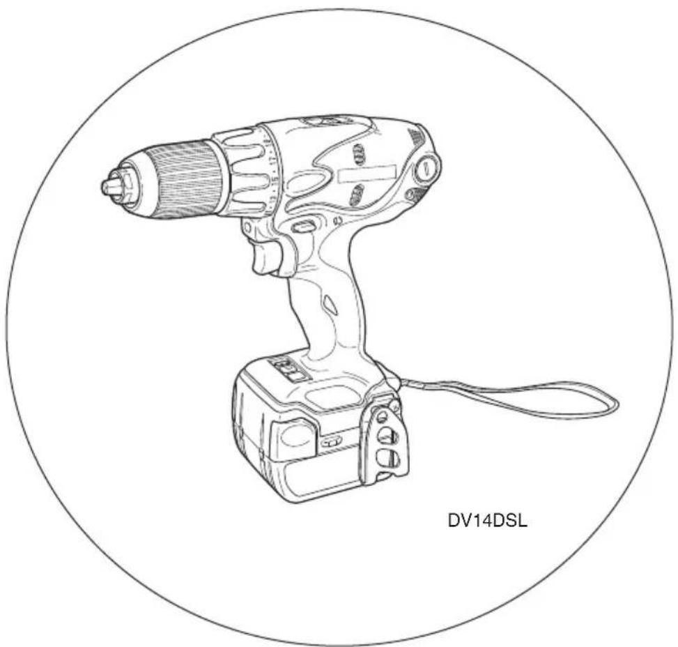
Line drawing of a DV14DSL handheld electric drill (no text or symbols on the device itself)Read through carefully and understand these instructions before use.
2
3
4
5
6
7

8

9
10
11

12


natural_image
Illustration of a hand using a tool to interact with a human head (no text or symbols present)
Read all instructions
Failure to follow all instructions listed below may result in electric shock, fire and/or serious injury.
The term "power tool" in all of the warnings listed below refers to your mains operated (corded) power tool or battery operated (cordless) power tool.
SAVE THESE INSTRUCTIONS
1) Work area safety
a) Keep work area clean and well lit.
Cluttered or dark areas invite accidents.
b) Do not operate power tools in explosive atmospheres, such as in the presence of flammable liquids, gases or dust.
Power tools create sparks which may ignite the dust or fumes.
c) Keep children and bystanders away while operating a power tool.
Distractions can cause you to lose control.
2) Electrical safety
a) Power tool plugs must match the outlet.
Never modify the plug in any way.
Do not use any adapter plugs with earthed (grounded) power tools.
Unmodified plugs and matching outlets will reduce risk of electric shock.
b) Avoid body contact with earthed or grounded surfaces, such as pipes, radiators, ranges and refrigerators. There is an increased risk of electric shock if your body is earthed or grounded.
c) Do not expose power tools to rain or wet conditions.
Water entering a power tool will increase the risk of electric shock.
d) Do not abuse the cord. Never use the cord for carrying, pulling or unplugging the power tool. Keep cord away from heat, oil, sharp edges or moving parts.
Damaged or entangled cords increase the risk of electric shock.
e) When operating a power tool outdoors, use an extension cord suitable for outdoor use.
Use of a cord suitable for outdoor use reduces the risk of electric shock.
3) Personal safety
a) Stay alert, watch what you are doing and use common sense when operating a power tool.
Do not use a power tool while you are tired or under the influence of drugs, alcohol or medication.
A moment of inattention while operating power tools may result in serious personal injury.
b) Use personal protective equipment. Always wear eye protection.
Protective equipment such as dust mask, non-skid safety shoes, hard hat, or hearing protection used for appropriate conditions will reduce personal injuries.
c) Prevent unintentional starting. Ensure the switch is in the off-position before connecting to power source and/or battery pack, picking up or carrying the tool.
Carrying power tools with your finger on the switch or energising power tools that have the switch on invites accidents.
d) Remove any adjusting key or wrench before turning the power tool on.
A wrench or a key left attached to a rotating part of the power tool may result in personal injury.
e) Do not overreach. Keep proper footing and balance at all times.
This enables better control of the power tool in unexpected situations.
f) Dress properly. Do not wear loose clothing or jewellery. Keep your hair, clothing and gloves away from moving parts.
Loose clothes, jewellery or long hair can be caught in moving parts.
g) If devices are provided for the connection of dust extraction and collection facilities, ensure these are connected and properly used.
Use of dust collection can reduce dust related hazards.
4) Power tool use and care
a) Do not force the power tool. Use the correct power tool for your application.
The correct power tool will do the job better and safer at the rate for which it was designed.
b) Do not use the power tool if the switch does not turn it on and off.
Any power tool that cannot be controlled with the switch is dangerous and must be repaired.
c) Disconnect the plug from the power source and/or the battery pack from the power tool before making any adjustments, changing accessories, or storing power tools.
Such preventive safety measures reduce the risk of starting the power tool accidentally.
d) Store idle power tools out of the reach of children and do not allow persons unfamiliar with the power tool or these instructions to operate the power tool.
Power tools are dangerous in the hands of untrained users.
e) Maintain power tools. Check for misalignment or binding of moving parts, breakage of parts and any other condition that may affect the power tools' operation.
If damaged, have the power tool repaired before use.
Many accidents are caused by poorly maintained power tools.
f) Keep cutting tools sharp and clean.
Properly maintained cutting tools with sharp cutting edges are less likely to bind and are easier to control.
g) Use the power tool, accessories and tool bits etc. in accordance with these instructions, taking into account the working conditions and the work to be performed.
Use of the power tool for operations different from those intended could result in a hazardous situation.
5) Battery tool use and care
a) Ensure the switch is in the off position before inserting battery pack.
Inserting the battery pack into power tools that have the switch on invites accidents.
b) Recharge only with the charger specified by the manufacturer.
A charger that is suitable for one type of battery pack may create a risk of fire when used with another battery pack.
c) Use power tools only with specifically designated battery packs.
Use of any other battery packs may create a risk of injury and fire.
d) When battery pack is not in use, keep it away from other metal objects like paper clips, coins, keys, nails, screws, or other small metal objects that can make a connection from one terminal to another.
Shorting the battery terminals together may cause burns or a fire.
e) Under abusive conditions, liquid may be ejected from the battery; avoid contact. If contact accidentally occurs, flush with water. If liquid contacts eyes, additionally seek medical help.
Liquid ejected from the battery may cause irritation or burns.
6) Service
a) Have your power tool serviced by a qualified repair person using only identical replacement parts.
This will ensure that the safety of the power tool is maintained.
PRECAUTION
Keep children and infirm persons away.
When not in use, tools should be stored out of reach of children and infirm persons.
PRECAUTIONS FOR CORDLESS IMPACT DRIVER DRILL
-
Always charge the battery at a temperature of 0 – 40°C. A temperature of less than 0°C will result in over charging which is dangerous. The battery cannot be charged at a temperature higher than 40°C. The most suitable temperature for charging is that of 20 – 25°C.
-
When one charging is completed, leave the charger for about 15 minutes before the next charging of battery. Do not charge more than two batteries consecutively.
-
Do not allow foreign matter to enter the hole for connecting the rechargeable battery.
-
Never disassemble the rechargeable battery and charger.
-
Never short-circuit the rechargeable battery. Short-circuiting the battery will cause a great electric current and overheat. It results in burn or damage to the battery.
-
Do not dispose of the battery in fire. If the battery is burnt, it may explode.
-
When drilling in wall, floor or ceiling, check for buried electric power cord, etc.
-
Bring the battery to the shop from which it was purchased as soon as the post-charging battery life becomes too short for practical use. Do not dispose of the exhausted battery.
-
Using an exhausted battery will damage the charger.
-
Do not insert object into the air ventilation slots of the charger.
Inserting metal objects or inflammables into the charger air ventilation slots will result in electrical shock hazard or damaged charger.
-
When mounting a bit into the keyless chuck, tighten the sleeve adequately. If the sleeve is not tight, the bit may slip or fall out, causing injury.
-
This product contains a strong permanent magnet in the motor.
Observe the following precautions regarding adhering of chips to the tool and the effect of the permanent magnet on electronic devices.
CAUTION:
○Do not place the tool on a workbench or work area where metal chips are present.
The chips may adhere to the tool, resulting in injury or malfunction.
○ If chips have adhered to the tool, do not touch it. Remove the chips with a brush.
Failure to do so may result in injury.
○ If you use a pacemaker or other electronic medical device, do not operate or approach the tool.
Operation of the electronic device may be affected.
○Do not use the tool in the vicinity of precision devices such as cell phones, magnetic cards or electronic memory media.
Doing so may lead to misoperation, malfunction or loss of data.
CAUTION ON LITHIUM-ION BATTERY
To extend the lifetime, the lithium-ion battery equips with the protection function to stop the output.
In the cases of 1 and 2 described below, when using this product, even if you are pulling the switch, the motor may stop. This is not the trouble but the result of protection function.
-
When the battery power remaining runs out, the motor stops. In such case, charge it up immediately.
-
If the tool is overloaded, the motor may stop. In this case, release the switch of tool and eliminate causes of overloading. After that, you can use it again.
Furthermore, please heed the following warning and caution.
WARNING
In order to prevent any battery leakage, heat generation, smoke emission, explosion and ignition beforehand, please be sure to heed the following precautions.
- Make sure that swarf and dust do not collect on the battery.
○During work make sure that swarf and dust do not fall on the battery.
○Make sure that any swarf and dust falling on the power tool during work do not collect on the battery.
○Do not store an unused battery in a location exposed to swarf and dust.
Before storing a battery, remove any swarf and dust that may adhere to it and do not store it together with metal parts (screws, nails, etc.).
2. Do not pierce battery with a sharp object such as a nail, strike with a hammer, step on, throw or subject the battery to severe physical shock.
3. Do not use an apparently damaged or deformed battery.
4. Do not use the battery in reverse polarity.
5. Do not connect directly to an electrical outlets or car cigarette lighter sockets.
6. Do not use the battery for a purpose other than those specified.
7. If the battery charging fails to complete even when a specified recharging time has elapsed, immediately stop further recharging.
8. Do not put or subject the battery to high temperatures or high pressure such as into a microwave oven, dryer, or high pressure container.
9. Keep away from fire immediately when leakage or foul odor are detected.
10. Do not use in a location where strong static electricity generates.
11. If there is battery leakage, foul odor, heat generated, discolored or deformed, or in any way appears abnormal during use, recharging or storage, immediately remove it from the equipment or battery charger, and stop use.
SPECIFICATIONS
POWER TOOL
| Model DV14DSL DV18DSL | ||||
| No-load speed (Low/High) 0 - 400 / 0 - 1400 /min | ||||
| No-load impact rate (Low/High) 0 - 5600 / 0 - 19600 /min | ||||
| Capacity | Drilling | Brick (Depth 30 mm) | 13 mm | |
| Wood (Thickness 18 mm) | 36 mm | |||
| Metal Steel: 13 (Thickness 1.6 mm) | mm, Aluminum: 13 mm | |||
| Driving | Machine screw | 6 mm | ||
| Wood screw | 6.8 mm (diameter) × 50 mm (length) (Requires a pilot hole) (Requires a pilot hole) | 8 mm (diameter) × 75 mm (length) (Requires a pilot hole) | ||
| Rechargeable battery | BSL1430: Li-ion 14.4 V (3.0 Ah 8 cells) BSL1830: Li-ion 18 V (3.0 Ah 10 cells) | |||
| Weight 1.7 kg 1.8 kg | ||||
CHARGER
| Model UC18YRSL | |
| Charging voltage | 14.4 V 18 V |
| Weight | 0.6 kg |
CAUTION
- If liquid leaking from the battery gets into your eyes, do not rub your eyes and wash them well with fresh clean water such as tap water and contact a doctor immediately. If left untreated, the liquid may cause eye-problems.
- If liquid leaks onto your skin or clothes, wash well with clean water such as tap water immediately. There is a possibility that this can cause skin irritation.
- If you find rust, foul odor, overheating, discolor, deformation, and/or other irregularities when using the battery for the first time, do not use and return it to your supplier or vendor.
WARNING
If a conductive foreign matter enters in the terminal of lithium ion battery, the battery may be shorted, causing fire. . When storing the lithium ion battery, obey surely the rules of following contents.
○Do not place conductive debris, nail and wires such as iron wire and copper wire in the storage case.
To prevent shorting from occurring, load the battery in the tool or insert securely the battery cover for storing until the ventilator is not seen.
STANDARD ACCESSORIES
| DV14DSL(2LSCK)DV18DSL(2LSCK) | 1 Plus driver bit (No. 2 × 65L)...... 1 |
| 2 Charger (UC18YRSL)...... 1 | |
| 3 Battery ...... 2(DV14DSL:BSL1430, DV18DSL:BSL1830) | |
| 4 Plastic case ...... 1 | |
| 5 Battery cover ...... 1 | |
| DV14DSL (NN)DV18DSL (NN) | Charger, Battery, Plastic case andbattery cover are not contained. |
Standard accessories are subject to change without notice.
OPTIONAL ACCESSORIES (sold separately)
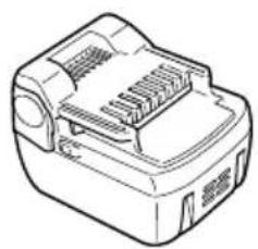
- Battery
natural_image
Line drawing of a mechanical power strip device (no text or symbols)
natural_image
Line drawing of a mechanical component with internal structure (no text or symbols)Optional accessories are subject to change without notice.
APPLICATIONS
○Drilling of brick and concrete block, etc.
○Driving and removing of machine screws, wood screws, tapping screws, etc.
○Drilling of various metals
○Drilling of various woods
BATTERY REMOVAL/INSTALLATION
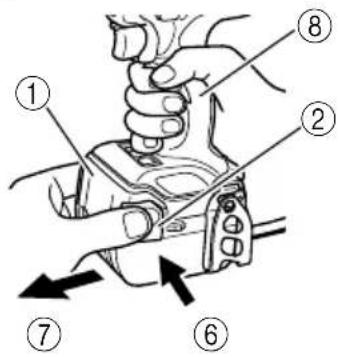
1. Battery removal
Hold the handle tightly and push the battery latch (2 pcs.) to remove the battery (see Figs. 1 and 2).
CAUTION
Never short-circuit the battery.
2. Battery installation
Insert the battery while observing its polarities (see Fig. 2).
CHARGING
Before using the impact driver drill, charge the battery as follows.
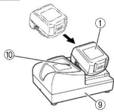
- Connect the charger's power cord to a receptacle. When the power cord is connected, the charger's pilot lamp will blink in red. (At 1-second intervals)
- Insert the battery into the charger. Firmly insert the battery into the charger until the line is visible, as shown in Fig. 3,4.
- Charging
When inserting a battery in the charger, charging will commence and the pilot lamp will light continuously in red.
When the battery becomes fully recharged, the pilot lamp will blink in red. (At 1-second intervals) (See Table 1)
(1) Pilot lamp indication
The indications of the pilot lamp will be as shown in Table 1, according to the condition of the charger or the rechargeable battery.
Table 1
| Indications of the pilot lamp | ||||
| The pilot lamp lights or blinks in red. | Before charging | Blinks | Lights for 0.5 seconds. Does not light for 0.5 seconds. (off for 0.5 seconds) | |
| While charging | Lights | Lights continuously | ||
| Charging complete | Blinks | Lights for 0.5 seconds. Does not light for 0.5 seconds. (off for 0.5 seconds) | ||
| Charging impossible | Flickers | Lights for 0.1 seconds. Does not light for 0.1 seconds. (off for 0.1 seconds) | Malfunction in the battery or the charger | |
| The pilot lamp lights in green. | Overheat standby | Lights | Lights continuously | Battery overheated. Unable to charge. (Charging will commence when battery cools) |
(2) Regarding the temperatures of the rechargeable battery
The temperatures for rechargeable batteries are as shown in Table 2, and batteries that have become hot should be cooled for a while before being recharged.
Table 2 Recharging ranges of batteries
| Rechargeable batteries | Temperatures at which the battery can be recharged |
| BSL1430, BSL1830 | 0°C - 40°C |
(3) Regarding recharging time
Depending on the combination of the charger and batteries, the charging time will become as shown in Table 3.
Table 3 Charging time (At 20°C)
| Battery\Charger | UC18YRSL |
| BSL1430, BSL1830 | Approx. 45 min. |
NOTE
The charging time may vary according to temperature and power source voltage.
-
Disconnect the charger's power cord from the receptacle
-
Hold the charger firmly and pull out the battery NOTE
After operation, pull out batteries from the charger first, and then keep the batteries properly.
How to make the batteries perform longer.
(1) Recharge the batteries before they become completely exhausted.
When you feel that the power of the tool becomes weaker, stop using the tool and recharge its battery. If you continue to use the tool and exhaust the electric current, the battery may be damaged and its life will become shorter.
(2) Avoid recharging at high temperatures.
A rechargeable battery will be hot immediately after use. If such a battery is recharged immediately after use, its internal chemical substance will deteriorate, and the battery life will be shortened. Leave the battery and recharge it after it has cooled for a while.
CAUTION
When the battery charger has been continuously used, the battery charger will be heated, thus constituting the cause of the failures. Once the charging has been completed, give 15 minutes rest until the next charging.
○If the battery is recharged when it is warm due to battery use or exposure to sunlight, the pilot lamp map light in green.
The battery will not be recharged. In such a case, let the battery cool before charging.
When the pilot lamp flickers in red (at 0.2-second intervals), check for and take out any foreign objects in the charger's battery installation hole. If there are no foreign objects, it is probable that the battery or charger is malfunctioning. Take it to your authorized Service Center.
PRIOR TO OPERATION
1. Setting up and checking the work environment
Check if the work environment is suitable by following the precautions.
HOW TO USE
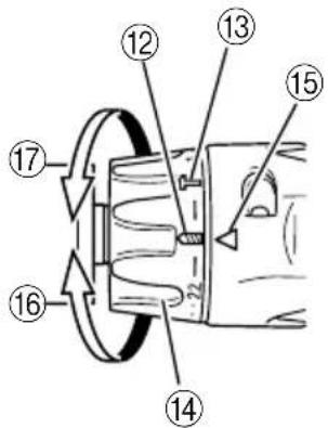
1. Confirm the cap position (see Fig. 5)
The three modes of screwdriver, drill and impact drill can be switched by the position of the cap in this unit.
(1) When using this unit as a screwdriver, line up the one of the numbers "1, 3, 5 ... 22" on the cap, or the black dots, with the triangle mark on the outer body.
(2) When using this unit as a drill, align the cap drill mark "###" with the triangle mark on the outer body.
(3) When using this unit as an impact drill, align the cap hammer mark "T" with the triangle mark on the outer body.
CAUTION
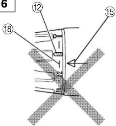
○The cap cannot be set between the numerals "1, 3, 5 ... 22" or the black dots.
○Do not use with the cap numeral between "22" and the black line at the middle of the drill mark. Doing so may cause damage (See Fig. 6).
2. Tightening torque adjustment
(1) Tightening torque
Tightening torque should correspond in its intensity to the screw diameter. When too strong torque is used, the screw head may be broken or be injured. Be sure to adjust the cap position according to the screw diameter.
(2) Tightening torque indication
The tightening torque differs depending on the type of screw and the material being tightened.
The unit indicates the tightening torque with the numbers "1, 3, 5 ... 22" on the cap, and the black dots. The tightening torque at position "1" is the weakest and the torque is strongest at the highest number (See Fig. 5).
(3) Adjusting the tightening torque
Rotate the cap and line up the numbers "1, 3, 5 ... 22" on the cap, or the black dots, with the triangle mark on the outer body. Adjust the cap in the weak or the strong torque direction according to the torque you need.
CAUTION
☐The motor rotation may be locked to cease while the unit is used as drill. While operating the impact driver drill, take care not to lock the motor.
☐Too long hammering may cause the screw broken due to excessive tightening.
3. Rotation to Impact changeover (See Fig. 5)
The "Rotation (Rotation only)" and "Impact (Impact + Rotation)" can be switched by aligning the drill mark "###" or the hammer mark "T with the triangle mark on the outer body.
○To make holes in the metal, wood or plastic, switch to "Rotation (Rotation only)".
To make holes in bricks or concrete blocks, switch to "Impact (Impact + Rotation)".
CAUTION
If an operation which is normally performed at the "Rotation" setting is performed at "Impact" setting, the effect of making holes does not only increase but it may also damage the bit or other parts.
4. Change rotation speed
Operate the shift knob to change the rotational speed. Move the shift knob in the direction of the arrow (see Figs. 7 and 8).
When the shift knob is set to "LOW", the drill rotates at a low speed.!»en set to "HIGH", the drill rotates at a high speed.
CAUTION
○When changing the rotational speed with the shift knob, confirm that the switch is off.
Changing the speed while the motor is rotating will damage the gears.
When setting the shift knob to "HIGH" (high speed) and the position of the cap is between "17" and "22", it may happen that the clutch does not engage and that the motor is locked. In such a case, please set the shift knob to "LOW" (low speed).
○If the motor is locked, immediately turn the power off. If the motor is locked for a while, the motor or battery may be burnt.
5. The scope and suggestions for uses
The usable scope for various types of work based on the mechanical structure of this unit is shown in Table 4.
Table 4
| Work Suggestions | ||
| Drilling | Brick | Use for drilling purpose. |
| Wood | ||
| Steel | ||
| Aluminum | ||
| Driving | Machine screw Use the | bit or socket matching the screw diameter. |
| Wood screw Use after drilling a pilot hole. | ||
6. How to select tightening torque and rotational speed
Table 5
| Use Cap Position | Rotating speed selection (Position of the shift knob) | |||
| LOW (Low speed) HIGH | (High speed) | |||
| Driving | Machine screw 1 | -22 | For 4 mm or smaller diameter screws. | For 6 mm or smaller diameter screws. |
| Wood screw 1 - | For 6.8 mm or smaller nominal diameter screws. | For 3.8 mm or smaller nominal diameter screws. | ||
| Drilling | Brick | For 13 mm or smaller diameters. | For 10 mm or smaller diameters. | |
| Wood | For 36 mm or smaller diameters. | For 18 mm or smaller diameters. | ||
| Metal | For drilling with a metal working drill bit. | — | ||
CAUTION
☐ The selection examples shown in Table 5 should be considered as general standard. As different types of tightening screws and different materials to be tightened are used in actual works proper adjustments are naturally necessary.
When using the impact driver drill with a machine screw at HIGH (high speed), a screw may damage or a bit may lose due to the tightening torque is too strong. Use the impact driver drill at LOW (low speed) when using a machine screw.
NOTE
The use of the Li-ion battery in a cold condition (below 0 degree Centigrade) can sometimes result in the weakened tightening torque and reduced amount of work. This, however, is a temporary phenomenon, and returns to normal when the battery warms up.
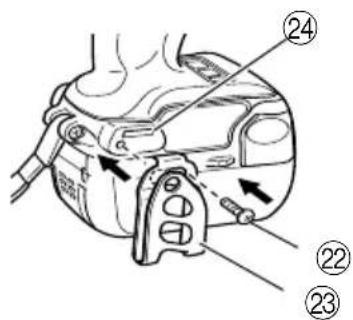
7. Using the hook
The hook is used to hang up the power tool to your waist belt while working.
CAUTION:
When using the hook, hang up the power tool firmly not to drop accidentally. If the power tool is dropped, it may lead to an accident.
When carrying the power tool with hooked to your waist belt, do not fit any bit to the tip of power tool. If the sharp bit such as drill is fitted to the power tool when carrying it with hooked to your waist belt, you will be injured.
○Install securely the hook. Unless the hook is securely installed, it may cause an injury while using.
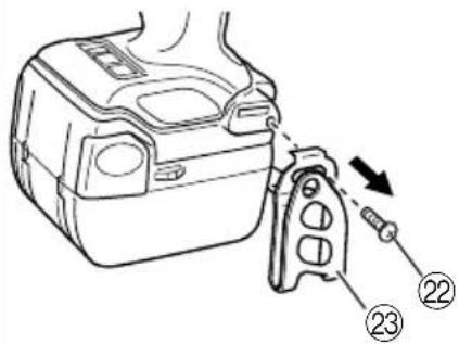
(1) Removing the hook.
Remove the screws fixing the hook with Philips screw driver. (Fig. 9)
(2) Replacing the hook and tightening the screws.
Install securely the hook in the groove of power tool and tighten the screws to fix the hook firmly. (Fig. 10)
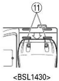
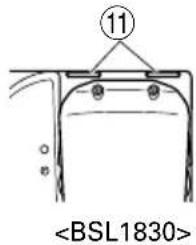
8. About Remaining Battery Indicator
When pressing the remaining battery indicator switch, the remaining battery indicator lamp lights and the battery remaining power can be checked. (Fig.11) When releasing your finger from the remaining battery indicator switch, the remaining battery indicator lamp goes off. The table 6 shows the state of remaining battery indicator lamp and the battery remaining power.
Table 6
| State of lamp | Battery Remaining Power |
| [TCWK] | The battery remaining power is enough. |
 | The battery remaining power is a half. |
 | The battery remaining power is nearly empty.Re-charge the battery soonest possible. |
As the remaining battery indicator shows somewhat differently depending on ambient temperature and battery characteristics, read it as a reference.
NOTE:
○Do not give a strong shock to the switch panel or break it. It may lead to a trouble.
To save the battery power consumption, the remaining battery indicator lamp lights while pressing the remaining battery indicator switch.
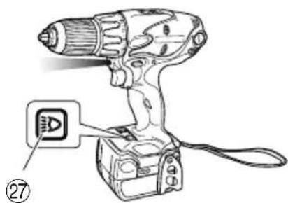
9. How to use the LED light
Every time you press the light switch on the switch panel, the LED light lights or goes off. (Fig. 12) To prevent the battery power consumption, turn off the LED light frequently.
CAUTION:
○Do not expose directly your eye to the light by looking into the light.
If your eye is continuously exposed to the light, your eye will be hurt.
NOTE:
To prevent the battery power consumption caused by forgetting to turn off the LED light, the light goes off automatically in about 15 minutes.
10. Mounting and dismounting of the bit
(1) Mounting the bit
Loosen the sleeve by turning it toward the left (in the counterclockwise direction as viewed from the front) to open the clip on the keyless chuck. After inserting a driver bit, etc., into the keyless drill chuck, and tighten the sleeve by turning it toward the right (in the clockwise direction as viewed from the front) (See Fig. 13).
○If the sleeve becomes loose during operation, tighten it further.
The tightening force becomes stronger when the sleeve is tightened additionally.
(2) Dismounting the bit
Loosen the sleeve by turning it toward the left (in the counterclockwise direction as viewed from the front), and then take out the bit, etc. (See Fig. 13).
NOTE
If the sleeve is tightened in a state where the clip of the keyless chuck is opened to a maximum limit, a click noise may occur. This is the noise that occurs when the loosening of the keyless chuck is prevented and is not a malfunction.
CAUTION
When it is no longer possible to loosen the sleeve, use a vise or similar instrument to secure the bit. Set the clutch mode between 1 and 7 and then turn the sleeve to the loose side (left side) while operating the clutch. It should be easy now to loosen the sleeve.
11. Automatic spindle-lock mechanism
This unit has automatic spindle-lock mechanism for quick bit changes.
12. Confirm that the battery is mounted correctly
13. Check the rotational direction
The bit rotates clockwise (viewed from the rear side) by pushing the R-side of the selector button. The L-side of the selector button is pushed to turn the bit counterclockwise (See Fig. 14). (The (L) and (R) marks are provided on the selector button.)
CAUTION
○Always use this unit with clockwise rotation, when using it as an impact drill.
14. Switch operation
○When the trigger switch is depressed, the tool rotates. When the trigger is released, the tool stops.
○The rotational speed of the drill can be controlled by varying the amount that the trigger switch is pulled. Speed is low when the trigger switch is pulled slightly and increases as the trigger switch is pulled more.
NOTE
○A buzzing noise is produced when the motor is about to rotate. This is only a noise, not a machine failure.
15. For drilling into brick
Excessive pressing force never increases drilling speed. It will not only damage the drill tip or reduce working efficiency, but could also shorten the service life of drill bit. Operate the impact driver drill within 10-15 kg pressing force while drilling into brick.
MAINTENANCE AND INSPECTION
1. Inspecting the tool
Since use of as dull tool will degrade efficiency and cause possible motor malfunction, sharpen or replace the tool as soon as abrasion is noted.
2. Inspecting the mounting screws
Regularly inspect all mounting screws and ensure that they are properly tightened. Should any of the screws be loose, retighten them immediately. Failure to do so could result in serious hazard.
3. Maintenance of the motor
The motor unit winding is the very "heart" of the power tool. Exercise due care to ensure the winding does not become damaged and/or wet with oil or water.
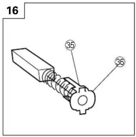
4. Inspecting the carbon brushes (Fig. 15)
The motor employs carbon brushes which are consumable parts. Since and excessively worn carbon brush can result in motor trouble, replace the carbon brush with new ones when it becomes worn to or near the “wear limit”. In addition, always keep carbon brushes clean and ensure that they slide freely within the brush holders.
NOTE
When replacing the carbon brush with a new one, be sure to use the Hitachi Carbon Brush Code No. 999054.
5. Replacing carbon brushes
Take out the carbon brush by first removing the brush cap and then hooking the protrusion of the carbon brush with a flat head screw driver, etc., as shown in Fig. 17.
When installing the carbon brush, choose the direction so that the nail of the carbon brush agrees with the contact portion outside the brush tube. Then push it in with a finger as illustrated in Fig. 18. Lastly, install the brush cap.
CAUTION
Be absolutely sure to insert the nail of the carbon brush into the contact portion outside the brush tube. (You can insert whichever one of the two nails provided.)
Caution must be exercised since any error in this operation can result in the deformed nail of the carbon brush and may cause motor trouble at an early stage.
6. Cleaning on the outside
When the Impact driver drill is stained, wipe with a soft dry cloth or a cloth moistened with soapy water. Do not use chloric solvents, gasoline or paint thinner, for they melt plastics.
7. Storage
Store the Impact driver drill in a place in which the temperature is less than 40^ C and out of reach of children.
8. Service parts list
CAUTION
Repair, modification and inspection of Hitachi Power Tools must be carried out by a Hitachi Authorized Service Center.
This Parts List will be helpful if presented with the tool to the Hitachi Authorized Service Center when requesting repair or other maintenance.
In the operation and maintenance of power tools, the safety regulations and standards prescribed in each country must be observed.
MODIFICATIONS
Hitachi Power Tools are constantly being improved and modified to incorporate the latest technological advancements.
Accordingly, some parts may be changed without prior notice.
NOTE
Due to HITACHI's continuing program of research and development, the specifications herein are subject to change without prior notice.
일반적인 안전 수칙
경고!
설명서를 자세히 읽으십시오.
natural_image
Line drawing of a mechanical power bank with internal slots and housing (no text or symbols)(BSL1430)

natural_image
Line drawing of a mechanical device with ports and casing (no text or symbols)(BSL1830)
natural_image
Line drawing of a quill pen with inkwell, no text or symbols present
natural_image
Line drawing of a quill pen with inkwell, no text or symbols present
natural_image
Line drawing of a quill pen with inkwell, no text or symbols present
Hitachi Koki Co., Ltd.

- Cordless Impact Driver Drill
- 충전 임팩트 드라이버 드릴
- DV 14DSL · DV 18DSL
- Read all instructions
- SAVE THESE INSTRUCTIONS
- 1) Work area safety
- 2) Electrical safety
- 3) Personal safety
- 4) Power tool use and care
- 5) Battery tool use and care
- PRECAUTION
- PRECAUTIONS FOR CORDLESS IMPACT DRIVER DRILL
- CAUTION:
- CAUTION ON LITHIUM-ION BATTERY
- WARNING
- SPECIFICATIONS
- CAUTION
- OPTIONAL ACCESSORIES (sold separately)
- APPLICATIONS
- BATTERY REMOVAL/INSTALLATION
- Battery removal
- Battery installation
- CHARGING
- NOTE
- How to make the batteries perform longer.
- PRIOR TO OPERATION
- Setting up and checking the work environment
- HOW TO USE
- Confirm the cap position (see Fig. 5)
- Tightening torque adjustment
- Rotation to Impact changeover (See Fig. 5)
- Change rotation speed
- The scope and suggestions for uses
- How to select tightening torque and rotational speed
- Using the hook
- About Remaining Battery Indicator
- NOTE:
- How to use the LED light
- Mounting and dismounting of the bit
- Automatic spindle-lock mechanism
- Confirm that the battery is mounted correctly
- Check the rotational direction
- Switch operation
- For drilling into brick
- MAINTENANCE AND INSPECTION
- Inspecting the tool
- Inspecting the mounting screws
- Maintenance of the motor
- Inspecting the carbon brushes (Fig. 15)
- Replacing carbon brushes
- Cleaning on the outside
- Storage
- Service parts list
- MODIFICATIONS
- 일반적인 안전 수칙
- 경고!
- Hitachi Koki Co., Ltd.
Brand : HiKOKI
Model : DV14DSL
Category : Drill