
FZRR 5650-A - Robotic mower Fieldmann - Free user manual and instructions
Find the device manual for free FZRR 5650-A Fieldmann in PDF.

| Product Type | Robotic Lawn Mower |
| Model | FZRR 5650-A |
| Brand | Fieldmann |
| Dimensions (L x W x H) | 55 x 38 x 25 cm |
| Weight | 9.5 kg |
| Power Source | 18V Li-ion battery |
| Battery Capacity | 4.0 Ah |
| Charging Time | 60 minutes |
| Working Time | 70 minutes |
| Cutting Width | 25 cm |
| Cutting Height Range | 20 - 60 mm |
| Number of Blades | 3 |
| Maximum Slope | 25° |
| Maximum Lawn Area | 1500 m² |
| Rain Sensor | Yes |
| Perimeter Wire Required | Yes (included) |
| Mowing Pattern | Systematic (random + grid) |
| Noise Level | 65 dB(A) |
| Security Lock | PIN code |
| Lift-Up Sensor | Yes |
| App Control | No |
| Included Accessories | Charging station, perimeter wire, pegs, manual |
| Warranty | 2 years |
Frequently Asked Questions - FZRR 5650-A Fieldmann
User questions about FZRR 5650-A Fieldmann
0 question about this device. Answer the ones you know or ask your own.
Ask a new question about this device
Download the instructions for your Robotic mower in PDF format for free! Find your manual FZRR 5650-A - Fieldmann and take your electronic device back in hand. On this page are published all the documents necessary for the use of your device. FZRR 5650-A by Fieldmann.
USER MANUAL FZRR 5650-A Fieldmann
natural_image
Technical line drawing of a robotic car with visible motors and housing (no text or symbols)FZRR 5650-A, FZRR 5950-A
English 3-30
Češťina 31-58
Slovenšina....59-86
Magyarul 87-114
Polski 115-142
Robotic Lawn Mower USER MANUAL
Thank you for purchasing this robotic lawn mower from FIELDMANN. Before using it, please read this user manual carefully and keep it for future reference.
TABLE OF CONTENTS
-
IMPORTANT SAFETY INSTRUCTIONS....5
For domestic use only....5 -
INTRODUCTION....8
List of Parts 8
Package Contents 9
Functions....9
- PLANNING....10
Planning the Laying of the Perimeter Wire....10
Types of Lawns....11
Lawn Type with Main Zone Only....11
Lawn Type with Main Zone and Subzones....11
Lawn Type with Separate Zones....12
Choosing the Location for the Charging Base....12
- INSTALLATION 13
Preparation....13
Installing and Connecting the Charging Base....13
Battery Charging....14
Installation of the Perimeter Wire....14
Connecting the Perimeter Wire....17
Checking Perimeter Wire....17
First Start....18
Test Parking in the Charging Base....18
- CONTROL PANEL....19
Operation Selection 19
Buttons with Multiple Functions....19
- MENU FUNCTIONS AND HOW TO SET THEM UP....20
Main Menu 20
Structure of Menus....20
Timer 21
Division into Zones 21
Settings....22
Security 22
- USAGE 23
Charging a Discharged Battery (See the "Battery Charging" section)....23
Starting....23
Stopping....24
Switching Off 24
Cutting Height Adjustment....24
- MAINTENANCE 25
Winter Storage 25
After Winter Storage 25
Cleaning 25
Transportation and Disposal 26
During Storms 26
Blade Replacement....26
Battery Replacement....26
- TROUBLESHOOTING....27
Error Codes 27
Symptoms....28 - TECHNICAL SPECIFICATIONS....29
- DISPOSAL....30
1. IMPORTANT SAFETY INSTRUCTIONS

IMPORTANT: READ THE ENTIRE USER MANUAL. KEEP THIS USER MANUAL FOR FUTURE REFERENCE.

WARNING:
When using electrical devices, always follow safety instructions to reduce the risk of fire, electric shock, and other serious injuries.
Carefully read this user manual. Thoroughly familiarise yourself with the controls and the correct use of this machine. Learn the machine's functions and how to quickly turn it off.
Never allow children to use this lawn mower. Never allow adults to use lawn mower without proper training.
Do not allow children or pets near the robotic lawn mower while it is in operation.
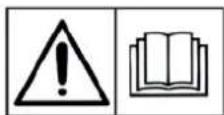
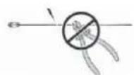
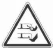
Read the user manual.
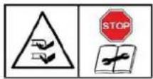
Risk of finger and toe amputation. Keep hands and feet away from rotating parts.
Warning - Before starting or lifting the machine, the blocking device must be engaged.

Risk of finger and toe amputation. Keep hands and feet away from rotating parts.
Do not ride on the lawn mower, and never ride children or pets on it.
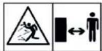
When mowing the grass, keep the lawn mower on the ground at all times. Tilting or lifting may cause stones to fly. Keep others at a safe distance (5 m).

Warning: After switching off the robotic lawn mower, wait until the cutting blades come to a complete stop.

Protection class III.

Conformity mark – Conformity with all relevant European standards.
Switch mode power supply unit

Isolating transformer with protection against

For use in dry rooms only.

Protection class II (double-insulated)
FOR DOMESTIC USE ONLY
PERSONAL SAFETY
- Use this lawn mower only for cutting grass and lawns according to the instructions provided in this user manual. Before use, familiarize yourself with all controls and the proper use of the machine.
- Ensure that the automatic perimeter delineation system is properly installed before use.
• Always keep the lawn mower out of reach of children and pets.
- Never use the lawn mower unsupervised when other people, especially children, are nearby.
- When working with the robotic lawn mower, be cautious, pay attention to the work and use common sense.
- Do not use the lawn mower if you are tired, ill or under the influence of drugs, medication or alcohol. This can result in a serious injury.
- Wear personal protective equipment, such as safety glasses, slip-resistant shoes, work gloves, to prevent potential injury.
- Do not operate the lawn mower barefoot or in open-toed shoes.
- Wear appropriate clothing. Do not wear loose clothing or jewellery when working, and keep your hair, clothing and gloves at a safe distance from moving parts.
- Do not use the lawn mower on steep slopes.
- Never touch the rotating blade.
- Do not use the lawn mower on gravel. There is a risk of injury from fl ying stones.
• Before starting grass cutting, inspect the mowed area and remove all objects that could be caught or thrown by the lawn mower, such as stones or branches.
- If possible, avoid operating the lawn mower on wet grass.
- Remove all animal droppings before mowing the grass.
• Before each use, visually inspect the cutting blades and their fastening elements for signs of damage. Replace any worn or damaged parts to prevent imbalance.
- Do not use the lawn mower if it is not complete or if any unauthorised modifications have been made to it. Always keep your body, especially your hands and feet, at a safe distance from the cutting blade.
- Warning: After switching off the motor, the cutting blade continues to rotate for a certain period of time.
- Before starting the following activities, ensure that the cutting blade has completely stopped:
- removing blockages,
- adjusting cutting height,
- lifting or transporting the lawn mower,
- tilting the lawn mower,
- checking or cleaning the lawn mower,
- performing maintenance.
• If the robotic lawn mower starts to vibrate strongly, switch off the motor immediately, wait until it stops and determine the cause.
- The operator or user is responsible for injuries or dangers to other persons or their property.
- This device may be only used by children aged 8 years and older and persons with reduced physical, sensory, or mental capabilities or lack of experience and knowledge, provided they are supervised or have been instructed on the safe use of the device and understand the potential dangers. Children must not play with the device. Cleaning and maintenance performed by the user must not be performed by unsupervised children. Do not modify the lawn mower in any way.
- We recommend programming the robotic lawn mower to operate when no activities are taking place in the mowed area, such as at night. However, keep in mind that some animals, such as hedgehogs and moles, are active at night. These animals may be injured by the robotic lawn mower.
- Do not place any objects on the lawn mower or the charging base.
- Do not use the lawn mower if the protective cover, cutting blade disc, or the mower body is damaged. Do not use it if the cutting blades, nuts or cables are damaged. Never connect a damaged cable. Do not touch a damaged cable before disconnecting it from the power source.
- Do not use the lawn mower if the STOP button is malfunctioning.
• Always switch off the lawn mower when it is not in use. The lawn mower can only be started after entering the correct PIN code.
- Do not use the lawn mower when the irrigation system is active. Use the timer function to set the lawn mower's operation so that it never works simultaneously with irrigation. Do not wash the lawn mower with a strong stream of water and do not immerse it partially or completely in water, as it is not waterproof.
- Metal objects in the ground (e.g. buried electrical cables) can cause the lawn mower to stop. Metal objects can interfere with the signal of the perimeter wire, which can cause the lawn mower to stop.
- Keep in mind that pets can burrow and damage the perimeter wire, so check it regularly.
- The manufacturer does not guarantee full compatibility between the lawn mower and other types of wireless systems, such as remote controls, radio transmitters, hearing aids, ground-based animal fences, etc.
ELECTRICAL SAFETY
- Do not operate the lawn mower in explosive environments, such as the presence of flammable liquids, gases, or dust. Lawnmowers may sometimes cause sparking, which can ignite dust or flammable fumes.
- Ensure that the connection to the electrical network is made in accordance with the laws applicable to the area. For the safety of the electrical distribution connected to the power source, this distribution must be equipped with a properly functioning grounding circuit. The supplied circuit must be protected by a residual current device (RCD) with an activation current not exceeding 30 mA.
- If the power cable is damaged during use, press the "STOP" button to stop the lawn mower and pull the power cable plug out of the socket.
- Keep extension cords at a safe distance from moving hazardous parts to prevent damage to the cords, which can lead to contact with live parts.
- Avoid contact of your body or body parts with grounded surfaces, such as pipes. If your body is grounded, there is an increased risk of electric shock.
- Procedure in case of storm: In case of a storm threat, it is recommended to disconnect the charging base from the power to reduce the risk of damage to lawn mower components.
- Never touch the charging base with wet hands.
- Check the power cables and charging base cables regularly for signs of damage or wear.
- Do not expose the lawn mower to temperatures above 80 °C, which can be reached, for example, by prolonged exposure to direct sunlight or by leaving the lawn mower in the hot boot of a passenger car.
BATTERY SAFETY
• The lawn mower contains lithium-ion batteries. Do not expose these batteries to open flames or high temperatures as there is a risk of explosion.
- Batteries can become hot under high loads or high temperatures. Allow the lawn mower to cool down for 30 minutes before recharging.
- The operating and storage temperature range is 0–50 °C / 32–122 °F. The charging temperature range is 0–45 °C / 32–113 °F. Excessively high temperatures may cause damage to the product.
- Use only the charger and power supply provided by the supplier. Using the wrong charger can cause electric shock, overheating or leakage of corrosive liquids from the battery. In case of electrolyte leakage, flush with water / neutralising agent; in case of eye contact, seek medical assistance.
- The lawn mower must be powered only with a safe low voltage, see technical specifications.
MAINTENANCE
- Check the proper tightening of all accessible screws and nuts, especially on the cutting blade disc.
- Check and clean the lawn mower and its charging base regularly to remove grass debris and obstacles. Note that some garden creatures, such as spiders, insects, snails, and slugs, may inhabit the slots of the lawn mower. These creatures may attract smaller animals, such as rodents, which can damage the lawn mower if not deterred.
• Before each use and after any collision, inspect the lawn mower for signs of wear or damage; if damaged, arrange for the necessary repair or replacement of parts.
• Use only original spare parts and replacement cutting blades. This will ensure that you maintain the safety of your lawn mower. - Do not attempt to repair the lawn mower or its parts unless you are qualified to do so.
TRANSPORT
When transporting the robotic lawn mower over a long distance, use its original packaging.
Safe transport within the work area and over short distances outside the work area:
- Press the STOP button to stop the robotic lawn mower.
- Switch off the robotic lawn mower.
- Grasp the robotic lawn mower by the handle at the rear of the robotic lawn mower. Carry the robotic lawn mower with the blade pointing away from the body.
IMPORTANT INFORMATION
Do not lift the robotic lawn mower when it is parked in the charging base. This could cause damage to the charging base or the robotic lawn mower.
Disconnect the robotic lawn mower from the charging base before lifting it.

MAINTENANCE
- Check the robotic lawn mower once a week and replace any damaged or worn parts.
- In particular, check that the blades and the blade disc are not damaged. Also, check that the blades are securely fastened. If necessary, replace all blades at the same time to maintain the balance of the rotating parts. See the Blade Replacement section.
IMPORTANT INFORMATION
Never use a pressure washer or running water to clean the robotic lawn mower.
Never use solvents for cleaning.
2. INTRODUCTION
This section provides important information to be considered during the installation planning.
The robotic lawn mower system comprises four main components:
- Robotic lawn mower: It mows lawn in an essentially random pattern. The robotic lawn mower is powered by a maintenance-free battery.
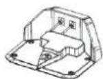
- Charging base: The lawn mower returns to this base when its battery level is too low.
The charging base has 2 functions:
- It sends control signals to the perimeter wire so that the robotic lawn mower detects its working area or finds the charging base.
- It charges the battery of the robotic lawn mower.
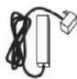
• Power adapter for the base: Plugged into a 100–240 V electrical socket, connected via a 6 m long low-voltage output cable.
The low-voltage output cable must not be shortened or lengthened.
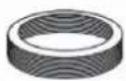
Perimeter wire for defining the mowed area. The length of the included cable varies by model.
(FZRR 5650-A:150M; FZRR 5950-A:200M).
The maximum permissible length of the perimeter wire is 300 m.
LIST OF PARTS
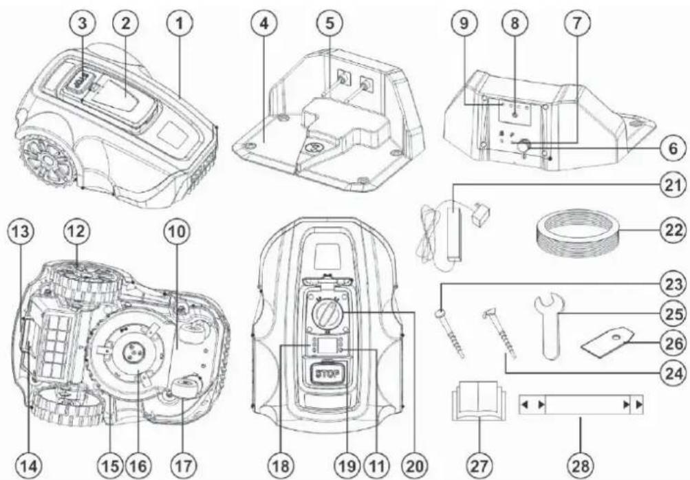

The numbers in the figure indicate the following parts:
- Lawn mower body
- Control panel cover
- STOP button
- Charging base
- Charging contacts
- Base electrical socket
- Connectors for the perimeter wire
- Two-colour LED indicator
- Charging base label
- Chassis box containing electronics, battery and motors
- Power switch
- Rear wheel
- Transport handle
-
Battery cover
-
Blade disc guard
- Blade disc
- Front wheel
- Control panel
- Rain sensor
- Cutting height adjustment control
- Power adapter
- Perimeter wire
- Charging base anchor stake
- Perimeter wire anchor stakes
- Spanner
- Spare blade
- User Manual
- Wire laying gauge (provided separately, outside the box)
PACKAGE CONTENTS
The robotic lawn mower package contains the following items.
| FZRR 5650-A FZRR 5950-A | ||
| Robotic lawn mower | √ | √ |
| Charging base √ | √ | |
| Power adapter √ | √ | |
| Perimeter wire 150 m 200 m | ||
| Nails for the charging base 4 pcs 4 pcs | ||
| Stakes 150 pcs 200 pcs | ||
| Flat spanner | √ | √ |
| User manual | √ | √ |
| Spare blade 3 pcs 3 pcs | ||
| Wire gauge √ | √ |
FUNCTIONS
Working Area
The robotic lawn mower is recommended for use on lawns with a maximum area as specified in the Technical Specifications section.
The efficiency of the robotic lawn mower depends on the condition of its blades, as well as the type, height, and moisture level of the grass. The garden layout is also important. The robotic lawn mower can cover more area in an hour if the garden consists mostly of open lawns compared to gardens with small lawns separated by trees, flower beds, and pathways.
A fully charged robotic lawn mower can run for 60 to 120 minutes, depending on the battery capacity, its age and the density of the grass. Afterwards, the lawnmower will recharge for 90 to 150 minutes. Charging times may vary depending on, among other things, the ambient temperature.
Cutting Technique
The cutting system of the robotic lawn mower is based on an efficient and energy-saving principle.
Equipped with a patented cutting system, the lawn mower produces small grass clippings that quickly decompose and serve as fertiliser.
To achieve the best results, it is recommended to let the lawn mower operate mainly in dry weather.
The lawn mower can cut in the rain or high humidity, but wet grass may stick to the lawnmower, and there is an increased risk of slippage on steeper slopes.
In the event of a storm, disconnect the power adapter from the power source and the perimeter wire from the charging base.
To maintain optimal cutting results, keep the blades in good condition. It is important to keep the lawn free of branches, small stones and other objects for the blades to remain sharp.
Regularly replace the blades to get the best results. Replacing blades is very easy. See "Blade Replacement" on page 26.
Operating Mode
The robotic lawn mower cuts the lawn automatically. It alternates between charging and cutting phases.
When the battery level is too low, the lawn mower starts searching for the charging base.
If you leave the rain sensor in the factory setting, i.e. Enabled (switched on), the robotic lawn mower will start searching for the charging base. Mowing will resume several hours after the rain stops.
When searching for the charging base, the lawn mower does not cut immediately but searches for the perimeter wire in an irregular motion. It then follows the perimeter wire clockwise, locates the charging base, parks in it and the battery begins to charge.
Once ready for the next task, the lawn mower leaves the charging base automatically and resumes operation.
The control panel under the cover on the top of the robotic lawn mower is where you can change all the settings of the robotic lawn mower.
Opening the control panel cover while the lawn mower is operating stops it instantly. However, it's recommended to press the STOP button before opening the control panel cover.
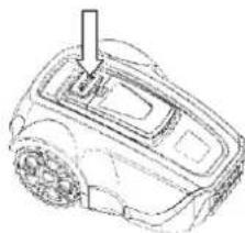
The STOP button on the top of the robotic lawn mower is mainly used to stop the robotic lawn mower when it is running.
IMPORTANT INFORMATION
You can stop the robotic lawn mower at any time by pressing the STOP button.

natural_image
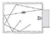
Line drawing of a robotic device with a handle and gear mechanism (no text or symbols)Movement Pattern
The movement pattern of the robotic lawn mower is irregular and is determined by the robotic lawn mower itself. The pattern of movement never repeats.
Thanks to the cutting system, the lawn is evenly mowed without traces of the lawn mower's movement.
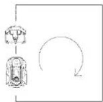
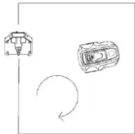
Search Method
The robotic mower moves irregularly until it finds the perimeter wire. It then follows the perimeter wire clockwise to the charging base and parks properly into it.
flowchart
graph TD
    A["Step 1"] --> B["Step 2"]
    B --> C["Step 3"]
    C --> D["Feedback Loop"]
    D --> A
3. PLANNING
The layout and texture of each lawn is different, so we recommend that you familiarise yourself with the set-up process before installing your robotic lawn mower. Planning will be more straightforward if you create a layout sketch of the working area, including all obstacles. This will make it easier for you to choose the ideal position for the charging base and for laying the perimeter wire.
PLANNING THE LAYING OF THE PERIMETER WIRE
The perimeter wire acts as an "invisible wall" for the robotic lawn mower. It defines the boundaries of the lawn zones and encloses specific areas where the robotic lawn mower should not enter.
The perimeter wire is secured to the ground with the stakes supplied with the robotic lawn mower. Soon after laying, the wire with the stakes will become overgrown and will not be visible.
Once the lawn mower starts, it emits a signal through the perimeter wire. This signal keeps the robotic lawn mower within its working zones and outside the pre-defined restricted areas.
Objects within the Lawn
- Objects such as flower beds, small trees, ponds or large trees with raised roots can be protected by setting up "perimeter islands".
- Vertical, relatively firm obstacles higher than 15 cm, such as trees, telephone or electrical poles, or a pool, don't need specific boundary settings. The robotic lawn mower automatically turns around when it encounters these obstacles. For gentle and quiet operation, create perimeter islands around these objects.
- If the obstacle areas are close together, it is better to confi ne them within a single continuous perimeter island.
For more details on how to create perimeter islands, see the section "Boundaries within the Working Area" on page 16.
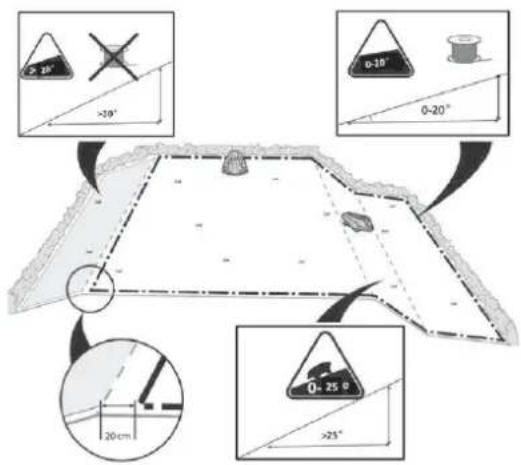
Slopes
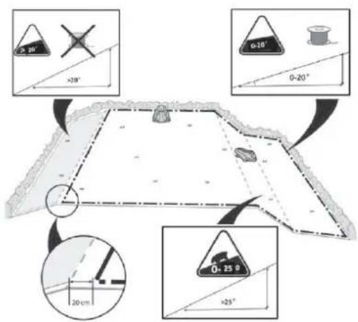
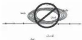
The perimeter wire can be laid across slopes with an incline of less than 20^ .

The perimeter wire should not be laid across slopes steeper than 20^ . The robotic lawn mower may have problems with turning. The lawn mower might then stop, beep, and display Error 8 message. The risk is higher in wet conditions when the wheels may slip on wet grass.
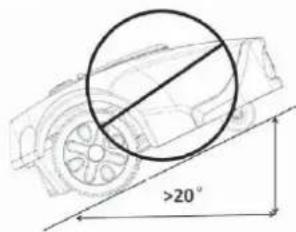
However, the perimeter wire can be laid across slopes steeper than 20^ if there is an obstacle, such as a fence or dense hedge, where the lawn mower could collide.
The robotic lawn mower can handle lawns with a slope of up to 25^ inside the working area. Areas with steeper slopes should be separated by a perimeter wire.
If the outer edge of the working area is inclined by more than 20^ , the perimeter wire must be laid on the plane before the start of the slope at a distance of about 20 cm from its edge.
The robotic lawn mower handles uneven lawns well. However, fill deeper holes with soil to prevent the lawn mower from getting stuck.
TYPES OF LAWNS
What does your lawn look like?
There are three basic types of lawns, and some lawns are a combination of more than one type. Your first task is to determine which type of lawn you have.
- Main Zone Only:
The robotic lawn mower mows the entire lawn within the defined boundaries.
- Main Zone + Subzones
The robotic lawn mower can move automatically between the main zone and subzones.
- Separate Zone
The robotic lawn mower will mow each zone separately, and manual transfer is needed between zones.

LAWN TYPE WITH MAIN ZONE ONLY
A 'Main Zone Only' lawn consists of one continuous area. It does not include any subzones or separate zones. The entire lawn area forms one continuous zone and all areas of the lawn are wide enough (at least 1 metre wide at the narrowest point) for the robotic lawn mower to navigate.

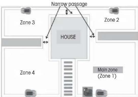
LAWN TYPE WITH MAIN ZONE AND SUBZONES
This type of lawn comprises multiple zones connected by narrow passages. These passages can be relatively narrow but wide enough (40–50 cm) for the lawn mower to pass through. The passages should be fl rm, fl at, and smooth (not rocky, sandy, or elevated).
On this type of lawn, the robotic lawn mower will be able to move from one zone to another and mow the entire area.

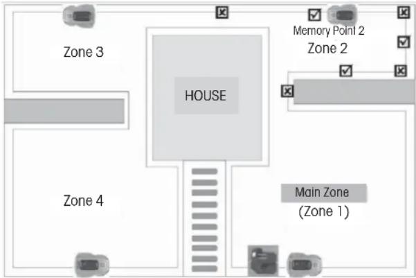
If the lawn is large, we recommend dividing it into subzones. This increases the lawn mower's efficiency, allowing you to schedule mowing for various areas at different times. A maximum of 4 zones can be defined (main zone + 3 subzones).
When setting the zone division in the main menu, the main zone is preset as zone 1. The user can add additional subzones from zone 2, zone 3, up to zone 4.
For more details, see the section "Division into Zones" on page 21.
flowchart
graph TD
    A["Main zone (Zone 1)"] --> B["HOUSE"]
    C["Zone 2"] --> B
    D["Zone 3"] --> B
    E["Zone 4"] --> B
    F["Narrow passage"] --> B
    B --> G["Floor layout with multiple rooms"]
LAWN TYPE WITH SEPARATE ZONES
This lawn type consists of two or more zones that are not interconnected.
The robotic lawn mower cannot move automatically between these zones if:
- Parts of the lawn are separated by fences, pavement or other objects that the robotic lawn mower cannot cross.
- Parts of the lawn are separated by gravel or similar material that can damage the cutting blades.
- The lawn zones are connected by passages too narrow for the lawn mower to navigate: width less than 40 cm.
- The lawn zones are located at lower or higher levels.
Separate zone that can be mowed at one go
If possible, the wire for the separated zone can be connected to the perimeter wire of the main zone.

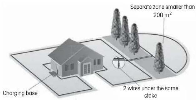
Separate zone that cannot be mowed at one go
- This large separate zone requires a separate mower operation.
- An additional charging base and power adapter (optional accessories) should be installed in this area.

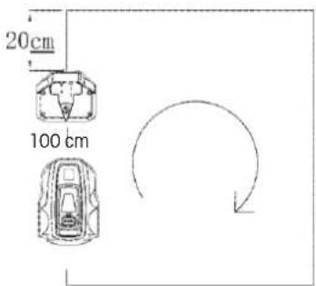
CHOOSING THE LOCATION FOR THE CHARGING BASE
The charging base should be places at the perimeter wire.
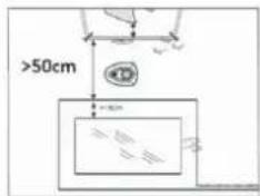
This is where the loop of the perimeter wire begins and ends. Please observe the following guidelines when choosing the best location:
- Place the charging base at least 20 cm from the corner of the perimeter wire.
- A straight line of more than 100 cm must be in front of the base for the mower to enter correctly.
- The charging base should be placed close enough to an electrical socket.
- If the lawn has multiple zones, install the charging base in the largest zone.
- Preferably, choose a shaded location for the charging base. This extends the lifespan of the battery.
- Place the charging base on a relatively flat surface. Do not place it on a slope.
- Do not place the charging base in a depressed position where it might accumulate water, potentially causing damage to the base or the lawn mower.
- Place the charging base well away from the sprinkler heads.
- Do not place the charging base in a location with magnetic interference.
4. INSTALLATION
Before starting the installation, thoroughly study this entire chapter. The installation process influences the performance of the robotic lawn mower. Therefore, careful planning of the installation is essential.
PREPARATION
- If the grass in the working area is higher than 7 cm, mow it using a standard lawn mower and collect the cut grass.
- Before installation, carefully read all the steps.
-
Make sure you have all the parts needed for the installation. The numbers in brackets refer to the image "List of Parts" on page 8.
-
lawn mower body (1)
- charging base (4)
• perimeter wire (22)
• power adapter (21)
• pin (24) - charging contacts (5)
- flat spanner (25)
• nail for the charging base (23) - gauge (28)
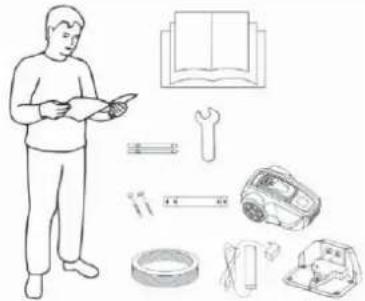
natural_image
Illustration of a person reading a book with tools and equipment nearby (no text or symbols)During installation, you will also need the following tools:
- hammer / plastic mallet (for easier driving of stakes into the ground).
• combination pliers for cutting the perimeter wire. - edge aligner / straight spade, if burying the perimeter wire is necessary.
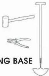
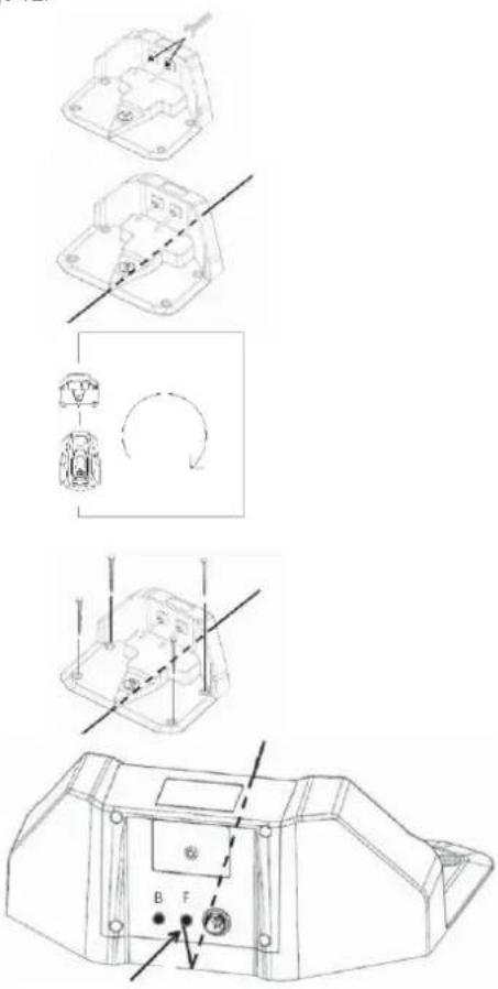
INSTALLING AND CONNECTING THE CHARGING BASE
Mounting the Charging Base
After selecting a suitable location for the charging base, see "Choosing the Location for the Charging Base" on page 12.
- Using the supplied spanner, screw the two supplied charging contacts onto the charging base.
- Secure the perimeter wire in the groove on the bottom plate of the charging base.
- Determine the direction of the charging base.
The charging base should be oriented so that the robotic lawn mower can approach it along the perimeter wire clockwise and park correctly.
-
Attach the charging base to the ground using the supplied nails. Make sure that the nail heads do not protrude.
-
Connect the end of the perimeter wire at the front of the charging base to the right connector marked with the symbol "F".
Power Adapter Connection
Connect the power cord of the power adapter to a 100-240 V power socket.
Consider the following factors when planning the placement of the power adapter:
• Proximity of the charging base
• Protection against rain
• Protection against direct sunlight
The low-voltage output cable of the power adapter is 4 metres long. It is forbidden to shorten or lengthen it.
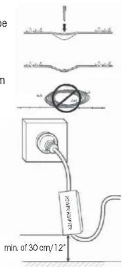
The low-voltage output cable must be laid on the ground and secured with stakes. The distance between the cable and the ground should be less than 1 cm to allow the robotic lawn mower to pass over it.
Never coil or place the low-voltage output cable in a spool or under the baseplate of the charging base, as it could interfere with signals from the charging base.
When connecting the power adapter to a wall socket, it is recommended to use a grounded circuit breaker.
When the power adapter is plugged directly into a wall socket, it must be at least 30 cm above the ground (to prevent contact with water).
Placing the power adapter on the ground is not allowed.
IMPORTANT INFORMATION
Under no circumstances should the low-voltage output cable be shortened or lengthened.
IMPORTANT INFORMATION
Position the low-voltage output cable so that the cutting disc can never come into contact with it.
IMPORTANT INFORMATION
Before cleaning or repairing the perimeter wire, pull out the plug to disconnect the charging base.
Charging Base Connection
Connect the low-voltage output cable to the charging base.
IMPORTANT INFORMATION
Creating new baseplate holes is not allowed. Use only the existing holes to secure the baseplate to the ground.
IMPORTANT INFORMATION
Do not step or walk on the baseplate of the charging base.

natural_image
Technical line drawing of a mechanical component with no visible text or symbols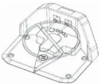
natural_image
Technical line drawing of a mechanical housing or enclosure with internal components and mounting holes (no text or symbols)BATTERY CHARGING
Once the charging base is connected, the robotic lawn mower can be charged.
Position the robotic lawn mower correctly into the charging base so that the charging contacts are connected to the input contacts of the robotic lawn mower.
To verify the correct connection:
Open the control panel cover, press the power switch and check that the lightning bolt symbol next to the battery symbol (☐) is blinking. If yes, the connection is correct. If the lightning bolt symbol does not display, the connection is not correct. When the battery is fully charged, the full battery symbol (☐) is displayed.

natural_image
Line drawing of a robotic car with visible wheels and structural components (no text or symbols)Place the robotic lawn mower into the charging base to charge the battery while laying the perimeter wire.
If the battery is discharged, it will take approximately 60–120 minutes for a complete charge.
IMPORTANT INFORMATION
The robotic lawn mower cannot be used until the installation is complete.
INSTALLATION OF THE PERIMETER WIRE
Before starting the laying of the perimeter wire, it is recommended to mow the grass in the areas where it will be placed. It will then be easier to attach the wire to the ground. This reduces the risk of the robotic lawn mower damaging the wire during operation.
The perimeter wire can be installed in one of the following ways:
- Securing the wire to the ground with stakes.
If you plan to adjust the position of the perimeter wire after a few weeks of operation, it is advantageous to secure the wire using stakes. After a few weeks, the grass will grow over the wire, making it less visible. Use a hammer / plastic mallet and the supplied stakes for installation.
- Burying the wire.
To facilitate verticutting or lawn aeration, it is better to bury the perimeter wire. If needed, both methods can be combined: secure one part of the perimeter wire using stakes and bury the other part. Use an edge aligner or straight spade for burying. The perimeter wire must be laid a minimum of 1 cm and a maximum of 5 cm deep in the ground.
Best Position of the Perimeter Wire
The perimeter wire must be laid to ensure:
- The creation of a closed loop around the working area of the robotic lawn mower. Only the original perimeter wire must be used. It is specially designed to resist moisture from the soil, which could otherwise easily damage the conductors.
- The total length of the perimeter wire must not exceed 300 metres.
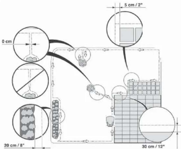
Depending on what the working area is adjacent to, the perimeter wire must be laid at different distances from obstacles. The figure below shows how the perimeter wire must be laid around the working area and around obstacles. Use the supplied gauge to determine the correct distances (see "List of Parts" on page 8).

Working Area Boundaries
If a high obstacle, such as a wall or fence, encloses the working area, the perimeter wire should be placed 30 cm from the obstacle. This prevents collisions between the robotic lawn mower and the obstacle and reduces wear on its body.
An approximately 20 cm wide area around a solid obstacle will not be mowed.
If the working area borders a small trench, such as a flower bed or a small elevation, or a low kerb (3–5 cm), the perimeter wire should be laid 20 cm inside the working area. This prevents wheels from running into the trench or onto the kerb.
An approximately 12 cm wide area along the trench/kerb will not be mowed.
If the working area borders a paved or similar surface that is at lawn level, the robotic lawn mower can be allowed to run partially over it. The perimeter wire should then be laid 5 cm from the edge of the paved area.
All grass along the pavement will be cut.
If the working area is divided by a paved area that is at lawn level, it is possible to let the robotic lawn mower run over it. It may be advantageous to store the perimeter wire under the tiles. The perimeter wire can also be laid in the joints between the tiles. Make sure that the tiles are level with the lawn to avoid excessive wear on the robotic lawn mower.
Note: The robotic lawn mower should never run over gravel, mulch or similar material that could damage its blades.

IMPORTANT INFORMATION
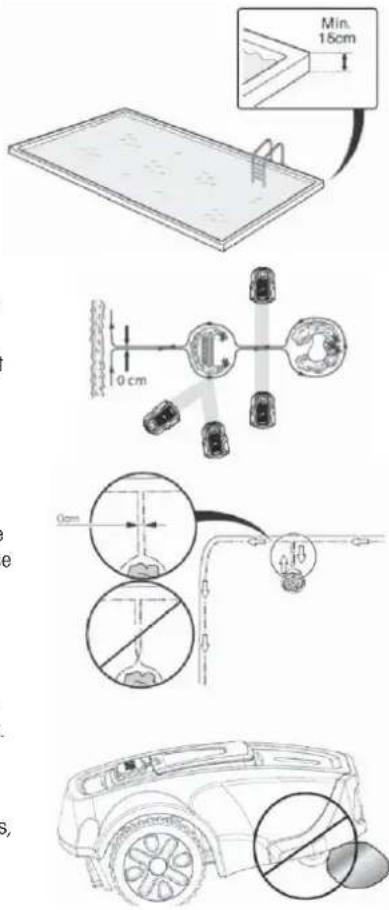
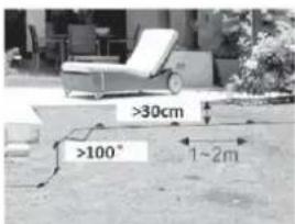
If the working area is adjacent to water bodies, slopes, precipices or public roads, the perimeter wire should be supplemented with a kerb or something similar. The height must be at least 15 cm. This ensures that the robotic lawn mower never leaves the working area under any circumstances.
Boundaries within the Working Area
Use perimeter wire to delineate areas within the working area by creating perimeter islands around obstacles that are not collision resistant, such as flower beds, shrubs, fountains, etc.
Obstacles that resist collisions, such as trees, telephone or electrical poles, or a pool with a wall higher than 15 cm, do not need to be defined by perimeter wire.
The robotic lawn mower automatically turns when it encounters these obstacles.
Lay the wire towards the area to be delimited and around it, then return it the same way. If using stakes, the wire should be laid on the return path under the same stakes. When the sections of perimeter wire leading to and from the island are close together, the robotic lawn mower can cross them.
However, the perimeter wires must not intersect on the path to and from the island.
Obstacles with a slight slope, such as stones or large trees with raised roots, must be separated by an island or removed. Otherwise, the robotic lawn mower may slip on this type of obstacle, leading to blade damage or the mower getting stuck.
Mowing Passages
Long and narrow passages and areas narrower than 50–70 cm should be avoided. When the robotic lawn mower mows, there is a risk that it will spend too much time in such areas. This may result in excessive wear on the lawn.
Laying the Perimeter Wire
To secure the perimeter wire using stakes:
- Mow the grass very short with a standard lawnmower or trimmer and place the wire close to the ground to reduce the risk of the robotic lawnmower cutting the wire or damaging its insulation.
- Lay the perimeter wire just above the ground, ensuring that the distance between it and the ground is less than 1 cm in case the robotic lawn mower needs to pass over it. Place the stakes close together, approximately 1 metre apart.
Hammer the stakes into the ground. Be careful when hammering the stakes and make sure that the wire is not too tight. Avoid sharp bends in the wire.

To bury the perimeter wire:
- The perimeter wire must be laid a minimum of 1 cm and a maximum of 5 cm deep in the ground. Use an edge aligner or straight spade for burying.
When laying the perimeter wire, use the supplied gauge as a guide. It will help you easily determine the correct distance between the perimeter wire and the boundary or obstacle. The gauge is supplied separately, outside the box.
IMPORTANT INFORMATION
Excess wire shall not be stored in spools. It could interfere with the robotic lawn mower.
The perimeter wire starts at one of the connectors on the rear of the charging base and leads under its bottom part. Then gradually lay the perimeter wire in a counterclockwise direction, as indicated by the arrows in the figure below. Lay the cable loosely along the boundaries. If you encounter an area or object that requires care or special containment, be sure to carefully lay perimeter wire as needed. (See "Working Area Boundaries" on page 15 and "Boundaries within the Working Area" on page 16).
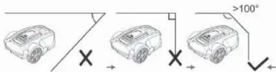
When installing perimeter wire in a corner of the lawn, the corner angle must be greater than 100 degrees, preferably 135 degrees. Corner angles of less than 100 degrees are not suitable for the free movement and mowing of the robotic lawn mower.
The width between the 2 lines of the perimeter wire in the passages should be greater than 50 cm. If the lawn mower has to pass through a passage of less than 50 cm, the working zone should be separated. See "Lawn Type with Main Zone and Subzones" on page 11.
Extending the Perimeter Wire
The perimeter wire can be extended simply by twisting the two wire ends together. To secure the joined wire sections, you can use insulating tape.
The total length of the perimeter wire shall not exceed 300 metres.


IMPORTANT INFORMATION
Remember to use insulating tape to protect the connected wire sections; otherwise, moisture in the soil could cause oxidation of unprotected wires, eventually interrupting the circuit.


CONNECTING THE PERIMETER WIRE
Once you have fi nished laying the perimeter wire and guiding it back to the charging base, you can use the combination pliers to cut the remaining wire and connect the end to the left connector, which is marked with a "B".
The frequency of the perimeter wire is 0–148.5 kHz.

CHECKING PERIMETER WIRE
Check the perimeter wire signal by the colour of the two-colour LED indicator on the charging base.
If this LED indicator continuously shines green, the perimeter wire and power adapter are properly connected.
If the lawn mower is still charging, the LED indicator shines red.
If it blinks green, it means that the perimeter wire is not connected or is broken. Check that the 2 connectors are well connected to the ends of the perimeter wire.
| Two-colour LED indicator status Green Red | ||
| The power adapter and perimeter wire are properly connected to the power source Lit Not lit | ||
| The lawn mower is charging in the charging base Not lit Lit | ||
| Perimeter wire is broken or not connected to the charging base Blinks Not lit | ||
| Power adapter failure or power failure Not lit Not lit |
FIRST START
Before you can use the robotic lawn mower, you must set the date and time.
- Place the robotic lawn mower within its working area.
- Open the control panel cover, then press the switch ⏻.
- Confirm the password (see instructions in the section "Security" on page 22). After opening the control panel cover, you must confirm the password.
- Set the local date and time. Details on how to do this can be found in the section "Settings" on page 22.
- Press the START button() and close the cover, the mower will beep for 2 seconds and then start moving.
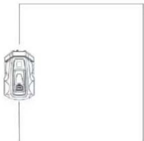
TEST PARKING IN THE CHARGING BASE
Before using the robotic lawn mower, make sure that it can follow the perimeter wire to the charging base and that it parks easily in the charging base.
Perform the following test:
Use the steps in the section "First Start" on page 18.
- While the robotic mower is moving within the working area, press the STOP.
- Open the control panel cover, confirm the password, press the HOME button ( ) and then close the cover.
- The robotic lawn mower will follow the perimeter wire clockwise to the charging base and then park into it. The test is only considered successful if the robotic lawn mower correctly follows the perimeter wire to the charging base and parks in it on the first attempt. If the robotic lawn mower fails on the first attempt, it will automatically try again. Installation is not correct if the robotic lawn mower needs two or more attempts to park in the charging base. If this is the case, check that the charging base and the perimeter wire are installed in accordance with the instructions in sections "Installing and Connecting the Charging Base" on page 13, "Installation of the Perimeter Wire" on page 14 and "Checking Perimeter Wire" on page 17.
IMPORTANT INFORMATION
The HOME function can only be used when the robotic lawn mower is inside the working area.
natural_image
Simple line drawing of a car with a handle and two wheels, connected by a curved arrow (no text or symbols)5. CONTROL PANEL
The control panel cover protects the display from prolonged exposure to sunlight. Without this protection, the display could easily be damaged by prolonged strong sunlight, shortening its lifespan.
Open the cover to access the control panel.
All commands for the robotic lawn mower are entered and settings are made through this control panel.
All functions are accessible through several menus.
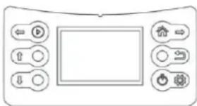
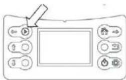
The control panel consists of a display and six buttons.
All information is displayed on the screen and all input is done using the buttons.
IMPORTANT INFORMATION
After completing operations on the control panel, always close the control panel cover to allow the robotic lawn mower to start. If the cover is not closed, the message "Close Cover" will appear on the display and the robotic lawn mower will not start.

When you press the STOP button and open the cover, the home screen appears, showing the date, time, selected working zone, rain sensor status and battery status.
- If the timer is not set for any scheduled daily work, "Standby" is displayed at the top of the screen.
- If the timer is set to daily work, the selected working zone is displayed at the top of the screen.
- The rain symbol ( ) indicates that the rain sensor is activated (on). If the rain sensor is not activated (off), this symbol is not displayed.
- The battery status symbol ( [☐]) shows the remaining charge level. The six buttons are divided into two groups: operation selection buttons and multi-function buttons.

OPERATION SELECTION
Buttons for selecting an operation include:
| Symbol Button Name | Function | |
| ↑ | UP Move the cursor up or increase numerical value | |
| ↓ | DOWN Move the cursor down or decrease numerical value | |
| → | BACK Exit the current interface, return to a higher-level menu | |
BUTTONS WITH MULTIPLE FUNCTIONS
| Symbol Button Name | Function | |
| START | Main function: manually start the robotic lawn mower | |
| Secondary function: move cursor to the left | ||
| HOME | 1. Send the robot back to the charging base and end the current work (if the robot has not completed the planned time after a full charge, it will resume work) | |
| 2. Move the cursor to the right | ||
| 3. Activate cutting on the perimeter wire: move the mower out of the charging base after pressing the "HOME" button | ||
| POWER SWITCH | Single press: Switch on the robot3 seconds long press: Switch off the robot | |
| Selection enters a sub-menu or confi rms individual settings |
Usually the main functions of these two buttons are applied.
Only during the setup process, after pressing the SET button (☐), will the secondary function of these two buttons be applied.
Once the setup is complete, the secondary function of these buttons will be disabled and the main function will be applied.
The two multi-function buttons offer different functions, depending on where you are in the menu structure.
6. MENU FUNCTIONS AND HOW TO SET THEM UP
MAIN MENU
When you press the STOP button and open the cover, press the SET button on the control panel and the main menu will appear on the screen.

flowchart
graph TD
    A["←"] --> B["Play"]
    C["↑"] --> D["Circle"]
    E["↓"] --> F["Circle"]
    G["→"] --> H["House"]
    I["→"] --> J["Switch"]
    K["→"] --> L["Security"]
    M["→"] --> N["Lock"]
    O["→"] --> P["Security"]
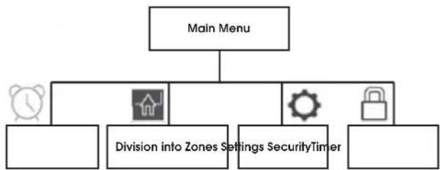
The main menu offers four options:
- Timer
- Division into zones
- Settings
- Security
Each of the menus contains a range of sub-menus.
Through them, you have access to all functions for setting up the robotic mower.
Navigating between Menus
To navigate the main menu and sub-menus, you can use the operation selection buttons and multi-function buttons.
By pressing the SET button (☐), you enter the main menu, then use the right button (A→) to move the cursor and select a sub-menu; pressing the SET button again confirms your choice and enters the sub-menu. After completing the settings in the sub-menus, you can press the BACK button (☐) to go back to a higher level, or you can close the cover to return directly to the home page.
Sub-Menus
Some sub-menus contain pre-selected options. This means that these options are chosen. By pressing the DOWN button (↓), you can toggle between "On" and "Off" to activate or deactivate a specific function.
In some sub-menus, you need to enter information (date, time, etc.) using the control panel.
STRUCTURE OF MENUS
Main menu:
flowchart
graph TD
    A["Main Menu"] --> B["Division into Zones Settings"]
    A --> C["Security Timer"]
    A --> D["Lock Icon"]
    B --> E["Alarm Icon"]
    C --> F["Button Icon"]
    D --> G["Monitor Icon"]
Sub-menu:

flowchart
graph TD
    A["Time"] --> B["Which day"]
    A --> C["Which zone"]
    A --> D["Which time"]
    B --> E["Sun"]
    B --> F["Mon"]
    B --> G["Tue"]
    B --> H["Wed"]
    B --> I["Thu"]
    B --> J["Fri"]
    B --> K["Sat"]
    B --> L["Whole week"]
    C --> M["ON/OFF Zone 1"]
    C --> N["Zone 2"]
    C --> O["Zone 3"]
    C --> P["Zone 4"]
    D --> Q["00:00-00:00"]
    R["Division into Zones"]

flowchart
graph TD
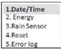
A["Settings"] --> B["Date/Time Energy"]
A --> C["Rain Sensor Reset Error Log"]
A --> D["On"]
A --> E["Off"]
A --> F["Delete all subzones"]
A --> G["Delete all time work"]
H["Security"] --> I["Change password"]
H --> J["ON/OFF screen lock"]
B --> K["Yyyy-mm-dd XXXX"]
B --> L["00:00"]
C --> M["Normal"]
C --> N["ECO"]
D --> O["On"]
E --> P["Off"]
F --> Q["Delete all subzones"]
F --> R["Delete all time work"]
TIMER
The lawn should not be mown too frequently to achieve the best results. If the robotic lawn mower mows too often, the lawn may appear overly flattened. In addition, the robotic lawn mower is subject to unnecessary wear and tear.
The timer function is an ideal means to set the time during which the robotic lawn mower should not mow, for example, when children are playing in the garden. Use the timer function (see "Timer Start") to ensure that your lawn is not trampled.
Before use, calculate how long the robotic lawn mower needs to work based on the working capacity specified in the table below.
| Tabular working capacity | |
| Model Working capacity | |
| FZRR 5650-A About 15 m | ^2 per hour |
| FZRR 5950-A About 15 m | ^2 per hour |
Example
If the working area is 300m^2 , the FZRR 5950-A mower can work for 20 hours a day. This time includes both the mowing time and the charging time. These times are approximate and depend, for example, on the quality of the grass, the sharpness of the blade and the age of the battery.
IMPORTANT INFORMATION
Use the timer to avoid mowing when children or pets are on the lawn.
If the size of the lawn allows it, the quality of the grass can be further improved if it is mowed every other day instead of several hours a day. The grass also benefits from complete rest for at least three days once a month.
DIVISION INTO ZONES
In this section, you will primarily learn how to create subzones for the robotic lawn mower. For information on dividing the lawn into zone, see sections "Types of Lawns" on page 11 and "Installation of the Perimeter Wire" on page 14.
Note:
When dividing into zones, the robotic lawn mower must leave the charging base. Dividing into zones is achieved by setting different memory points for different working zones.
The memory point is a specific point on the perimeter wire and the initial position of the mower in each working zone.
In the main zone, the predefined memory point is the location of the charging base.
IMPORTANT INFORMATION
A memory point cannot be set at a corner or narrow passage.
Set additional memory points as follows:
- Ensure that the robotic lawn mower is correctly parked in the charging base.
- Open the control panel cover and press the SET button to enter the main menu.
- Press the right button ( ) to move the cursor to the zone division symbol.

Add Zone-2
- Press the SET button to confirm the selection of zone settings, the screen will display "Add Zone-2".
- Press the SET button to start the setup. The robotic lawn mower backs out of the charging base, turns 180 degrees and starts moving counterclockwise along the perimeter wire. The screen will display "GO".
- When the mower reaches a position suitable for setting memory point 2 (see examples in the figure above), press the STOP button on the mower. The mower stops at this point and saves it as memory point 2. The display will show "Zone-2 Finished, Next Zone, etc.".
- Press the SET button to continue setting additional memory points following the procedure specified above.
Zone-2 Finished
Next Zone...
The exact starting position in each subzone will deviate slightly from the memory point.
If you want to change or modify the zones, you can directly set it again following the steps above; the old setting will be replaced with the new one.
When setting the division of zones, the mower does not mow.
SETTINGS
Date/Time
The default date format is year/month/date and the time is a 24-hour format.
-
Open the control panel cover and press the SET button to enter the main menu.
-
Press the right button ( ⇧) to move the cursor to the Settings symbol ()
-
Press the SET button to enter the Settingssub-menu.
-
Press the SET button to enter the Date/Time setting interface.
-
Press the DOWN ☐ or UP (↑) button to change the numbers corresponding to the YEAR.
-
Press the right button (→) to move the cursor to the numbers representing the MONTH or DATE.
-
Press the DOWN(or UP (↑)) button to change the numbers corresponding to the MONTH or DATE.
Use a similar procedure on the control panel as described above to set the TIME.
- Press the SET button to confirm the Date/Time setting.
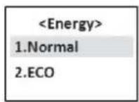
Energy
There are two energy consumption modes to choose from:
Normal – the mower's movement speed and cutting speed are as indicated in the technical information (see Chapter 10).
It is used for normal grass cutting or grass higher than 8 cm. The robotic lawn mower is preset in this mode.
ECO – the mower's movement speed and cutting speed are reduced by 10–30% compared to normal mode.
This mode is recommended for mowing lower grass, daytime lawn maintenance or night-time operation.
Use a similar procedure on the control panel as described above to set the energy consumption mode.
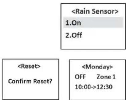
Rain Sensor
The robotic lawn mower can also cut in the rain or in high humidity conditions; however, wet grass easily sticks to the robotic lawn mower, and there is a higher risk of slipping on steeper slopes.
The rain sensor is enabled by default.
Use a similar procedure on the control panel as described above to activate or deactivate the rain sensor.
Reset
During a reset, the zone division settings and timer settings will be erased, so think carefully before using this function.
SECURITY
Setting a four-digit password to lock the screen display can help prevent children or other persons who are not familiar with the safe operation of the mower from using it without supervision.
It also functions as an anti-theft feature, preventing unauthorised persons from operating the mower.
The default password is: 0000
If needed, you can change it and choose a new password.
Use a similar procedure on the control panel as described above to change the password.
You can also turn the screen lock on or off.
If you enable the screen lock, the robotic lawn mower will request a password every time you open the cover. The screen lock is preset to the "OFF" state.
Use a similar procedure on the control panel as described above to activate or deactivate the screen lock.


7. USAGE
CHARGING A DISCHARGED BATTERY (SEE THE "BATTERY CHARGING" SECTION)

WARNING
Before starting the robotic lawn mower, carefully read the safety instructions.

WARNING
Keep your hands and feet well away from the rotating blades. Never place hands or feet near the mower body when the motor is running.


WARNING
Never use the robotic lawn mower when people, especially children, or pets are present in the mowing area.
STARTING
The robotic lawn mower can be started in two ways:
Quick start by manually pressing the START button ( ▶ ) and automatic start based on timer settings.
Quick Start
When the robotic lawn mower is in its working area, you can perform the quick start by pressing the START button.
- Move the robotic lawn mower to the working zone you want to mow.
- Open the control panel cover and switch on the mower by pressing the switch button.
- Press the START button ( ▶ ) and then close the cover.
The robotic lawn mower will start working until the battery voltage drops, then it will automatically return to the charging station. You can also press the STOP button to stop the robotic lawnmower manually.
Cutting on the Perimeter Wire
The robotic lawn mower can also cut grass on the perimeter wire, which is skipped when mowing in the working area.
Grass cutting on the perimeter wire can only be controlled manually.
Perform the operation in the following steps:
- Ensure that the robotic lawn mower is correctly parked in the charging base.
- Open the control panel cover.
- Enter the password if screen lock is activated (turned on).
- Press the HOME button).
- Close the cover.
natural_image
Simple line drawing of a car with no text, numbers, or symbolsThe robotic lawn mower will leave the charging base, turn 180 degrees, and start cutting the grass above the wire.
Before the blade disc starts running, there will be 5 beeps for 2 seconds.
After the mower completes one circuit around the perimeter wire, it touches the charging base and rotates 180 degrees. It then returns along the perimeter wire back to the charging base, but this time without cutting. Then it stops working and parks in the charging base.
IMPORTANT INFORMATION
To achieve the best cutting of grass along the perimeter wire, be sure to remove all obstacles near the perimeter wire that could activate the collision sensor, such as branches, stones, toys, fruits, etc.
Timer Start
When setting the timer, use the following sequence:
Which day-> Which zone-> Which time
- Open the control panel cover and press the SET button to enter the main menu.
- The cursor is on the TIMER symbol; press the SET button to enter the sub-menu.


flowchart
graph LR
    A["1.Monday\n2.Tuesday\n3.Wednesday\n4.Thursday"] --> B["<Monday>\nON Zone 1\n10:00->12:30"]
    B --> C["<Monday>\nON Zone 1\n10 :00->12:30"]
- Use a similar procedure on the control panel as described in the section "Date/Time" on page 22 to set the timer for grass cutting on different days and in different zones.
After completing the settings, make sure that the robotic lawn mower correctly parks in the charging station so that it can automatically start when the time comes.
Note:
- For each day, you can only select one working zone.
(For a specific day, you can select any of the defined zones. If you do not divide the area into zones, the main zone is preset as Zone 1);
if you do not want to cut the grass on a certain day, select "OFF" for the Zone selection. - For each day, you can set only one working time.
If, after the first use of the timer function, you find that the grass in a particular zone is not well cut, you can adjust the timer in two ways:
- Choose another day when work will be done in that zone again.
- Extend the working time in that zone so that the mower will cut longer in that area next time.
For more information on the relationship between the length of the working time and the lawn area, see the section "Timer" on page 21.
STOPPING
Pressing the STOP button; the robotic lawn mower will stop, and the blade disc motor will also stop.
If the mower was started using the quick start: When, after pressing the STOP button, you want to start the mower again for daily work, follow the steps in the section "Quick Start" on page 23.
If the mower was started using the timer: After pressing the STOP button, it will not continue with the remaining daily work plan, it will stay in the charging base until you delete the daily work plan and start it manually using quick start or automatically deactivate the timer set for the next day.
natural_image
Line drawing of a robotic car with a handle and sensor array (no text or symbols)SWITCHING OFF
- Press the STOP button.
- Hold down the power switch ⏻ for 3 seconds to switch off the power.
Always switch off the robotic lawn mower if it needs maintenance or if it needs to be moved out of the working area.

CUTTING HEIGHT ADJUSTMENT
The cutting height can be set from 3 to 5 cm.
How to adjust the cutting height:
- Press the STOP button to stop the robotic lawn mower and open the cover.
- Turn the height adjustment knob to the desired position.
- Turn clockwise to increase the cutting height.
- Turn counterclockwise to reduce the cutting height.

IMPORTANT INFORMATION
During the first week after a new installation, the cutting height must be set to MAX (5 cm) to avoid damage to the perimeter wire. After that, the cutting height can be gradually reduced every other week until the desired height is reached.
8. MAINTENANCE
Regularly inspect and clean the robotic lawn mower, and replace worn parts as needed to improve its operational reliability and ensure a longer lifespan. For more information on cleaning, see the section "Cleaning" on page 25.
At the beginning of using the robotic lawn mower, it is necessary to check the blade disc and blades once a week. If wear during this time is low, the inspection interval can be extended.
It is crucial for the blade disc to rotate smoothly. The edges of the blades should not be damaged. The lifespan of the blades varies considerably and depends, for example, on the following factors:
- Operating time and size of the working area
- Type of grass
- Type of soil
• Presence of objects such as pine cones, fallen fruit, toys, tools, rocks, roots, etc.
The typical lifespan is 2–4 months when used on areas larger than 300 m ^2 and longer for smaller areas.
The procedure for changing the blades can be found in the section "Blade Replacement" on page 26.
IMPORTANT INFORMATION
Working with dull blades results in poorer mowing results. Grass edges are not cleanly cut, requiring more energy, causing the robotic lawn mower to cover a smaller area.
WINTER STORAGE
Robotic Lawn Mower
Before storing the robotic lawn mower for winter, thoroughly clean the mower. See "Cleaning" on page 25.
To ensure battery functionality and lifespan, it is crucial to fully charge the robotic lawn mower before winter storage. See “Battery Charging” on page 14.
Check the condition of easily wearable parts, such as blades and wheels. If necessary, replace them to ensure the robotic lawn mower is in good condition before the next season.
Apply a bit of anti-corrosion oil to the blades and screws securing the blades to prevent corrosion.
The recommended ambient temperature range for operating the robotic lawn mower is 5–45 °C. In winter, once the temperature in the garden remains consistently below 5 °C, store the mower in a dry place where it will not freeze, preferably in its original packaging.
IMPORTANT INFORMATION
Before winter storage, the battery must be fully charged. If the battery is not fully charged, it may be damaged and, in some cases, rendered unusable.
Charging Base
Store the charging base and power adapter indoors. You can leave the perimeter wire in the ground. The ends of the wire should be protected from moisture by placing them, for example, in a container with grease.
If the charging base cannot be stored indoors, disconnect it from the power supply throughout the winter.
AFTER WINTER STORAGE
Before the first use, check if cleaning is needed, especially the charging stakes on the charging base and the charging strips in the robotic lawn mower. If the charging stakes or charging strips appear burnt or coated, clean them with fine sandpaper. Also, verify that the date and time on the robotic lawn mower are correctly set.
CLEANING
It is essential to keep the robotic lawn mower clean. A mower with a large amount of stuck grass will struggle on slopes. It is recommended to use a brush for cleaning.
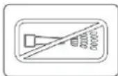
IMPORTANT INFORMATION
Never use a pressure washer or running water to clean the robotic lawn mower. Never use solvents for cleaning.
Chassis and Blade Disc
- Hold down the power switch for 3 seconds to switch off the power.
- Wear protective gloves.
- Turn the robotic lawn mower upside down.
- Clean the blade disc and chassis using a dish brush.
Simultaneously, check if the blade disc rotates freely and does not rub against the blade disc guard.
If long grass stems or other objects get inside, they may impede the blade disc.
Even a slight braking effect can lead to increased consumption and longer mowing time, and in the worst case, prevent the robotic lawn mower from cutting a large lawn.
Chassis
Clean the underside of the chassis. Use a brush or damp cloth.
Wheels
Clean the area around the front and rear wheels, as well as the wheel holder or shaft.
Body
Use a damp, soft sponge or cloth to clean the body. If the body is heavily soiled, a soap solution or dishwashing detergent may be necessary.
Charging Base
Regularly clean the charging base from grass, leaves, twigs, and other objects that may hinder parking.
TRANSPORTATION AND DISPOSAL
Secure the machine during transportation. It is important that the robotic lawn mower remains stationary, e.g. when transported between lawns.
The lithium-ion batteries contained are subject to the requirements of dangerous goods legislation.
During commercial transport, e.g. by third parties or forwarders, special requirements for packaging and labelling must be observed.
When preparing the item for transport, consult with a hazardous materials expert. Also, comply with all applicable national regulations.
DURING STORMS
To reduce the risk of damage to electrical components in the robotic lawn mower and its charging base, it is recommended to disconnect all connections to the charging base (power and perimeter wire) in the event of a storm.
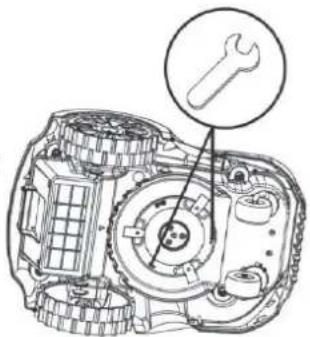
BLADE REPLACEMENT

WARNING
When replacing, always use original blades.
There are three blades screwed onto the blade disc of the robotic lawn mower. All three blades must be replaced simultaneously to maintain balance in the cutting system.
How to replace the blades:
- Hold down the power switch ⏻ for 3 seconds to switch off the power.
- Wear protective gloves.
- Turn the robotic lawn mower upside down.
- Insert the spanner into one of the two holes in the disc and secure its end in the groove of the blade disc guard to prevent the disc from rotating.
- Unscrew the centre screw on the blade disc, and then unscrew the securing screws of the blades using a flat or cross-point screwdriver.
- Screw in the new blades and mount the blade disc.
BATTERY REPLACEMENT
The battery is maintenance-free, but its lifespan is limited to 2 to 4 years.
The battery lifespan depends on the length of the season and the number of hours per day the robotic lawn mower operates. A long season or many hours of daily use means the battery needs replacing more frequently.
natural_image
Technical line drawing of a mechanical assembly with a wrench icon (no text or labels)IMPORTANT INFORMATION
At the end of the season, before winter storage, fully charge the battery.
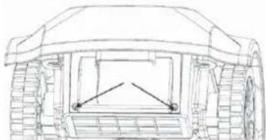
Battery Replacement
If the working time of the robotic lawn mower between individual charges is shorter than usual, it indicates that the battery is aging and needs replacement. The battery is fine as long as the robotic lawn mower can maintain a well-cut lawn.
IMPORTANT INFORMATION
Always use only original batteries. Compatibility with other batteries cannot be guaranteed.
- Hold down the power switch for 3 seconds to switch off the power.
- Turn the robotic lawn mower upside down. Place the robotic lawn mower on a soft, clean surface to avoid scratching its body and display cover.
- Clean the area around the battery cover.
- Unscrew the two screws on the battery cover and remove the cover.
- Pull out the old battery and disconnect the connectors between the battery and the main board.
- Insert the new original battery and reconnect the connectors.
- Remount the battery cover. If the seal on the battery cover is visibly damaged, the battery cover must be replaced.
- Screw back the two screws holding the battery cover.
natural_image
Technical line drawing of a mechanical vehicle showing front, side, and top views (no text or symbols)9. TROUBLESHOOTING
This chapter lists a number of error codes and audible signals with different time intervals that can occur in the event of a malfunction. For each error code, the potential cause and steps to be taken are outlined.
This chapter also includes symptoms that may help if the robotic lawn mower is not operating as expected.
ERROR CODES
Below are error codes that may appear on the display of the robotic lawn mower, along with brief descriptions of the associated problems. When any of these error codes are displayed, the mower will beep five times at one-second intervals
to draw attention. Press the BACK button (←) to exit the interface displaying the current error code.
If the same error code appears frequently, contact an authorised dealer or service.
| Error Code Problem Cause Steps | |||
| Error 1 No boundaries No connection between the perimeter | wire and the charging base | Restore the connection between the perimeter wire and the charging base. | |
| Power adapter plug is loose or pulled out of the socket. | Reinsert the plug back into the socket. | ||
| Perimeter wire is broken Connect the broken wire. | |||
| Switching off Park the mower correctly in the charging base to prepare it for the next start. | |||
| Failed to return to the working area Check the angle of the boundary line and the lawn area. | |||
| Error 2 Obstacle detection error Fault in the PCBA of the obstacle sensor Replace the faulty PCBA. | |||
| Error 3 Collision detection error Fault in the PCBA of the obstacle sensor Replace the faulty PCBA. | |||
| Cable connecting the PCBA of the collision sensor and the main board is broken | Replace the old cable. | ||
| Error 4 | Mower lifted | Mower was lifted | Place the lawn mower on the ground and restart it. |
| Front wheel shaft is stuck (cannot move smoothly) | Remove any mud or grass from the shaft and apply a little lubricant. | ||
| Both front wheels fell into a hole or trench | Fill the hole or trench with soil. | ||
| Error 5 Excessive slope Slope of the incline is greater than 25°; someone lifted the mower | Refer to sections "Slopes" on page 10 and "Laying the Perimeter Wire" on page 16 for information on how to avoid slopes. Place the lawn mower on the ground and restart it. | ||
| Error 6 | Overturned | The slope of the incline is greater than 25° | Refer to sections "Slopes" on page 10 and "Laying the Perimeter Wire" on page 16 for information on how to avoid slopes. |
| Someone overturned the mower | Turn the mower over and start it again. | ||
| Error 7 | Battery error | Battery self-check detected an error | Replace the old battery. |
| Error 8 | Boundary error | Outside the working area | Switch on the machine in the working area. |
| Error 9 | Board error | Main board self-check detected an error | Replace the faulty PCBA. |
| Error 10 | Motor malfunction | Fault in the PCBA of the motor controller | Replace the faulty PCBA. |
| Error 11 | Motor error | Fault in the PCBA of the motor controller or in the motor | Replace the old PCBA or motor. |
| Error 12 | Charging error | Battery charging is blocked because the temperature is too high or too low | Leave the mower in the shade and try again when the ambient temperature is suitable. |
| Error 13 | System error | Software self-check detected an error on the main board | Replace the faulty PCBA. |
SYMPTOMS
If the robotic lawn mower is not working as expected, follow the troubleshooting guide below.
| Symptom Cause Steps | ||
| Nothing is displayed on the screen Power switch is off | Turn on the power switch. | |
| Battery is too low Park the robotic lawn mower in the charging base to recharge. | ||
| Fault in the PCBA board with display Replace the faulty PCBA. | ||
| The robotic mower does not start after pressing the START button | Charging contacts are not plugged into the charging inputs (the lightning symbol does not appear next to the battery symbol) | Move the lawnmower closer to the charging base. |
| Daily work timer is set Change the timer settings by cancelling the daily work. | ||
| The robotic lawn mower crosses over the perimeter wire | Perimeter wire is intersected Properly lay the perimeter wire. | |
| Fault in the PCBA board in the charging base Replace the old PCBA or charging base. | ||
| Calendar reverted to factory settings Button cell on the main board is discharged Replace the old button cell. | ||
| Faulty collision sensor | Spring in the collision sensor is not functioning | Replace the old spring in the collision sensor. |
| Magnet from the collision sensor fell out | Install a new magnet. | |
| Charging problems | Battery is old and worn out | Replace the old battery. |
| The robotic lawn mower cannot connect correctly using the charging contacts (the lightning bolt symbol is not displayed next to the battery symbol) | Park the robotic lawn mower further into the charging base; or reinstall the charging base. | |
| Charging contacts disconnected from the internal PCBA board. | Restore the connection or install a new PCBA. | |
| Loud noise | Blade is damaged | Replace the old blade. |
| Blade disc is damaged | Replace the old blade disc. | |
| Height adjustment knob is worn out | Replace the old knob. | |
- TECHNICAL SPECIFICATIONS
| Model Number FZRR 5650-A FZRR 5950-A | ||
| Ideal lawn area (m2) 600 900 | ||
| Maximum lawn area (m2) 900 1,200 | ||
| Rated power (W) 84 84 | ||
| Type of battery Li-Ion Li-Ion | ||
| Rated voltage (V) 20 20 | ||
| Battery capacity (Ah) 2.0 4.0 | ||
| Power adapter parameters | Input: 100-240 V~50/60 Hz, Output: 21 V DC | Input: 100-240 V~50/60 Hz, Output: 21 V DC |
| Charging current (A) | 2.0 | 2.0 |
| Electrical safety class | III | III |
| Charging time (min) | 60 120 | |
| Typical mowing time per charge (min) | 90 150 | |
| Mowed area per charge (m2) | 22.5 | 37.5 |
| Mowing speed (m2/h) | 15 | 15 |
| Idling speed (rpm) 4,000 4,000 | ||
| Mowing width (cm) | 17 | 17 |
| Mowing height (cm) | 3-4-5 3-4-5 | |
| Number of blades | 3 | 3 |
| Minimum passage width (cm) | 50 50 | |
| Mower cover | IPX4 | IPX4 |
| Charging Base | IPX4 | IPX4 |
| Charger | IP67 | IP67 |
| Measured acoustic pressure level (dB(A)) | 54.4 | 54.4 |
| Guaranteed acoustic pressure level (dB(A)) | 57 | 57 |
| Slope | 25° | 25° |
| Length of boundary wire (m) | 150 | 200 |
| Stakes (number) | 150 | 200 |
| Max. permissible length of perimeter wire | 300 300 | |
| Mower size (cm, L x W x H) | 49 x 34 x 22 | 49 x 34 x 22 |
| Mower weight (kg) | 6.8 | 7.2 |
| Charging base weight (kg) | 0.85 | 0.85 |
| Packaging size (cm, L x W x H) | 60 x 41 x 32.5 60 x 41 x 32.5 | |
| Total weight (kg) | 6.8 | 7.2 |
11. DISPOSAL
INSTRUCTIONS AND INFORMATION REGARDING THE DISPOSAL OF USED PACKAGING MATERIALS
Dispose of packaging material at a public waste disposal site.
DISPOSAL OF USED ELECTRICAL AND ELECTRONIC APPLIANCES
The meaning of the symbol on the product, its accessory or packaging indicates that this product shall not be treated as household waste. Please, dispose of this product at your applicable collection point for the recycling of electrical & electronic equipment waste. Alternatively in some states of the European Union or other European states you may return your products to your local retailer when buying an equivalent new product. The correct disposal of this product will help save valuable natural resources and help in preventing the potential negative impact on the environment and human health, which could be caused as a result of improper liquidation of waste. Please ask your local authorities or the nearest waste collection centre for further details. The improper disposal of this type of waste may fall subject to national regulations for fines.
For business entities in the European Union
If you wish to dispose of an electrical or electronic device, request the necessary information from your seller or supplier.
Disposal in other countries outside the European Union
If you wish to dispose of this product, request the necessary information about the correct disposal method from local government departments or from your seller.

This product meets all the basic EU regulation requirements that relate to it.
Changes to the text, design and technical specifications may occur without prior notice and we reserve the right to make these changes.
User manual in the original language.

natural_image
Front view of a computer control panel with buttons and display (no text or symbols)DŮLEŽITÉ INFORMACE
natural_image
Line drawing of a robotic device with a handle and gear (no text or symbols)Vzorec pohybu
natural_image
Line drawing of a car on an inclined plane with a 0-20° angle标注 (no text or symbols beyond the angle marker)
TYPY TRÁVNÍKŮ
natural_image
Line drawings of three different tools: a hammer, a pliers, and a spool (no text or symbols)INSTALACE A ZAPOJENÍ NABÍJECÍ ZÁKLADNY

natural_image
Technical line drawing of a mechanical component with no visible text or symbols
natural_image
Technical line drawing of a mechanical housing or enclosure with internal components and mounting holes (no text or symbols)
natural_image
Line drawing of a robotic car with visible wheels and structural components (no text or symbols)KONTROLA OBVODOVÉHO DRÁTU
natural_image
Simple line drawing of a car with a handle and two wheels, connected by a curved arrow (no text or symbols)5. OVLÁDACÍ PANEL
DŮLEŽITÉ INFORMACE
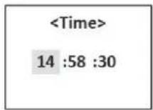


7. POUŽITÍ
NABITÍ VYBITÉHO AKUMULÁTORU (VIZ „NABÍJENÍ AKUMULÁTORU“)

VAROVÁNÍ
natural_image
Line drawing of a control panel with buttons and a screen (no text or symbols)natural_image
Simple line drawing of a car viewed from above, no text or symbols presentnatural_image
Line drawing of a robotic car with a handle and sensor array (no text or symbols)VYPNUTÍ
NASTAVENÍ VÝŠKY SEČENÍ
DŮLEŽITÉ INFORMACE
natural_image
Technical line drawing of a vehicle chassis with front wheel and rear wheels (no text or symbols)9. ŘEŠENÍ PROBLÉMŮ
DÔLEŽITÉ INFORMÁCIE
natural_image
Line drawing of a robotic car with a handle and gear (no text or symbols)Vzorec pohybu
natural_image
Technical line drawing of a car with a 0-20° angle marked on the side (no text or symbols beyond the angle label)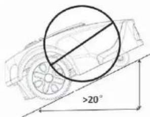
TYPY TRÁVNIKOV
natural_image
Simple line drawings of three tools: a hammer, a pliers, and a shovel (no text or symbols)INŠTALÁCIA A ZAPOJENIE NABÍJACEJ ZÁKLADNE
natural_image
Technical line drawing of two mechanical components with mounting holes and a diagonal line (no text or symbols)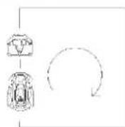
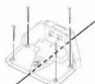
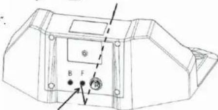
natural_image
Technical line drawing of a mechanical component with no visible text or symbols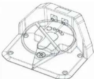
natural_image
Technical line drawing of a mechanical housing or enclosure with internal components and mounting holes (no text or symbols)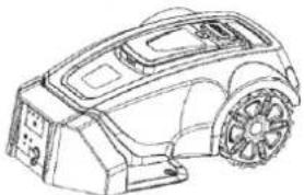
natural_image
Line drawing of a robotic car with visible frame and wheels (no text or symbols)2. Zakopte drôt.
KONTROLA OBVODOVÉHO DRÔTU
natural_image
Simple line drawing of a vehicle with a sensor and two wheels, connected by a circular arrow (no text or symbols)5. OVLÁDACÍ PANEL
DÔLEŽITÉ INFORMÁCIE
Zone-2 Finished Next Zone...
NASTAVENIE
Dátum/čas
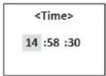


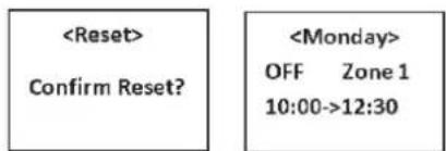


7. POUŽITIE
NABITIE VYBITÉHO AKUMULÁTORA (POZRITE „NABÍJANIE AKUMULÁTORA“)

VAROVANIE
natural_image
Line drawing of a digital device control panel with buttons and a screen (no text or symbols)natural_image
Top-down line drawing of a car silhouette (no text or symbols)natural_image
Line drawing of a robotic car with a handle and sensor array (no text or symbols)VYPNUTIE
NASTAVENIE VÝŠKY KOSENIA
DÔLEŽITÉ INFORMÁCIE
natural_image
Technical line drawing of a mechanical assembly with a wrench icon pointing to a component (no text or labels present)VÝMENA AKUMULÁTORA
natural_image
Technical line drawing of a vehicle rear view showing engine, dashboard, and wheel components (no text or labels)9. RIEŠENIE PROBLÉMOV


FONTOS INFORMÁCIÓK
natural_image
Line drawing of a robotic device with no visible text or symbolsMozgásminta
natural_image
Technical line drawing of a car on an inclined plane with a 0-20° angle标注 (no text or symbols beyond the angle marker)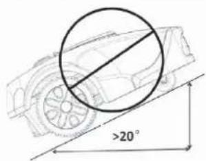
natural_image
Technical line drawings of mechanical components and a circular motion diagram (no text or symbols)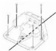
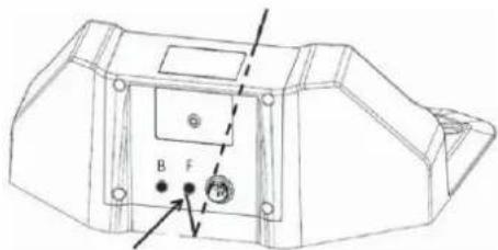
natural_image
Technical line drawing of a mechanical component with labeled parts (no readable text or symbols)
natural_image
Technical line drawing of a mechanical housing or enclosure with internal components and mounting holes (no text or symbols)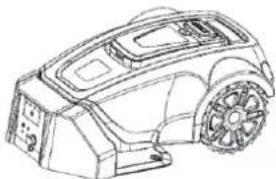
natural_image
Line drawing of a robotic car with visible wheels and dashboard (no text or symbols)HATÁROLÓ VEZETÉKEK ELLENŐRZÉSE
natural_image
Simple line drawing of a vehicle with two components and a curved arrow indicating rotation (no text or symbols)5. MÜKÖDTETÖ PANEL
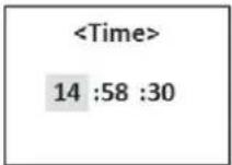

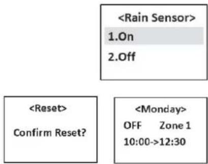


7. HASZNÁLAT
LEMERÜLT AKKUMULÁTOR TÖLTÉSE (LÁSD „AZ AKKUMULÁTOR TÖLTÉSE” FEJEZETET)

FIGYELEM
natural_image
Top-down line drawing of a car silhouette (no text or symbols)FONTOS INFORMÁCIÓK
natural_image
Line drawing of a robotic car with a handle and sensor array (no text or symbols)KIKAPCSOLÁS
8. KARBANTARTÁS
natural_image
Technical line drawing of a mechanical assembly with a wrench icon pointing to a component (no text or labels present)AZ AKKUMULÁTOR CSERÉJE
natural_image
Technical line drawing of a vehicle chassis with no visible text or symbols9. HIBAELHÁRÍTÁS
WAŻNE INFORMACJE
natural_image
Line drawing of a robotic car with a handle and gear (no text or symbols)Wzór ruchu
natural_image
Illustration of a person reading a book with tools and equipment nearby (no text or symbols)natural_image
Line drawings of three different tools: a hammer, a pliers, and a spool (no text or symbols)INSTALACJA I PODŁĄCZENIE STACJI ŁADUJĄCEJ
natural_image
Technical line drawings of mechanical components with no visible text or symbols
natural_image
Technical line drawing of a mechanical component with labeled parts (no readable text or symbols)
natural_image
Technical line drawing of a mechanical housing or enclosure with internal components and mounting holes (no text or symbols)
natural_image
Line drawing of a robotic car with visible wheels and dashboard (no text or symbols)WAŻNE INFORMACJE
natural_image
Line drawing of a car with a circular annotation highlighting a specific area (no text or symbols present)KONTROLA PRZEWODU OGRANICZAJĄCEGO
natural_image
Simple line drawing of a mechanical component with a curved arrow indicating rotation (no text or symbols)5. PANEL STEROWANIA

Energia
natural_image
Line drawing of a digital camera control panel with buttons and a screen (no text or symbols)natural_image
Simple line drawing of a car viewed from the side (no text or symbols)natural_image
Line drawing of a robotic vacuum cleaner with a handle and gear (no text or symbols)WYŁĄCZANIE
USTAWIENIA WYSOKOŚCI KOSZENIA
WAŻNE INFORMACJE
natural_image
Technical diagram of a mechanical assembly with a wrench icon pointing to a component (no text or labels present)WYMIANA AKUMULATORA
natural_image
Technical line drawing of a vehicle chassis with no visible text or symbols9. ROZWIAZYWANIE PROBLEMÓW
natural_image
Line drawing of a robotic car with visible frame and wheel (no text or symbols)
- Robotic Lawn Mower USER MANUAL
- TABLE OF CONTENTS
- IMPORTANT SAFETY INSTRUCTIONS
- WARNING:
- FOR DOMESTIC USE ONLY
- PERSONAL SAFETY
- ELECTRICAL SAFETY
- BATTERY SAFETY
- MAINTENANCE
- TRANSPORT
- IMPORTANT INFORMATION
- INTRODUCTION
- LIST OF PARTS
- PACKAGE CONTENTS
- FUNCTIONS
- Working Area
- Cutting Technique
- Operating Mode
- Movement Pattern
- Search Method
- PLANNING
- PLANNING THE LAYING OF THE PERIMETER WIRE
- Objects within the Lawn
- Slopes
- TYPES OF LAWNS
- What does your lawn look like?
- LAWN TYPE WITH MAIN ZONE ONLY
- LAWN TYPE WITH MAIN ZONE AND SUBZONES
- LAWN TYPE WITH SEPARATE ZONES
- Separate zone that can be mowed at one go
- Separate zone that cannot be mowed at one go
- CHOOSING THE LOCATION FOR THE CHARGING BASE
- INSTALLATION
- PREPARATION
- INSTALLING AND CONNECTING THE CHARGING BASE
- Mounting the Charging Base
- Power Adapter Connection
- Charging Base Connection
- BATTERY CHARGING
- INSTALLATION OF THE PERIMETER WIRE
- Best Position of the Perimeter Wire
- Working Area Boundaries
- Boundaries within the Working Area
- Mowing Passages
- Laying the Perimeter Wire
- Extending the Perimeter Wire
- CONNECTING THE PERIMETER WIRE
- CHECKING PERIMETER WIRE
- FIRST START
- TEST PARKING IN THE CHARGING BASE
- CONTROL PANEL
- OPERATION SELECTION
- MENU FUNCTIONS AND HOW TO SET THEM UP
- MAIN MENU
- Navigating between Menus
- Sub-Menus
- STRUCTURE OF MENUS
- TIMER
- DIVISION INTO ZONES
- Note:
- SETTINGS
- Date/Time
- Energy
- Rain Sensor
- Reset
- SECURITY
- USAGE
- CHARGING A DISCHARGED BATTERY (SEE THE "BATTERY CHARGING" SECTION)
- STARTING
- Quick Start
- Cutting on the Perimeter Wire
- Timer Start
- STOPPING
- SWITCHING OFF
- CUTTING HEIGHT ADJUSTMENT
- MAINTENANCE
- WINTER STORAGE
- Robotic Lawn Mower
- Charging Base
- AFTER WINTER STORAGE
- CLEANING
- Chassis and Blade Disc
- Chassis
- Wheels
- Body
- TRANSPORTATION AND DISPOSAL
- DURING STORMS
- BLADE REPLACEMENT
- WARNING
- BATTERY REPLACEMENT
- TROUBLESHOOTING
- ERROR CODES
- DISPOSAL
- INSTRUCTIONS AND INFORMATION REGARDING THE DISPOSAL OF USED PACKAGING MATERIALS
- DISPOSAL OF USED ELECTRICAL AND ELECTRONIC APPLIANCES
- For business entities in the European Union
- Disposal in other countries outside the European Union
- DŮLEŽITÉ INFORMACE
- Vzorec pohybu
- TYPY TRÁVNÍKŮ
- INSTALACE A ZAPOJENÍ NABÍJECÍ ZÁKLADNY
- KONTROLA OBVODOVÉHO DRÁTU
- OVLÁDACÍ PANEL
- POUŽITÍ
- NABITÍ VYBITÉHO AKUMULÁTORU (VIZ „NABÍJENÍ AKUMULÁTORU“)
- VYPNUTÍ
- NASTAVENÍ VÝŠKY SEČENÍ
- ŘEŠENÍ PROBLÉMŮ
- DÔLEŽITÉ INFORMÁCIE
- TYPY TRÁVNIKOV
- INŠTALÁCIA A ZAPOJENIE NABÍJACEJ ZÁKLADNE
- Zakopte drôt.
- KONTROLA OBVODOVÉHO DRÔTU
- NASTAVENIE
- Dátum/čas
- POUŽITIE
- NABITIE VYBITÉHO AKUMULÁTORA (POZRITE „NABÍJANIE AKUMULÁTORA“)
- VYPNUTIE
- NASTAVENIE VÝŠKY KOSENIA
- VÝMENA AKUMULÁTORA
- RIEŠENIE PROBLÉMOV
- FONTOS INFORMÁCIÓK
- Mozgásminta
- HATÁROLÓ VEZETÉKEK ELLENŐRZÉSE
- MÜKÖDTETÖ PANEL
- HASZNÁLAT
- LEMERÜLT AKKUMULÁTOR TÖLTÉSE (LÁSD „AZ AKKUMULÁTOR TÖLTÉSE” FEJEZETET)
- KIKAPCSOLÁS
- KARBANTARTÁS
- AZ AKKUMULÁTOR CSERÉJE
- HIBAELHÁRÍTÁS
- WAŻNE INFORMACJE
- Wzór ruchu
- INSTALACJA I PODŁĄCZENIE STACJI ŁADUJĄCEJ
- KONTROLA PRZEWODU OGRANICZAJĄCEGO
- PANEL STEROWANIA
- Energia
- WYŁĄCZANIE
- USTAWIENIA WYSOKOŚCI KOSZENIA
- WYMIANA AKUMULATORA
- ROZWIAZYWANIE PROBLEMÓW
Brand : Fieldmann
Model : FZRR 5650-A
Category : Robotic mower