
TC53P4-1832IA - Air conditioner TESLA - Free user manual and instructions
Find the device manual for free TC53P4-1832IA TESLA in PDF.

| Product Type | Split Air Conditioner (Indoor + Outdoor) |
| Model | TC53P4-1832IA |
| Brand | Tesla |
| Refrigerant | R32 (Flammable) |
| Cooling Capacity | Approx. 18000 BTU/h |
| Heating Capacity | Heat pump type, approx. 18000 BTU/h |
| Power Supply | 220-240 V ~ 50 Hz |
| Outdoor Unit Dimensions (WxHxD) | 790 x 520 x 280 mm |
| Indoor Unit Dimensions (approx.) | 900 x 300 x 200 mm |
| Control | Remote controller with LCD display |
| Modes | Auto, Cool, Heat, Dehumidify, Fan Only |
| Special Functions | Turbo, Eco, Sleep, Timer (1-24h), Swing (up/down & left/right) |
| Air Filter | Washable mesh filter (clean every 2 weeks) |
| Defrost Function | Automatic defrost (5-12 minutes) during heating |
| Installation Requirements | Minimum room space >5 m², professional installation required |
| Safety Features | Grounding, leakage protection, emergency operation button |
| Environmental | Fluorinated greenhouse gases; GWP = 675 |
Frequently Asked Questions - TC53P4-1832IA TESLA
User questions about TC53P4-1832IA TESLA
0 question about this device. Answer the ones you know or ask your own.
Ask a new question about this device
Download the instructions for your Air conditioner in PDF format for free! Find your manual TC53P4-1832IA - TESLA and take your electronic device back in hand. On this page are published all the documents necessary for the use of your device. TC53P4-1832IA by TESLA.
USER MANUAL TC53P4-1832IA TESLA
Note: All the pictures in this manual are just schematic diagrams, the actual is the standard. Please read this owner's manual carefully and thoroughly before operating the unit! Take care of this manual for future reference.

UPUTSTVO ZA UPOTREBU
Napomena: Sve slike u ovom priručniku su samo šematski dijagrami, fizički proizvod je standard. Molimo Vas da pažljivo i temeljno pročitate ovo uputstvo za upotrebu prije korišćenja uređaja! Sačuvajte ovo uputstvo za buduću upotrebu.

Notes: Air conditioner with R32 refrigerant, if roughly treated, may cause serious harm to the human body or surrounding things.
- The room space for the installation, use, repair, and storage of this air conditioner should be greater than 5 m'.
• Air conditioner refrigerant can not charge more than 1.7kg. - Do not use any methods to speed up defrost or to clean frosty parts except for particular recommended by manufacturer.
- Not pierce or burn air conditioner, and check the refrigerant pipeline wether be damaged.
- The air conditioner should be stored in a room without lasting fire source, for example, open flame, burning gas appliance, working electric heater and so on.
- Notice that the refrigerant may be tasteless.
- The storage of air conditioner should be able to prevent mechanical damage caused by accident.
- Maintenance or repair of air conditioners using R32 refrigerant must be carried out after security check to minimize risk of incidents.
• Air conditioner must be installed with stop valve cover. - Please read the instruction carefully before installing, using and maintaining.
| Symbol Note | Explanation | |
 | WARNING | This symbol shows that this appliance uses a flammable refrigerant. If the refrigerant is leaked and exposed to an external ignition source, there is a risk of fire. |
 | CAUTION | This symbol shows that the operation manual should be read carefully. |
 | CAUTION | This symbol shows that a service personnel should be handling this equipment with reference to the installation manual. |
 | CAUTION | This symbol shows that information is available such as the operating manual or installation manual. |
SAFETY PRECAUTIONS
Incorrect installation or operation by not following these instructions may cause harm or damage to people, properties, etc. The seriousness is classified by the following indications:

WARNING!
This symbol indicates the possibility of death or serious injury.

CAUTION!
This symbol indicates the possibility of injury or damage to properties.
- This appliance can be used by children aged from 8 years and above and persons with reduced physical, sensory or mental capabilities or lack of experience and knowledge if they have been given supervision or instruction concerning use of the appliance in a safe way and understand the hazards involved. Children shall not play with the appliance. Cleaning and user maintenance shall not be made by children without supervision. (Only for the AC with CE-MARKING)
- This appliance is not intended for use by persons (including children) with reduced physical, sensory or mental capabilities, or lack of experience and knowledge, unless they have been given supervision or instruction concerning use of the appliance by a person responsible for their safety. Children should be supervised to ensure that they do not play with the appliance. (Except for the AC with CE-MARKING)
• The air conditioner must be grounded. Incomplete grounding may result in electric shocks. Do not connect the earth wire to the gas pipeline, water pipeline, lightning rod, or telephone earth wire.
- Always switch off the device and cut the power supply when the unit is not in use for long time so as to ensure safety.
- Take care not let the remote control and the indoor unit watered or being too wet. Otherwise, it may cause short circuit.
- If the power supply cable is damaged, it must be replaced by manufacture or its service agent or a similar qualified person.
- Don't cut off main power switch during operating or with wet hands. It may cause electric shock.
- Don't share the socket with other electric appliance. Otherwise, it may cause electric shock even fire and explosion.
- Always switch off the device and cut the power supply before performing any maintenance or cleaning. Otherwise, it may cause electric shock or damage.
- Don't pull the power cord when pull out the power plug. The damage of pulling power cord will cause serious electric shock.
- A warning that ducts connected to an appliance shall not contain an ignition source.
- Don't install air conditioner in a place where there is flammable gas or liquid. The distance between them should above 1m. It may cause fire even explosion.
- Don't use liquid or corrosive cleaning agent wipe the air conditioner and sprinkle water or other liquid either. Doing this may cause electric shock or damage to the unit.
- Don't attempt to repair the air conditioner by yourself. Incorrect repairs may cause fire or explosion. Contact a qualified service technician for all service requirement.
- Don't use air conditioner in lightning strom weather. Power supply should be cut in time to prevent the occurrence of danger.
- Don't put hands or any objects into the air inlets or outlets. This may cause personal injury or damage to the unit.
- Please note whether the installed stand is firm enough or not. If it is damaged, it may lead to the fall of the unit and cause the injury.
- Don't block air inlet or air outlet. Otherwise, the cooling or heating capacity will be weakened, even cause system stop operating.
- Don't let the air conditioner blow against the heater appliance. Otherwise it will lead to incomplete combustion, thus causing poisoning.
- The appliance shall be installed in accordance with national wiring regulations.
- An earth leakage breaker with rated capacity must be installed to avoid possible electric shocks.
• This product contains fluorinated greenhouse gases.
• Refrigerant leakage contributes to climate change.
Refrigerant with lower global warming potential (GWP) would contribute less to global warming than a refrigerant with higher GWP, if leaked to the atmosphere. This appliance contains a refrigerant fluid with a GWP equal to [675]. This means that if 1 kg of this refrigerant fluid would be leaked to the atmosphere, the impact on global warming would be [675] times higher than 1 kg of CO2, over a period of 100 years. Never try to interfere with the refrigerant circuit yourself or disassemble the product yourself and always ask a professional.
- Ensure no following objects under the indoor unit:
-
microwaves, ovens and other hot objects.
-
computers and other high electrostatic appliances.
-
sockets that plug frequently.
- The joints between indoor and outdoor unit shall not be reused, unless after re-flaring the pipe.
- The specification of the fuse are printed on the circuit bord, such as: 3.15A/250V AC, etc.
WEEE Warning
Meaning of crossed out wheeled dustbin: Do not dispose of electrical appliances as unsorted municipal waste, use separate collection facilities. Contact you local government for information regarding the collection systems available. If electrical appliances are disposed of in landfills or dumps, hazardous substances can leak into the groundwater and get into the food chain, damaging your health and well-being. When replacing old appliances with new ones, the retailer is legally obligated to take back your old appliance for disposals at least free of charge.

CAUTION!
- Don't open the windows and doors for long time when the air conditioner is running. Otherwise, the cooling or heating capacity will be weakened.
- Don't stand on the top of the outdoor unit or place heavy things on it. This cloud cause personal injuries or damage the unit.
- Don't use the air conditioner for other purposes, such as drying clothes, preserving foods, etc.
- Don't apply the cold air to the body for a long time. It will deteriorate your physical conditions and cause health problems.
- Set the suitable temperature. It is recommended that the temperature difference between indoor and outdoor temperature should not be too large. Appropriate adjustments of the setting temperature can prevent the waste of electricity.
- If your air conditioner is not fitted with a supply cord and a plug, an anti-explosion all-pole switch must be installed in the fixed wiring and the distance between contacts should be no less than 3.0 mm.
- If your air conditioner is permanently connected to the fixed wiring, a anti-explosion residual current device (RCD) having rated residual operating current not exceeding 30 mA should be installed in the fixed wiring.
- The power supply circuit should have leakage protector and air switch of which the capacity should be more than 1.5 times of the maximum current.
- Regarding the installation of the air conditioners, please refer to the below paragraphs in this manual.
NOTICES FOR USE
The conditions of unit can't normally run
- Within the temperature range provided in following table, the air conditioner may stop running and other anomalies may arise.
| Cooling | Outdoor | >43°C (Apply to T1) >52°C (Apply to T3) |
| Indoor <18°C | ||
| Heating | Outdoor | >24°C<-7°C |
| Indoor >27°C | ||
- When the temperature is too high, the air conditioner may activate the automatic protection device, so that the air conditioner could be shut down.
- When the temperature is too low, the heat exchanger of the air conditioner may freeze, leading to water dripping or other malfunction.
- In long-term cooling or dehumidification with a relative humidity of above 80% (doors and windows are open), there may be water condenses or dripping near the air outlet.
• T1 and T3 refer to ISO 5151.
Notes for heating
- The fan of the indoor unit will not start running immediately after the heating is started to avoid blowing out cool air.
- When it is cold and wet outside, the outdoor unit will develop frost over the heat exchanger which will increase the heating capacity. Then the air conditioner will start defrost function.
- During defrost, the air conditioner will stop heating for about 5-12 minutes.
• Vapor may come out from the outdoor unit during defrost. This is not a malfunction, but a result of fast defrost.
• Heating will resume after defrost is complete.
Notes for turning off
- When the air conditioner is turned off, the main controller will automatically decide whether to stop immediately or after running for dozens of seconds with lower frequency and lower air speed.
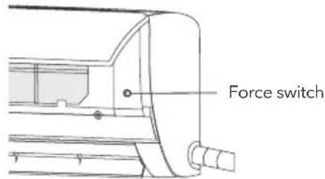
Emergency operation
- If the remote controller is lost or broken, use force switch button to operate the air conditioner.
- If this button is pushed with the unit OFF, the air conditioner will operate in Auto mode.
- If this button is pushed with the unit ON, the air conditioner will stop running.
Airflow direction adjustment
- Use up-down swing and left-right swing buttons on the remote controller to adjust the airflow direction. Refer to the operation manual of the remote controller for detail.
- For models without left-right swing function, the fins has to be moved manually.
Note: Move the fins before the unit is in operation, or your finger might be injured. Never place your hand into the air inlet or outlet when the air conditioner is in operation.
natural_image
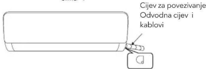
Line drawing of hands installing or adjusting a cylindrical object on a base (no text or symbols)Specific caution
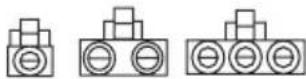
1.Open front panel of the indoor.
2. The connector (as Fig) can not touch the terminal board, and is positioned as shown in Fig.

NAMES OF EACH PART
Indoor unit

Outdoor unit
Note: All the pictures in this manual are just schematic diagrams, the actual is the standard. Plug, WiFi function, Negative-ion function, and vertical and horizontal; swing function both are optional.
CLEAN AND CARE
WARNING!
- Before the cleaning of the air conditioner, it must be shut down and the electricity must be cut off for more than 5 minutes, otherwise there might be the risk of electric shocks.
- Do not wet the air conditioner, which can cause an electric shock. Make sure not to rinse the air conditioner with water under any circumstances.
- Volatile liquids such as thinner or gasoline will damage the air conditioner housing, therefore please clean the housing of air conditioner only with soft dry cloth and damp cloth moistened with neutral detergent.
- In the course of the using, pay attention to cleaning the filter regularly, to prevent the covering of dust which may affect the effect. If the service environment of the air conditioner is dusty, correspondingly increase the number of times of cleaning. After removing the filter, do not touch the fin part of the indoor unit with the finger, and no force to damage the refrigerant pipeline.
Clean the panel
When the panel of the indoor unit is contaminated, clean it gently with a wrung towel using tepid water below 40^ C, and do not remove the panel while cleaning.
Clean the air filter
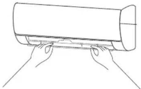
Remove the air filter

natural_image
Line drawing of a cylindrical air conditioner unit with a handle (no text or symbols)
natural_image
Diagram of a car air conditioner unit with cooling fins and airflow direction arrow (no text or labels)- Use both hands to open the panel for an angle from both ends of the panel in accordance with the direction of the arrow.
- Release the air filter from the slot and remove it.
Clean the Air Filter
Use a vacuum cleaner or water to rinse filter, and if the filter is very dirty (for example, with greasy dirt), clean it with warm water (below 45^ C) with mild detergent dissolved in, and then put the filter in the shade to dry in the air.
Mount the Filter
- Reinstall the dried filter in reverse order of removal, then cover and lock the panel.
natural_image
Diagram of a car air conditioner unit with internal grid structure and airflow direction arrow (no text or symbols)
natural_image
Line drawing of a cylindrical air conditioner unit with a curved handle (no text or symbols)Check before use
- Check whether all the air inlets and outlets of the units are unblocked.
- Ceck whether there is blocking in the water outlet of the drain pipe, and immediately clean it up if any.
- Check the ground wire is reliably grounded.
- Check whether the remote control batteries are installed, and whether the power is sufficient.
- Check whether there is damage in the mounting bracket of the outdoor unit, and if any, please contact our local service center.
Maintain after use
- Cut off the power source of the air conditioner, turn off the main power switch and remove the batteries from the remote controller.
- Clean the filter and the unit body.
- Remove the dust and debris from the outdoor unit.
- Check whether there is damage in the mounting bracket of the outdoor unit, and if any, please contact our local service center.

CAUTION!
Do not repair the air conditioner by yourself as wrong maintenance may cause electric shock or fire or explode, please contact the authorized service center and let the professionals conduct the maintenance, and checking the following items prior to contacting for maintenance can save your time and money.
TROUBLESHOOTING
| Phenomenon Troubleshooting | |
| The air conditioner does not work. | There might be power outages. → Wait until power is restored.Power plug may be loose out from the socket. → The plug in the plug tightly.Power switch fuse may blow. → Replace the fuse.The time for timing boot is yet to come. → Wait or cancel the timer settings. |
| The air conditioner can't run after the immediate start-up after it is shut down. | If the air conditioner is turned on immediately after it is turned off, the protective delay switch will delay the operation for 3 to 5 minutes. |
| The air conditioner stops running after it starts up for a while. | May reach the setting temperature. → It is a normal function phenomenon.May be at a defrosting state. → It will automatically restore and run again after defrosting.Shutdown Timer may be set. → If you continue to use, please turn it on again. |
| The wind blows out, but the cooling/ heating effect is not good. | Excessive accumulation of dust on filter, blocking at air inlet and outlet, and the excessively small angle of the louver blades all will affect the cooling and heating effect. → Please clean the filter, remove the obstacles at the air inlet and outlet and regulate the angle of the louver blades.Poor cooling and heating effect caused by doors and windows opening, and unclosed exhaust fan. → Please close the doors, windows, the exhaust fan, etc.Auxiliary heating function is not turned on while heating, which may lead to poor heating effect. → Turn on the auxiliary heating function. (only for models with auxiliary heating function)Mode setting is incorrect, and the temperature and wind speed settings are not appropriate. → Please re-select the mode, and set the appropriate temperature and wind speed. |
| The indoor unit blows out odor. | The air conditioner itself does not have undesirable odor. If there is odor, it may be due to accumulation of the odor in the environment. → Clean the air filter or activate the cleaning function. |
| There is sound of running water during the running of air conditioner. | When the air conditioner is started up or stopped, or the compressor is started up or stopped during the running, sometimes the "hissing" sound of running water can be heard. → This is the sound of the flow of the refrigerant, not a malfunction. |
| A slight “click” sound is heard at the of start-up or shut-down. | Due to temperature changes, panel and other parts will swell, causing the sound of friction. → This is normal, not a fault. |
| The indoor unit makes abnormal sound. | The sound of fan or compressor relay switched on or off.When the defrosting is started or stop running, it will sound. → That is due to the refrigerant flowed to reverse direction. They are not malfunctions.Too much dust accumulation in the air filter of the indoor unit may result in fluctuation of the sound. → Clean the air filters in time.Too much air noise when “Strong wind” is turned on. → This is normal, if feeling uncomfortable, please deactivate the “Strong wind” function. |
| There are water drops over the surface of the indoor unit. | When ambient humidity is high, water drops will be accumulated around the air outlet or the panel, etc. → This is a normal physics phenomenon.Prolonged cooling run in open space produces water drops. → Close the doors and windows.Too small opening angle of the louver blades may also result in water drops at the air inlet. → Increase the angle of the louver blades. |
| During the cooling operation, the indoor unit outlet sometimes will blow out mist. | When the indoor temperature and humidity are high, it happens sometimes.→ This is because the indoor air is cooled rapidly. After it runs for some time, the indoor temperature and humidity will be reduced and the mist will disappear. |

Immediately stop all operations and cut off the power supply, contact our Service center locally in following situations.
- Hear any harsh sound or smell any awful odor during running.
- Abnormal heating of power cord and plug occurs.
- The unit or remote controller has any impurity or water.
• Air switch or leakage protection switch is often disconnected.
NOTICES FOR INSTALLATION

IMPORTANT NOTICES!
- Before installing, please contact with local authorized maintenance center, if unit is not installed by the authorized maintenance center, the malfunction may not solved, due to discommodious contact.
- The air conditioner must be installed by professionals according to the national wiring rules and this manual.
- Refrigerant leak tesf must be made after installation.
• To move and install air conditioner to another place, please contact our local special service center.
Unpacking Inspection
- Open the box and check air conditioner in area with good ventilation (open the door and window) and without ignition source.
Note: Operators are required to wear anti-static devices. - It is necessary to check by professional whether there is refrigerant leakage before opening the box of outdoor machine; stop installing the air conditioner if leakage is found.
- The fire prevention equipment and anti-static precautions shall be prepared well before checking. Then check the refrigerant pipeline to see if there is any collision traces, and whether the outlook 1s good.
Safety Principles for Installing Air Conditioner
- Fire prevention device shall be prepared before installation.
- Keep installing site ventilated.(open the door and window)
- Ignition source, smoking and calling is not allowed to exist in area where R32 refrigerant rocated.
- Anti-static precautions in necessary for installing air conditioner, e.g. wear pure cotton clothes and gloves.
- Keep leak detector in working state during the installation.
- If R32 refrigerant leakage occurs during tfile installation, you shall immediately detect the concentration in indoor environment until it reaches a safe level. If refrigerant leakage affects the performance of the air conditioner, please immediately stop the operation, and the air conditioner must be vacuumed firstly and be returned to the maintenance station for processing.
- Keep electric appliance, power switch, plug, socket, high temperature heat source and high static away from the area underneath sidelines of the indoor unit.
- The air conditioner shall be installed in an accessible location to installation and maintenance, without obstacles that may block air inlets or outlets of indoor/outdoor units, and shall keep away from heat source inflammable or explosive conditions.
- When installing or repairing the air conditioner and the connecting line is not long enough, the entire connecting line shall be replaced with the connecting line of the original specification; extension is not allowed.
- Use new connection pipe, unless re-flaring the pipe.
Requirements For Installation Position
- Avoid places of inflammable or explosive gas leakage or where there are strongly aggressive gases.
- Avoid places subject to strong artificial electric/magnetic fields.
- Avoid places subject to noise and resonance.
- Avoid severe natural conditions (e.g. heavy lampblack, strong sandy wind, direct sunshine or h1gli temperature heat sources).
- Avoid places within the reach of children.
- Shorten the connection between the indoor and outdoor units.
- Select where it is easy to perform service and repair and where the ventilation good.
- The outdoor unit shall not be installed in any way that could occupy an aisle, stairway, exit, fire escape, catwalk or any other public area.
- The outdoor unit shall be installed as far as possible from the doors and windows of the neighbors as well as the green plants.
Installation environment inspection
- Check nameRlate of outdoor unit to make sure whether the refrigerant is R32.
- Check the floor space of the room. The space shall not be less than usable space(sm2) in the specification. The outdoor unit shall be installed at a well-ventilated place.
- Check the surrounding environment of installation site: R32 shall not be installed in the enclosed reserved space of a building.
- When using electric drill to make holes in the wall, check first whether there is pre-buried pipeline for water, electricity and gas.
- It is suggested to use the reserved hole in the roof of tflle walr
Requirements of the mounting structure
- The mounting rack must meet the relevant national or industrial standards in terms of strength with welding and connection areas rustproofed.
- The mounting rack and its load carry surface shall be able to withstand 4 times or above the weight of the unit, or 200kg , whichever is heavier.
- The mounting rack of the outdoor unit shall be fastened with expansion bolt.
- Ensure the secure installation regardless of what type of wall on which it is installed, to prevent potential dropping that could hurt people.
Electrical Safety Requirements
- Be sure to use the rated voltage and air conditioners dedicated circuit for the power supply, and the power cord diameter must meet the national requirements.
- When the maximum current of air conditioner is ≥ 16A , it must use the air switch or leakage protection switch equipped with protection devices.
- The operating range is 90%-110% of the local rated voltage. But insufficient power supply malfunction, electrical shock, or fire. If the voltage instability, proposed to increase the voltage regulator.
- The minimum clearance between the air conditioner and the combustibles is 1.5 m.
- The interconnection cord connect the indoor and outdoor units. You must first choose the right cable size before preparing it for connection.
- Cable Types: Outdoor Power Cable: H07RN-F or H05RN-F; Interconnection cord: H07RN-F or H05RN-F;
- Minimum Cross-Sectional Area of Power cable and interconnection cord.
North America Other regions
| Appliance Amps (A) | AWG |
| 10 18 | |
| 13 16 | |
| 18 14 | |
| 25 12 | |
| 30 10 | |
| 40 8 |
| Rated Current of Appliance (A) | Nominal Cross-Sectional Area ( mm^2 ) |
| >3 and ≤ 6 0.75 | |
| >6 and ≤10 1 | |
| >10 and ≤16 1.5 | |
| >10 and ≤16 2.5 | |
| >10 and ≤16 4 | |
| >10 and ≤16 6 |
- The size of the interconnection cord, power cable, fuse, and switch needed is determined by the maximum current of the unit. The maximum current is indicated on the nameplate located on the side panel of the unit. Refer to this nameplate to choose the right cable, fuse, or switch.
- Note: Core number of cable refer to the detailed wiring diagram adhered on the unit which you purchased.
Requirements for operations at raised height
- When carrying out installation at 2m or higher above the base level, safety belts must be worn and ropes of sufficient strength be securely fasten to the outdoor unit, to prevent falling that could cause personal injury or death as well as property loss.
Grounding Requirements
- The air conditioner is the class I electrical appliance and must ensure a reliable grounding.
- Do not connect the grounding wire to a gas pipe, water pipe, lightning rod, telephone line, or a circuit poorly grounded to the earth.
- The grounding wire is specially designed and shall not be used for other purpose, nor shall it be fastened with a common tapping screw.
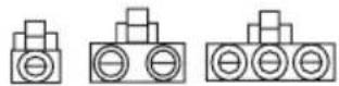
- Interconnection cord diameter should be recommended as per instruction manual, and with type O terminal that meet local standards (internal diameter of type O terminal needs to match the screw size of the unit, no more than 4.2mm). After installation, check the screws whether have been fixed effectively, and there is no risk of loosening.
Others
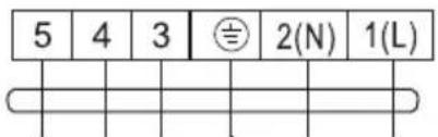
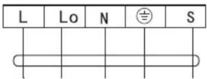
- The connection method of the air conditioner and the power cord and the interconnection method of each independent element shall be subject to the wiring diagram affixed to the machine.
- The model and rating value of the fuse shall be subject to the silkscreen on corresponding controller or fuse sleeve.
Packing list
Packing list of the indoor unit
| Name Quantity Unit | ||
| Indoor Unit 1 Set | ||
| Remote Controller 1 PC | ||
| Batteries (7#) 2 PC | ||
| Owner's manual 1 Set | ||
| Drain pipe 1 PC |
Packing list of the outdoor unit
| Name Quantity Unit | ||
| Outdoor Unit 1 Set | ||
| Connecting pipe (optional) | 2 PC | |
| Plastic Strap 1 ROLL | ||
| Pipe Protection Ring | 1 | PC |
| Luting (putty) (optional) | 1 | PACKET |
Note: All accessories shall be subject to actual packaging material, and if there is any difference, please understand.
INSTALL INDOOR UNIT
Dimension drawing of indoor unit installation
Mounting plate
- The wall for installation of the indoor unit shall be hard and firm, so as to prevent vibration.
- Use the "+" type screw to fasten the peg board, horizontally mount the peg board on the wall, and ensure the lateral horizontal and longitudinal vertical.
- Pull the peg board by hand after the installation, to confirm whether it is solid.

natural_image
Technical line drawing of a mechanical assembly with mounting brackets and fasteners (no text or symbols)Wall-through Hole
- Make a hole with an electric hammer or a water drill at the predetermined position on the wall for piping, which shall slant outwardly by 5^-10^ .
- To protect the piping and the cables from being damaged running through the wall, and from the rodents that may inhabit in the hollow wall, a pipe protecting ring shall be installed and sealed with putty.
Note: Usually, the wall hole is 60mm 80mm . Avoid preburied power wire and hard wall when making the hole.

Route of Pipeline
- Depending on the position of the unit, the piping may be routed sideways from the left or the right (Fig 1), or vertically from the back (Fig 2) (depending on the pipe length of the indoor unit). In the case of sideway routing, cut off the outlet cutting stock of the opposite side.
Fig 1

Fig 2
Drain pipe connection
- Remove the fixed part to pull out pipe of indoor machine from the case. Screw the hexagon nut in the left of the joint to the end with your hand.
- Connect the connecting pipe to the indoor unit: Aim at the pipe center, tighten the Taper nut with fingers, and then tighten the Taper nut with a torque wrench, and the direction is shown in diagram on the right. The torque used is shown in the following table.
Note: Carefully check if there is any damage of joints before installation.
The joints shall not be reused, unless after re-flaring the pipe.
Tightening torque table
| The size of pipe (mm) Torque (Nm) | |
| 6/ 6.351588 | |
| 9/ 9.523540 | |
| 12/ 12.74560 | |
| 15.887378 | |
| 19.057580 | |

Wrap the Piping
- Use the insulation sleeve to wrap the joint part the indoor unit and the connection pipe, and then use insulating material to pack and seal insulation pipe, to prevent generation of condensate water on the joint part.
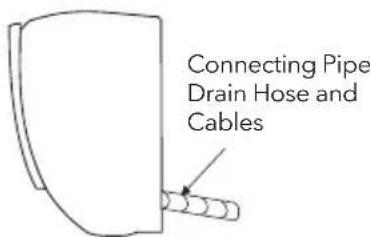
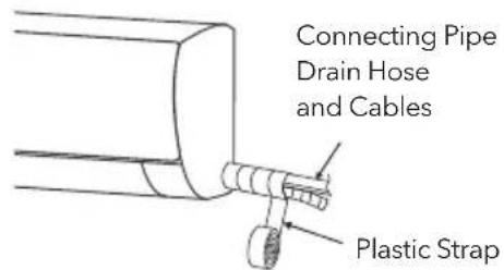
- Connect the water outlet with drain pipes, and make the connection pipe, cables, and the drain hose straight.
- Use plastic cable ties to wrap the connecting pipes, cables and drain hose. Run the pipe sloping downward.
Fixing the Indoor Unit
- Hang the indoor unit on the peg board, and move the unit from left to right to ensure that the hook is properly positioned in the peg board.
- Push toward the lower left side and the upper right side of the unit toward the peg board, until the hook is embedded in the slot and makes a "click" sound.

natural_image
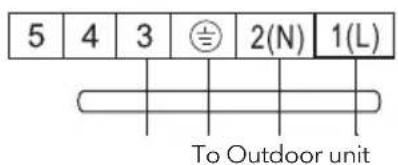
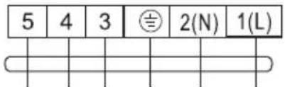
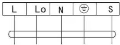
Two diagrams showing hand positioning of a mechanical component with a tool, no text or symbols presentWiring diagram
- If your air conditioner is provided with interconnection cord, the wiring of the indoor unit is connected in the factory, there is no need of connection.
- If the interconnection cord is not provided, connection is needed in accordance with the
After installation, check:
- The screws whether have been fixed effectively, and there is no risk of loosening.
- Connector of display board whether put in the right place and do not touch the terminal board.
- Control box cover whether cover tightly.
Constant speed
Variable speed
Connector


NOTE:
- This manual usually includes the wiring mode for the different kind of A/C. We cannot exclude the possibility that some special type of wiring diagrams are not included.
- The diagram are for reference only. If the entity is difference with this wiring diagram, please refer to the detailed wiring diagram adhered on the unit which you purchased.
INSTALL OUTDOOR UNIT GAS R32
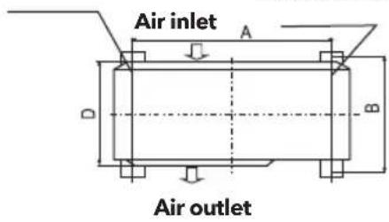
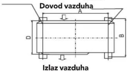
Dimension drawing of outdoor unit installation

natural_image
Technical line drawing of a front-end air duct fan with labeled dimensions H and L (no text or symbols beyond labels)
| Outdoor Dimensions (mm)LxHxD | Mounting Dimensions | |
| Distance A (mm) | Distance B (mm) | |
| 735x475x250 453 280 | ||
| 790x520x280 508 314 | ||
| 848x670x354 544 354 | ||
Left
installation feet
Right
installation feet
Install the connection pipe
Connect the Outdoor Unit with Connecting Pipe:
Aim the counter-bore of the connecting pipe at the stop valve, and tighten the Taper nut with fingers. Then tighten the Taper nut with a torque wrench. When prolonging the piping, extra amount of refrigerant must be added so that the operation and performance of the air conditioner will not be compromised.
| Piping length | Amount of refrigerant to be added | Amount of refrigerant for the unit | |
| 5M Not needed | |||
| 5-15M | CC12000Btu 15g/m 1 kg | ||
| CC18000Btu 30g/m 2 kg | |||

Note: 1. This table is for reference only.
- The joints shall not be reused, unless after re-flaring the pipe.
- After installation, check the stop valve cover whether be fixed effectively.
INSTALL OUTDOOR UNIT
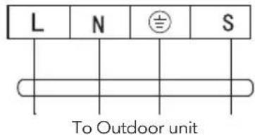
Wiring Connection
- Loosen the screws and remove E-parts cover from the unit.
- Connect the cables respectively to the corresponding terminals of the terminal board of the outdoor unit (see the wiring diagram), and if there are signals connected to the plug, just conduct butt joint.
- Ground wire: Remove the grounding screw out of the electric bracket, cover the grounding wire end onto the grounding screw and screw it into the grounding hole.
- Fix the cable reliably with fasteners (Pressing board).
- Put the E-parts cover back in its original place and fasten it with screws.

natural_image
Technical line drawing of a device rear panel with internal components and wiring (no text or symbols)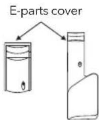
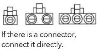
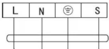
Wiring diagram

Connector

If there is a connector, connect it directly.
Note:
- This manual usually includes the wiring mode for the different kind of A/C. We cannot exclude the possibility that some special type of wiring diagrams are not included.
- The diagram are for reference only. If the entity is difference with this wiring diagram, please refer to the detailed wiring diagram adhered on the unit which you purchased.
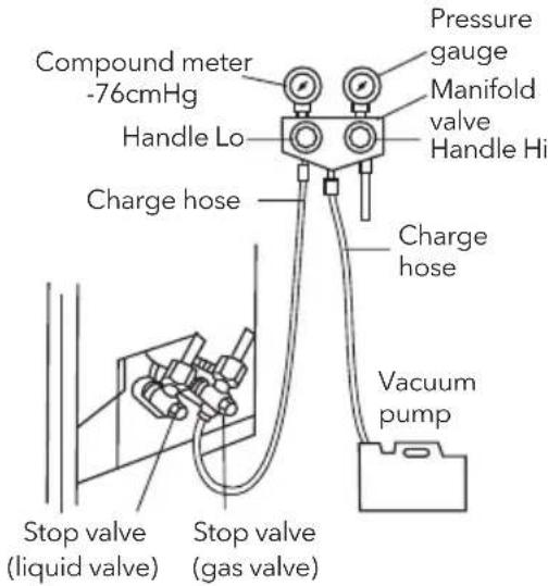
Vacuuming (Gas R32)
Exclusive R32 refrigerant pump must be used in making R32 refrigerant vacuum.
Before working on the air conditioner, remove the cover of the stop valve(gas and liquid valves)and be sure to retighten it afterward.(to prevent the potential air leakage).
- To prevent air leakage and spilling tighten all connecting nut of all flare tubes.
- Connect the stop valve, charge hose, manifold valve, and vacuum pump.
- Fully open the handle Lo of the manifold valve and apply vacuum for at least 15 minutes and check that the compound vacuum gauge reads -0.1MPa (-76cmHg).
- After applying vacuum, fully open the stop valve with a hex wrench.
- Check that both indoor and outdoor connections are free of air leakage.
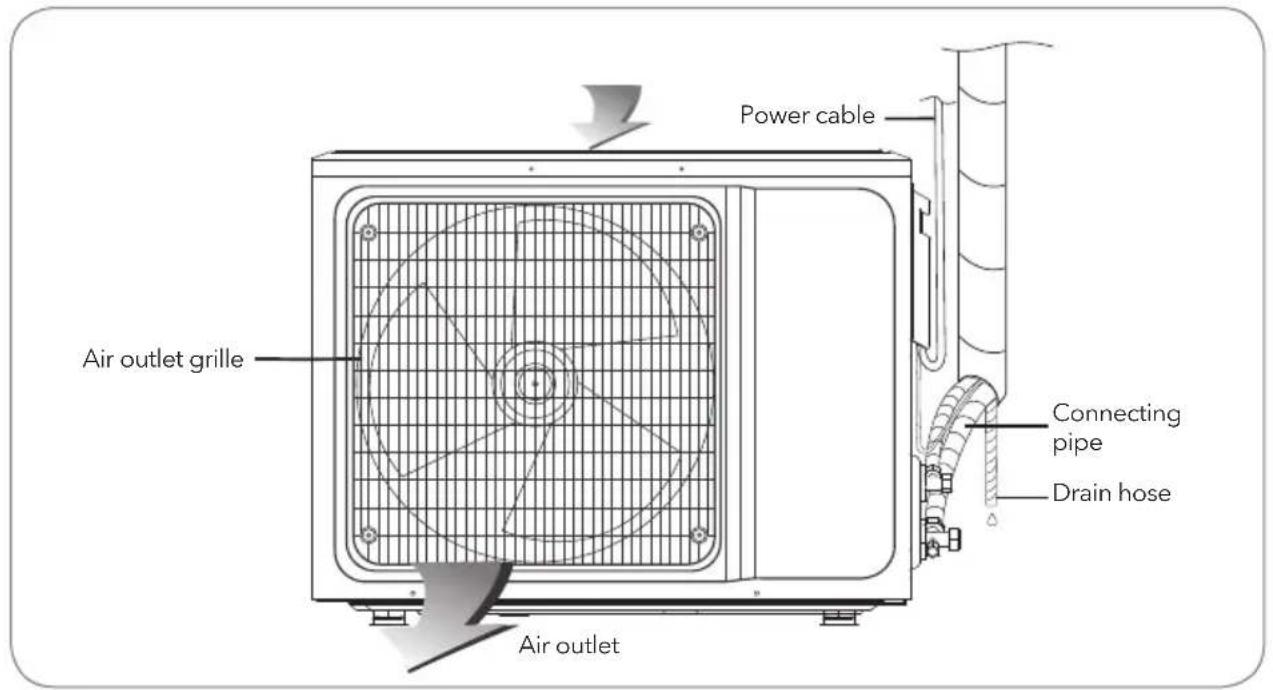
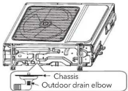
Outdoor condensation drainage (Heat pump type only)
When the unit is heating, the condensing water and defrosting water can be out reliably through the drain house.
Installation:
Install the outdoor drain elbow in 25 hole on the base plate, and joint the drain hose to the elbow, so that the waste water formed in the outdoor unit can be drained out to a proper plate.
CHECK AFTER INSTALLATION AND TEST OPERATION
Check after installation
Electrical Safety Check
- If the supply voltage is as required.
- If there is any faulty or miss connection in each of the power, signal and grounding wires.
- If the grounding wire of the air conditioner is securely grounded.
Installation Safety Check
- If the installation is secure.
- If the water drain is smooth.
- If the wiring and piping are correctly installed.
- Check that no foreign matter or tools are left inside the unit.
- Check the refrigerant pipeline is protected well.
Leak test of the refrigerant
Depending on the installation method, the following methods may be used to check for suspect leak, on areas such as the four connections of the outdoor unit and the cores of the cut-off valves and t-valves:
- Bubble method: Apply of spray a uniform layer of soap water over the suspected leak spot and observe carefully for bubble.
- Instrument method: Checking for leak by pointing the probe of the leak detector according to the instruction to the suspect points of leak.
Note: Make sure that the ventilation is good before checking.
Test Operation
- Verify that all piping and connection cables are well connected.
- Confirm that the values at the gas side the liquid-side are fully open.
- Connect the power cord to an independent power socket.
• Install batteries in remote control.
Note: Make sure that the ventilation is good before testing.
Test Operation method:
- Turn on the power and push the ON/OFF switch button of the remote controller to start the air conditioner.
- Select COOL, HEAT (not available on cool-only models), SWING and other operation modes with the remote controller and see if the operation is ok.
MAINTENANCE NOTICE
Attention:
For maintenance or scrap, please contact authorized service centers. Maintenance by unqualified person may cause dangers. Feed air conditioner with R32 refrigerant, and maintain the air conditioner in strictly accordance with manufacturer's requirements. The chapter is mainly focused on special maintenance requirements for appliance with R32 refrigerant. Ask repairer to read after-sales technical service handbook for detailed information.
Qualification requirements of maintenance personnel
- Special training additional to usual refrigerating equipment repair procedures is required when equipment with flammable refrigerants is affected. In many countries, this training is carried out by national training organisations that are accredited to teach the relevant national competency standards that may be set in legislation. The achieved competence should be documented by a certificate.
- The maintenance and repair of the air conditioner must be conducted according to the method recommended by the manufacturer. If other professionals are needed to help maintain and repair the equipment, it should be conducted under the supervision of individuals who have the qualification to repair AC equipped with flammable refrigerant.
Inspection of the Site
Safety inspection must be taken before maintaining equipment with R32 refrigerant to make sure the risk of fire is minimized. Check whether the place is well ventilated, whether anti-static and fire prevention equipment is perfect. While maintaining the refrigeration system, observe the following precautions before operating the system.
Operating Procedures
-
General work area: All maintenance staff and others working in the local area shall be instructed on the nature of work being carried out. Work in confined spaces shall be avoided. The area around the workspace shall be sectioned off. Ensure that the conditions within the area have been made safe by control of flammable material.
-
Checking for presence of refrigerant: The area shall be checked with an appropriate refrigerant detector prior to and during work, to ensure the technician is aware of potentially toxic or flammable atmospheres. Ensure that the leak detection equipment being used is suitable for use with all applicable refrigerants, Le.non-sparking, adequately sealed or intrinsically safe.
-
Presence of fire extinguisher: If any hot work is to be conducted on the refrigeration equipment or any associated parts, appropriate fire extinguishing equipment shall be available to hand. Have a dry powder or CO2 fire extinguisher adjacent to the charging area.
-
No ignition sources: No person carrying out work in relation to a refrigeration system which involves exposing any pipe work shall
use any sources of ignition in such a manner that it may lead to the risk of fire or explosion. All possible ignition sources, including cigarette smoking, should be kept sufficiently far away from the site of installation, repairing, removing and disposal, during which refrigerant can possibly be released to the surrounding space. Prior to work taking place, the area around the equipment is to be surveyed to make sure that there are no flammable hazards or ignition risks.
'No Smoking' signs shall be displayed.
- Ventilated Area(open the door and window):
Ensure that the area is in the open or that it is adequately ventilated before breaking into the system or conducting any hot work. A degree of ventilation shall continue during the period that the work is carried out. The ventilation should safely disperse any released refrigerant and preferably expel it externally into the atmosphere.
- Checks to the refrigeration equipment:
Where electrical components are being changed, they shall be fit for the purpose and to the correct specification. At all times the manufacturer's maintenance and service guidelines shall be followed. If in doubt, consult the manufacturer's technical department for assistance. The following checks shall be applied to installations using flammable refrigerants:
- The charge size is in accordance with the room size within which the refrigerant containing parts are installed.
- The ventilation machinery and outlets are operating adequately and are not obstructed.
- If an indirect refrigerating circuit is being used, the secondary circuit shall be checked for the presence of refrigerant.
- Refrigeration pipe or components are installed in a position where they are unlikely to be exposed to any substance which may corrode refrigerant containing components, unless the components are constructed of materials which are inherently resistant to being corroded or are suitably protected against being so corroded.
- Checks to electrical devices:
Repair and maintenance to electrical components shall include initial safety checks and component inspection procedures. If a fault exists that could compromise safety, then no electrical supply shall be connected to the circuit until it is satisfactorily dealt with. If the fault cannot be corrected immediately but it is necessary to continue operation, an adequate temporary solution shall be used. This shall be reported to the owner of the equipment so all parties are advised.
Initial safety checks shall include:
- That capacitors are discharged: this shall be done in a safe manner to avoid possibility of sparking.
- That no live electrical components and wiring are exposed while charging, recovering or purging the system.
- Keep continuity of earthing.
Inspection of Cable
Check the cable for wear, corrosion, overvoltage, vibration and check if there are sharp edges and other adverse effects in the surrounding environment. During the inspection, the impact of aging or the continuous vibration of the compressor and the fan on it should be taken into consideration.
Leakage check of R32 refrigerant
Note: Check the leakage of the refrigerant in an environment where there is no potential ignition source. No halogen probe (or any other detector that uses an open flame) should be used.
Leak detection method:
For systems with refrigerant R32, electronic leak detection instrument is available to detect and leak detection should not be conducted in environment with refrigerant. Make sure the leak detector will not become a potential source of ignition, and is applicable to the measured refrigerant. Leak detector shall be set for the minimum ignitable fuel concentration (percentage) of the refrigerant. Calibrate and adjust to proper gas concentration (no more than 25%) with the used refrigerant.
The fluid used in leak detection is applicable to most refrigerants. But do not use chloride solvents to prevent the reaction between chlorine and refrigerants and the corrosion of copper pipeline.
If you suspect a leak, then remove all the fire from the scene or put out the fire.
If the location of the leak needs to be welded, then all refrigerants need to be recovered, or, isolate all refrigerants away from the leak site (using cut-off valve). Before and during the welding, use OFN to purify the entire system.
Removal and Vacuum Pumping
- Make sure there is no ignited fire source near the outlet of the vacuum pump and the ventilation is well.
-
Allow the maintenance and other operations of the refrigeration circuit should be carried out according to the general procedure, but the following best operations that the flammability is already taken into consideration are the key. You should follow the following procedures:
-
Remove the refrigerant.
- Decontaminate the pipeline by inert gases.
- Evacuation.
- Decontaminate the pipeline by inert gases again.
-
Cut or weld the pipeline.
-
The refrigerant should be returned to the appropriate storage tank. The system should be blown with oxygen free nitrogen to ensure safety. This process may need to be repeated for several times. This operation shall not be carried out using compressed air or oxygen.
-
Through blowing process, the system is charged into the anaerobic nitrogen to reach the working pressure under the vacuum state, then the oxygen free nitrogen is emitted to the atmosphere, and in the end, vacuumize the system. Repeat this process until all refrigerants in the system is cleared. After the final charging of the anaerobic nitrogen, discharge the gas into the atmosphere pressure, and then the system can be welded. This operation is necessary for welding the pipeline.
Procedures of Charging Refrigerants
As a supplement to the general procedure, the following requirements need to be added:
- Make sure that there is no contamination among different refrigerants when using a refrigerant charging device. The pipeline for charging refrigerants should be as short as possible to reduce the residual of refrigerants in it.
- Storage tanks should remain vertically up.
- Make sure the grounding solutions are already taken before the refrigeration system is charged with refrigerants.
- After finishing the charging (or when it is not yet finished), label the mark on the system.
- Be careful not to overcharge refrigerants.
Scrap and Recovery
Scrap:
Before this procedure, the technical personnel shall be thoroughly familiar with the equipment and all its features, and make a recommended practice for refrigerant safe recovery. For recycling the refrigerant, shall analyze the refrigerant and oil samples before operation. Ensure the required power before the test.
- Be familiar with the equipment and operation.
- Disconnect power supply.
- Before carrying out this process, you have to make sure:
- If necessary, mechanical equipment operation should facilitate the operation of the refrigerant tank.
- All personal protective equipment is effective and can be used correctly.
- The whole recovery process should be carried out under the guidance of qualified personnel.
- The recovering of equipment and storage tank should comply with the relevant national standards.
- If possible, the refrigerating system should be vacuumized.
- If the vacuum state can't be reached, you should extract the refrigerant in each part of the system from many places.
- Before the start of the recovery, you should ensure that the capacity of the storage tank is sufficient.
- Start and operate the recovery equipment according to the manufacturer's instructions.
- Don't fill the tank to its full capacity (the liquid injection volume does not exceed 80% of the tank volume).
- Even the duration is short, it must not exceed the maximum working pressure of the tank.
- After the completion of the tank filling and the end of the operation process, you should make sure that the tanks and equipment should be removed quickly and all closing valves in the equipment are closed.
- The recovered refrigerants are not allowed to be injected into another system before being purified and tested.
Note: The identification should be made after the appliance is scrapped and refrigerants are evacuated. The identification should contain the date and endorsement. Make sure the identification on the appliance can reflect the flammable refrigerants contained in this appliance.
Recovery:
- The clearance of refrigerants in the system is required when repairing or scrapping the appliance. It is recommended to completely remove the refrigerant.
- Only a special refrigerant tank can be used when loading the refrigerant into the storage tank. Make sure the capacity of the tank is appropriate to the refrigerant injection quantity in the entire system. All tanks intended to be used for the recovery of refrigerants should have a refrigerant identification (i.e. refrigerant recovery tank). Storage tanks should be equipped with pressure relief valves and globe valves and they should be in a good condition. If possible, empty tanks should be evacuated and maintained at room temperature before use.
- The recovery equipment should be kept in a good working condition and equipped with equipment operating instructions for easy access. The equipment should be suitable for the recovery of R32 refrigerants. Besides, there should be a qualified weighting apparatus which can be normally used. The hose should be linked with detachable connection joint of zero leakage rate and be kept in a good condition. Before using the recovery equipment, check if it is in a good condition and if it gets perfect maintenance. Check if II electrical components are sealed to prevent the leakage of the refrigerant and the fire caused by it. If you have any question, please consult the manufacturer.
- The recovered refrigerant shall be loaded in the appropriate storage tanks, attached with a transporting instruction, and returned to the refrigerant manufacturer. Don't mix refrigerant in recovery equipment, especially a storage tank.
- The space loading R32 refrigeration can't be enclosed in the process of transportation. Take anti electrostatic measures if necessary in transportation. In the process of transport, loading and unloading, necessary protective measures must be taken to protect the air conditioner to ensure that the air conditioner is not damaged.
- When removing the compressor or clearing the compressor oil, make sure the compressor is pumped to an appropriate level to ensure that there is no residual R32 refrigerants in the lubricating oil. The vacuum pumping should be carried out before the compressor is returned to the supplier. Ensure the safety when discharging oil from the system.
REMOTE CONTROLLER INSTRUCTIONS
- Read this "instructions" carefully so that you can use the air-conditioner safely and correctly.
- Take good care of the "instructions" so that it can be referred to at any time.
Attention
- Aim the remote controller towards the receiver on the airconditioner.
- The remote controller should be within 8 meters away from the receiver.
- No obstacles between the remote controller and receiver.
- Do not drop or throw the remote controller.
- Do not put the remote controller under the forceful sun rays or heating facilities and other heating sources.
- Use two 7# batteries, do not use the electric batteries.
- Take the batteries out of remote controller before stop its using for long.
- When the noise of transmitting signal can't be heard indoor unit or the transmission symbol on the display screen doesn't flare, batteries need be replaced.
- If reset phenomenon occurs on pressing the button of the remote controller, the electric quantity is deficient and new batteries need to be substituted.
- The waste battery should be disposed properly.
Note:
- The picture is general remote controller, contains almost all of the function buttons. They may be slightly different from material abject(depend on model).
- All the figures above are the displays after being initially electrified or re-electrified after power off. In actual operations, the remote controller screen displays related items only.
- The cooling only units don't have the function of heating or electric heating. When the remote controller turns to such function buttons, the units will not result such effect. Please don't turn the remote controller to such buttons.
Instructions of remote controller

1. The icon meaning of remote controller
- The remote controller is equipped with 11 buttons, and the LCD.
- At the first power on, the LCD of the remote controller displays all the icons first and then enters the standby state, displaying only the mode icon.
- Introduction of LCD screen icon:
- Mode display: automatic △, cooling *dehumidification , fan
- Temperature display: 88.8 displays temperature, which range between 16\~32°C or 61\~90°F
- Wind speed display: ✦---- means wind speed.
- Swinging display: means external pendulum wind. means internal pendulum wind.
- Timer display: ON means TIME ON. means TIME OFF.
- Other display: means sleep; means TURBO; means ECO; means electric heating; means lock; means lamplight.
2. Button function of remote controller
ON/OFF:
When pressing this key, the remote controller switches by "on, off, on" circularly.
Mode:
- When pressing this key, the remote controller switches by "automatic, cooling, dehumidification, fan, heating, automatic" circularly.
- In dehumidification mode, the setting temperature of the internal machine is 25 degree C. The remote
controller does not display the setting temperature and is not adjustable. The internal pendulum wind stays unchanged according to the state before switching, but the external pendulum wind is forced to close.
Temperature reduction -
- Temperature setting: when pressing this key, the setting temperature will be reduced by "32°C, 31 °C, ……, 17°C, 16°C". (When pressing this key in dehumidification and fan mode, the temperature will not change).
- Keep pressing will continuously change the temperature.
Temperature addition +
- Temperature setting: when pressing this key, the setting temperature will be added by "16°C, 17°C, ……, 31°C, 32°C", (When pressing this key in dehumidification and fan mode, the temperature will not change).
- Keep pressing will continuously change the temperature.
Up and down swinging (External pendulum wind)
- Pressing this key in the dehumidification mode, the external pendulum wind is forced to close.
- Pressing this key in the other modes, the external pendulum switches by "swing, fixed wind, swing" circularly.
Left and right swinging (Internal pendulum wind):
- Pressing this key in the dehumidification mode, the internal pendulum wind stays unchanged according to the state before switching.
- Pressing this key in the other modes, the internal pendulum switches by "swing, stop, swing" circularly.
FAN:
- When the first power on, the remote controller is set to the automatic wind speed by default. In dehumidification mode, the wind speed is fixed to low wind and is not adjustable. By pressing the wind speed key, there is no response to the remote controller.
- Pressing this key in the other modes, the wind speed switches by "automatic wind speed, low speed, middle speed, high speed, automatic wind speed" circularly.pendulum switches by "swing, stop, swing" circularly, high speed, automatic wind speed" circularly.
Timer:
- Under the shutdown state, press this key to set the opening time, range from 1 hour to 24 hour.
- Under the boot state, press this key to set the shutdown time, range from 1 hour to 24 hour.
- The timing time is according to the cycle of "1h, 2h,……, 23h, 24h, cancel, 1h".
- Exit timing adjustment after 3 seconds without key pressing.
TURBO:
- Extension code remote controller has the effect. The remote controller is no TURBO by default, and the TURBO key will not work in automatic mode, dehumidification mode and fan mode.
- Pressing this key in the cooling or heating mode, the TURBO mode switches between opening and closing. When in the TURBO mode, it still displays the wind speed. Switching mode or entering sleep function will close TURBO mode.
- If the air conditioner has TURBO mode, pressing this key, the remote controller still displays current windshield, and indoor unit runs with the highest wind.
ECO:
- The remote controller is no ECO by default, and the ECO key will not work in automatic mode, dehumidification mode and fan mode.
- Pressing this key in the cooling or heating mode, the ECO mode switches between opening and closing. When in the ECO mode, the setting temperature is set to 26^ C ( 79^ F) and other settings are unchanged. If closing ECO mode, the remote controller will recover to the setting before opening ECO mode. Switching mode will close ECO mode.
SLEEP:
- Pressing this key in the modes except of the fan mode, the sleep function switches between opening and closing. Switching mode will cancel sleep function.
- When pressing this key, the wind speed is automatically switched to low wind. However, the wind speed can be adjusted according to the wind speed key (except of the dehumidification mode).
LIGHT
- When the first power on, there is no lamplight by default. Pressing Fan key 3S force to turn off or turn on the lamplight. Decide whether to have this function according to the actual model.
LOCK
- There is no lock by default. Pressing Sleep key 3S, the lock function switches between opening and closing.
Electricheating (Optional)
- Pressing Timer key 3S, the electric heating function switches between opening and closing.
- It only works in heating mode, switch heating mode, the default on.
CLEAN (Optional)
- The remote controller is no CLEAN by default. Pressing TURBO key 3S, the CLEAN function switches between opening and closing. Decide whether to have this function according to the actual model.
IFEEL (Optional)
- The remote controller is no IFEEL by default. Pressing ECO key 3S, the IFEEL function switches between opening and closing.Decide whether to have this function according to the actual model.
Distribution function
- Press the TURBO 10 times or more continuously within 20 seconds until the lamplight displays A P. Decide whether to have this function according to the actual model.
Combinatorial key: "Mode + ECO"
- On the shutdown interface, press the combinatorial key on the remote controller for 5 seconds to enter the address setting interface, the address displayed by the remote controller after entering is the address retained last time. When controlling the wired controller by remote controller, press the mode key to query the address, querying address remote controller interface does not display, the wired controller can display.
- At the address setting interface, press the temperature addition or reduction to adjust the setting address, and it ranges from 00→1→...→99→00. Press the ON / OFF key to enter the sending state and send the address setting code.
- Press the combinatorial key on the remote controller for 5 seconds to exit the address setting interface. If there is no key pressing associated with address setting for more than 30 minutes, the remote controller will exit the address setting interface.
Combinatorial key: "TIMER" + "SLEEP"(Optional)
- Pressing the combinatorial key on the remote controller for 3 seconds, the ionizer function switches between opening and closing.
- The ionizer function works in any mode. When the ionizer function is ON, if turn off the unit, the ionizer function will be closed at same time and it is still closed after turning on the unit again.
UPOZORENJE
Upozorenje: Ovaj klima uređaj koristi R32 zapaljivo rashladno sredstvo.
natural_image
Line drawing of hands installing or adjusting a cylindrical component (no text or symbols)Posebna opreznost
natural_image
Line drawing of a cylindrical air conditioner unit with a handle (no text or symbols)
natural_image
Diagram of a car air conditioner unit with cooling fins and airflow direction arrow (no text or labels)- Koristite obje ruke da biste otvorili panel bočno sa obe strane u pravcu koji pokazuje strelica.
- Oslobodite filter za vazduh i uklonite ga.
Očistite filter za vazduh
Koristite usisivač ili vodu za ispiranje filtera, a ako je filter jako prljav (npr. masna prljavština), očistite ga toplom vodom (ispod 45°C) sa blagim rastvorom deterdženta, a zatim ostavite filter da se osuši na vazduhu.
Postavite filter
- Vratite osušeni filter obrnutim redosledom od uklanjanja, zatim zatvorite panel.

natural_image
Diagram of a car air conditioner unit with internal grid structure and airflow direction arrow (no text or labels)
natural_image
Line drawing of a cylindrical air conditioner unit with a curved handle (no text or symbols)natural_image
Technical line drawing of a mechanical assembly with mounting brackets and mounting holes (no text or symbols)Zidni otvor
- Napravite otvor električnim čekićem ili vodenom bušilicom na unaprijed određenom položaju na zidu za cjevovode, koji će nagnuti prema van za 5° -10°.
- Da bi se cjevovode i kablove koji prolaze kroz zid zaštitili od oštećenja, kao i od glodara koji se mogu naseliti u šupljem zidu, ugradiće se zaštitni prsten za cijev i zapečatiti cementom.
Napomena: Obično zidni otvor je ∅>60mm \~ ∅>80mm. Izbegavajte ranije postavljene električnu žicu i tvrdi zid prilikom izrade otvora.

Put cjevovoda
- U zavisnosti od položaja jedinice, cjevovodi mogu biti postavljeni postrance sa lijeve ili desne strane (slika 1), ili vertikalno od pozadi (slika 2) (zavisno od dužine cijevi unutrašnje jedinice). U slučaju bočnog polaganja, odseći reznu ploču na suprotnoj strani.

natural_image
Two hand-drawn diagrams showing a cable being inserted into a wall, with no text or symbols present.Dijagram el. instalacija
- Ako je vaš klima uređaj opremljen kablom za povezivanje, kablovi unutrašnje jedinice su fabrički povezani, nema potrebe za povezivanjem.
- Ako kabl za povezivanje nije obezbijeden, potrebno je povezivanje
Nakon instalacije, provjerite:
- Da li su šrafovi dobro pričvršćeni, i nema opasnosti od otpuštanja.
- Priključak ploče za prikazivanje bez obzira da li je postavljen na pravo mjesto i ne dodiruje ploču terminala.
- Da li je poklopac kontrolne kutije dobro zatvoren.
Konstantna brzina

Spoljašna jedinica
Spoljašna jedinica
Promenljiva brzina

Spoljašna jedinica
Spoljašna jedinica
Konektor
Ako postoji konektor, povežite direktno.
NAPOMENA:
Ovaj priručnik obično uključuje režim instalacija za različite vrste klima uređaja. Ne možemo isključiti mogućnost da neki posebni tipovi dijagrama instalacija nisu uključeni.
natural_image
Technical line drawing of a four-blade air fan inside a rectangular housing, with dimension labels H and L (no text or symbols on the fan itself)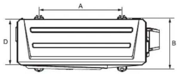
| Veličina spoljašnje jedinice (mm)LxHxD | Mounting Dimensions | |
| Distance A (mm) Distance B (mm) | ||
| 735x475x250 453 280 | ||
| 790x520x280 508 314 | ||
| 848x670x354 544 354 | ||
Leva instalaciona strana
Desna instalaciona strana
PROVJERANAKONINSTALACIJEIPROBNIRAD
Čapljina, HIPEX, Gabela bb, 063/323-015
Čelić, MS KUCALOVIĆ, Meraje 6, 061-290-838
Čitluk, MALIŠIĆ MP, Tromeda bb, 063/449-953
Derventa, COMTECH STR., Cara Lazara bb, 053/311-540
Doboj, KING, Vojvode Mišića 9, 053/203-333
Doboj, Zecom Plus, V.Mišića L3, 053 203 930
Doboj, HIDROTERM, Lipac bb, 066/219-085
Goražde, TEHNIKA, Mravinjac bb, 061/156-046
Gračanica, DŽINDO EL., Stubo bb, 061/843-888; 035/703-394
Gradačac, HIDO EL.SERVIS, Željeznička 20, 061/103-900, 061/178-431
Gradiška, FRIGOELEKTRO SERVIS ZR, 5. Kozarske brigade 11, 066-488-479
Gradiška, KOMING, Vidovdanska bb, 051/814-864
Gradiška, KLIMATRON, Kneza Lazara 2, 051/921-129; 065/938-998
Gradiška, KGH Projektovanje, Agroind. zona 12B; Nova Topola, 066/706-911
Grude, DIGITEHNIK, Dr. Franje Tuđmana 18, 063-050-555; 063/437-107
Grude, TEHNODOM, Blage Zadre 9, 039/662-083
Ilijaš, Mirza, Ilijaš, 061/011-614; 066/811-104
AUTORIZOVANI SERVISI BiH
Jajce, SMART, Trgovački centar bb, 061/109-941; 062/889-103
Kakanj, DELTA THERM, Donji Banjevac bb, 061/871-359
Kalesija, MAGIC VISION, Kalesijskih brigada 15, 061/284-362
Konjic, ELEKTRON, Varda 30. , 061/153-988; 036/730-654
Konjic, FRIGOTEHNIKA, Šunji 45, 061/164-849
Konjic, AC-MONT, Luka bb, 061/687-484
Kotor Varoš, GL SERVIS, Novo naselje bb, 051/922-895, 065/587-740
Kozarska Dubica, ELMONT, Vojvode Petra Bojovića bb, 052/425-333; 066/916-592
Ključ, TNG, Otoke bb, 037/684-701, 061/261-439
Lukavac, IMEL, Skendera Kulenovića bb, 080/020-405
Lukavac, PC ONER, Branilaca Bosne bb, 061/650-427
Maglaj, PC BIRO SHOP, Viteška 8, 061/783-656, 032/604-330
Maglaj, NEXT MEDIA, Viteška bb, 032/605-252
Modriča, PRODEX, Cara Lazara 35, 053/820-891
Mostar, ELEKTRO PROFING, Zalik - Put za Velež bb, 061/383-050
Mostar, KATARINA, Ante Starčevića 48, 036/349-020
Mostar, PC CENTAR, Kralja Tvrtka 5, 061/817-108
Novi Grad, MS ELEKTRONIK, Gavrila Principa 2A, 052/753-066; 066/367-901
Orašje, SMAJLOVIĆ, ul. V br. 42, 063/340-313
Posušje, DIGITREND, Vukovarska bb, 039/680-920
Prijedor, ELEKTROSERVISER, Đure Jakšića 17, 065/403-903, 052/237-333
Prijedor, TERMO KING, Aerodromska bb, 065/587-740; 063/925-515
Prijedor, SK COLD, Duška Brkovića 25 b, 065/667-077
Prnjavor, FRIGO EL.SERVIS, Veljke Milankovića 29a, 065/585-188
Sanski Most, TNG, Otoke bb, 037/684-701, 061/261-439
Sanski Most, MEGA CENTAR, Bulevar VII korpusa bb, 037/689-308
Sarajevo, M LIGHT, Vlakovo br.15, 061/702-152
Sarajevo, CENTRAL PLIN, Brezanska 101, 061/108-934
Sarajevo, ELEKTRO EN, Amira Krupalije 57, 061/308-780
Sarajevo, AS-GAS, Aleja Bosne Srebrene bb, 061/156-094
Sarajevo, NPL project, Ive Andrića 19-H, 070/311-480
Sarajevo, ICE-NET, Dobrinjske bolnice 16, 061/139-454
Sarajevo, MOJ MAJSTOR, Srdana Aleksića 20, 061/273-057, 033/831-831
Sarajevo, PRIZMA, Akifa Šeremeta 25, 061/438-689
Sarajevo, IMTEC, Bosanski put bb, 033/944-309
Sarajevo, DMH, Abdesthana 15-a, 061/865-076, 060/330-01-16
Sarajevo, DOMOTERM, Pećina 12, 061-172-557
Sarajevo, OKSIGEN, Mladena Todorovica 1, 065-283-182
Sarajevo, INFRASOFT, Koševo 26, 062-990-987
Srebrenik, ACH SERVIS, Vahida Ibrića bb, 061/737-736
Teslić, ZTR LIMUN, Karadorđeva 9, 053/431-564 (09-21h)
Tešanj, DEHAsystem, Izudina Alićehajića 21, 061/450-099
Tešanj, EURO-ELEKTRO, Jelah - Braće Kotorić bb, 061/736-536
AUTORIZOVANI SERVISI BiH
Travnik, ELEKTRA SERVIS, Kulina Bana 3, 061/751-357, 061/154-585
Travnik, TERMONOVA, Šehida Lamela 5 C, 062-333-788
Trebinje, MAKEL INSTALACIJE, Miloša Crnjanskog 10, 065/837-526, 059/226-348
Trebinje, KVARTIRA, Trebinjskih brigada br. 3, 065/022-017
Tuzla, KLIMA STAR, Admira Dedića br. 93, 061/258-984
Tuzla, ISKRA ELEKTRONIK, Arbije RBIH 134, 061/298281
Tuzla, GENELEC, Mehmedalije Maka Dizdara 14, 035/250-497
Tuzla, EUROLINE, Stupine B/7; Lamela 2, 035/276-228
Tuzla, FRIGO-K.V.R. SERVIS o.d., Branislava Nušića 51, 061/608-799
Tuzla, TELIX, Mehmedalije Maka Dizdara bb, 061/648-215
Velika Kladuša, BROTHERS COMPUTERS, Sulejmana Topića bb, 037/771-517
Velika Kladuša, PRODATA, Mahmuta Zulića bb, 037/770-079 / 061/486-657
Vitez, SERVIS VULETA, Očice bb, 063/890-867
Zenica, ELEKTROLUX, Londza 124, 062/806-122
Zenica, INTER-COM, Vrandučka 71 b, 032/446-330
Zenica, COMP-EXPERT, Školska 2, 032/442-021, 061/793-833
Zenica, ELFIX, Zmaja od Bosne b.b., 061/887-444
Zvornik, BMG ELEKTRONIK, Vuka Karadžića C-10 / 11, 065/958-025; 056/215-300
Žepče, FRIGO ELEKTRONIK, Stjepana Tomaševića bb, 061/108-510; 032/881-762
Živinice, REFRESH INŽINJERING, 25 Novembra L4, 061/655-853
Živinice, DIR Computers, Pašage Gogića br.2, 035/722/011
Živinice, EM-ELECTRONICS, Pašage Gogića bb, 035/773-408
- Don't block air inlet or air outlet. Otherwise, the cooling or heating capacity will be weakened, even cause system stop operating.
natural_image
Line drawing of two hands holding a cylindrical object (no text or symbols)Предпазни мерки
natural_image
Line drawing of a cylindrical object with a handle and internal structure (no text or symbols)
natural_image
Diagram of a car air conditioner unit with cooling fins and airflow direction arrow (no text or labels)natural_image
Diagram of a car air conditioner unit with internal cooling fins and airflow direction arrow (no text or labels)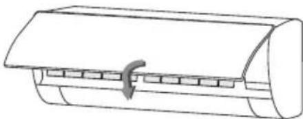
natural_image
Line drawing of a cylindrical air conditioner unit with a curved handle and internal slots (no text or symbols)natural_image
Technical line drawing of a mechanical assembly with mounting brackets and fasteners (no text or symbols)Отвор за стена
natural_image
Two hand-drawn diagrams showing a mechanical assembly or repair process, with no visible text or symbols.Електрическа схема
Външнототяло
natural_image
Technical line drawing of a front-end air duct fan with labeled dimensions H and L (no text or symbols beyond labels)
| Outdoor Dimensions (mm)LxHxD | Mounting Dimensions | |
| Distance A (mm) Distance | B (mm) | |
| 735x475x250 453 280 | ||
| 790x520x280 508 314 | ||
| 848x670x354 544 354 | ||
Леви крачета за
МОНТАЖ
Десни крачета
за монтаж

natural_image
Technical line drawing of a mechanical device with internal components and wiring (no text or symbols)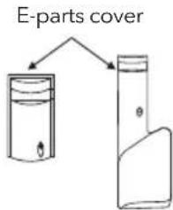
Електрическа схема

Customer's Phone No.:
Адрес на купувача
Customer's Address:
Продавач
Dealer's Name:
Dealer's Address and tel. No
Подпис на клиента
Customer's Signature:
Dealer's Signature & Stamp
natural_image
Line drawing of hands installing or adjusting a cylindrical object on a base (no text or symbols)natural_image
Simple line drawing of a cylindrical object with a handle, resembling a folded paper or container (no text or symbols)
natural_image
Diagram of a car air conditioner unit with cooling fins and airflow direction arrow (no text or labels)natural_image
Diagram of a car air conditioner unit with cooling fins and heat exchanger (no text or labels)
natural_image
Line drawing of a cylindrical air conditioner unit with a curved handle (no text or symbols)natural_image
Technical line drawing of a mechanical frame assembly with mounting brackets and mounting holes (no text or symbols)Διάτρηση τοίχου
natural_image
Two diagrams showing hand positioning of a mechanical component between two vertical surfaces, with an arrow indicating direction (no text or symbols present)GR
natural_image
Technical line drawing of a front-end air duct fan with labeled dimensions H and L (no text or symbols beyond labels)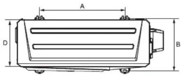
| Outdoor Dimensions (mm)LxHxD | Mounting Dimensions | |
| Distance A (mm) | Distance B (mm) | |
| 735x475x250 453 280 | ||
| 790x520x280 508 314 | ||
| 848x670x354 544 354 | ||
natural_image
Line drawing of two hands holding a cylindrical object (no text or symbols)Posebni oprez
natural_image
Line drawing of a cylindrical mechanical component with a handle and internal slots (no text or symbols)
natural_image
Diagram of a car air conditioner unit with cooling fins and airflow direction arrow (no text or labels)- Koristite obje ruke da biste otvorili panel bočno sa obe strane u pravcu koji pokazuje strelica.
- Oslobodite filter za zrak i uklonite ga.
natural_image
Diagram of a car air conditioner unit with airflow arrow indicating airflow direction (no text or symbols)
natural_image
Line drawing of a cylindrical air conditioner unit with a curved handle (no text or symbols)natural_image
Technical line drawing of a mechanical frame assembly with mounting brackets and mounting holes (no text or symbols)Zidni otvor
Put cjevovoda
- Ovisno o položaju jedinice, cjevovodi mogu biti postavljeni postrance sa lijeve ili desne strane (slika 1), ili okomito sa stražnje strane (slika 2) (zavisno od dužine cijevi unutrašnje jedinice). U slučaju bočnog postavljanja, odsjeći reznu ploču na suprotnoj strani.
slika 1
natural_image
Two diagrams showing hand positioning of a mechanical component with arrows indicating direction (no text or symbols)Dijagram el. instalacija
- Ako je vaš klima uređaj opremljen kablom za povezivanje, kablovi unutrašnje jedinice su tvornički povezani, nema potrebe za povezivanjem.
- Ako kabel za povezivanje nije osiguran, potrebno je povezivanje
Nakon instalacije, provjerite:
- da li su vijci dobro pričvršćeni, i nema opasnosti od otpuštanja.
- priključak ploče za prikazivanje bez obzira da li je postavljen na pravo mjesto i ne dodiruje ploču terminala.
- da li je poklopac kontrolne kutije dobro zatvoren
Konstantna brzina
Vanjska jedinica

Vanjska jedinica
Promjenjiva brzina
Vanjska jedinica
Vanjska jedinica
Konektor
Ako postoji konektor,
povežite direktno.
NAPOMENA:
Ovaj priručnik obično uključuje režim instalacija za različite vrste klima uređaja. Ne možemo isključiti mogućnost da neki posebni tipovi dijagrama instalacija nisu uključeni.
Dijagram je samo referenca. Ako se proizvod razlikuje od ove sheme instalacija, pogledajte detaljnu shemu električnih instalacija na uređaju koji ste kupili.
POSTAVLJANJE VANJSKE JEDINICE PLIN R32
natural_image
Technical line drawing of a large industrial fan or fan assembly with dimension labels H and L (no text or symbols on the diagram itself)
| Veličina vanjske jedinice (mm)LxHxD | Mounting Dimensions | |
| Distance A (mm) | Distance B (mm) | |
| 735x475x250 453 280 | ||
| 790x520x280 508 314 | ||
| 848x670x354 544 354 | ||
natural_image
Diagram of a mechanical linkage system with arrows indicating motion (no text or symbols)PROVJERANAKONINSTALACIJEIPROBNIRAD
natural_image
Line drawing of two hands holding a cylindrical object with a base, no text or symbols presentПособно внимание
natural_image
Simple line drawing of a cylindrical device with a handle and internal components (no text or symbols)
natural_image
Diagram of a car air duct with internal grid structure and downward arrow (no text or symbols)natural_image
Diagram of a car air conditioner unit with internal grid structure and airflow direction arrow (no text or symbols)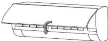
natural_image
Line drawing of a cylindrical air conditioner unit with a handle and ventilation slots (no text or symbols)natural_image
Technical line drawing of a mechanical bracket assembly (no text or symbols)Sиден отвор
natural_image
Two hand-drawn diagrams showing a mechanical assembly or repair process, with no visible text or symbols.Надворешна ед.
Надворешна ед.
Променлива брзина
Надворешна ед.
Надворешна ед.
natural_image
Technical line drawing of a rectangular fan with internal blades and height dimension labeled H and L (no text or symbols beyond labels)
| Outdoor Dimensions (mm)LxHxD | Mounting Dimensions | |
| Distance A (mm) | Distance B (mm) | |
| 735x475x250 453 280 | ||
| 790x520x280 508 314 | ||
| 848x670x354 544 354 | ||

Date of installation
natural_image
Simple line drawing of a cylindrical object with a handle and internal compartments (no text or symbols)
natural_image
Diagram of a car air duct system with internal grid structure and downward arrow (no text or symbols)natural_image
Diagram of a car air conditioner unit with airflow direction indicated by an arrow (no text or symbols)
natural_image
Line drawing of a cylindrical air conditioner unit with a clamped handle (no text or symbols)Verificare inainte de utilizare
natural_image
Technical line drawing of a mechanical assembly with mounting brackets and mounting holes (no text or symbols)Montare prin perete
natural_image
Two diagrams showing hand positioning of a mechanical component with a ruler, no text or symbols presentSchema de conexiuni
natural_image
Technical line drawing of a large industrial fan or fan assembly with dimension labels H and L (no text or symbols on the diagram itself)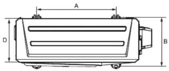
| Outdoor Dimensions (mm)LxHxD | Mounting Dimensions | |
| Distance A (mm) | Distance B (mm) | |
| 735x475x250 453 280 | ||
| 790x520x280 508 314 | ||
| 848x670x354 544 354 | ||
Picior instalare stanga
Picior instalare dreapta

Aer eliminat
Montati conducta de conectare
Conectati unitatea exterioara la teava de legatura:
Inclinati contra-gaura conductei de conectare la supapa de oprire si strangeti piulita conica cu degetele. Apoi strangeti piulita Taper cu o cheie de cuplu. La prelungirea tubulaturii, trebuie adaugata o cantitate suplimentara de agent frigorific, astfel incat functionarea si performanta aparatului de aer conditionat sa nu fie compromise.
natural_image
Technical diagram showing mechanical assembly with arrows indicating motion (no text or symbols)Conducta de lichid
Conducta de gaz
Cheie de piulite
Capacul supapei
INSTALARE UNITATE EXTERIOARA
Conexiune cabluri
natural_image
Technical line drawing of a mechanical device with internal components and wiring (no text or symbols)E-capacul pieselor

flowchart
graph TD
    A["Container 1"] --> B["Container 2"]
Schema de conexiuni
natural_image
Line drawing of two hands holding a cylindrical object (no text or symbols)Posebna previdnost
natural_image
Simple line drawing of a cylindrical object with a handle and internal compartments (no text or symbols)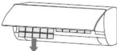
natural_image
Diagram of a car air conditioner unit with cooling fins and airflow direction arrow (no text or labels)natural_image
Diagram of a car air conditioner unit with internal grid structure and airflow direction arrow (no text or labels)
natural_image
Line drawing of a cylindrical air conditioner unit with a curved handle (no text or symbols)| Nazivni tokNaprave (A) | NazivniPresek ( mm^2 ) |
| >3 and ≤ 6 0.75 | |
| >6 and ≤10 1 | |
| >10 and ≤16 1.5 | |
| >10 and ≤16 2.5 | |
| >10 and ≤16 4 | |
| >10 and ≤16 6 |
natural_image
Technical line drawing of a mechanical support frame with mounting brackets and mounting holes (no text or symbols)Outlet material preparation
Slika 2

natural_image
Diagram of a hand holding a cylindrical object with a ruler inserted, showing an arrow indicating direction (no text or symbols present)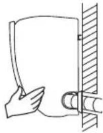
natural_image
Simple line drawing of a hand holding a document next to a vertical wall with a cylindrical object (no text or symbols)Vezalna shema
K zunanji enoti

K zunanji enoti
Spremenljiva hitrost
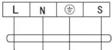
K zunanji enoti

K zunanji enoti
Konektor
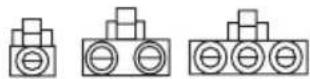
Če je na voljo konektor, priključite direktno.
OPOMBA:
natural_image
Technical line drawing of a rectangular fan with open lid and side panel, showing internal blades and mounting base (no text or symbols)
| Outdoor Dimensions (mm)LxHxD | Mounting Dimensions | |
| Distance A (mm) Distance B (mm) | ||
| 735x475x250 453 280 | ||
| 790x520x280 508 314 | ||
| 848x670x354 544 354 | ||
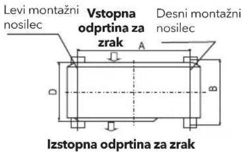
| Piping length | Amount of refrigerant to be added | Amount of refrigerant for the unit | |
| 5M Not needed | |||
| 5-15M | CC12000Btu 15g/m 1 kg | ||
| CC18000Btu 30g/m 2 kg | |||

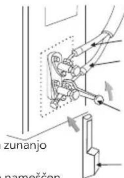
Cev za tekoče sredstvo Cev za uplinjeno sredstvo
Pritezni ključ
Pokrov zapornega ventil
natural_image
Line drawing of hands holding a cylindrical object (no text or symbols)Posebna opreznost
natural_image
Line drawing of a cylindrical air conditioner unit with a handle (no text or symbols)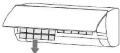
natural_image
Diagram of a car air conditioner unit with cooling fins and airflow direction arrow (no text or labels)- Koristite obe ruke da biste otvorili panel bočno sa obe strane u pravcu koji pokazuje strelica.
- Oslobodite filter za vazduh i uklonite ga.
Očistite filter za vazduh
Koristite usisivač ili vodu za ispiranje filtera, a ako je filter jako prljav (npr. masna prljavština), očistite ga toplom vodom (ispod 45 °C) sa blagim rastvorom deterdženta, a zatim stavite filter da se osuši na vazduhu.
Postavite filter
- Vratite osušeni filter obrnutim redosledom od uklanjanja, zatim zatvorite panel.

natural_image
Diagram of a car air conditioner unit with internal grid structure and airflow direction arrow (no text or symbols)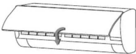
natural_image
Line drawing of a cylindrical air conditioner unit with a curved handle (no text or symbols)Proverite pre upotrebe
- Proverite da li su svi otvori za dovod i odvod vazduha blokirani.
- Proverite da li postoji začepljenje na izlazu za vodu odvodne cevi i odmah ga očistite ukoliko ga ima.
- Proverite da li je uzemljenje dobro postavljeno.
- Proverite da li su baterije daljinskog upravljača instalirane i da li je napajanje adekvatno.
- Proverite da li je došlo do oštećenja na nosaču za montažu spoljašnje jedinice, a ako ih ima, molimo kontaktirajte naš lokalni servisni centar.
Održavanje nakon upotrebe
- Isključite izvor napajanja klima uređaja, isključite glavni prekidač napajanja i izvadite baterije iz daljinskog upravljača.
- Očistite filter i telo jedinice.
- Uklonite prašinu i prljavštinu sa spoljašnje jedinice.
- Proverite da li je došlo do oštećenja u nosaču za montažu spoljašnje jedinice, i ako ih ima, molimo kontaktirajte naš lokalni servisni centar.

OPREZ!
Nemojte sami popravljati klima uređaj, jer pogrešno održavanje može prouzrokovati strujni udar ili požar ili eksploziju. Molimo vas da se obratite ovlašćenom servisnom centru i dopustite stručnim licima da sprovedu održavanje, a provera sledećih stavki pre kontaktiranja radi održavanja može uštedeti vaše vreme i novac.
OTKLANJANJE PROBLEMA
| Pojava Otklanjanje problema | |
| Klima uređaj ne radi. | Možda postoji prekid napajanja. → Sačekajte da se napajanje povratiMožda utikač za napajanje nije čvrsto postavljen u utičnici. → Proverite i čvrsto ga postavite.Osigurač za napajanje neispravan. → Zamenite osigurač.Još uvek nije vreme aktiviranja. → Sačekajte ili otkažite tajmer. |
| Klima uređaj ne radi odmah po gašenju. | Ako se klima uređaj uključi odmah nakon isključivanja zaštitni prekidač će odložiti rad na 3 do 5 minuta. |
| Klima uređaj prestaje da radi ubrzo pošto se uključi. | Možda je dostigao podešenu temepraturu, što je česta pojava.Možda je u stanju odmrzavanja. → Automatski će se pokrenuti posle procesa odmrzavanja.Možda je podešen tajmer za gašenje. → Podestite tajmer. |
| Izduvava vazduh ali ne greje/hladi. | Prekomerno nakupljanje prašine na filteru, blokira ulaz i izlaz vazduha, i izuzetno mali ugao lopatica će uticati na efekat hlađenja i zagrevanja. → Molimo očistite filter, uklonite prepreke na ulazu i izlazu vazduha i regulišite ugao lopatica.Slab učinak hlađenja i grejanja uzrokovan je Otvaranjem vrata i prozora. →Molimo vas zatvorite vrata, prozore, ventilacione otvore, itd.Funkcija pomoćnog grejanja nije uključena, što može dovesti do lošeg toplotnog efekta. → Uključite pomoćnu funkciju grejanja. (samo za modele sa funkcijom pomoćnog grejanja)Postavka režima nije ispravna, a postavke temperature i brzine izduvavanje nisu prikladne. → Molimo ponovo izaberite režim i podesite odgovarajuću temperaturu i brzinu izduvavanja. |
| Osećaju se neprijatni mirisi u unutrašnjoj jedinici. | Sam klima uređaj nema nepoželjan miris. Ako ima mirisa, to može biti zbog nakupljanja mirisa u okolini. → Očistite filter za vazduh ili aktivirajte funkciju čišćenja. |
| Javlja se zvuk vode koja teče tokom rada klima uređaja. | Kada se klima uređaj pokrene ili zaustavi, ili kada se kompresor pokrene ponekada se čuje zvuk kao da teče voda. → To je zvuk rashladnog sredstva, a ne kvar. |
| “Klik”zvuk se čuje tokom uključivanja i isključivanja. | Zbog promene temperature, panel i ostali delovi nabreknu što stvara ovaj zvuk.→ To je normalno, nije kvar. |
| Unutrašnja jedinica proizvodi čudne zvukove. | Zvuk ventilatora ili kompresora se uključuje ili isključuje.Kada se odmrzavanje pokrene ili prestane da radi, čuje se zvuk. → To je zbog toga što je rashladno sredstvo proticalo u obrnutom smeru. To nije kvar.Previše nakupljanje prašine u filteru za vazduh unutrašnje jedinice može dovesti do stvaranja zvuka. → Na vreme očistite filtere za vazduh.Previše buke kada je uključen “Strong wind”. → Ovo je normalno, ako se osećate nelagodno, molimo Vas da deaktivirate funkciju “Strong wind”. |
| Ima kapi vode svuda po površini unutrašnje jedinice. | Kada je vlažnost okoline visoka, kapi vode će se nakupiti oko izlaza vazduha ili panela, itd. → Ovo je uobičajena pojava.Produženo hlađenje u otvorenom prostoru proizvodi kapi vode. → Zatvorite vrata i prozore.Premali ugao otvaranja peraja može rezultirati kapima vode na ulazu za vazduh.→ Povećajte ugao lopatica. |
| Tokom hlađenja unutrašnja jedinica se ponekada zamagli. | Dešava se ponekad kada su temperatura i vlažnost visoki. → To je zato što se unutrašnji vazduh brzo hladi. Nakon što prođe neko vreme, unutrašnja temperatura i vlažnost će se smanjiti i magla će nestati. |

natural_image
Technical line drawing of a mechanical assembly with mounting brackets and fasteners (no text or symbols)Zidni otvor
- Napravite otvor električnim čekićem ili vodenom bušilicom na unapred određenom položaju na zidu za cevovode, koji će nagnuti prema van za 5°-10°.
- Da bi se cevovode i kablove koji prolaze kroz zid zaštitili od oštećenja, kao i od glodara koji se mogu naseliti u šupljem zidu, ugradiće se zaštitni prsten za cev i zapečatiti cementom.
Napomena: Obično zidni otvor je > 60mm > 80mm . Izbegavajte ranije postavljene električnu žicu i tvrdi zid prilikom izrade otvora.

Put cevovoda
- U zavisnosti od položaja jedinice, cevovodi mogu biti postavljeni postrance sa leve ili desne strane (slika 1), ili vertikalno od pozadi (slika 2) (zavisno od dužine cevi unutrašnje jedinice). U slučaju bočnog polaganja, odseći reznu ploču na suprotnoj strani.
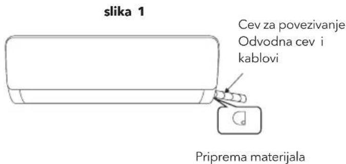
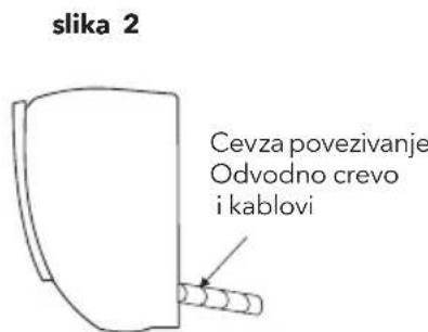
natural_image
Two hand-drawn diagrams showing a mechanical or electrical setup with no visible text, numbers, or symbols.Dijagram el. instalacija
- Ako je vaš klima uređaj opremljen kablom za povezivanje, kablovi unutrašnje jedinice su fabrički povezani, nema potrebe za povezivanjem.
- Ako kabl za povezivanje nije obezbeđen, potrebno je povezivanje.
Spoljašna jedinica

Spoljašna jedinica
Promenljiva brzina
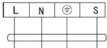
Spoljašna jedinica

Spoljašna jedinica
Konektor

Ako postoji konektor, povežite direktno.
NAPOMENA:
Ovaj priručnik obično uključuje režim instalacija za različite vrste klima uređaja. Ne možemo isključiti mogućnost da neki posebni tipovi dijagrama instalacija nisu uključeni.
natural_image
Technical line drawing of a front-end air duct fan with labeled dimensions H and L (no text or symbols beyond labels)
| Veličina spoljašnje jedinice (mm)LxHxD | Mounting Dimensions | |
| Distance A (mm) | Distance B (mm) | |
| 735x475x250 453 280 | ||
| 790x520x280 508 314 | ||
| 848x670x354 544 354 | ||
Leva instalaciona strana
Desna instalaciona strana
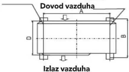
PROVERANAKON INSTALACIJE IPROBNIRAD
Provera posle instalacije
Provera električne sigurnosti
Velika Plana, TEHNOSERVIS, Nikole Pašića bb, 062/261622; 062/261628, dejan@tehnoservis.rs
Vranje, BETA COMPUTERS, Đure Jakšića 19, 017/400106; 064/8238337, betanabavka@gmail.com
Vršac, BEOSERVIS, Svetozara Miletića 84, 013/2824-136; 064/540-3280, nedic.s@sbb.rs
Vršac, ELEKTROSERVIS FLESH, Banatska 50, 063/302-741; 013/805-315, flesh@sbb.rs
Vučje, FRIGO SISTEM, JNA 38, 016/3427-382; 063/7 603 509, draganfrigosistem@yahoo.com
Zaječar, SERVIS VITA OBOD, Kursulina 20, 019/463-047; 063/485875, vitaobod@gmail.com
Žitorada, TPZR Majstor u Kuci, Toplički heroji 45, 027/8361068 065/8361068, prodaja.majstor@gmail.com
Zrenjanin, IMPERIUM KLIME, , 062/1066025; 061/6460663, imperiumklime@gmail.com
Zrenjanin, KLIMA CENTAR ZRENJANIN, Dr Kornela Radulovića 22, 023/511494; 060/511-4949, m.zdravko@gmail.com
Zrenjanin, SERVIS MIJATOVIĆ, Žarka Zrenjanina 43, 023/536-331; 063/583-561, duskomijatoviczr@gmail.com
Zrenjanin, ART COOL, Ivana Acina 35, 023/530-877; 063 7763259, artcool@sbb.rs

natural_image
Abstract spiral pattern with concentric white and purple concentric circles on a solid purple background (no text or symbols)


- UPUTSTVO ZA UPOTREBU
- SAFETY PRECAUTIONS
- WARNING!
- CAUTION!
- WEEE Warning
- NOTICES FOR USE
- The conditions of unit can't normally run
- Notes for heating
- Notes for turning off
- Emergency operation
- Airflow direction adjustment
- Specific caution
- NAMES OF EACH PART
- CLEAN AND CARE
- Clean the panel
- Clean the air filter
- Remove the air filter
- Mount the Filter
- Check before use
- Maintain after use
- TROUBLESHOOTING
- Immediately stop all operations and cut off the power supply, contact our Service center locally in following situations.
- NOTICES FOR INSTALLATION
- IMPORTANT NOTICES!
- Unpacking Inspection
- Safety Principles for Installing Air Conditioner
- Requirements For Installation Position
- Installation environment inspection
- Requirements of the mounting structure
- Electrical Safety Requirements
- Requirements for operations at raised height
- Grounding Requirements
- Others
- Packing list
- INSTALL INDOOR UNIT
- Mounting plate
- Wall-through Hole
- Route of Pipeline
- Drain pipe connection
- Wrap the Piping
- Fixing the Indoor Unit
- Wiring diagram
- NOTE:
- INSTALL OUTDOOR UNIT GAS R32
- Install the connection pipe
- INSTALL OUTDOOR UNIT
- Wiring Connection
- Vacuuming (Gas R32)
- Exclusive R32 refrigerant pump must be used in making R32 refrigerant vacuum.
- Outdoor condensation drainage (Heat pump type only)
- Installation:
- CHECK AFTER INSTALLATION AND TEST OPERATION
- Check after installation
- Electrical Safety Check
- Installation Safety Check
- Leak test of the refrigerant
- Test Operation
- Test Operation method:
- MAINTENANCE NOTICE
- Attention:
- Qualification requirements of maintenance personnel
- Inspection of the Site
- Operating Procedures
- Inspection of Cable
- Leakage check of R32 refrigerant
- Leak detection method:
- Removal and Vacuum Pumping
- Procedures of Charging Refrigerants
- Scrap and Recovery
- Scrap:
- Recovery:
- REMOTE CONTROLLER INSTRUCTIONS
- Attention
- Instructions of remote controller
- The icon meaning of remote controller
- Button function of remote controller
- ON/OFF:
- Temperature reduction -
- Temperature addition +
- Up and down swinging (External pendulum wind)
- Left and right swinging (Internal pendulum wind):
- FAN:
- Timer:
- TURBO:
- ECO:
- SLEEP:
- LIGHT
- LOCK
- Electricheating (Optional)
- CLEAN (Optional)
- IFEEL (Optional)
- Distribution function
- Combinatorial key: "Mode + ECO"
- Combinatorial key: "TIMER" + "SLEEP"(Optional)
- UPOZORENJE
- Upozorenje: Ovaj klima uređaj koristi R32 zapaljivo rashladno sredstvo.
- Posebna opreznost
- Očistite filter za vazduh
- Postavite filter
- Zidni otvor
- Put cjevovoda
- Dijagram el. instalacija
- NAPOMENA:
- PROVJERANAKONINSTALACIJEIPROBNIRAD
- AUTORIZOVANI SERVISI BiH
- Предпазни мерки
- Отвор за стена
- Електрическа схема
- Адрес на купувача
- Продавач
- Подпис на клиента
- Διάτρηση τοίχου
- Posebni oprez
- POSTAVLJANJE VANJSKE JEDINICE PLIN R32
- Пособно внимание
- Sиден отвор
- Date of installation
- Verificare inainte de utilizare
- Montare prin perete
- Schema de conexiuni
- Montati conducta de conectare
- INSTALARE UNITATE EXTERIOARA
- Conexiune cabluri
- Posebna previdnost
- Vezalna shema
- OPOMBA:
- Proverite pre upotrebe
- Održavanje nakon upotrebe
- OTKLANJANJE PROBLEMA
- Put cevovoda
- PROVERANAKON INSTALACIJE IPROBNIRAD
- Provera posle instalacije
- Provera električne sigurnosti
Brand : TESLA
Model : TC53P4-1832IA
Category : Air conditioner