
Belmar 50198 - Fan HONEYWELL - Free user manual and instructions
Find the device manual for free Belmar 50198 HONEYWELL in PDF.

| Product Type | Floor Fan |
| Model | Belmar 50198 |
| Brand | Honeywell |
| Dimensions (H x W x D) | Approx. 56 x 20 x 20 inches (142 x 51 x 51 cm) |
| Weight | Approx. 12 lbs (5.4 kg) |
| Power Supply | 120V AC, 60Hz |
| Power Consumption | 50 Watts |
| Number of Speed Settings | 3 |
| Oscillation | Yes, 90° |
| Remote Control | Included |
| Timer | 7-hour timer |
| Fan Head Tilt | Adjustable tilt (up/down) |
| Blade Diameter | 20 inches (50.8 cm) |
| Housing Material | Plastic and metal |
| Care and Cleaning | Wipe with damp cloth; do not immerse in water |
| Safety Features | Overheat protection, tip-over switch |
| Spare Parts | Replacement blades and grilles available from manufacturer |
| Repairability | Modular design allows replacement of major components |
Frequently Asked Questions - Belmar 50198 HONEYWELL
User questions about Belmar 50198 HONEYWELL
0 question about this device. Answer the ones you know or ask your own.
Ask a new question about this device
Download the instructions for your Fan in PDF format for free! Find your manual Belmar 50198 - HONEYWELL and take your electronic device back in hand. On this page are published all the documents necessary for the use of your device. Belmar 50198 by HONEYWELL.
USER MANUAL Belmar 50198 HONEYWELL
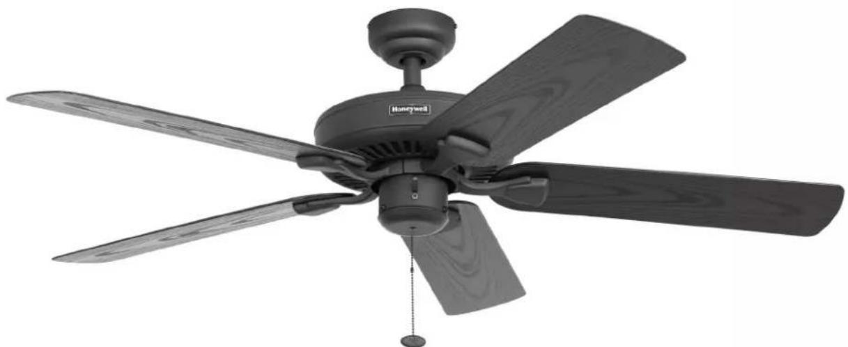
BELMAR 52" CEILING FAN
MODELS #50198, 50199
Español p. 19
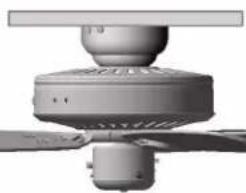
natural_image
Black and white photo of a multi-level air conditioner fan with wooden blades and a 'Honeywell' logo on the top (no text or symbols beyond branding)
LISTED
FOR WET
LOCATION

Questions, problems, missing parts? Before returning to your retailer, call our customer service department at 1-877-361-3883, Monday - Thursday, 8 am - 6 pm, EST and Friday, 8 am - 5 pm, EST.
WELCOME
TABLE OF CONTENTS
Care and Maintenance 2
Package Contents .... 3
Safety Information 4
Mounting Options 5
Mounting Bracket Installation 6
Standard or Angle Mounting Instructions .....7
Closemount Instructions....10
Wiring 11
Canopy Installation....12
Blade Installation 13
Final Installation ....14
Operating Installation....15
Replacement Parts List 16
Troubleshooting 17
Limited Lifetime Warranty....18
ATTACH YOUR RECEIPT HERE
Serial Number ____
Purchase Date ____
PREPARATION
Before beginning the assembly of this product, ensure that all parts are present. Compare all parts with the package contents list and hardware contents list. If any part is missing or damaged, do not attempt to assemble the product.
After opening the top of the carton, remove the mounting hardware package from the foam inserts, then remove the motor from the packaging and place it on a soft surface, such as a carpet, to avoid damage to the finish.
Estimated Assembly Time: Under 60 minutes
Tools Required for Assembly (not included): Electrical Tape, Phillips Screwdriver, Pliers, Safety Glasses, Step Ladder, and Wire Strippers
Helpful Tools (not included): AC Tester Light, Tape Measure, Wiring Handbook, and Wire Cutters
CARE AND MAINTENANCE
At least twice each year, lower the canopy to check the downrod assembly, and then tighten all screws on the fan. Clean the motor housing with only a soft brush or lint-free cloth to avoid scratching the finish. Clean the blades with a lint-free cloth. You may occasionally apply a light coat of furniture polish to wood blades for added protection.
Important: Shut off the main power supply before you begin any maintenance tasks. Do not use water or a damp cloth to clean the ceiling fan.
FAN WEIGHT
The net weight of this fan is: 14.52 lbs. (6,59 kg).
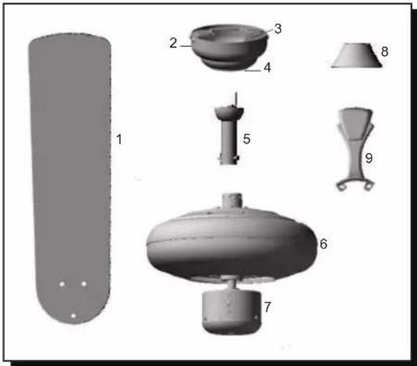
PACKAGE CONTENTS
Unpack your fan and check the contents. You should have the following items:
- Blade (5)
- Canopy
- Mounting Bracket
- Canopy Cover
- Downrod
- Motor Housing
- Switch Housing
- Yoke Cover
- Blade Arm (5)
- Loose parts bags containing (not shown): Mounting hardware, blade attachment hardware, electrical hardware, pull chains, wire connectors, etc.
SAFETY INFORMATION
Please read and understand this entire manual before attempting to assemble, operate, or install the product.
- Before you begin installing the fan, disconnect the power by removing fuses or turning off the circuit breakers.
- Make sure that all electrical connections comply with local codes, ordinances, the National Electrical Code, and ANSI/NFPA 70-199. Hire a qualified electrician or consult a do-it-yourself wiring handbook if you are unfamiliar with installing electrical wiring.
- Make sure the installation site you choose allows a minimum clearance of 7 ft. (2,14 m) from the blades to the floor and at least 30 in. (76 cm) from the end of the blades to any obstruction.

DANGER

When using an existing outlet box, make sure the outlet box is securely attached to the building structure and can support the full weight of the fan. Failure to do this can result in serious injury or death. The stability of the outlet box is essential in minimizing wobble and noise in the fan after installation is complete.

DANGER

If using the fan in a damp location, the fan must be connected to a supply circuit that is protected by a Ground Fault Circuit Interrupter (GFCI) to reduce the risk of personal injury, electrical shock or death.

WARNING

To reduce the risk of fire or electric shock, do not use the fan with any solid-state speed-control device or control the fan speed with a full-range dimmer switch.

WARNING

To reduce the risk of fire, electric shock, or personal injury, do not bend the blade arms when installing them, balancing the blades, or cleaning the fan. Do not insert objects between the rotating fan blades.

WARNING

To reduce the risk of fire, electric shock, or personal injury, mount the fan to an outlet box marked "ACCEPTABLE FOR FAN SUPPORT" and use the mounting screws provided with the outlet box. Most outlet boxes commonly used for the support of lighting fixtures are not acceptable for fan support and may need to be replaced. Consult a qualified electrician if in doubt. Secure the outlet box directly to the building structure. The outlet box and its support must be able to support the moving weight of the fan, at least 35 lbs. (15,88 kg).

CAUTION

Read all instructions and safety information before installing your new fan. Review the accompanying assembly diagrams.

CAUTION

Carefully check all screws, bolts, and nuts on the motor housing to ensure that they are secured.
MOUNTING OPTIONS

DANGER

Turn off the circuit breakers and the wall switch to the fan supply line leads. Failure to disconnect the power supply prior to installation may result in serious injury or death.
-
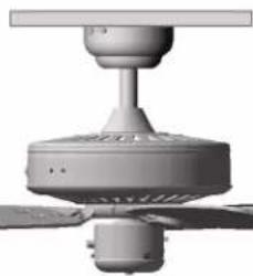
Your fan has 3 mounting options:
-
Standard (Fig. 1)
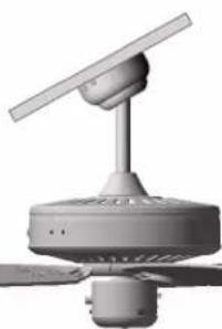
- Angled (Fig. 2)
- Closemount (Fig. 3)
Note: The fans in figures 1 through 3 are not the actual fan in your package, they are representation of the 3 different mounting options.
Important: If using the angle mount, check to ensure the ceiling angle is not steeper than 16^ .
Helpful Hint: Downrod style mounting is best suited for ceilings 8 ft. or higher. For taller ceilings you may want to use a longer downrod (sold separately). Angle style mounting is best suited for angled or vaulted ceilings. A longer downrod is sometimes necessary to ensure proper blade clearance. Closemount-style mounting is more suitable for ceilings lower than 8 ft. (2,44 m) high.
- Ensure that the blades of the fan are 30 in. (76 cm) from any obstruction.
- Check the downrod length to ensure the blades will be at least 7 ft. (2,14 m) above your floor.
Fig. 1
natural_image
3D rendering of a white ceiling fan with three blades and central hub (no text or symbols visible)Fig. 2
natural_image
3D rendering of a modern office air conditioner unit with fan and propeller (no text or symbols visible)Fig. 3
natural_image
3D rendering of a ceiling fan with visible blades and central hub (no text or symbols)MOUNTING BRACKET INSTALLATION
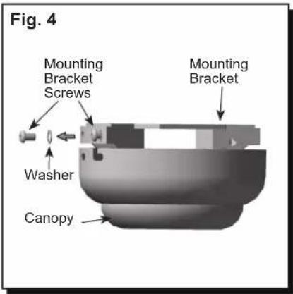
- Loosen all mounting bracket screws. Remove the two mounting bracket screws and washers from the round holes of canopy. Set aside for later use. Detach mounting bracket from canopy (Fig. 4).

Mounting Bracket
Screw

Washer
- Secure the mounting bracket to the outlet box using screws and washers provided with the outlet box (not included) (Fig. 5).
Note: It is very important to use proper hardware when installing the mounting bracket as it supports the fan.
Important: If using the angle mount, ensure the open end of the mounting bracket is installed facing the peak of the ceiling.
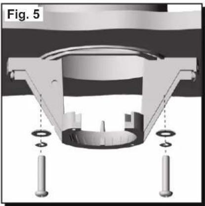
natural_image
Mechanical assembly diagram showing a central component with multiple supports and mounting holes, labeled Fig. 5 (no text or symbols on the diagram itself)STANDARD OR ANGLE MOUNTING INSTRUCTIONS
-
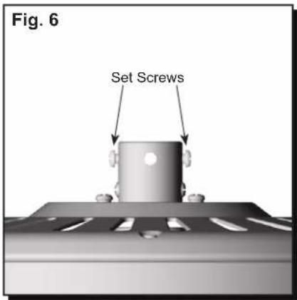
Partially loosen the two set screws in the yoke at the top of the motor housing (Fig. 6).
-
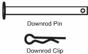
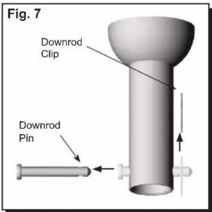
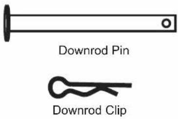
Remove the downrod pin and downrod clip from the downrod (Fig. 7).
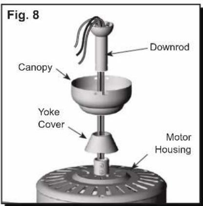
- Thread the wires from the motor housing through the yoke cover, canopy, and out the top of the downrod (Fig. 8).
STANDARD OR ANGLE MOUNTING INSTRUCTIONS
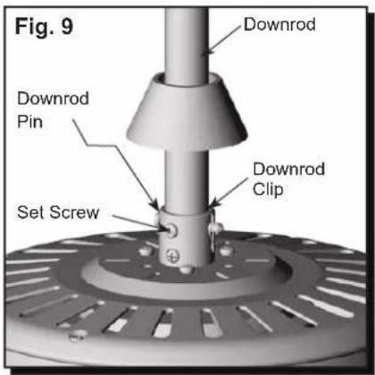
- Slide the downrod into the yoke of the motor housing, align the holes, and re-install the downrod pin and downrod clip. Then re-tighten the two set screws (Fig. 9).
-
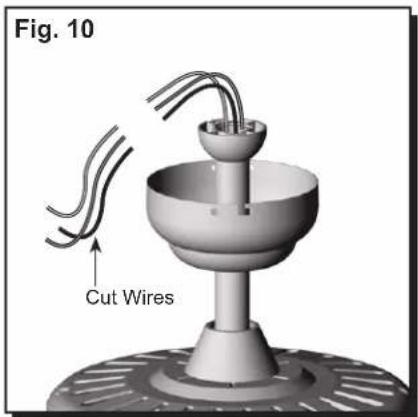
Depending on the length of downrod you use, you may need to cut the lead wires back to simplify the wiring. If you decide to cut back the lead wires, it is suggested that you do so in the following manner: Take the lead wires and make sure that you have pulled them all the way through the top of the downrod and measure 8 in. (2,44 m) of lead wire, and then cut the excess wire off with wire cutters (not included) (Fig. 10).
-
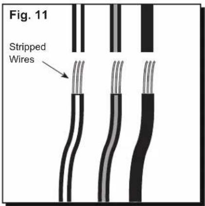
If you cut back the lead wire in Step 10, strip 1/2 in. of insulation from the end of each wire. Twist the stripped ends of each strand of wire within the insulation with pliers (not included) (Fig. 11).
Note: If you did not cut back the lead wires in Step 10, Step 11 is not necessary and you may proceed to Step 12 instead.
STANDARD OR ANGLE MOUNTING INSTRUCTIONS
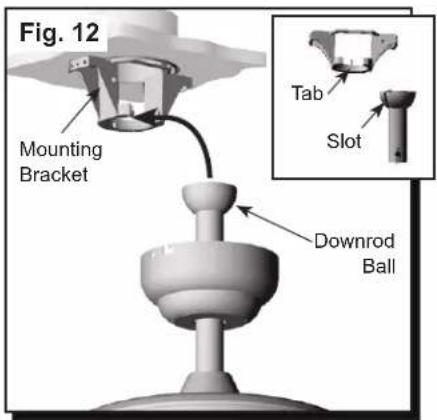
- Install the downrod ball into the mounting bracket opening. Align the slot in the ball with the tab in the mounting bracket. The downrod should not rotate if installed correctly (Fig. 12).
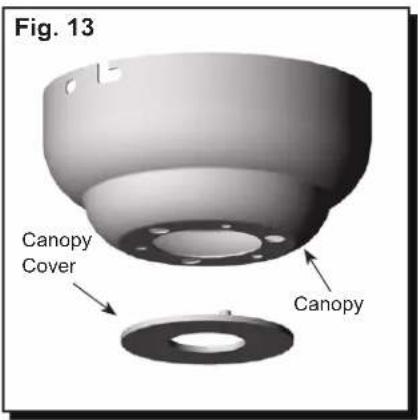
CLOSEMOUNT INSTRUCTIONS
- Remove the canopy cover from the bottom of the canopy (Fig. 13)
Helpful Hint: The downrod, hanging ball, and canopy cover are not used in this type of installation.
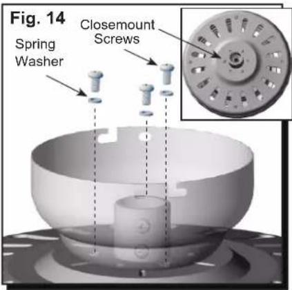
- Remove the three closemount screws and washers from the top of the motor housing. Align the canopy with the closemount screw holes in the top of the motor housing. Secure the canopy to the top of the motor housing by reinstalling the closemount screws and washers into the top of the motor housing (Fig. 14).

Closemount Screw

Spring Washer
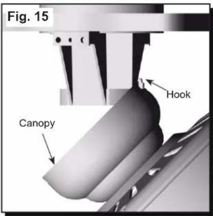
- Raise the fan and place the canopy on the mounting bracket hook for wiring (Fig. 15).
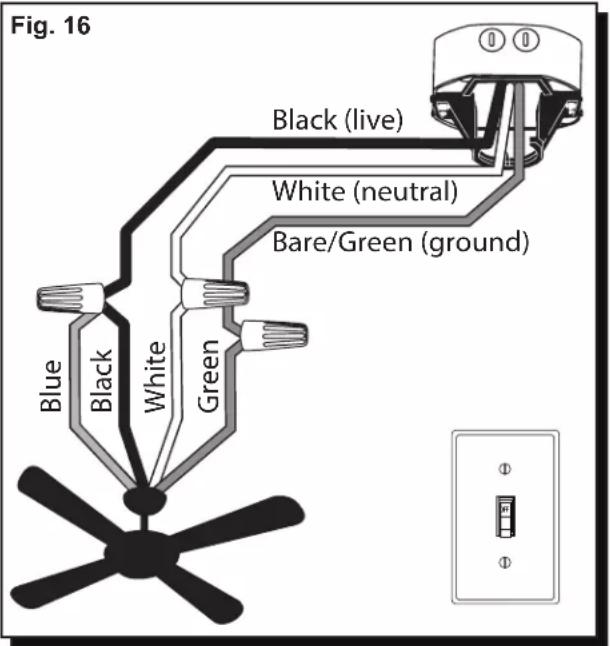
WIRING

CAUTION

Be sure outlet box is properly grounded or that a ground (green or bare) wire is present.

WARNING

If house wires are different colors than referred to in the following step, stop immediately. A professional electrician is recommended to determine wiring. Incorrect wire connection can damage the receiver and could cause fire or injury.
-
Connect supply and fan wires according to the diagram (Fig. 16) and these steps:
-
Connect the Green wires from the fan and mounting bracket to the Bare/Green (ground) supply wire.
- Connect the Black and Blue wire from the fan to the Black (live) supply wire.
- Connect the White wire from the fan to the White (neutral) supply wire.
Secure all wiring connections together with wire connectors and push all connected wires back into the outlet box.
Important: The black fan wire is power for fan. The blue fan wire is power for a light kit, sold separately. The white wire from the fan is common/neutral. The green wires from the fan and mounting bracket are ground wires.
Wire Connector
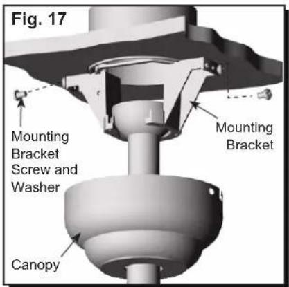
CANOPY INSTALLATION
- Lift the canopy up so the partially installed mounting bracket screws are situated in the L-slots on each side of the canopy. Rotate the canopy clockwise and install the remaining mounting bracket screws and washers from Step 4 (Fig. 17).

Mounting Bracket Screw

Washer
BLADE INSTALLATION
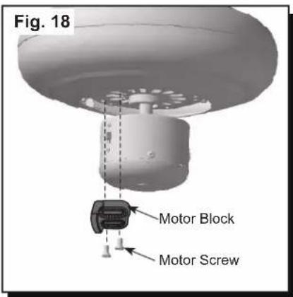
- Remove the ten motor screws from underside of motor and save for blade arm attachment. Discard the plastic motor blocks but keep the screws (Fig. 18).
Motor Screw
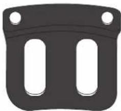
natural_image
Simple black plastic component with two side slots and two top holes (no text or symbols)Motor Block
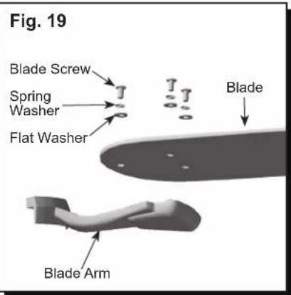
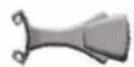
- Partially insert three blade screws along with spring washers and flat washers to attach the blade arm to the blade. Then, tighten each blade screw starting with the one in the middle. Repeat with remaining blades (Fig. 19).

Blade Screw Spring Washer Flat Washer

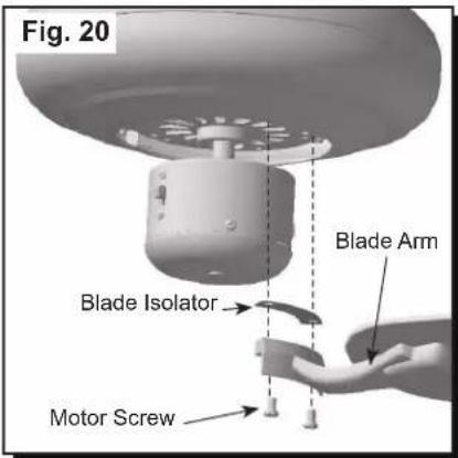
- Insert two previously removed motor screws through one blade arm and blade isolator and then into the motor. Tighten motor screws securely. Repeat with remaining blade arms, making sure to completely secure each blade arm before proceeding with to the next (Fig. 20).
Motor Screw
FINAL INSTALLATION
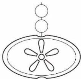
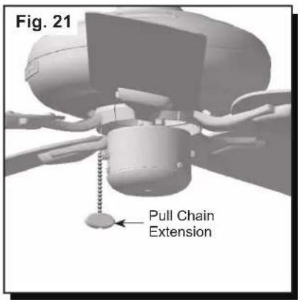
- Attach the pull chain extension to the fan pull chain (Fig. 21).
natural_image
Simple line drawing of a fan or impeller with a central hub and two circular tops (no text or symbols)Pull Chain Extension
OPERATING INSTRUCTIONS
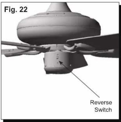
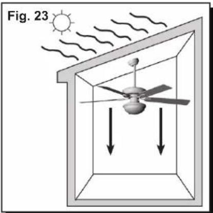
- Use the fan reverse switch, located on the side of the switch housing, to optimize your fan for seasonal performance (Fig. 22).
Using a ceiling fan will allow you to raise your thermostat in the summer and lower your thermostat in the winter without sacrificing comfort.
Important: The reverse switch must be set either completely up or down in order for the fan to function correctly. If the reverse switch is set in the middle position, the fan will not operate.
Important: Wait for the fan to stop before moving the reverse switch.
- In warmer weather, push the reverse switch down, which will result in downward airflow creating a wind chill effect (Fig. 23).
Note: Energy savings are possible by turning on the ceiling fan and setting the thermostat a few degrees warmer. To maximize savings, turn ceiling fan off when no one is in the room.
- In cooler weather, push the reverse switch up and the fan to low, which will result in upward airflow that can help move stagnant, hot air off the ceiling area. By mixing the air, the heat may not have to run as often and may yield energy savings (Fig. 24).
natural_image
Diagram of a ceiling fan inside a structure with sunlight and wind lines, no text or symbols present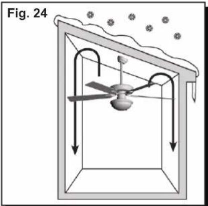
natural_image
Diagram of a ceiling structure with a central fan and airflow arrows, labeled Fig. 24 (no text or symbols on the diagram itself)REPLACEMENT PARTS LIST
For replacement parts, call the customer service department at 1-877-361-3883, 8 a.m. - 6 p.m., EST, Monday - Thursday, 8 a.m. - 5 p.m., EST, Friday.
| PIECE DESCRIPTION | MODEL 50198PART # | MODEL 50199PART # | |
| A Blade Arm 50198-A 50199-A | |||
| B Blade 50198-B 50199-B | |||
| C | Loose parts bags containing (not shown): Mounting hardware, blade attachment hardware, electrical hardware, pull chains, wire connectors, etc. | 50198-C 50199-C | |


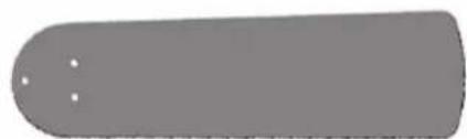
natural_image
Simple gray rounded rectangle shape with two small white dots on the top side (no text or symbols)TROUBLESHOOTING
At least twice each year, lower the canopy to check the downrod assembly, and then tighten all screws on the fan. Clean the motor housing with only a soft brush or lint-free cloth to avoid scratching the finish. Clean the blades with a lint-free cloth. You may occasionally apply a light coat of furniture polish to wood blades for added protection.
Important: Shut off the main power supply before you begin any maintenance tasks. Do not use water or a damp cloth to clean the ceiling fan.
Problem: The fan does not move
- Turn the power on or check the fuse.
- Turn the power off. Loosen the canopy and check all connections.
- Check that the connectors from the light kit fitter and fan are connected properly.
- Disable the power supply to the fan motor and re-start the motor.
- The blade is overweight. Do not install the unapproved blades.
Problem: The fan is noisy.
- Check and tighten all screws that hold the fan blades to the blade arms and the motor.
- Replace the cracked blade.
Problem: There is excessive wobbling
- Check and tighten all screws that hold the fan blades to the blade arms and the blade arms to the motor.
- Switch one blade with a blade from the opposite side. Or balance the fan using a balancing kit.
- Turn off the power. Loosen the canopy and verify that the mounting bracket is secure to the electrical outlet box.
- The bracket must be flush without movement against the outlet box.
LIMITED LIFETIME WARRANTY
Subject to the limitations set forth below, Hong Kong China Electric appliance Company (HKC) warrants the fan motor for this ceiling fan to be free from defects in workmanship and material for the life of the product. Also, subject to the limitations below, HKC warrants all ceiling fan parts (“ceiling fan parts” excludes the motor and parts made in whole or in part with glass) to be free from defects in workmanship and material for a period of one year after the date of purchase by the original purchaser at retail.
All claims must be made by the original purchaser, whether such purchaser purchased the product through a store or contractor. Ceiling fan part defects must be reported within the first year from the date of purchase. Parts made in whole or in part with glass and the finishes of metal and other surfaces are not warranted.
Purchasers are responsible for all costs of removing and reinstalling the product. Any damage to any part caused by ordinary wear and tear, accident, misuse, or improper installation, is not covered by this warranty. HKC assumes no responsibility whatsoever for fan installation. Any service performed by a non-licensed electrician will render the warranty invalid.
HKC's sole responsibility shall be to repair or replace the motor, parts, or product within the terms stated above. HKC SHALL NOT BE LIABLE FOR ANY LOSS OR DAMAGE OF ANY KIND, INCLUDING ANY INCIDENTAL OR CONSEQUENTIAL DAMAGES RESULTING DIRECTLY OR INDIRECTLY, FROM ANY BREACH OF WARRANTY, EXPRESS OR IMPLIED, OR ANY OTHER FAILURE OF THIS PRODUCT. SOME STATES DO NOT ALLOW THE EXCLUSION OR LIMITATION OF INCIDENTAL OR CONSEQUENTIAL DAMAGES SO THIS LIMITATION MAY NOT APPLY TO YOU.
IF THE ORIGINAL PURCHASER CEASES TO OWN THE FAN, THIS WARRANTY IS VOIDED.
Should the purchaser encounter a problem with your fan related to defects in workmanship or materials within the warranty period associated with the defective part, HKC agrees to replace the defective part without charge, or at its option, to replace the ceiling fan with a comparable or superior model.
HKC'S WARRANTIES ARE LIMITED TO THE WRITTEN WARRANTIES SET OUT IN THIS HKC CEILING FAN LIMITED LIFETIME WARRANTY. ALL OTHER EXPRESS AND IMPLIED WARRANTIES, INCLUDING, WITHOUT LIMITATION, THE IMPLIED WARRANTY OF FITNESS FOR A PARTICULAR PURPOSE AND THE IMPLIED WARRANTY OF MERCHANTABILITY ARE DISCLAIMED. SOME STATES DO NOT ALLOW THE DISCLAIMER OF IMPLIED WARRANTIES, SO THIS DISCLAIMER MAY NOT APPLY TO YOU.
To obtain warranty service, please write down your model number and call Customer Service at 1-877-361-3883, Monday - Thursday, 8 am - 6 pm, EST and Friday, 8 am - 5 pm, EST. Please have a copy of the receipt as proof of purchase.
The Honeywell Trademark is used under license from Honeywell International Inc. Honeywell International Inc. makes no representations or warranties with respect to this product. This product is manufactured for:
Hong Kong China Electric Appliance Manufacture Co., Ltd.
3059 Forest Hill Irene Rd, Suite 103
Germantown, TN 38138
1-877-361-3883
- BELMAR 52" CEILING FAN
- WELCOME
- TABLE OF CONTENTS
- ATTACH YOUR RECEIPT HERE
- PREPARATION
- CARE AND MAINTENANCE
- FAN WEIGHT
- PACKAGE CONTENTS
- SAFETY INFORMATION
- DANGER
- WARNING
- CAUTION
- MOUNTING OPTIONS
- MOUNTING BRACKET INSTALLATION
- STANDARD OR ANGLE MOUNTING INSTRUCTIONS
- CLOSEMOUNT INSTRUCTIONS
- WIRING
- CANOPY INSTALLATION
- BLADE INSTALLATION
- FINAL INSTALLATION
- OPERATING INSTRUCTIONS
- REPLACEMENT PARTS LIST
- TROUBLESHOOTING
- Problem: The fan does not move
- Problem: The fan is noisy.
- Problem: There is excessive wobbling
- LIMITED LIFETIME WARRANTY
Brand : HONEYWELL
Model : Belmar 50198
Category : Fan