Enteroc N1823 - Server Rocstor - Free user manual and instructions
Find the device manual for free Enteroc N1823 Rocstor in PDF.

| Product Type | Rackmount Server (2U) |
| Dimensions (H x W x D) | 3.5 x 17.2 x 25.6 in (88 x 437 x 650 mm) |
| Weight | 35 lb (15.9 kg) without drives |
| Power Supply | Dual redundant 800W (80 PLUS Platinum) |
| Processor | Intel Xeon Scalable (2nd Gen) up to 28 cores |
| Memory | Up to 1TB DDR4 ECC RDIMM (16 slots) |
| Storage Bays | 12x 3.5" hot-swap SATA/SAS (up to 16TB each) |
| Network Connectivity | 2x 10GbE RJ45, 2x 1GbE RJ45 |
| Remote Management | IPMI 2.0 with dedicated management port |
| Expansion Slots | 3x PCIe 3.0 x16, 2x PCIe 3.0 x8 |
| Cooling | 4x hot-swap 80mm fans (redundant) |
| Operating Temperature | 50°F to 95°F (10°C to 35°C) |
| Supported Operating Systems | Windows Server, Linux (CentOS, Ubuntu), VMware ESXi |
| Certifications | FCC, CE, UL, RoHS |
| Maintenance & Cleaning | Vacuum air filters monthly; clean with compressed air quarterly |
| Safety Precautions | Use ESD strap; ensure proper grounding; avoid blocking vents |
| Spare Parts & Repairability | Hot-swap PSUs, fans, and drives; replaceable CMOS battery |
Frequently Asked Questions - Enteroc N1823 Rocstor
User questions about Enteroc N1823 Rocstor
0 question about this device. Answer the ones you know or ask your own.
Ask a new question about this device
Download the instructions for your Server in PDF format for free! Find your manual Enteroc N1823 - Rocstor and take your electronic device back in hand. On this page are published all the documents necessary for the use of your device. Enteroc N1823 by Rocstor.
USER MANUAL Enteroc N1823 Rocstor
natural_image
Front view of a black rack-mounted server unit with orange ventilation grilles and a digital display (no visible text or symbols)Hardware Manual
Version 1.0
Table of Contents
Preface 3
Before You Begin....4
Chapter 1 Introduction .... 5
1.1 Key Features....5
1.2 Technical Specifications....6
1.3 RAID Concepts 7
1.4 Array Definition....10
1.4.1 Drive Group....10
1.4.2 Virtual Drive....11
Chapter 2 Getting Started....11
2.1 Packaging, Shipment and Delivery....11
2.2 Unpacking the NAS System....11
2.3 Identifying Parts of the NAS System....12
2.3.1 Front View....12
2.3.1.1 LCD Front Panel 13
2.3.2 Rear View....15
2.4 Drive Carrier Module 17
2.4.1 Disk Drive Status Indicators....17
2.5 Installing Hard Drives....18
2.5.1 Installing 3.5" Disk in a Disk Tray....18
2.5.2 Installing 2.5" Disk in a Disk Tray....20
2.6 Preparing the System....22
2.7 Powering On....23
Preface
About this manual
T
his manual provides information regarding the hardware features, installation and configuration of the SAS NAS System. Information contained in the manual has been reviewed for accuracy, but not for product warranty because of the various environment/OS/settings. Information and specifications will be changed without further notice. Some pictures and screenshots might be different with the actual machine.
This manual uses section numbering for every topic being discussed for easy and convenient way of finding information in accordance with the user's needs. The following icons are being used for some details and information to be considered in going through with this manual:

NOTES:
These are notes that contain useful information and tips that the user must give attention to in going through with the subsystem operation.

IMPORTANT!
These are the important information that the user must remember.

WARNING!
These are the warnings that the user must follow to avoid unnecessary errors and bodily injury during hardware and software operation of the subsystem.

CAUTION:
These are the cautions that user must be aware of to prevent damage to the equipment and its components.
Copyright
No part of this publication may be reproduced, stored in a retrieval system, or transmitted in any form or by any means, electronic, mechanical, photocopying, recording or otherwise, without the prior written consent.
Trademarks
All products and trade names used in this document are trademarks or registered trademarks of their respective owners.
Changes
The material in this document is for information only and is subject to change without notice.
Before You Begin
B
efore going through with this manual, you should read and focus on the following safety guidelines. Information about the NAS System's packaging and delivery are also included. To provide reasonable protection against any harm on the part of the user and to obtain maximum performance, user is advised to be aware of the following safety guidelines particularly in handling hardware components:
Upon receiving of the product:
◆ Place the product in its proper location.
To avoid unnecessary dropping out, make sure that somebody is around for immediate assistance.
It should be handled with care to avoid dropping that may cause damage to the product. Always use the correct lifting procedures.
Upon installing of the product:
✿ Ambient temperature is very important for the installation site. It must not exceed 30^ C. Due to seasonal climate changes; regulate the installation site temperature making it not to exceed the allowed ambient temperature.
Before plugging-in any power cords, cables and connectors, make sure that the power switches are turned off. Disconnect first any power connection if the power supply module is being removed from the enclosure.
◆ Outlets must be accessible to the equipment.
All external connections should be made using shielded cables and as much as possible should not be performed by bare hand. Using anti-static hand gloves is recommended.
In installing each component, secure all the mounting screws and locks. Make sure that all screws are fully tightened. Follow correctly all the listed procedures in this manual for reliable performance.
Controller Configuration
This NAS System supports single RAID controller configuration.
Packaging, Shipment and Delivery
Before removing the subsystem from the shipping carton, you should visually inspect the physical condition of the shipping carton.
✿ Unpack and verify that the contents of the shipping carton are complete and in good condition.
- Exterior damage to the shipping carton may indicate that the contents of the carton are damaged.
If any damage is found, do not remove the components; contact the dealer where you purchased the subsystem for further instructions.
Chapter 1 Introduction
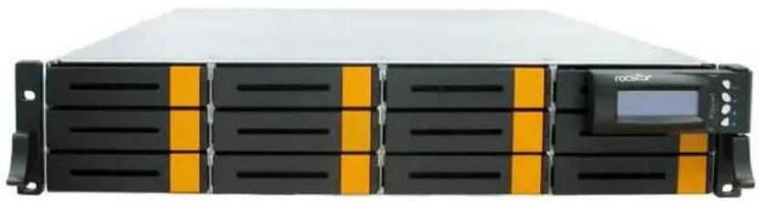
natural_image
Front view of a rack-mounted server unit with black and orange ventilation grilles and a digital display (no visible text or symbols)The NAS System
1.1 Key Features
- Configurable to 19" rack-mountable 2U chassis
- Supports up to Twelve (12) 2.5" and 3.5" hot-swappable 12Gb/s SAS/SATA hard drives
- Supports RAID levels 0, 1, 5, 6, 10, 50, 60
- Support Two 10Gb Ethernet ports for Server file-sharing application
- Supports hot spare and automatic hot rebuild
- Centralization of Data and Storage Management
- Real-time drive activity and status indicators
- Locally audible event notification alarm
- Allows online capacity expansion within the enclosure
1.2 Technical Specifications
| Hardware Platform |
| Intel Quad Core Xeon 3.3G processor |
| System Memory: 8GB DDR4 ECC SDRAM up to 64GB |
| Two 10Gb Ethernet ports (RJ-45) |
| Up to Twelve (12) 2.5" and 3.5" hot-swappable 12Gb/s SAS. 6Gb/s SATA hard drives |
| Real time drive activity and status indicators |
| Connect up to 128 3Gb/s, 6Gb/s, or 12Gb/s SATA and SAS devices |
| Two(2) 460W 80plus hot-swap power supplies with PFC |
| Expansion PCIE/PCI slot for H/W upgrade |
| RAID Controller |
| 1.2GHz dual core RAID on Chip (ROC) storage processor |
| RAID level RAID 0, 1, 5, 6, 10, 50, 60 |
| Support 1GB DDRIII cache memory |
| Support drive hot spare and automatic hot rebuild |
| Allow online capacity expansion within the enclosure |
| Locally audible event notification alarm |
| Environmental |
| Relative humidity : 10%~85% Non-condensing |
| Operating temp : 10°C~40°C(50°F~104°F) |
| Power requirements |
| AC 100V ~ 240V Full range |
| 10A ~ 5A, 47~63Hz |
| Physical Dimension |
| 88(H) x 482(W) x 620(D) mm |
Specifications are subject to change without notice.
1.3 RAID Concepts
RAID Fundamentals
The basic idea of RAID (Redundant Array of Independent Disks) is to combine multiple inexpensive disk drives into an array of disk drives to obtain performance, capacity and reliability that exceeds that of a single large drive. The array of drives appears to the host computer as a single logical drive.
Five types of array architectures, RAID 1 through RAID 5, were originally defined; each provides disk fault-tolerance with different compromises in features and performance. In addition to these five redundant array architectures, it has become popular to refer to a non-redundant array of disk drives as a RAID 0 arrays.
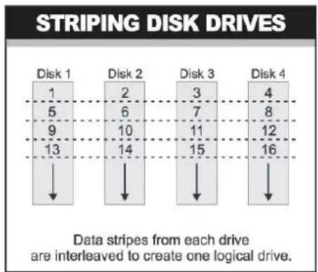
Disk Striping
Fundamental to RAID technology is striping. This is a method of combining multiple drives into one logical storage unit. Striping partitions the storage space of each drive into stripes, which can be as small as one sector (512 bytes) or as large as several megabytes. These stripes are then interleaved in a rotating sequence, so that the combined space is composed alternately of stripes from each drive. The specific type of operating environment determines whether large or small stripes should be used.
Most operating systems today support concurrent disk I/O operations across multiple drives. However, in order to maximize throughput for the disk subsystem, the I/O load must be balanced across all the drives so that each drive can be kept busy as much as possible. In a multiple drive system without striping, the disk I/O load is never perfectly balanced. Some drives will contain data files that are frequently accessed and some drives will rarely be accessed.
bar
STRIPING DISK DRIVES | Disk | 1 | 5 | 9 | 13 | |---|---|---|---|---| | Disk 1 | 1 | 5 | 9 | 13 | | Disk 2 | 2 | 6 | 10 | 14 | | Disk 3 | 3 | 7 | 11 | 15 | | Disk 4 | 4 | 8 | 12 | 16 | Data stripes from each drive are interleaved to create one logical drive.By striping the drives in the array with stripes large enough so that each record falls entirely within one stripe, most records can be evenly distributed across all drives. This keeps all drives in the array busy during heavy load situations. This situation allows all
drives to work concurrently on different I/O operations, and thus maximize the number of simultaneous I/O operations that can be performed by the array.
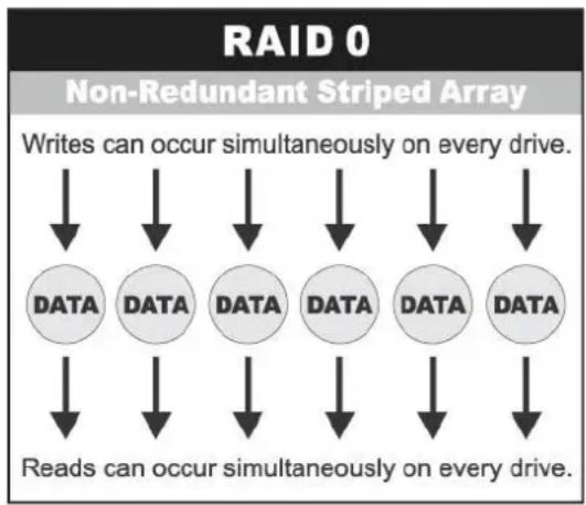
Definition of RAID Levels
RAID 0 is typically defined as a group of striped disk drives without parity or data redundancy. RAID 0 arrays can be configured with large stripes for multi-user environments or small stripes for single-user systems that access long sequential records. RAID 0 arrays deliver the best data storage efficiency and performance of any array type. The disadvantage is that if one drive in a RAID 0 array fails, the entire array fails.
flowchart
graph TD
    A["Reads can occur simultaneously on every drive."] --> B["DATA"]
    A --> C["DATA"]
    A --> D["DATA"]
    A --> E["DATA"]
    A --> F["DATA"]
    A --> G["DATA"]
    H["Writes can occur simultaneously on every drive."] --> I["Data"]
    H --> J["Data"]
    H --> K["Data"]
    H --> L["Data"]
    H --> M["Data"]
    H --> N["Data"]
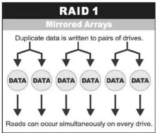
RAID 1, also known as disk mirroring, is simply a pair of disk drives that store duplicate data but appear to the computer as a single drive. Although striping is not used within a single mirrored drive pair, multiple RAID 1 arrays can be striped together to create a single large array consisting of pairs of mirrored drives. All writes must go to both drives of a mirrored pair so that the information on the drives is kept identical. However, each individual drive can perform simultaneous, independent read operations. Mirroring thus doubles the read performance of a single non-mirrored drive and while the write performance is unchanged. RAID 1 delivers the best performance of any redundant array type. In addition, there is less performance degradation during drive failure than in RAID 5 arrays.
flowchart
graph TD
    A["RAID 1"] --> B["Mirrored Arrays"]
    B --> C["Duplicate data is written to pairs of drives."]
    C --> D["DATA"]
    C --> E["DATA"]
    C --> F["DATA"]
    C --> G["DATA"]
    C --> H["DATA"]
    D --> I["Reads can occur simultaneously on every drive."]
    E --> I
    F --> I
    G --> I
    H --> I
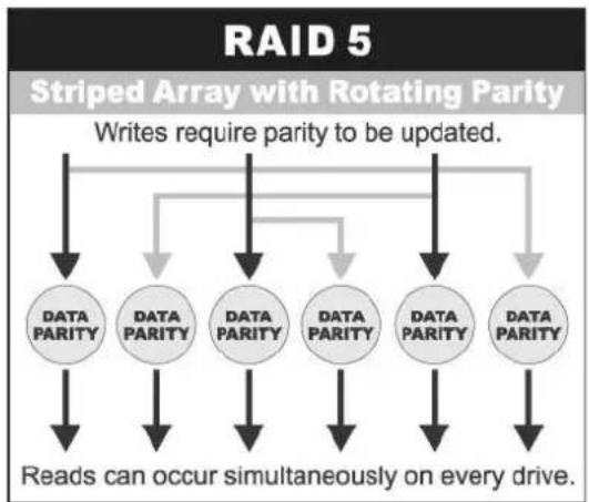
Under RAID 5 parity information is distributed across all the drives. Since there is no dedicated parity drive, all drives contain data and read operations can be overlapped on every drive in the array. Write operations will typically access one data drive and one parity drive. However, because different records store their parity on different drives, write operations can usually be overlapped.
flowchart
graph TD
    A["Reads can occur simultaneously on every drive."] --> B["DATA PARITY"]
    B --> C["Data PARITY"]
    C --> D["DATA PARITY"]
    D --> E["Data PARITY"]
    E --> F["DATA PARITY"]
    F --> G["Data PARITY"]
    G --> H["Data PARITY"]
    H --> I["Data PARITY"]
    I --> J["Data PARITY"]
    J --> K["Data PARITY"]
    K --> L["Data PARITY"]
    L --> M["Data PARITY"]
    M --> N["Data PARITY"]
    N --> O["Data PARITY"]
    O --> P["Data PARITY"]
    P --> Q["Data PARITY"]
    Q --> R["Data PARITY"]
    R --> S["Data PARITY"]
    S --> T["Data PARITY"]
    T --> U["Data PARITY"]
    U --> V["Data PARITY"]
    V --> W["Data PARITY"]
    W --> X["Data PARITY"]
    X --> Y["Data PARITY"]
    Y --> Z["Data PARITY"]
    Z --> AA["Data PARITY"]
    AA --> AB["Data PARITY"]
    AB --> AC["Data PARITY"]
    AC --> AD["Data PARITY"]
    AD --> AE["Data PARITY"]
    AE --> AF["Data PARITY"]
    AF --> AG["Data PARITY"]
    AG --> AH["Data PARITY"]
    AH --> AI["Data PARITY"]
    AI --> AJ["Data PARITY"]
    AJ --> AK["Data PARITY"]
    AK --> AL["Data PARITY"]
    AL --> AM["Data PARITY"]
    AM --> AN["Data PARITY"]
    AN --> AO["Data PARITY"]
    AO --> AP["Data PARITY"]
    AP --> AQ["Data PARITY"]
    AQ --> AR["Data PARITY"]
    AR --> AS["Data PARITY"]
    AS --> AT["Data PARITY"]
    AT --> AU["Data PARITY"]
    AU --> AV["Data PARITY"]
    AV --> AW["Data PARITY"]
    AW --> AX["Data PARITY"]
    AX --> AY["Data PARITY"]
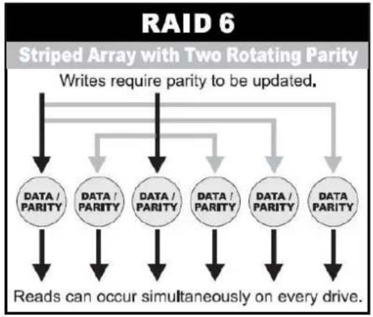
RAID 6 is similar to RAID 5 in that data protection is achieved by writing parity information to the physical drives in the array. With RAID 6, however, two sets of parity data are used. These two sets are different, and each set occupies a capacity equivalent to that of one of the constituent drives. The main advantage of RAID 6 is High data availability – any two drives can fail without loss of critical data.
flowchart
graph TD
    A["RAID 6"] --> B["Striped Array with Two Rotating Parity"]
    B --> C["Data / PARITY"]
    B --> D["DATA / PARITY"]
    B --> E["DATA / PARITY"]
    B --> F["DATA / PARITY"]
    B --> G["DATA / PARITY"]
    B --> H["DATA / PARITY"]
    B --> I["Data / PARITY"]
    B --> J["Data / PARITY"]
    C --> K["Reads can occur simultaneously on every drive."]
    D --> K
    E --> K
    F --> K
    G --> K
    H --> K
    I --> K
    J --> K
    C --> L["Writes require parity to be updated."]
    D --> L
    E --> L
    F --> L
    G --> L
    H --> L
    I --> L
    J --> L
Dual-level RAID achieves a balance between the increased data availability inherent in RAID 1 and RAID 5 and the increased read performance inherent in disk striping (RAID 0). These arrays are sometimes referred to as RAID 0+1 or RAID 10 and RAID 0+5 or RAID 50.
In summary:
♦ RAID 0 is the fastest and most efficient array type but offers no fault-tolerance. RAID 0 requires a minimum of two drives.
♦ RAID 1 is the best choice for performance-critical, fault-tolerant environments. RAID 1 is the only choice for fault-tolerance if no more than two drives are used.
- RAID 5 combines efficient, fault-tolerant data storage with good performance characteristics. However, write performance and performance during drive failure is slower than with RAID 1. Rebuild operations also require more time than with RAID 1 because parity information is also reconstructed. At least three drives are required for RAID 5 arrays.
- RAID 6 is essentially an extension of RAID level 5 which allows for additional fault tolerance by using a second independent distributed parity scheme (two-dimensional parity). Data is striped on a block level across a set of drives, just like in RAID 5, and a second set of parity is calculated and written across all the drives; RAID 6 provides for an extremely high data fault tolerance and can sustain multiple simultaneous drive failures. It is a perfect solution for mission critical applications.
1.4 Array Definition
1.4.1 Drive Group
A Drive Group is a group of physical drives attached to the RAID controller, and where one or more Virtual Drives (VD) can be created. All Virtual Drives in the Drive Group use all of the physical drives in the Drive Group.
It is not possible to have multiple Disk Groups on the same physical disks. If physical disks of different capacity are grouped together in a Drive Group, then the capacity of the smallest disk will become the effective capacity of all the disks in the Drive Group.
1.4.2 Virtual Drive
A Virtual Drive is seen by the operating system as a single drive or logical device. A Virtual Drive is a storage unit created by the RAID controller from one or more physical drives. If there is an existing Drive Group and there is available Free Space, then a new Virtual Drive can still be created.
Depending on the RAID level used, the Virtual Drive may retain redundant data in case of a drive failure.
Chapter 2 Getting Started
2.1 Packaging, Shipment and Delivery
Before removing the subsystem from the shipping carton, you should visually inspect the physical condition of the shipping carton.
- Unpack and verify that the contents of the shipping carton are complete and in good condition.
- Exterior damage to the shipping carton may indicate that the contents of the carton are damaged.
If any damage is found, do not remove the components; contact the dealer where you purchased the subsystem for further instructions.
2.2 Unpacking the NAS System
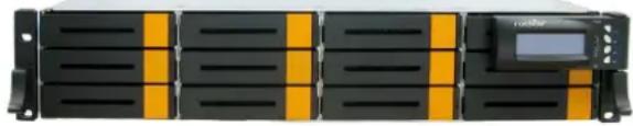
The package contains the following items:
NAS System Unit
natural_image
Front view of a black rack-mounted server unit with yellow and orange ventilation grilles, no visible text or symbols| Two (2) power cords |  |
| Two (2) Ethernet LAN cables |  |
| One (1) RS232 null modem cable (phone jack to DB9) |  |
| Spare screws, etc. |  |
If any of these items are missing or damaged, please contact your dealer or sales representative for assistance.
2.3 Identifying Parts of the NAS System
The illustrations below identify the various parts of the subsystem.
2.3.1 Front View
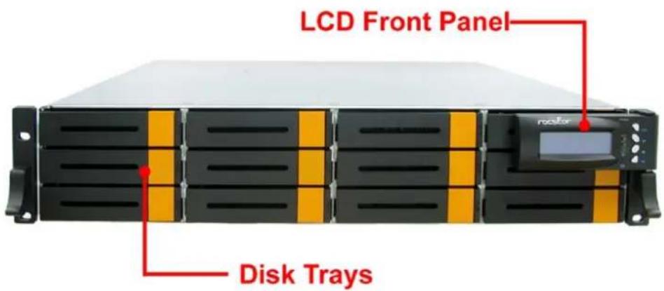
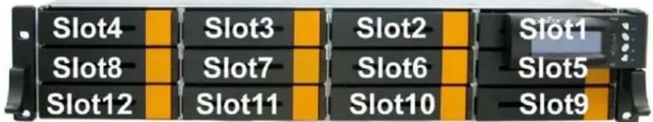
2.3.1.1 LCD Front Panel
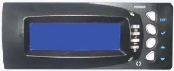
Front Panel
The LCD front panel is an option to setup some system settings. To start using the LCD panel, press the Select button to login and configure the system. See the LCD menu diagram in the next section.
| Parts Function | |
| Exit button EXIT | Press this button to return to the previous menu. |
| Select button √ | This is used to enter the option you have selected. |
| Up and DownArrow buttons | Use the Up or Down arrow keys to go through the information on the LCD screen. This is also used to move between each menu when you configure the system. |
Use the function keys to navigate through the menus in the front panel. The menus will show the system status and allows you to configure network settings, password and mute the alarm buzzer.
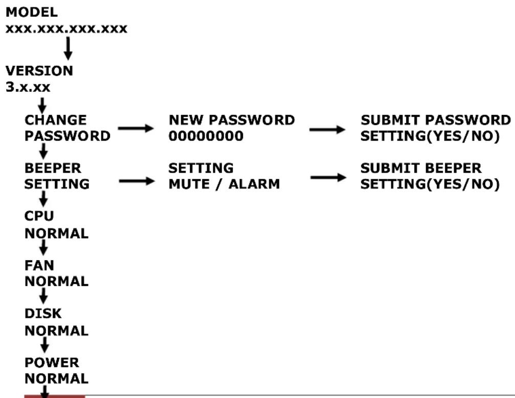
Menu Diagram
flowchart
graph TD
    A["MODEL<br>XXX.XXX.XXX.XXX"] --> B["VERSION<br>3.x.xx"]
    B --> C["CHANGE<br>PASSWORD"]
    C --> D["BEEPER<br>SETTING"]
    D --> E["CPU<br>NORMAL"]
    E --> F["FAN<br>NORMAL"]
    F --> G["DISK<br>NORMAL"]
    G --> H["POWER<br>NORMAL"]
    C --> I["NEW PASSWORD<br>00000000"]
    D --> J["SETTING<br>MUTE / ALARM"]
    I --> K["SUBMIT PASSWORD<br>SETTING(YES/NO)"]
    J --> L["SUBMIT BEEPER<br>SETTING(YES/NO)"]
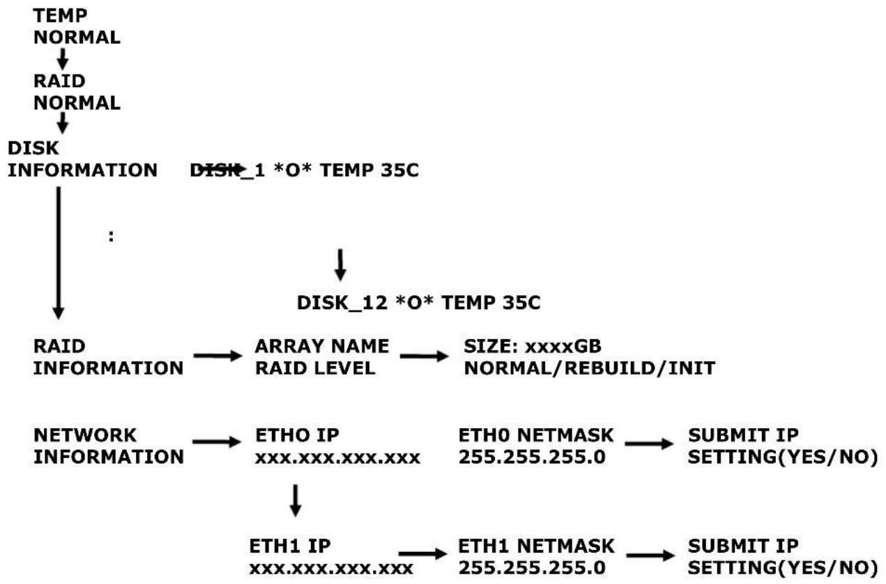
flowchart
graph TD
    A["TEMP NORMAL"] --> B["RAID NORMAL"]
    B --> C["DISK INFORMATION"]
    C --> D["..."]
    D --> E["DISK_1 *O* TEMP 35C"]
    E --> F["DISK_12 *O* TEMP 35C"]
    F --> G["RAID INFORMATION"]
    G --> H["ARRAY NAME RAID LEVEL"]
    H --> I["SIZE: xxxxGB NORMAL/REBUILD/INIT"]
    F --> J["NETWORK INFORMATION"]
    J --> K["ETHO IP xxx.xxx.xxx.xxx"]
    K --> L["ETHO NETMASK 255.255.255.0"]
    L --> M["SUBMIT IP SETTING(YES/NO)"]
    J --> N["ETH1 IP xxx.xxx.xxx.xxx"]
    N --> O["ETH1 NETMASK 255.255.255.0"]
    O --> P["SUBMIT IP SETTING(YES/NO)"]
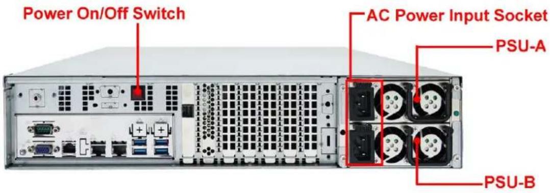
2.3.2 Rear View
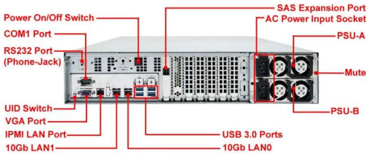
- Power On/Off Switch - Use this switch to power on the system.
-
COM1 Serial Port -The system has one COM1 serial port.
-
RS232 Port (Phone-Jack) – This is used for upgrading the firmware of JBOD Controller SAS Expander board.
- VGA Port - Use this to connect a VGA monitor.
- LAN Ports – The system comes with two 10Gb Ethernet ports LAN0 and LAN1.
- LAN Port LED Indications -There are two LEDs on each LAN port. Please refer to the table below for the LAN port LED indications.
Dedicated IPMI LAN Port LED Indications
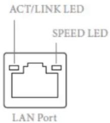
| Activity / Link LED Speed LED | |||
| Status Description Status Description | |||
| Off | No Link | Off | 10M bps connection or no link |
| Blinking Yellow | Data Activity | Yellow | 100M bps connection |
| On | Link | Green | 1Gbps connection |
10G LAN Port LED Indications
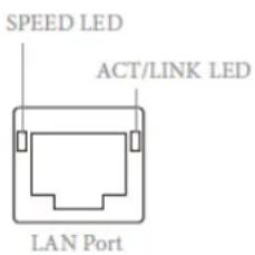
| Speed LED | Activity / Link LED | ||
| Status | Description | Status | Description |
| Yellow | 100Mbps connection or no link | Off | No Link |
| Yellow Blinking | 1Gbps connection | Green | Data Activity |
| Green | 10Gbps connection | On | Link |
-
SAS Expansion Port – For connecting to SAS Expansion Chassis.
-
AC Power Input Socket - Use this to plug in the power cable connected from power source.
-
Power Supply A, B - Two power supplies PSU-A and PSU-B are located at the rear of the NAS System.
-
Mute - Use the mute button to stop the power supply buzzer alarm.
-
USB 3.0 Port – Two USB 3.0 ports are located at the rear of the system. The USB 3.0 port supports the USB 3.0 specification and is compatible to the USB 2.0/1.1 specification.
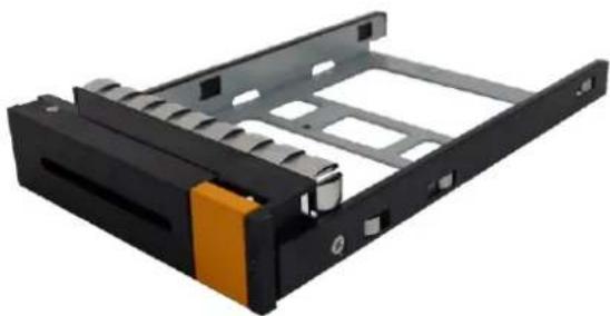
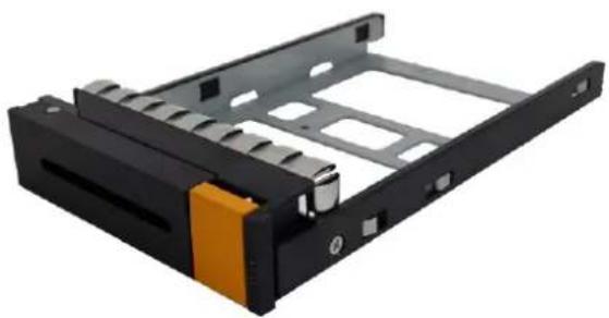
2.4 Drive Carrier Module
The Drive Carrier Module houses a 2.5 inch / 3.5 inch hard disk drive. It is designed for maximum airflow.
natural_image
Black hard drive chassis with orange clamping band and gray internal compartments (no text or symbols visible)2.4.1 Disk Drive Status Indicators
Every Drive Carrier has 2 status indicator lights. The status indicator light is used for Power On/Error. When this light is GREEN the power is on and everything is functioning normally. When the Power On/Error light is RED, then an error has occur that requires the user's attention.
The activity indicator light is the hard disk drive access light. When the hard disk drive is being accessed, this light will flash BLUE.
In addition, both indicator lights are viewable within a 170^ arc.

2.5 Installing Hard Drives
This section describes the physical locations of the hard drives supported by the subsystem and gives instructions on installing a hard drive. The subsystem supports hot-swapping allowing you to install or replace a hard drive while the subsystem is running.
2.5.1 Installing 3.5" Disk in a Disk Tray
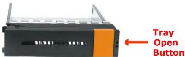
a. Press the Tray Open button and the Disk Tray handle will flip open.
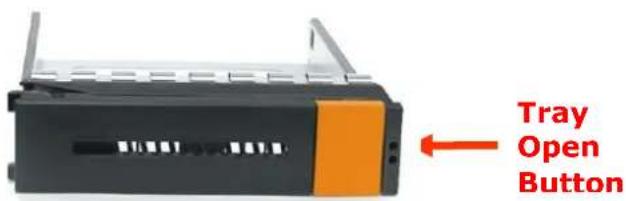
b. Pull out an empty disk tray. Pull the lever handle outwards to remove the carrier from the enclosure.

natural_image
Black hard drive chassis with orange accent and gray internal slots (no text or symbols visible)c. Place the hard drive in the disk tray. Turn the disk tray upside down. Align the four screw holes of the SAS/SATA disk drive in the four Hole A of the disk tray. To secure the disk drive into the disk tray, tighten four screws on these holes of the disk tray. Note in the picture below where the screws should be placed in the disk tray holes.
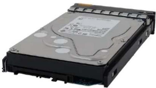
natural_image
Exterior view of a black hard disk drive (no visible text or labels)
NOTE: The mounting hole locations of the new 6-disk are different from the existing drives.
3-, 4-, and 5-disk
6-disk
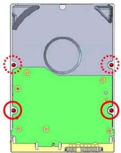
natural_image
Diagram of a computer hard drive casing with green and red highlighted sections, showing mounting holes and mounting points (no text or symbols present)Four bottom mounting holes of drive
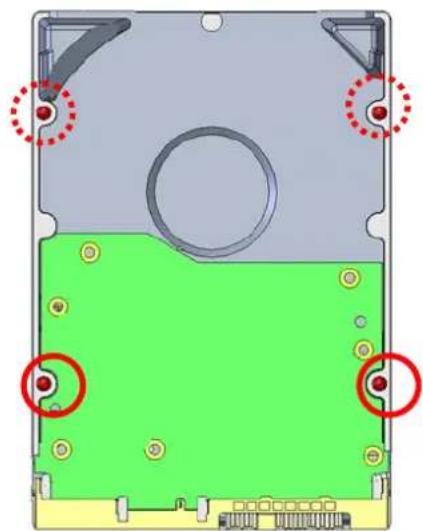
natural_image
Diagram of a hard disk drive casing with green and red circular features, no text or symbols presentFour bottom mounting holes of drive
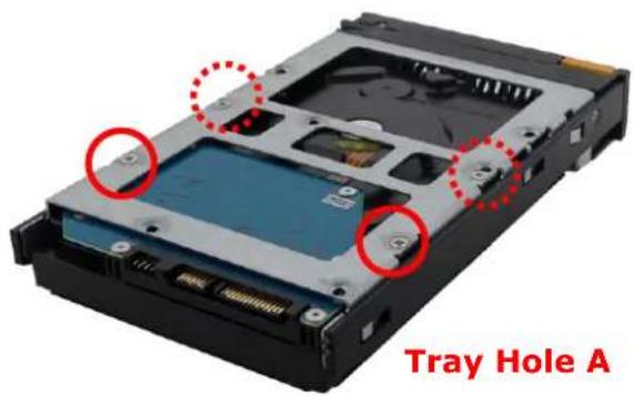
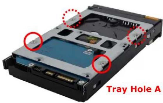

Different screw positions: Comparing 6-Disk Drive to existing Drive

NOTE: All the disk tray holes are labelled accordingly.
d. Slide the tray into a slot.
e. Press the lever in until you hear the latch click into place. The Status LED will turn green when the subsystem is powered on and HDD is good.
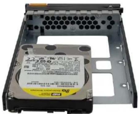
2.5.2 Installing 2.5" Disk in a Disk Tray
a. Press the Tray Open button and the Disk Tray handle will flip open.
b. Pull out an empty disk tray. Pull the lever handle outwards to remove the carrier from the enclosure.
natural_image
Black hard drive chassis with orange and black clamping elements (no text or symbols visible)c. Place the disk drive in the disk tray. Turn the disk tray upside down. Align the four screw holes of the disk drive in the four Hole w of the disk tray. To secure the disk drive into the disk tray, tighten four screws on these holes of the disk tray. Note in the picture below where the screws should be placed in the disk tray holes.
natural_image
Close-up of a black hard disk drive housing with hexagonal top panel and internal label (no readable text or symbols)d. Install the mounting screws on the bottom part to secure the drive in the disk tray.
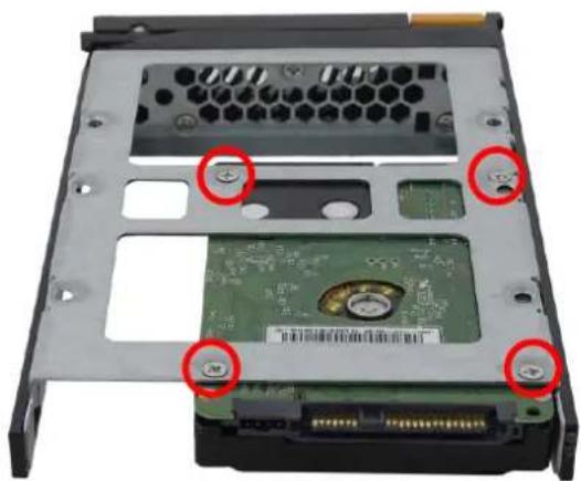
natural_image
Labeled diagram of a hard disk drive showing internal components and mounting holes (no readable text or symbols)Tray Hole W

NOTE: All the disk tray holes are labelled accordingly.
e. Slide the tray into a slot.
f. Press the lever in until you hear the latch click into place. The Status LED will turn green when the subsystem is powered on and HDD is good.
2.6 Preparing the System
-
Attach network cable to Ethernet port LAN0. Connect the other end to your network switch. You may also connect the other Ethernet LAN port if needed.
-
Connect monitor to the VGA port.
-
Connect USB keyboard and mouse or Connect PS/2 keyboard and mouse to the USB-to-PS/2 converter cable, and then connect the USB connector to the USB port on the Server.
2.7 Powering On
- Plug in the two power cords into the AC Power Input Socket of PSU located at the rear of the NAS System.

NOTE: The NAS System is equipped with redundant, full range power supplies with PFC (power factor correction). The system will automatically select voltage.
- Press the Power On/Off Switch to power on the Server.
- The Power LED on the front Panel will turn green.
LIMITED WARRANTY
This Limited Warranty is provided by Rocstorage, Inc. (hereinafter: Rocstor) for all lines of products.
General Terms
EXCEPT AS EXPRESSLY SET FORTH IN THIS LIMITED WARRANTY, ROCSTOR MAKES NO OTHER WARRANTIES OR CONDITIONS, EXPRESS OR IMPLIED, INCLUDING ANY IMPLIED WARRANTIES OF MERCHANTABILITY AND FITNESS FOR A PARTICULAR PURPOSE. ROCSTOR EXPRESSLY DISCLAIMS ALL WARRANTIES AND CONDITIONS NOT STATED IN THIS LIMITED WARRANTY. ANY IMPLIED WARRANTIES THAT MAY BE IMPOSED BY LAW ARE LIMITED IN DURATION TO THE LIMITED WARRANTY PERIOD. SOME STATES OR COUNTRIES DO NOT ALLOW A LIMITATION ON HOW LONG AN IMPLIED WARRANTY LASTS OR THE EXCLUSION OR LIMITATION OF INCIDENTAL OR CONSEQUENTIAL DAMAGES FOR CONSUMER PRODUCTS. IN SUCH STATES OR COUNTRIES, SOME EXCLUSIONS OR LIMITATIONS OF THIS LIMITED WARRANTY MAY NOT APPLY TO YOU.
This Limited Warranty applies to the Rocstor branded hardware products sold by or leased from Rocstorage, Inc., its worldwide subsidiaries, affiliates, authorized resellers, or country distributors (collectively referred to in this Limited Warranty as "Rocstor") with this Limited Warranty. This Limited Warranty is applicable in all countries and may be enforced in any country where Rocstor or its authorized service providers offer warranty service subject to the terms and conditions set forth in this Limited Warranty. However, warranty service availability and response times may vary from country to country and may also be subject to registration requirements in the country of purchase.
Rocstor warrants that the Rocstor hardware product and all the internal components of the product that you have purchased or leased from Rocstor are free from defects in materials or workmanship under normal use during the Limited Warranty Period. The Limited Warranty Period starts on the date of purchase or lease from Rocstor. Your dated sales or delivery receipt, showing the date of purchase or lease of the product, is your proof of the purchase or lease date. You may be required to provide proof of purchase or lease as a condition of receiving warranty service. You are entitled to warranty service according to the terms and conditions of this document if a repair to your Rocstor branded hardware is required within the Limited Warranty Period. This Limited Warranty extends only to the original purchaser or lessee of this Rocstor branded product and is not transferable to anyone who obtains ownership of the Rocstor branded product from the original purchaser or lessee.
Rocstor products are manufactured using new materials or new and used materials equivalent to new in performance and reliability. Spare parts may be new or equivalent to new. Spare parts are warranted to be free from defects in material or workmanship for thirty (30) days or for the remainder of the Limited Warranty Period of the Rocstor hardware product in which they are installed, whichever is longer.
Rocstor's Obligation under the Limited Warranty
During the Limited Warranty Period, Rocstor will repair or replace the defective component parts or the hardware product. All component parts or hardware products removed under this Limited Warranty become the property of Rocstor. The replacement part or product takes on either the Limited Warranty status of the removed part or product or the thirty (30) day limited warranty of the spare part. In the unlikely event that your Rocstor product has a recurring failure, Rocstor, at its discretion, may elect to provide you with a replacement unit of Rocstor's choosing that is at least equivalent to your Rocstor branded product in hardware performance. Rocstor reserves the right to elect, at its sole discretion, to give you a refund of your purchase price or lease payments (less interest) instead of a replacement. This is your exclusive remedy for defective products. The original Limited Warranty is not extended when the product, or a part of the product, is repaired or replaced during the Limited Warranty period. Rocstor shall not be responsible or liable for backing up any data that is on a drive being returned for service
YOU SHOULD MAKE PERIODIC BACKUP COPIES OF THE DATA STORED ON YOUR HARD DRIVE OR OTHER STORAGE DEVICES AS A PRECAUTION AGAINST POSSIBLE FAILURES, ALTERATION, OR LOSS OF THE DATA. BEFORE RETURNING ANY UNIT FOR SERVICE, BE SURE TO BACK UP DATA AND REMOVE ANY CONFIDENTIAL, PROPRIETARY, OR PERSONAL INFORMATION. ROCSTOR IS NOT RESPONSIBLE FOR DAMAGE TO OR LOSS OF ANY PROGRAMS, DATA, OR REMOVABLE STORAGE MEDIA. ROCSTOR IS NOT RESPONSIBLE FOR THE RESTORATION OR REINSTALLATION OF ANY PROGRAMS OR DATA OTHER THAN SOFTWARE INSTALLED BY ROCSTOR WHEN THE PRODUCT WAS MANUFACTURED.
Rocstor does not warrant that the operation of this product will be uninterrupted or error-free. Rocstor is not responsible for damage that occurs as a result of your failure to follow the instructions that came with the Rocstor branded product.
This Limited Warranty does not apply to expendable parts. This Limited Warranty does not extend to any product from which the serial number has been removed or that has been damaged or rendered defective (a) as a result of accident, misuse, abuse, or other external causes; (b) by operation outside the usage parameters stated in the user documentation that shipped with the product and/or posted on the Rocstor website; (c) by the use of parts not manufactured or sold by Rocstor; (d) as a result of normal wear; or (e) by modification or service by anyone other than (i) Rocstor, (ii) a Rocstor authorized service provider, or (iii) your own installation of end-user replaceable Rocstor or Rocstor approved parts if available for your product in the servicing country.
These terms and conditions constitute the complete and exclusive limited warranty agreement between Rocstor and you regarding the Rocstor branded product you have purchased or leased. These terms and conditions supersede any prior agreements or representations including representations made in Rocstor sales literature or advice given to you by Rocstor or an agent or employee of Rocstor-that may have been made in connection with your purchase or lease of the Rocstor branded product. No change to the conditions of this Limited Warranty is valid unless it is made in writing and signed by an authorized representative of Rocstor.
Buyer's Obligation under the Warranty
The person requesting coverage under this warranty shall prove that he or she is the original purchaser and declares that the product has not been sold, leased, bartered or otherwise changed possession. The purchaser shall frequently backup the Enteroc Storage hard drive and backup the data immediately prior to returning the drive for warranty service.
The buyer must notify Rocstor and show proof of notification, through any reasonable means of communication. See Full Street address email address and toll free phone numbers below or updated contact information are available on Rocstor.com website. The notification shall identify any defect, malfunction, or nonconformity promptly upon discovery. Rocstor will acknowledge receipt of the communication and issue a Return Merchandise Authorization (RMA) code. The buyer is obligated to securely and safely package(s) the product, preferably in the original packing materials, WITH THE RMA number, and deliver it together with a copy of the original purchase receipt and a description of the problem to the Rocstor home office. Buyer is responsible for the product until it is received by Rocstor. It is recommended that the product be insured during transportation by the sender. You must prepay any shipping charges, taxes, or duties associated with transportation of the product. In addition, you are responsible for insuring any product shipped or returned for service. You assume risk of loss during shipping.
Limitation of damages (Liability)
IF YOUR ROCSTOR BRANDED HARDWARE PRODUCT FAILS TO WORK AS WARRANTED ABOVE, THE ORIGINAL PURCHASER'S SOLE AND EXCLUSIVE REMEDY SHALL BE REPAIR OR REPLACEMENT. ROCSTOR'S MAXIMUM LIABILITY UNDER THIS LIMITED WARRANTY IS EXPRESSLY LIMITED TO THE LESSER OF THE PRICE YOU HAVE PAID FOR THE PRODUCT OR THE COST OF REPAIR OR REPLACEMENT OF ANY ROCSTOR HARDWARE COMPONENTS THAT
MALFUNCTION IN CONDITIONS OF NORMAL USE. ROCSTOR IS NOT LIABLE FOR ANY DAMAGE TO ANY OTHER PRODUCT CONNECTED TO A ROCSTOR PRODUCT.
Limitation on Consequential Damages
ROCSTOR IS NOT LIABLE FOR ANY DAMAGES CAUSED BY THE PRODUCT OR THE FAILURE OF THE PRODUCT TO PERFORM, INCLUDING ANY LOST PROFITS OR SAVINGS OR SPECIAL, INCIDENTAL OR CONSEQUENTIAL DAMAGES. ROCSTOR IS NOT LIABLE FOR ANY CLAIM MADE BY A THIRD PARTY OR MADE BY YOU FOR A THIRD PARTY. THIS LIMITATION OF LIABILITY ALSO APPLIES WHETHER DAMAGES ARE SOUGHT OR A CLAIM IS MADE UNDER THIS LIMITED WARRANTY OR AS A TORT CLAIM (INCLUDING NEGLIGENCE AND STRICT PRODUCT LIABILITY), A CONTRACT CLAIM OR ANY OTHER CLAIM. THIS LIMITATION OF LIABILITY CANNOT BE WAIVED OR AMENDED BY ANY PERSON. THIS LIMITATION OF LIABILITY WILL BE EFFECTIVE EVEN IF YOU HAVE ADVISED ROCSTOR OR AN AUTHORIZED REPRESENTATIVE OF ROCSTOR OF THE POSSIBILITY OF ANY SUCH DAMAGES.
THIS LIMITED WARRANTY GIVES YOU SPECIFIC LEGAL RIGHTS. YOU MAY ALSO HAVE OTHER RIGHTS THAT MAY VARY FROM STATE TO STATE OR FROM COUNTRY TO COUNTRY. YOU ARE ADVISED TO CONSULT APPLICABLE STATE OR COUNTRY LAWS FOR A FULL DETERMINATION OF YOUR RIGHTS.
Disclaimer
We accept no liability for any loss of data, damages and the inability of Rocstor products to work with any third party equipment. Nor can Rocstor accept any liability or responsibility for software or third party hardware products.
Limited Warranty Period
The limited warranty period for Enteroc Storage is Three (3) Years Parts and Labor. This Limited Warranty extends only to the original purchaser or lessee of this Rocstor branded product and is not transferable to anyone who obtains ownership of the Rocstor branded product from the original purchaser or lessee.
Types of Limited Warranty Service
Your Rocstor Limited Warranty consists of repair or replacement of defective parts, including hard drives identified by Rocstor Support Organization as “pre-failure.”
Carry-in Limited Warranty Service Available Monday - Friday
Under the terms of carry-in service, you may be required to deliver your Rocstor product to the Rocstor Service Center or an authorized service location for warranty repair. You must prepay any shipping charges, taxes or duties associated with transportation of the product. In addition, you are responsible for insuring any product shipped or returned for service. You assume risk of loss during shipping.
YOU SHOULD MAKE PERIODIC BACKUP COPIES OF THE DATA STORED ON YOUR HARD DRIVE OR OTHER STORAGE DEVICES AS A PRECAUTION AGAINST POSSIBLE FAILURES, ALTERATION OR LOSS OF THE DATA. BEFORE RETURNING ANY UNIT FOR SERVICE, BE SURE TO BACK UP DATA AND REMOVE ANY CONFIDENTIAL, PROPRIETARY OR PERSONAL INFORMATION. ROCSTORAGE IS NOT RESPONSIBLE FOR DAMAGE TO OR LOSS OF ANY PROGRAMS, DATA OR REMOVABLE STORAGE MEDIA. ROCSTORAGE IS NOT RESPONSIBLE FOR THE RESTORATION OR REINSTALLATION OF ANY PROGRAMS OR DATA OTHER THAN SOFTWARE INSTALLED BY ROCSTORAGE WHEN THE PRODUCT WAS MANUFACTURED.
Rocstorage shall not be responsible or liable for backing up any data that is on a drive being returned for service. Expect that all data on the drive will be destroyed and not retrievable when returned for warranty service.
Rocstor Replaceable Parts Program
Where available, the Rocstor Replaceable Parts program ships approved replacement parts directly to you to fulfill your warranty. This will save considerable repair time. After you call the Rocstor Technical Support Center at 818.727.7000 a replaceable part can be sent directly to you. Once the part arrives, call the Rocstor Technical Support Center. A technician will assist you over the phone to ensure that the installation is quick and easy.
Service Upgrades
Rocstor offers extra coverage for your product. For information on service upgrades, visit www.rocstor.com. Service upgrades purchased in one country are not transferable to another country.
Capacity Disclaimer
Actual accessible hard drive capacity will indicate up to 10% lower than stated under different Operating Systems and formatting.
The storage volume is measured in total bytes before formatting. References to round numbers of gigabytes or terabytes are an approximation only. For example, a disk drive labeled as having 500GB (Gigabytes) has space for approximately 500,000,000 bytes before formatting. After formatting, the drive capacity is reduced by about 5% to 10% depending on the operating system and formatting used or "1GB = 1,000,000,000 bytes.
Options and Software
The Limited Warranty terms and conditions for Rocstor options are as indicated in the Limited Warranty applicable to Rocstor options. ROCSTOR DOES NOT WARRANTY SOFTWARE PRODUCTS, INCLUDING ANY SOFTWARE PRODUCTS OR THE OPERATING SYSTEM PREINSTALLED BY ROCSTOR. Rocstor's only obligations with respect to software distributed by Rocstor under the Rocstor brand name are set forth in the applicable end-user license or program license agreement. Non-Rocstor hardware and software products are provided "AS IS" and without any Warranty. However, non-Rocstor manufacturers, suppliers or publishers may provide their own warranties directly to you.
The data stored in Rocstor and Rocsecure storage product lines are not guaranteed by Rocstor (or the hard disk manufacturer.) We are not responsible for any loss of data. Always back up data regularly
TECHNICAL SUPPORT
Software Technical Support
Software technical support is defined as assistance with questions and issues about the software that was either preinstalled by Rocstor on the Rocstor branded product or that was included with the Rocstor branded product at the time of your purchase or lease of the product. Technical support for software is available for the first ninety (90) days from date of product purchase or lease. Your dated sales or delivery receipt, showing the date of purchase or lease of the product, is your proof of the purchase or lease date. You may be required to provide proof of purchase or lease as a condition of receiving software technical support. After the first ninety (90) days, technical support for software that was either preinstalled by Rocstor on the Rocstor branded product or included with the Rocstor branded product at the time of your purchase or lease of the product is available for a fee.
WARNING: The individual user should take care to determine prior to use whether this device is suitable, adequate or safe for the use intended. Since individual applications are subject to great variation, the manufacturer
"Rocstor" makes no representation or warranty as to the suitability or fitness of these devices for any specific application.
Technical Support
All Rocstor hard drives are backed by free telephone technical support for three (3) years from the date of purchase. Please register your product with Rocstor. To register, fill in the Limited Warranty Registration form in the Support tab at www.rocstor.com.
Free telephone technical support is available weekdays from 9 AM until 6 PM Pacific Standard Time. Customers in the United States and Canada can call toll-free: (818) 727-7000; all others must call (818) 727-7000.
When calling for support, please have the product's serial number (printed on the label on the bottom of the drive) and system hardware information available.
Trademarks Acknowledgements
© 2017, Rocstorage, Inc; acknowledges the following trademarks for company names or products mentioned within the Rocstor site, portal pages and articles/text/manuals:
Rocstor, Rocsecure and Rocpower are registered trademarks of Rocstorage, Inc. Amphibious, Rocport, Rocbit, Rocsafe, Enteroc are the trademarks of Rocstorage, Inc. "store your future", "secure your future" and "power your future" are the slogan marks of Rocstorage, Inc.
Apple, the Apple logo, Mac, Power Macintosh, FireWire, and Mac Pro, Leopard, Snow Leopard ... are trademarks of Apple Computer, Inc. in the United States and other countries.
Microsoft, MS-DOS, Windows CE, Windows NT, Windows 98, Soft Windows, Vista, Windows 7 ... are registered trademarks of Microsoft Corporation in the United States and other countries.
Intel, Itanium, Pentium XXX, Celeron, and Xeon MMX ... are registered U.S. trademarks of Intel Corporation or its subsidiaries in the United States and other countries.
This product is (may also be) integrated with SATA hard drives from the following manufactures:
Seagate, Samsung, Western Digital, Hitachi, Toshiba, Fujitsu ...
All other names are trademarks of their respective companies.
Rocstor wishes to acknowledge the use of tables, charts, graphs and texts from the Wikipedia website.
© 2000 - 2019
Copyrights
© 2019 Rocstorage, Inc. This Manual is protected by United States copyright law and may not be reproduced, distributed, transmitted, displayed, published or broadcast without the prior written permission of Rocstorage, Inc. You may not alter or remove any trademark, copyright or other notice from copies of this Manual.

natural_image
National flag of the United States, featuring a blue star pattern on the left and white stars on the right (no text or symbols)Designed, integrated and assembled by Rocstor in the U.S.A. using domestic and/or foreign components.
Rocstor is a California Company; U.S.A.
Contact Information
Corporate Headquarters
12979 Arroyo Street, 2nd Floor
San Fernando, California 91340
U.S.A. Office: +1 (818) 727-7000
Email: info@Rocstor.com
Technical Support / RMA
Tel: (818) 727-7000 (USA and Canada)
Tel: +1 (818) 727-7000 (Domestic and
Hours: 9:00 am - 5:00 pm PST
Mon - Fri (excluding holidays)
Email: support@Rocstor.com
Sales Info
Hours: 8:00 am - 5:00 pm PST
Mon - Fri (excluding holidays)
Email: sales@Rocstor.com
Corporate, Government and Academic Customers
Our Corporate Sales Team's goal is to help our U.S.A. and Canadian customers find a storage solution that best serves their needs. We will help you determine your best purchasing options. For more information please contact the appropriate department below or call us at +1 (888) 877-7716
General sales information: sales@Rocstor.com
Corporate sales information: corporate_sales@Rocstor.com
Educational sales information: academic_sales@Rocstor.com
Federal, State & Local government sales information: government_sales@Rocstor.com

- Table of Contents
- Preface 3
- Before You Begin....4
- Chapter 1 Introduction .... 5
- Chapter 2 Getting Started....11
- Preface
- About this manual
- T
- NOTES:
- IMPORTANT!
- WARNING!
- CAUTION:
- Copyright
- Trademarks
- Changes
- Before You Begin
- B
- Upon receiving of the product:
- Upon installing of the product:
- Controller Configuration
- Packaging, Shipment and Delivery
- Chapter 1 Introduction
- Key Features
- Technical Specifications
- RAID Concepts
- RAID Fundamentals
- Disk Striping
- Definition of RAID Levels
- In summary:
- Array Definition
- Drive Group
- Virtual Drive
- Chapter 2 Getting Started
- Packaging, Shipment and Delivery
- Unpacking the NAS System
- Identifying Parts of the NAS System
- Front View
- LCD Front Panel
- Front Panel
- Rear View
- Drive Carrier Module
- Disk Drive Status Indicators
- Installing Hard Drives
- Installing 3.5" Disk in a Disk Tray
- NOTE: All the disk tray holes are labelled accordingly.
- Installing 2.5" Disk in a Disk Tray
- Preparing the System
- Powering On
- LIMITED WARRANTY
- General Terms
- Rocstor's Obligation under the Limited Warranty
- Buyer's Obligation under the Warranty
- Limitation of damages (Liability)
- Limitation on Consequential Damages
- Disclaimer
- Limited Warranty Period
- Types of Limited Warranty Service
- Carry-in Limited Warranty Service Available Monday - Friday
- Rocstor Replaceable Parts Program
- Service Upgrades
- Capacity Disclaimer
- Options and Software
- TECHNICAL SUPPORT
- Software Technical Support
- Trademarks Acknowledgements
- Copyrights
- Contact Information
- Corporate Headquarters
- Technical Support / RMA
- Sales Info
- Corporate, Government and Academic Customers
Brand : Rocstor
Model : Enteroc N1823
Category : Server