Enteroc N1822 - Server Rocstor - Free user manual and instructions
Find the device manual for free Enteroc N1822 Rocstor in PDF.


| Product Type | Network Attached Storage (NAS) Server |
| Model | Rocstor Enteroc N1822 |
| Form Factor | Rackmount, 2U height |
| Dimensions (approx.) | 19 x 25 x 3.5 inches (W x D x H) |
| Weight (approx.) | 30 lbs (13.6 kg) |
| Power Supply | Dual redundant hot-swappable power supplies, 500W |
| Processor | Intel Xeon E5-2403 (1.8 GHz quad-core) |
| Memory | 4 GB DDR3 (expandable) |
| Drive Bays | 18 x 3.5-inch or 2.5-inch SAS/SATA hot-swappable |
| RAID Levels | 0, 1, 3, 5, 6, 10, 50, 60 |
| Supported File Systems | ZFS, XFS, EXT3, EXT4 |
| Network Interfaces | 2 x Gigabit Ethernet (RJ-45) |
| Management | Web browser-based GUI, SNMP, LCD panel |
| Backup Support | Volume clone, snapshot, replication, cloud (Amazon S3), local USB/eSATA |
| Protocols | SMB/CIFS, NFS, AFP, FTP, iSCSI, FC (optional), WebDAV, TFTP, Rsync, Bonjour, SNMP, DHCP, SSH, Telnet |
| Client OS Support | Windows, Unix/Linux, Mac OS |
| Authentication | Local users/groups, Active Directory, NIS, LDAP |
| Power Consumption | Typical 250W (depends on configuration) |
| Operating Temperature | 32°F to 104°F (0°C to 40°C) |
| Certifications | FCC, CE, UL (assumed) |
Frequently Asked Questions - Enteroc N1822 Rocstor
User questions about Enteroc N1822 Rocstor
0 question about this device. Answer the ones you know or ask your own.
Ask a new question about this device
Download the instructions for your Server in PDF format for free! Find your manual Enteroc N1822 - Rocstor and take your electronic device back in hand. On this page are published all the documents necessary for the use of your device. Enteroc N1822 by Rocstor.
USER MANUAL Enteroc N1822 Rocstor
natural_image
Front view of a black rack-mounted server unit with orange ventilation grilles and a digital display (no visible text or symbols)Configuration Guide
Version 1.0
Table of Contents
Preface 4
Chapter 1 Introduction ....5
1.1 Key Features....5
1.2 Technical Specifications....6
Chapter 2 Getting Started With proNAS 3.6 9
2.1 Prepare to Setup NAS 9
2.2 Login NAS Management Webpage by Using Web Browser 9
2.3 Setup and Installation....11
2.3.1 Quick Setup 11
2.3.2 Manually Initializing the NAS Step by Step.... 13
2.4 Connecting to the NAS Share Folder via Network 15
Chapter 3 System Management....17
3.1 Basic Layout of NAS Management GUI.... 17
3.2 Top Shortcut Bar....19
3.3 System Monitoring 21
3.3.1 System Information 21
3.3.2 Resource Monitor 22
3.3.3 System Log 23
3.4 System Manager 24
3.4.1 General 24
3.4.2 Network 26
3.4.3 UPS 34
3.4.4 Event 35
3.4.5 Power....38
3.4.6 Upgrade....39
3.4.7 Tools....40
3.4.8 Schedule Manager....41
3.5 Storage Manager....43
3.5.1 RAID / Array Manager 43
3.5.2 Volume Group Manager 47
3.5.3 iSCSI Manager 56
3.5.4 FC Manager....60
3.5.5 Share Manager....63
3.6 Service Manger....73
3.6.1 Samba service 73
3.6.2 NFS service....75
3.6.3 AFP service 76
3.6.4 FTP service 77
3.6.5 WebDAV service 78
3.6.6 TFTP service....79
3.6.7 Rsync service....79
3.6.8 Bonjour service 80
3.6.9 SNMP service....81
3.6.10 DHCP service....82
3.6.11 SSH service....83
3.6.12 Telnet service 83
3.6.13 File Manager 84
3.7 Account Manager 85
3.7.1 Account 85
3.7.2 Group....91
3.7.3 Directory Service 94
3.8 Backup Manager 97
3.8.1 Data Backup....97
3.8.2 Data Copy 104
3.8.3 Replication Backup 108
3.8.4 Snapshot Backup 113
3.8.5 Volume Clone 118
3.8.6 Rsync Backup 120
3.8.7 System Configuration.... 122
3.8.8 Amazon S3 123
3.9 Attached Device Manager 126
3.9.1 Physical Device 126
3.9.2 ISO Mount 127
3.9.3 iSCSI Initiator 128
3.10 Plug-in Manager.... 130
3.10.1 NAS HA.... 133
3.11 File Manager 148
3.12 General Limitation List 152
Preface
About this manual

his manual provides information regarding the configuration of the NAS 3.6 System. This document also describes the use of the storage management software. Information contained in the manual has been reviewed for accuracy, but not for product warranty because of the various environment/OS/settings. Information and specifications will be changed without further notice. Some pictures and screenshots might be different with the actual machine.
This manual uses section numbering for every topic being discussed for easy and convenient way of finding information in accordance with the user's needs. The following icons are being used for some details and information to be considered in going through with this manual:

NOTES:
These are notes that contain useful information and tips that the user must give attention to in going through with the subsystem operation.

IMPORTANT!
These are the important information that the user must remember.

WARNING!
These are the warnings that the user must follow to avoid unnecessary errors and bodily injury during hardware and software operation of the subsystem.

CAUTION:
These are the cautions that user must be aware of to prevent damage to the equipment and its components.
Copyright
No part of this publication may be reproduced, stored in a retrieval system, or transmitted in any form or by any means, electronic, mechanical, photocopying, recording or otherwise, without the prior written consent.
Trademarks
All products and trade names used in this document are trademarks or registered trademarks of their respective owners.
Changes
The material in this document is for information only and is subject to change without notice.
Chapter 1 Introduction
1.1 Key Features
• Account Manager support NIS
- Allows online capacity expansion within the enclosure
• Android/iOS mobile APP for monitoring
• Backup to Cloud (Amazon S3)
• Backup/Restore from attached storage (USB/eSATA/iSCSI/RDX/USM)
• Backup/Restore from remote share (CIFS/NFS)
• Bonjour Protocol, easily connect to NAS
• Compression (Support on ZFS file system)
• Central data and storage management
• Data backup via backup plan/schedule
- Data copy (1:1)
• Deduplication (Support on ZFS file system)
• EXT4 support extend over 16TB
• HA support Active-Active mode
• HA support iSCSI/FC volume
• HA support Three nodes
• iSCSI/FC/share volume replication
- ISO mount
- Latest volume snapshot technology
• Local and external account management, support large account import
• Online expansion file system
• Plug-in management
• Select share or file for backup/restore
• Share management and permission (support ACL setting)
• Support Fiber target for Fiber SAN (Optional)
• Support Internet Gateway
• Support iSCSI target for IP SAN
• Support iSCSI initiator
• Support iSCSI multi host
• Support e-mail notification, SNMP Trap/MIB and system log
- System configuration backup/restore
• SSD Caching (Read cache, Support on ZFS file system)
- Thin Provisioning
• Volume Clone (EXT3/EXT4/XFS/NTFS/VMFS/ZFS)
• Volume replication to enhance data protection
• Volume switch between iSCSI and FC Target
• VMware ESXi 5 iSCSI/FC/NFS VAAI support
- Wizard-oriented GUI design
• WORM (Write Once Read Many) support CIFS/NFS
1.2 Technical Specifications
| NAS Functionality |
| Storage Management |
| Volume management (Support ZFS, XFS, EXT3 and EXT4 file system) |
| Support SSD Caching, Compression and Deduplication (Support on ZFS file system) |
| Disk usage statistics |
| Hot spare drives |
| iSCSI Target manager: Support LUN Mapping/Initiator Filter/Thin Provisioning |
| FC Target manager: Support LUN Mapping/Thin Provisioning |
| VAAI support for iSCSI/FC/NFS |
| General |
| Independent file server |
| Multiple language support |
| Support UPS |
| Support LV encryption |
| System Management |
| Automatic IP address configuration |
| Web browser-based management |
| SNMP management and notification |
| Fail-free online firmware upgrade |
| Unicode support |
| Multi-node management GUI |
| System configuration backup/restore |
| Central management |
| Quick wizard |
| APP for Android/iOS monitoring |
| Networking |
| Support NIC/Trunking/Load Balance/Fail Over/802.3ad |
| DHCP Server/DHCP Client |
| WINS Server |
| Internet gateway |
| DDNS |
| Protocols |
| TCP/IP, SMB/CIFS, NFS, SNMP, FTP/SFTP/FXP, HTTP, HTTPS, Telnet, SSH, AFP, WebDAV, Bonjour, TFTP |
| Client Operating Systems Support |
| Microsoft® Windows® 98/ME/NT/2000/XP/2003/Vista/2008 /Win7/Windows 2012/Win 8 |
| Unix/Linux |
| Mac OS |
| Authentication |
| Local user account/group |
| Microsoft NT Domain Controller (PDC) |
| Microsoft Active Directory Authentication (ADS) |
| Network Information Service (NIS) |
| Support OpenLDAP service |
| Support creating users by batch |
| User quota management |
| Share level security |
| File level security |
| User ID security for NFS |
| Recycle bin (Samba) |
| File access log, audit (Samba) |
| Write Once Read Many (WORM) |
| Block Storage |
| iSCSI Target Support |
| Fiber Target Support (optional) |
| Thin Provisioning support |
| VMware VAAI support |
| Virtualization |
| VMware/Citrix/Hyper-V |
| VMware VAAI for NFS support |
| Attached Storage |
| ISO Mount |
| USB/eSATA*/iSCSI initiator |
| Data Backup / Restore |
| Volume Clone (EXT3/EXT4/XFS/NTFS/VMFS/ZFS) |
| Symantec BackupExec Agent (by additional installation) |
| Scheduling multi-snapshot (Support iSCSI & FC snapshot) |
| Replication (Remote realtime data mirroring) |
| proNAS High-Availability (Three(3) nodes HA Cluster)(optional) |
| Scheduling Rsync Replication |
| Support NetVault backup client (by additional installation) |
| Support CA ARCserve (by additional installation) |
| Data copy (copy files to other share/attached storage) |
| Scheduling backup |
| Differential/incremental backup |
| iSCSI/FC Replication |
| Amazon S3 backup |
| backup/restore from attached storage (USB/eSATA*/iSCSI/RDX*/USM*) |
| Support Apple Time Machine |
| Plug-in management |
| Anti-Virus |
| Central management |
| iTunes Server |
| Virtualization (VM on NAS) |
* By OEM request
Specification are subject to change without notice.
All company and product names are trademarks of their respective owners.
Chapter 2 Getting Started With proNAS 3.6
2.1 Prepare to Setup NAS
- Before power on, make sure all power cables are plugged.
- Check that LAN cable is connected to LAN_0 port of NAS and is linked.
- To initialize the system, at least one hard drive is needed and inserted in the drive slot.

NOTE: Compatible List of Hard Drive Models
NAS product supports major hard drive brands of 2.5-inch and 3.5-inch SAS / SATA hard drive. Please check Unifosa website:
http://www.proware.com.tw for the latest hard disk drives compatibility list for the NAS.

Important Reminder: Unifosa will not be responsible for any data loss due to incorrect installation or use of hard drive and caused damage to the product under abnormal operation.

Warning: When hard drives that have never been used in the NAS are installed, the hard drives will be formatted automatically when Array is created, and existing data on the hard drives will be cleared.
2.2 Login NAS Management Webpage by Using Web Browser
After power on, please wait for about one minute to boot the system, then the NAS can be managed via web browser at any Windows, Linux, or Mac OS client.
- Open web browser, input http://
in URL bar.
For example: http://172.16.0.1

NOTE:
A. The NAS default IP address is 172.16.0.1.
B. If NAS is set as a DHCP client or you are not sure what IP is used by the NAS, please check the front panel LCD to know the current IP address.
C. Make sure the NAS and the client PC (that you will use to manage the NAS) are on the same subnet.
D. The recommend browsers for management are Google Chrome and Firefox.
- When the login page (Figure 2.2.1) is shown, input user name "admin" and password (default) "00000000". To select the operating language of the management page, select your preferred language on the drop-down list box on the right side.

NOTE: The default admin password might be different in some NAS. Please ask your NAS vendor if you have problem to logon.
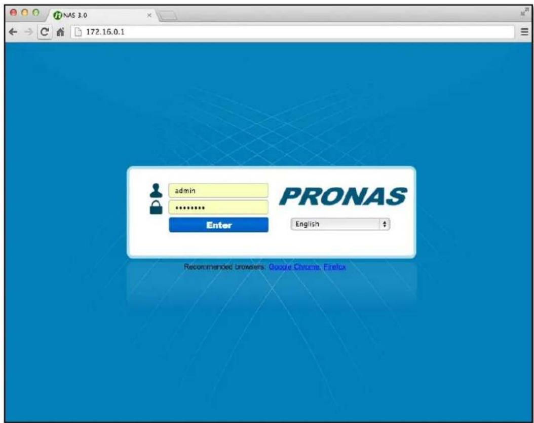
Figure 2.2-1 Login page
- After login, you will see the main NAS management GUI (Figure 2.3.2-1). You can now start to manage or setup the system.
- By default, SSL login is enabled in NAS and allows users to configure and manage the NAS via encrypted transmission. To use this function, you can open the browser then input https://
in URL bar.
For example: https://172.16.0.1

NOTE: If the NAS is behind NAT router or firewall and will use SSL login and remote access from the Internet, open NAT or firewall port 443 to direct to the LAN IP of NAS.
2.3 Setup and Installation
All NAS services and functions are disabled without first initializing the NAS. There are two ways to initialize the NAS, by using Quick Initialization feature or manually step by step.
2.3.1 Quick Setup
After login as "admin" and NAS has not been initialized yet, GUI will pop up a message to ask you to use Quick Initialization feature (Figure 2.3.1-1) to setup the system. The Quick Initialization feature helps you to initialize the NAS in just one page setup. To setup using "NAS Quick Initialization", click "Yes". Then you can start to quickly setup the NAS by providing some information and setting some options, as shown in Figure 2.3.1-2.
If you do not want to use Quick Initialization feature, click "No" in Figure 2.3.1-1. Please note that many functions will be disabled without first initializing the NAS. The Options of Quick Initialization page list next page.
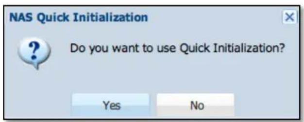
Figure 2.3.1-1 The confirm message to use Quick Initialization
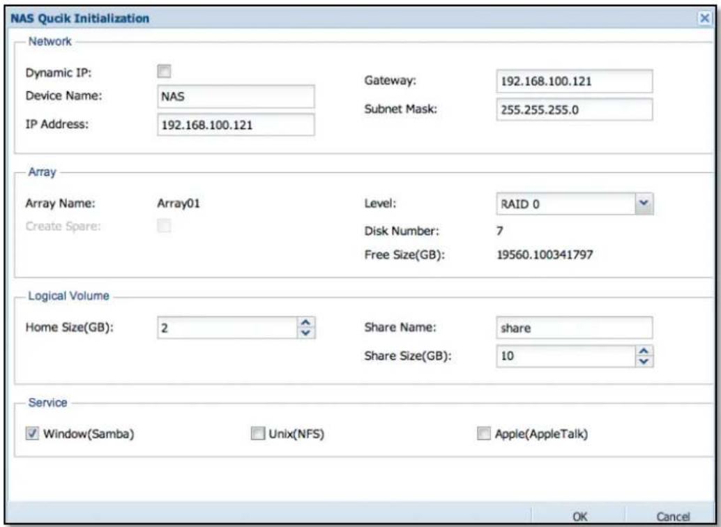
Figure 2.3.1-2 NAS Quick Initialization page
Network
Please modify the options here to match your network environment.
Dynamic IP When enabled, this set the NAS as DHCP client (not suggested)
Host Name Set a unique host name for NAS to be used in network environment.
IP address Set a static IP for LAN_0. (Usually for client connection)
Gateway Set gateway IP for LAN_0.
Subnet Mask Set the Subnet Mask for LAN_0.
Array
The NAS must have at least one Array in order to initialize the system.
Array Name It is fixed to "Array01" for the first Array.
Create Spare Enable this option to reserve a hard drive as a spare disk for Array.
Level Select the RAID Level. Quick Initialization only support RAID levels 0,1,5 and 6.
Disk Number The total number of hard drives detected by the system.
Free Size The estimated size of the Array after it is created.

NOTE: All disks will be the member of Array01. If you plan to create the Array manually, please exit (Cancel) the Quick Initialization and read the Chapter 2.3.2.
Logical Volume
Create a network share folder with specified size for users.
| Home Size(GB) | The default reserved space for user's home folder |
| Share Name | The share folder name that will be accessible to users in the network |
| Share Size(GB) | The volume size of the share folder |
Service
Decide which services need to be enabled after setup, and allow users to connect and access the network share folder(s).
| Window(Samba) | Select this service to enable access for Window users. |
| Unix(NFS) | Select this service to enable access for Unix users. |
| Apple(AFP) | Select this service to enable access for MAC users. |
After filling up all options, click "OK" to execute the setup. This only takes about one minute. After setup is completed, you need to re-login the GUI and customize the detailed configuration. Meanwhile, user can access the share folder via network now.
2.3.2 Manually Initializing the NAS Step by Step
If you would like to create the Array manually, please click "No" in Quick Initialization page (Figure 2.3.1-1). After that, you will see the main NAS information page as shown in Figure 2.3.2-1. Then select "Storage Manager" and "RAID" (refer to Section 3.5.1), and click "Add" to create a customized Array. After Array is created, follow the GUI wizard that will take you to setup NAS by creating Volume Group, Logical Volume, Share or iSCSI step by step.
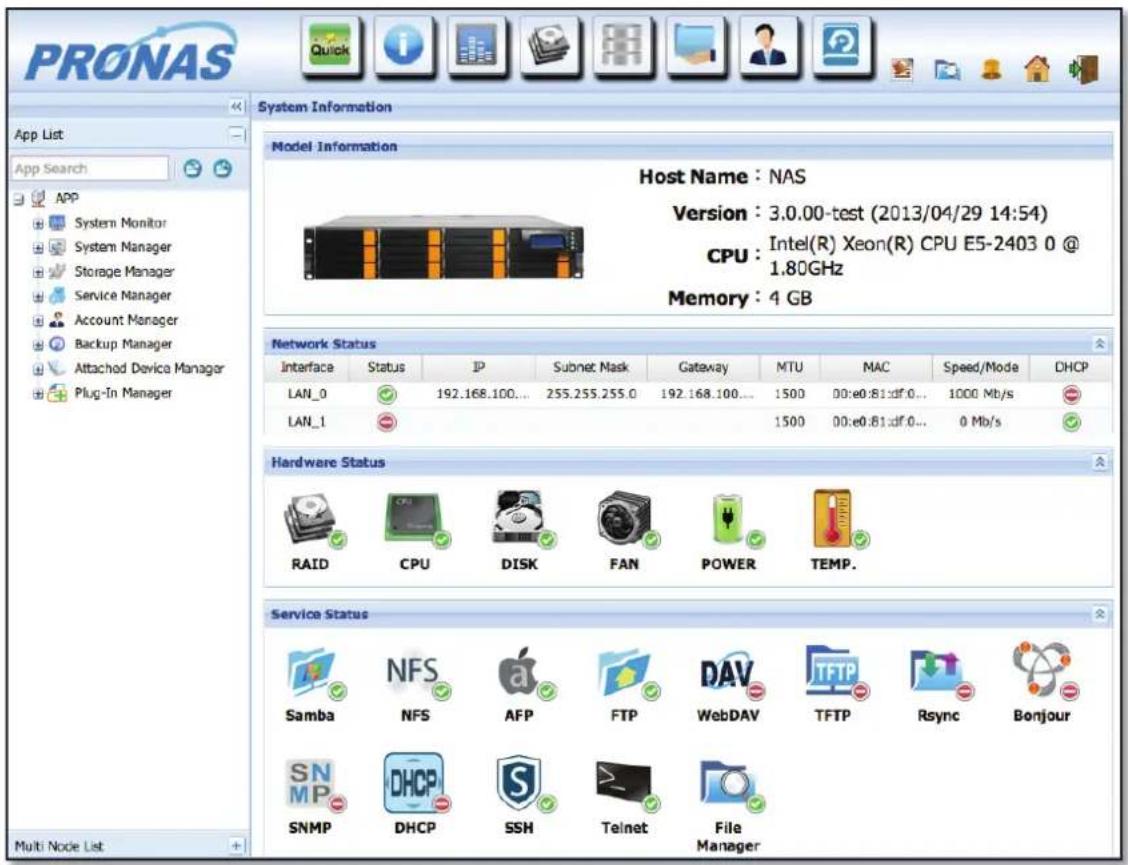
Figure 2.3.2-1 NAS main information page

NOTE: For more information about creating Array, please see Section 3.5.1.
2.4 Connecting to the NAS Share Folder via Network
After NAS is initialized, users can access the share folder from a client PC. Here are the steps to access NAS share folder from clients with different platforms.
Windows Users (SMB/CIFS)
Steps to connect to a NAS share folder:
- Two options to connect to NAS shared folder:
a) Open Network Neighborhood and search Workgroup. If you can't find NAS, search the entire network, double-click the mouse on your workgroup, search for the NAS hostname, and double-click the mouse to connect the NAS.
b) Use the Run function in Windows OS, and enter \NAS-hostname or \NAS-IP to connect to NAS. For example: \NAS or \172.16.0.1
- Enter a valid user name and password:
User name: admin
Password: 00000000
- Select the share folder which you want to connect to.
- You can start to use the NAS share folder, and you can also map the share folder as network drive.
Mac OS Users (SMB or AFP)

NOTE: If AFP is used, make sure AFP is enabled in Service Manager and in Share Protocol.
Steps to connect to a NAS share folder:
- Click 'Go' > 'Connect to Server'
-
Use the following methods to mount the NAS share folder:
Using SMB, input: smb://NAS-IP or smb://NAS-hostname
Using AFP, input: afp://NAS-IP
For example: smb://172.16.0.1 or afp://172.16.0.1 -
Click 'Connect'
-
Enter a valid NAS user name and password (with permission to the share folder),
User name: admin
Password: 00000000
- Click 'Connect'
- Select the NAS share folder you want to be mounted on Mac, and click 'OK'.
Linux Users (NFS)
Steps to connect to a NAS share folder:
Execute the following command in client Linux console:
mount -t nfs
Example:
NAS IP address: 172.16.0.1
Path to NFS Share Folder: /vol/LV_2/nfsshare
Directory to Mount: /mnt/share1
Use the following sample command on the Linux client computer:
mount -t nfs 172.16.0.1:/vol/LV_2/nfsshare /mnt/share1
To check the NAS NFS export list (path to NFS share folders), execute from console of Linux NFS client computer:
showmount -e
Example:
showmount -e 172.16.0.1

NOTE: On the Linux NFS client computer, you must be logged on with the root privileges to be able to mount successfully.
After mounting network share folder of NAS, you access the data on the mounted directory.
Chapter 3 System Management
3.1 Basic Layout of NAS Management GUI
There are 3 parts of the basic layout of NAS GUI, see Figure 3.1-1.
Part 1. Top Menu:
Shortcut Bar contains shortcut buttons of commonly used functions for quick access. Shortcut icon for System Log, File Manager, Buzzer, all APP list and Logout.
Part 2. Left Tree:
App Search: To find out a particular application or function, type the text to search for.
App List: All NAS functions are listed as tree view. You can click 🕒 or click to expand tree view of all function tree.
Multi Node List: As shown in Figure 3.1-2, this lists all detected NAS that are in the same subnet. QLaunch can be downloaded here. QLaunch is a tool to scan and discover all NAS systems in the network.
Part 3. Right Content: This shows the NAS status and settings and configuration options.
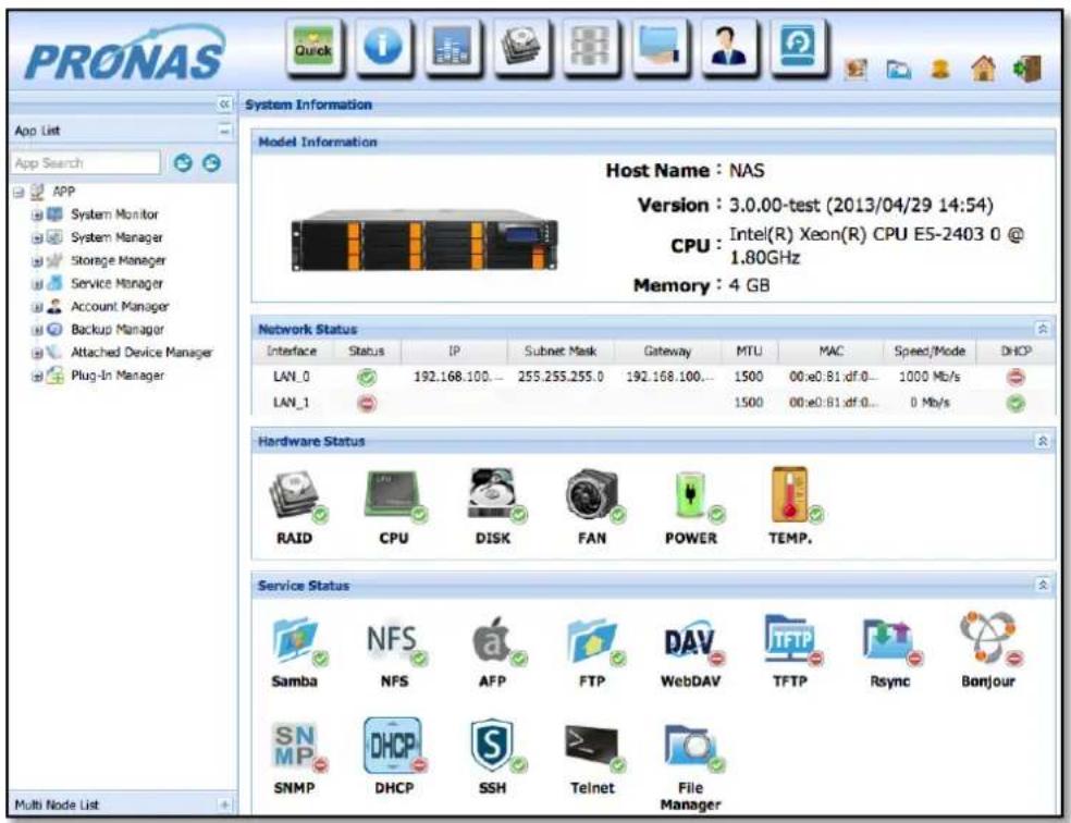
Figure 3.1-1 Basic NAS GUI Layout
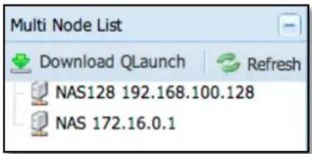
Figure 3.1-2 Multi Node List
You can click "<<" between the tree view and content view (on the upper side) to hide the left tree and change the content view into full mode for better viewing, in some case like viewing in tablet device. (Figure 3.1-3). Click ">>" to change back to normal view.
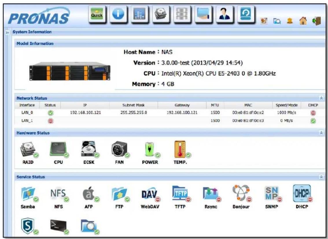
Figure 3.1-3 Hide the tree view list
3.2 Top Shortcut Bar

Figure 3.2-1 Shortcut Bar
Administrators can place frequently used functions in the shortcut bar for quick access.
Default functions in top Shortcut Bar
| Icon | Function Description | |
 | Quick Wizard | Wizard that can be used to setup NAS functions quickly |
 | Information | For viewing the NAS information and status |
 | Resource Monitor | For checking the usage of system resources |
 | Array Manager For creating/editing Array | |
 | Volume Manager | For creating/editing Volume |
 | Share Manager | For create/editing Share folder |
 | Account Manager | For creating/editing Account |
 | Backup Manager | For creating/editing Backup Plan |
Modifying Shortcut Functions in the Shortcut Bar
To Add:
Select the function on the left tree (App List), drag and drop the icon to the top Shortcut Bar. The selected function will be automatically added in the Shortcut Bar. Please note that the maximum number of shortcut icons that can be placed on the Shortcut Bar is 9.
To Remove:
On the Shortcut Bar, press and hold your mouse button on the function icon and drag the mouse cursor anywhere to the right. The selected function will be automatically removed from the Shortcut Bar. Please note that "Quick Wizard" cannot be removed.
There are some small shortcut icons on the top right side of the GUI. There icons are system default and cannot be modified.
| Icon | Function Description | |
 | System Log | For viewing system logs (see Section 3.3.3) |
 | File Manager | This icon enables “admin” user to redirect to the File Manager web page (see Section 3.11) |
 | Buzzer | This is used to enable/disable alarm beeper when hardware event occur. |
 | Home | Show all App List to easily find all functions. (Figure 3.2-2) |
 | Logout Exit the management GUI | |

NOTE: If you do not logout by clicking the Logout icon, you will not be allowed login again on another web browser until the GUI has timed out.
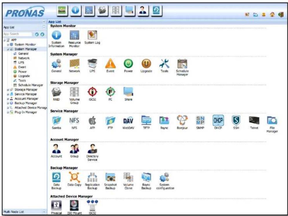
Figure 3.2-2 Home button lists all function
3.3 System Monitoring

System Information
Resource Monitor
System Log
System monitoring provides administrators with information regarding NAS system resources. Admin can also check the system event log, allowing the administrator to be updated with the latest state of the system, and this information can be a basis for adjusting system configurations.
3.3.1 System Information
The System Information provides administrators with information regarding NAS model, network status, hardware status, and service status, as shown in Figure 3.3.1-1.
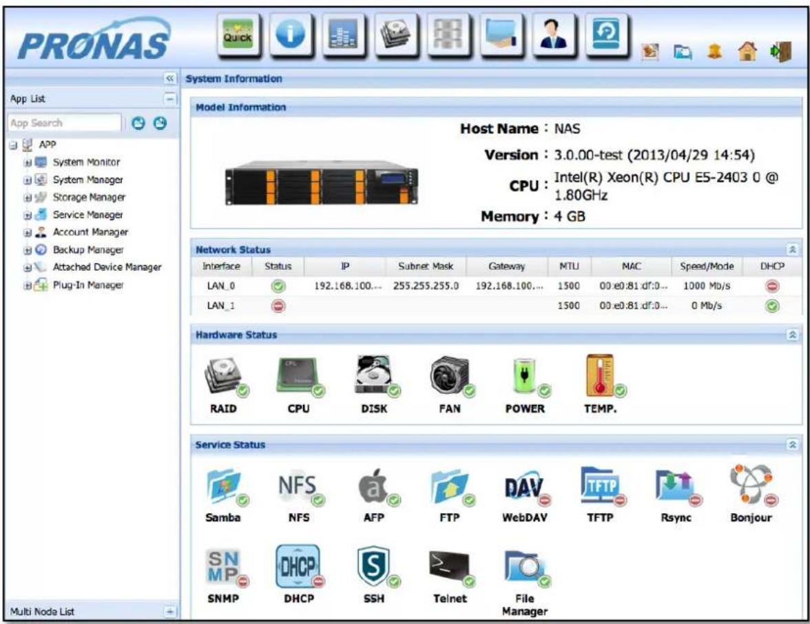
Figure 3.3.1-1 System Information
3.3.2 Resource Monitor
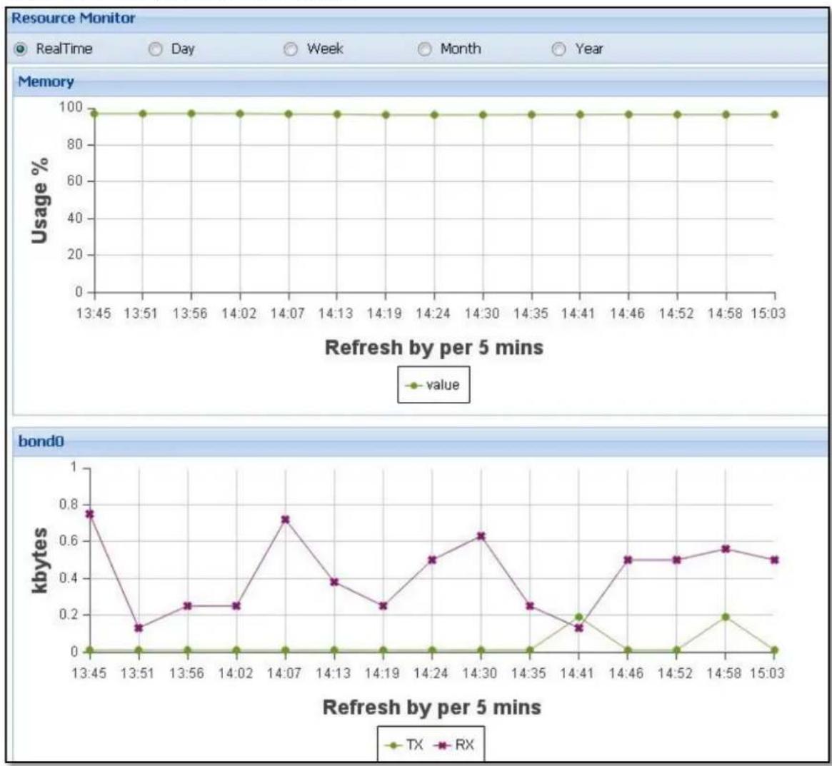
As shown in Figure 3.3.2-1, the Resource Monitor provides graphical information of usage of system resources, such as CPU, memory, and LAN ports. The statistics or usage of various resources are displayed, and updated (refreshed) periodically.
Statistics of System Resources:
line
| Refresh by per 5 mins | Memory Usage % | Bond0 kbytes | | --------------------- | -------------- | ------------ | | 13:45 | 100 | 0.75 | | 13:51 | 100 | 0.12 | | 13:56 | 100 | 0.25 | | 14:02 | 100 | 0.25 | | 14:07 | 100 | 0.72 | | 14:13 | 100 | 0.38 | | 14:19 | 100 | 0.25 | | 14:24 | 100 | 0.50 | | 14:30 | 100 | 0.62 | | 14:35 | 100 | 0.25 | | 14:41 | 100 | 0.12 | | 14:46 | 100 | 0.50 | | 14:52 | 100 | 0.50 | | 14:58 | 100 | 0.55 | | 15:03 | 100 | 0.50 |Figure 3.3.2-1 Resource Monitor
The chart can be shown by RealTime, Day, Week, Month or Year view. (See Figure 3.3.2-1)
3.3.3 System Log
Administrators can view the records of system events in the System Log. Refer to Figure 3.3.3-1. All logs can be filtered by Date, Type and Level.
Type : Event type can be filtered, such as All, System, Storage, Service, Account, Backup, Schedule, and PlugIn.
Level: Level can be filtered such as all, ERROR, WARNING, and INFO.
Download Log: Administrators can save the NAS logs to a local computer. Click "Download log" and the NAS system will save the system log to the computer where NAS webpage was opened. The NAS system log is useful in analyzing NAS systems problems. Administrators can download the system log first and then analyze the logs. The saved log default filename is "NASlog.tgz".
This function is very useful for system trouble shooting.
Clear All Log: Administrator can clear all logs with this button, but it is not recommended.
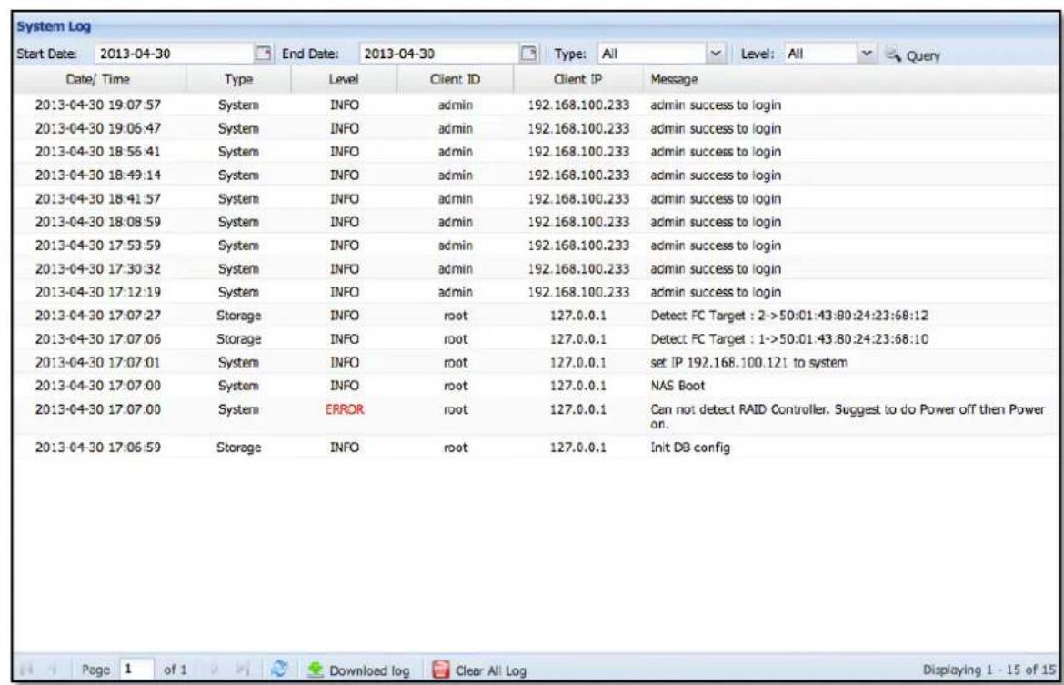
Figure 3.3.3-1 System Log
3.4 System Manager

General

Network

UPS

Event

Power

Upgrade

Tools

Schedule Manager
The System Manager enables NAS administrators to configure system setup such as Date/Time settings, Network settings, UPS settings, Event settings, Power settings, and Schedule Manager, and upgrade the NAS firmware version.
3.4.1 General
In General setting, admin can set or modify the "GUI" and "Date/Time" settings and other related options.
Host Name: Admin can set the NAS Host Name, which can be up to 16 characters and can only contain letters, numbers, hyphen (-) and underscore (_). A space or a period (.) cannot be used. Host name containing numbers only is also not allowed; it must contain at least one non-numeric character. See Figure 3.4.1-1.
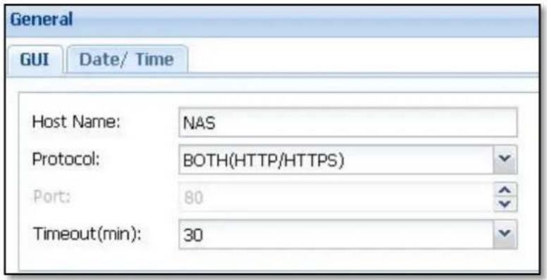
Figure 3.4.1-1 General Setting
Protocol: Default web GUI protocol is set to "Both (HTTP/HTTPS)". There are three possible options: "HTTP", "HTTPS", and "Both (HTTP/HTTPS)".
Port: Default port is set to 80. If changed to another port number, option range is from 1 to 65536.
Timeout (min): Default is 5 minutes, which means admin will be automatically logged out from GUI if there is no activity (idle) in the GUI for 5 minutes. There are four options: 5, 15, 30, and Never. "Never" means no GUI timeout.

NOTE: Don't forget to logout GUI if Timeout is set to "Never", else you cannot login the GUI again from other web browser or PC.
Date/Time
Set up the NAS time and time zone here. See Figures 3.4.1-2 and 3.4.1-3.
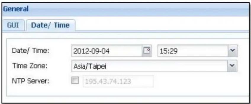
Figure 3.4.1-2 General Date/Time setting
To change the date, click the calendar icon and select the preferred date. To change the time, click arrow-down button in Time option, and select the preferred time.
To set the time zone, click the arrow-down button in Time Zone option, and select the preferred time zone.
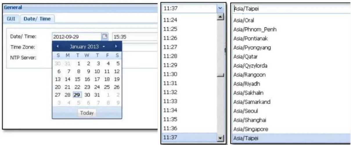
Figure 3.4.1-3 General Date/Time Setting
NTP Server: To enable the NAS to synchronize time from an NTP server, select the NTP Server box (check mark √ will appear) and then enter the NTP server's IP address or fully qualified domain name. See Figure 3.4.1-2. (After NTP Server setting is done, system will sync time from NTP server every 24 hours.)
Sync Local Time to NAS: If you want to synchronize the NAS system time from local time of PC (which you used to login the NAS management GUI), click the "Sync local time to NAS" button.
Apply: After modifying settings, click "Apply" to save changes.
3.4.2 Network
Network management provides options to configure settings such as Adapter, DNS, IPv6, Security, and Routing Table.
Adapter:

Figure 3.4.2-1 Network Setting
Changing Adapter settings:
Edit:
Select interface on the list (Figure 3.4.2-1), for example 'LAN_0' and then click the 'Edit' button. The following screen will be shown (Figure 3.4.2-2).
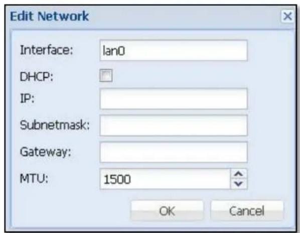
Figure 3.4.2-2 Edit Network Setting
Interface: The LAN Port name. (This name is fixed and can't be modified.)
DHCP: Click the DHCP box to enable DHCP client option (default is disabled). NAS will get a DHCP assigned IP address from a DHCP server, if DHCP server is available.
IP: To use static IP address (DHCP option is not checked), enter the preferred IP address, for example 192.168.1.1. In 'Subnetmask', enter a valid subnet mask, such as 255.255.255.0. In 'Gateway', enter a valid gateway IP address, for example 192.168.1.254.
(Default IP Address / Subnetmask / Gateway are: 172.16.0.1 / 255.255.255.0 / 172.16.0.1)
MTU: Set the Maximum Transmission Unit size of the network packets, in bytes. (Default is 1500)
Trunking:
Trunking enables multiple network interfaces to be combined to form a single channel.
To setup Trunking, click 'Trunking' button, and the following screen will be shown.
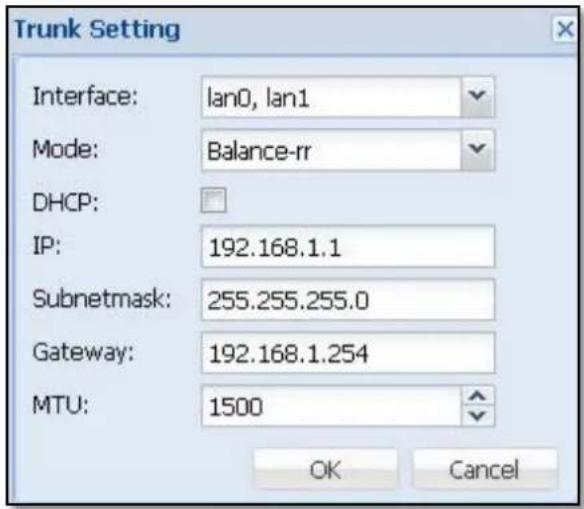
Figure 3.4.2-3 Edit Trunk Setting
Interface: Click the arrow-down button ☑ on the right, and then select which LAN ports will be included in Trunking mode. (This is multiple-choice.) After Trunk Setting setup is done, click "OK".
Mode: Please refer to the following list for options and description of each option.
| Mode | Description | Switch Required |
| Balance-rr(Round-Robin) | Round-Robin mode is good for general purpose load balancing between two Ethernet interfaces. This mode transmits packets in sequential order from the first available slave through the last. Balance-rr provides load balancing and fault tolerance. | Supports static trunking. Make sure static trunking is enabled on the switch. |
| Active Backup | Active Backup uses only one Ethernet interface. It switches to the second Ethernet interface if the first Ethernet interface does not work properly. Only one interface in the bond is active. The bond's MAC address is only visible externally on one port (network adapter) to avoid confusing the switch. Active Backup mode provides fault tolerance. | General switches |
| Balance XOR Balance XOR balances traffic by splitting up outgoing packets between the Ethernet interfaces, using the same one for each specific destination when possible. It transmits based on the selected transmit hash policy. The default policy is a simple slave count operating on Layer 2 where the source MAC address is coupled with destination MAC address. Alternate transmit policies may be selected via the xmit_hash_policy option. Balance XOR mode provides load balancing and fault tolerance. | Supports static trunking. Make sure static trunking is enabled on the switch. | |
| Broadcast Broadcast sends traffic on both network interfaces. This mode provides fault tolerance. | Supports static trunking. Make sure static trunking is enabled on the switch. | |
| IEEE 802.3ad (Dynamic Link Aggregation) | Dynamic Link Aggregation uses a complex algorithm to aggregate adapters by speed and duplex settings. It utilizes all slaves in the active aggregator according to the 802.3ad specification. Dynamic Link Aggregation mode provides load balancing and fault tolerance but requires a switch that supports IEEE 802.3ad with LACP mode properly configured. | Supports 802.3ad LACP |
| Balance-tlb (Adaptive Transmit Load Balancing) | Balance-tlb uses channel bonding that does not require any special switch. The outgoing traffic is distributed according to the current load on each Ethernet interface (computed relative to the speed). Incoming traffic is received by the current Ethernet interface. If the receiving Ethernet interface fails, the other slave takes over the MAC address of the failed receiving slave. Balance-tlb mode provides load balancing and fault tolerance. | General switches |
| Balance-alb (Adaptive Load Balancing) | Balance-alb is similar to balance-tlb but also attempts to redistribute incoming (receive load balancing) for IPV4 traffic. This setup does not require any special switch support or configuration. The receive load balancing is achieved by ARP negotiation sent by the localsystem on their way out and overwrites the source hardware address with the unique hardware address of one of the Ethernet interfaces in the bond such that different peers use different hardware address for the server. This mode provides load balancing and fault tolerance. | General switches |
Default Gateway:

Figure 3.4.2-4 Set Default Gateway to a Network Interface
In the Adapter list in Figure 3.4.2-1, to set Default Gateway, click the arrow-down button on the right (Figure3.4.2-4), and select the interface that will be assigned as default gateway. The NAS system supports only single default gateway interface. The default setting is LAN_0.
DNS:
As shown in Figure 3.4.2-5, NAS system supports up to two DNS server IP address.
To setup DNS server, enter the DNS server IP address in 'DNS Server 1'. If another DNS server will be setup, enter the other DNS server IP address in 'DNS Server 2'.
Apply: After modifying settings, click "Apply" to save changes.
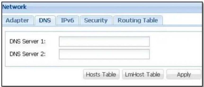
Figure 3.4.2-5 Edit DNS Setting
Hosts Table:
Click "Hosts Table" (see Figure 3.4.2-5) to edit the Hosts Table. The Hosts Table contains mapping of IP addresses to hostnames. (See Figure 3.4.2-6.)
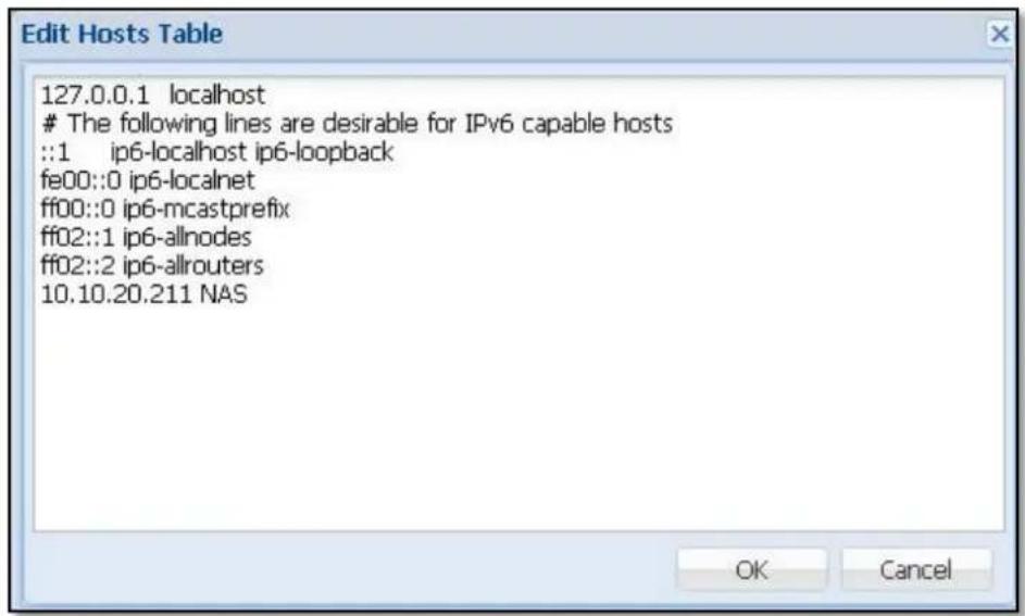
Figure 3.4.2-6 Edit Hosts Table
The Hosts Table can be modified to add IP address and hostname mapping. After editing Hosts Table, click 'OK'.
LmHosts Table:
Click "LmHost Table" (see Figure 3.4.2-5) to edit the LmHosts Table. The LmHosts Table is a mapping of IP addresses to Samba NetBIOS names. It is similar to the Hosts Table, except that the hostname component must correspond to the NetBIOS naming format. (This is optional.)
The LmHosts Table can be modified and add IP address and NetBIOS hostname mapping. After editing LmHost Table, click 'OK'. (See Figure 3.4.2-7.)
OK: After modifying settings, click "OK" to save changes.
Cancel: Click this to undo any changes.
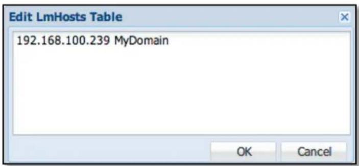
Figure 3.4.2-7 Edit LmHosts Table
IPv6:
By default, IPv6 is set to Disabled, as shown in Figure 3.4.2-8. IPv6 can be enabled by selecting "Enabled". The default IPv6 IP will be displayed in the list after being enabled, as shown in Figure 3.4.2-9.

Figure 3.4.2-8 IPv6 Disabled by default

Figure 3.4.2-9 IPv6 Table after Set to Enabled
Edit:
Select an interface on the list, for example LAN_0, and then click the 'Edit' button. A screen like below will be displayed, and the IPv6 settings can be configured.
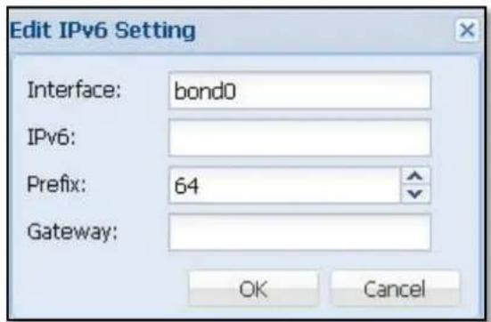
Figure 3.4.2-10 Edit IPv6 Setting
Interface: The LAN Port name. (This name is fixed and cannot be modified.)
IPv6: Enter the IPv6 address which is usually a 128-bit address, divided into eight groups separated by colon “:”, and each address is a hexadecimal digit representing 4-bits.
For example: 2001:0db8:85a3:08d3:1319:8a2e:0370:7344
Other IPv6 formats that can be used are shortened format such as omitting leading zeros or using double colon.
Prefix: Select the prefix.
Gateway: Input IPv6 Default Gateway.
Security:
The Security setting determines which client IP address or range of IP addresses are allowed or rejected access to the NAS resources.
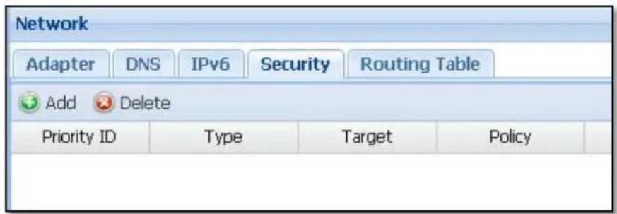
Figure 3.4.2-11 Security Table
Add: Click 'Add' to add a security setting. The screen below will be displayed.
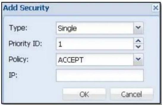
Figure 3.4.2-12 Add Security Table
Type: There are 2 options: Single (for single IP address) or Range (for a range of IP addresses)
Priority ID: This setting allows the NAS system to make a judgment according to the level of Priority ID, with 1 as the highest priority. For example: If an IP address 192.168.1.10 is included in the Range type (192.168.1.1 – 192.168.1.20) and the Priority ID is set to 1 and Policy is ACCEPT (allow access), and the same IP address 192.168.1.10 is set as Single type with Priority ID 2 and Policy is DROP, the higher priority ID 1 will be the effective one, hence the IP address 192.168.1.10 will be allowed access.
Policy: There are 2 options: ACCEPT (allow the IP or range of IP) or DROP (reject the IP or range of IP)
IP: When the Type option is set as Single, enter a single IP address. When the Type option is set as Range, enter the starting IP address and ending IP address for the range of IP addresses.
Routing Table:
Routing Table allows you to setup static routes to specific hosts or networks.
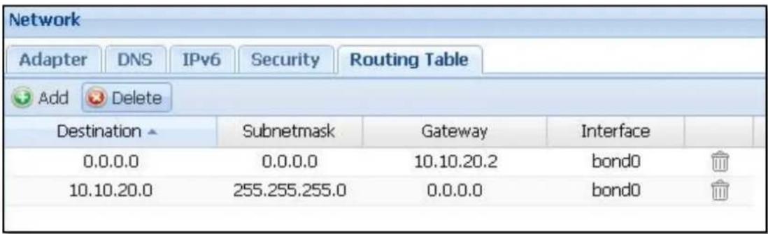
Figure 3.4.2-13 Routing Table
Add: Click 'Add'. The Add Route window will appear.
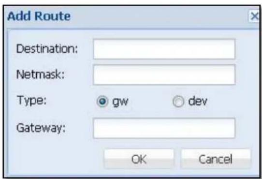
Figure 3.4.2-14 Edit Routing Table
Destination: Please enter the IP address or network range. For example: 192.168.0.1 or 192.168.0.
Netmask: Input a netmask, for example: 255.255.255.0
Type: If "gw" is selected, NAS will use the Gateway for routing packets. If "dev" is selected, NAS will use a LAN interface for routing packets.
Gateway: If "gw" is selected, please enter the gateway IP address. If "dev" is selected, please select a LAN interface.
OK: After modifying settings, click "OK" to save changes.
Cancel: To undo any changes, click "Cancel".
3.4.3 UPS
The NAS system supports UPS (uninterruptible power supply) equipment. (see Figure 3.4.2-5)
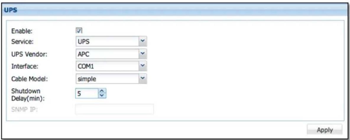
Figure 3.4.3-1 UPS Configuration
Enable: Select (check) this to enable support for UPS.
Service: UPS
UPS Vendor: (For example: APC)
Interface: There are three options for interface connection: COM1, USB, and SNMP.
Cable model: Please select the terminal type.
| Interface | Cable model |
| COM1 simple | smart/ether |
| USB usb | |
| SNMP ether | |
Shutdown Delay (min): Use this to set the delay time in minutes. After a power failure, UPS will shutdown the NAS when the Shutdown Delay time has expired.
SNMP IP: The IP address of APC UPS. This is enabled only when Cable model is set to SNMP.
Apply: After modifying settings, click "Apply" to save changes.
3.4.4 Event
Email setting:
Enable Email notification for sending message when a system failure event occurs.
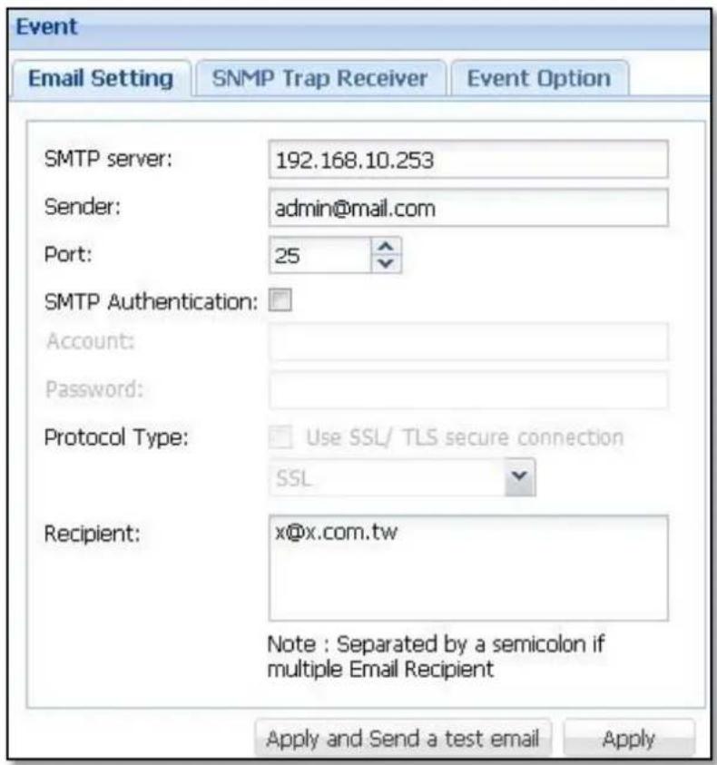
Figure 3.4.4-1 Event Setting
SMTP server: Input the SMTP server's IP address.
Sender: Input the sender's email address.
Port: Enter the port number used by SMTP server. Default port is 25.
SMTP Authentication: If the SMTP server requires authentication using username and password, please select (enable) it.
Account: Enter a valid SMTP account name.
Password: Enter the password of SMTP account name.
Protocol Type: If SMTP server supports SSL/TLS secure connection, please select (enable) it.
Recipient: Please enter the email address of the first email recipient. If there are more than one recipient, please separate them with a semicolon. For example: admin@nas.com; tony@nas.com
Apply and Send a test mail: Use this to save changes, and at the same time send a test email to the recipient(s).
Apply: Click to save changes.
SNMP Trap Receiver :
This setting provides SNMP trap notification by sending message when system failure event occurs.
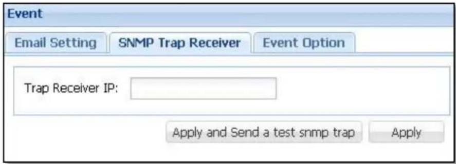
Figure 3.4.4-2 SNMP Trap Setting
Trap Receiver IP: Input here the IP address of SNMP Trap Receiver, i.e. computer running SNMP application that will receive the event messages.
Apply and Send a test snmp trap: Use this to save changes, and at the same time send a test snmp trap to the Trap Receiver.
Apply: Click 'Apply' to save changes.
Event Option: This setting allows you to select which system failure events will be included when messages or event notifications are sent.
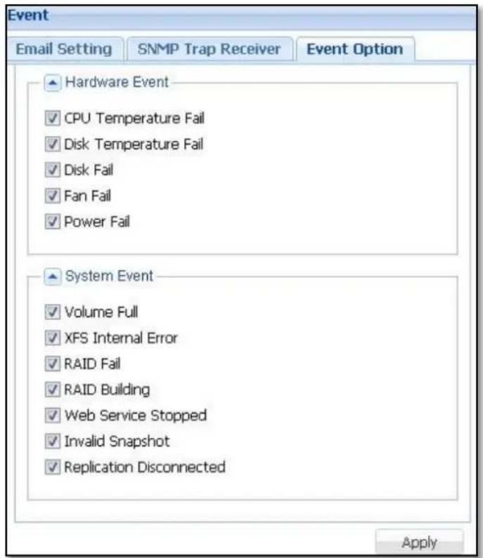
Figure 3.4.4-3 Event Options
Apply: Use 'Apply' button to save changes.

NOTE: The events selected in the Event Option will apply to both Email notification and SNMP Trap notification.
3.4.5 Power
Power provides option to Reboot or Shutdown the NAS system, or to reset the NAS system to factory default by deleting configuration and/or data.
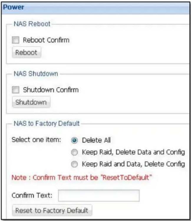
Figure 3.4.5-1 Power Setting
NAS Reboot: Select 'Reboot Confirm' and click 'Reboot' button to reboot the NAS system.
NAS Shutdown: Select 'Shutdown Confirm' and click 'Shutdown' button to shutdown system.
NAS to Factory Default: To reset the NAS system to factory default settings, enter the text "ResetToDefault" in the 'Confirm Text:' box, and then click 'Reset to Factory Default' button.
Description of Options in Resetting to Factory Default:
Delete All: Delete all data, NAS config, and Array.
Keep Raid, Delete Data and Config: Delete NAS configuration and data, but the Array will be retained.
Keep Raid and Data, Delete Config: Delete NAS configuration, but the Array and data will be retained. Only the NAS system settings will be cleared and reverted to the default value. Array information and data will be retained.
The "Reboot" can also be defined with scheduled job in Schedule manager. (See Chap 3.4.8)
3.4.6 Upgrade
This page allows updating the NAS firmware version.
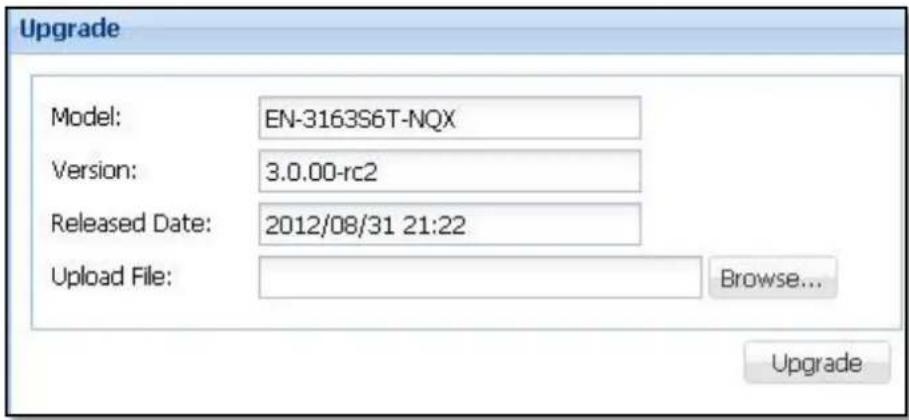
Figure 3.4.6-1 Upgrade
Click the 'Browse...' button and select the firmware file, and then click 'Upgrade'. The firmware file will be automatically uploaded and updated to the NAS system, after which the NAS system will reboot.

NOTE:
A. When NAS is updating, do not power off the NAS to avoid system update failure.
B. When NAS is updating, make sure that the client computers accessing the NAS data (such as share folders) have been disconnected to avoid damaging the data, because during firmware upgrade the NAS system will be rebooted automatically.
C. After upgrade and before re-login GUI, it is better to clear the web browser cache.
3.4.7 Tools
Tools provide the administrator with some useful functions. Select the function and then click 'Query'.
| Tools options | Description |
| Connections Shows current Samba (Windows Client), NFS, AFP (Mac Client), SSH, Telnet, and FTP client connections list. | |
| ps Shows the list of NAS system processes that are currently running. | |
| df Shows the usage information, such as used capacity or free space, of mounted volumes or partitions in the NAS system. | |
| top Shows the NAS system CPU and memory usage and program status. | |
| ping | Can be used to test network connectivity. Enter the IP address to test network connection. |
| dmesg | Shows the kernel messages of NAS system boot-up process. |
| iostat | Shows the current disk device loading information or statistics. |
| netstat Shows various information about the NAS system network connection. | |
| syslog Shows the latest system message log generated by kernel. | |
| Tools | ||||||||
| Connections | ps | df | top | ping | dmesg | iostat | netstat | sysLog |
| Query | ||||||||
| Result | ||||||||
| Active Internet connections (servers and established) | ||||||||
| Proto Recv-Q | Send-Q | Local Address | Foreign Address | State | ||||
| tcp | 0 | 0 0.0.0.0:161 | 0.0.0.0:* | LISTEN | ||||
| tcp | 0 | 0 0.0.0.0:2049 | 0.0.0.0:* | LISTEN | ||||
| tcp | 0 | 0 0.0.0.0:548 | 0.0.0.0:* | LISTEN | ||||
| tcp | 0 | 0 0.0.0.0:37 | 0.0.0.0:* | LISTEN | ||||
| tcp | 0 | 0 0.0.0.0:9734 | 0.0.0.0:* | LISTEN | ||||
| tcp | 0 | 0 0.0.0.0:7 | 0.0.0.0:* | LISTEN | ||||
| tcp | 0 | 0 0.0.0.0:34313 | 0.0.0.0:* | LISTEN | ||||
| tcp | 0 | 0 0.0.0.0:3306 | 0.0.0.0:* | LISTEN | ||||
| tcp | 0 | 0 0.0.0.0:13 | 0.0.0.0:* | LISTEN | ||||
| tcp | 0 | 0 0.0.0.0:111 | 0.0.0.0:* | LISTEN | ||||
| tcp | 0 | 0 0.0.0.0:44112 | 0.0.0.0:* | LISTEN | ||||
| tcp | 0 | 0 0.0.0.0:22 | 0.0.0.0:* | LISTEN | ||||
| tcp | 0 | 0 0.0.0.0:23 | 0.0.0.0:* | LISTEN | ||||
| tcp | 0 | 0 127.0.0.1:4700 | 0.0.0.0:* | LISTEN | ||||
| tcp | 0 | 0 0.0.0.0:60253 | 0.0.0.0:* | LISTEN | ||||
| tcp | 0 | 0 0.0.0.0:44445 | 0.0.0.0:* | LISTEN | ||||
| tcp | O | O 0.0.0.0:445 | O.O.O.O:* | LISTEN | ||||
| tcp | O | O :::50887 | ::::* | LISTEN | ||||
| tcp | O | O :::111 | ::::* | LISTEN | ||||
Figure 3.4.7-1 Tools
3.4.8 Schedule Manager
This function allows administrators to control scheduled tasks in the NAS. There are 5 Types of funtions that can be set with schedule: Data Backup, Data Copy, Snapshot, Rsync and Power (Restart/ON/OFF).
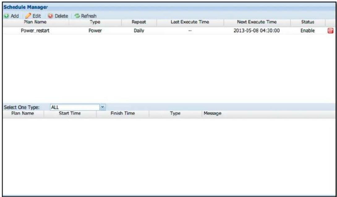
Figure 3.4.8-1 Schedule Manager
Add Schedule: Click 'Add' button. The setup screen below will appear.
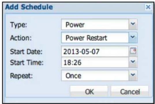
Figure 3.4.8-2 New Schedule Task
Type: This field has five options: Data Backup, Data Copy, Snapshot, Rsync and Power.
Plan Name: Select the name of the backup plan (available only in Data Backup, Data Copy, Snapshot, and Rsync).
Action: Select the type of action for the schedule, such as Power Restart, Power ON, or Power OFF (available only in Power).
Start Date: Select the date when to start backup. Please select current date or a future date.
Start Time: Select the time when to start backup. This field is a 24-hour clock.
Repeat:
| Option | Description |
| Disabled | Disables the backup schedule. When you need to temporarily turn off this schedule, you can use this option to pause the backup schedule. |
| Once | This option will perform a one-time backup based on the set date and time. This option will change to Stop when this scheduled backup has run once. |
| Hourly | The hourly schedule will be based on the start date and time. Every hour, the scheduled backup will be executed. |
| Daily | The daily schedule will be based on the start date and time. The scheduled backup will be performed daily. |
| Weekly | The weekly schedule will be based on the start date and time. The scheduled backup will be executed weekly. |
| Every 2 weeks | Every two weeks schedule will be based on the start date and time. Scheduled backup will be performed once every two weeks. |
| Monthly | The monthly schedule will be based on the start date and time. Once a month, the scheduled backup will be performed. |
| Yearly | The annual schedule will be based on the start date and time. Every year, the scheduled backup will be executed. |

NOTE:
A. The same backup plan name cannot be selected to have different schedule settings.
B. When setting backup schedule, the past date and time cannot be selected.
C. Setting scheduled tasks with time too close to each other is not recommended.
Edit schedule: Select a schedule and click 'Edit' to modify schedule, such as the Start Date, Start Time, and Repeat settings.
Delete a schedule: Click 📋 at the right column of the plan to be deleted.
3.5 Storage Manager
This page allows administrators to do Array (RAID) configuration and disk allocation, and management of Volume Groups and Logical Volumes, iSCSI and FC volumes, and Share folders.
3.5.1 RAID / Array Manager
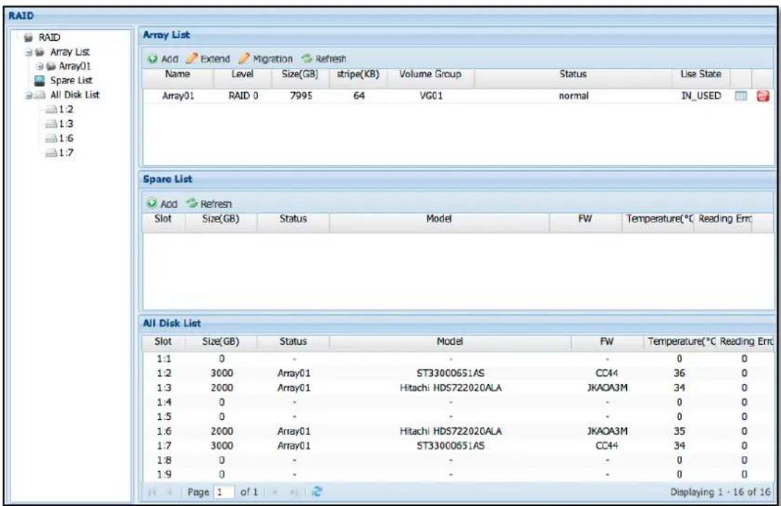
Figure 3.5.1-1 Array Manager
Functions on Array Manager (left pane):
Array List:
A. Displays the list of existing Arrays, and the member hard disks in each Array B. After selecting the Array List option, on the right pane you can select an Array and do Add/Extend/Delete Array operation.
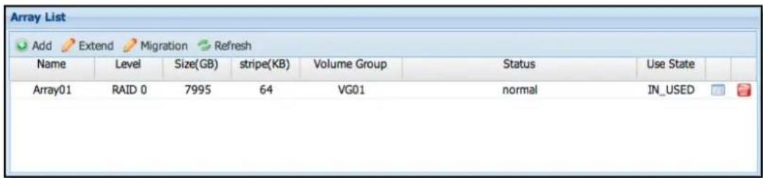
Figure 3.5.1-2 Array List
Add: Press 'Add' button. The Add Array window will appear.
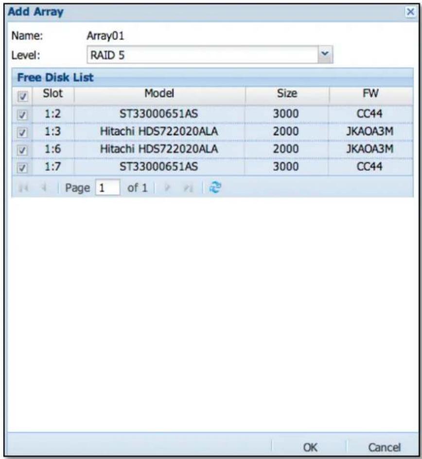
Figure 3.5.1-3 Add Array
Name: Displays the Array name. System will automatically generate an Array name and can't be modified.
Level: Select the RAID Level for the Array. The NAS supports RAID levels 0, 1, 3, 5, 6, 10, 50 and 60 (by selected model). The detailed information of each RAID level is described in the succeeding page.
Free Disk List: This is the list of unused hard disks. Administrator can select which hard disk to include in the Array.
Slot: Shows the Chassis ID: hard disk slot number
For example: 1:9 is the first chassis (usually the NAS chassis itself) and 9th slot hard disk
Model: The hard disk model
Size: The hard disk capacity; unit is gigabytes (GB).
FW: The hard disk firmware version.
Extend Array: Select the Array name then click 'Extend' button, and then choose an unused hard disk that will be used for Array expansion.

NOTE:
a. If an Array is already in use (has been assigned to a volume group), this Array cannot be deleted.
b. If initialization of new Array is completed, but new Array does not appear in the list, click 'Refresh' or 'to update the Array List.
Delete Array: On the left pane, select 'Array List' under 'Array Manager' (RAID), then on the Array List on right pane click the delete icon 📋 on the right side of the Array to be deleted.
Before deleting an Array, please make sure that the selected Array is not in use, such as Array is included in a volume group. If Array is included in a VG, delete first the VG. After VG is deleted, then the Array can be deleted.
If a VG contains existing logical volume(s) and share folder(s), delete first the share folder(s) and logical volume(s), and then delete the VG and the Array.
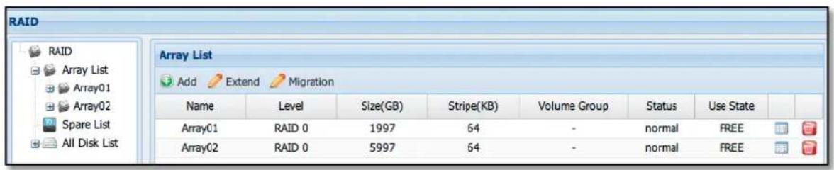
Figure 3.5.1-4 Array Manager (RAID)
After clicking the delete icon, a confirmation window will appear to confirm deletion of selected Array. Select the 'Confirm:' box and click the 'Yes' button to confirm the deletion of Array. System will delete the selected Array.
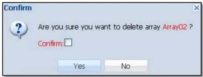
Figure 3.5.1-5 Confirm Message to Delete an Array

Figure 3.5.1-6 Spare List
Spare List: On the right pane, the Spare List (Figure 3.5.1-6) will show the list of Hot Spare hard disks. You can add an unused hard disk as Hot Spare.
Add Spare: Click 'Add', select a hard disk, and click 'OK' button. In Confirm window, select the 'Confirm:' box and click 'Yes'. The hard disk will be set as Hot Spare.
Delete Spare: To delete a Hot Spare hard disk and make it as unused hard disk, click the delete 📋 icon on the right of the Hot Spare hard disk.
After that, the confirmation window will appear (Figure 3.5.1-7). To confirm deletion of Hot Spare hard disk, check the 'Confirm:' box and click the 'Yes' button. The selected Hot Spare hard disk will become unused hard disk.
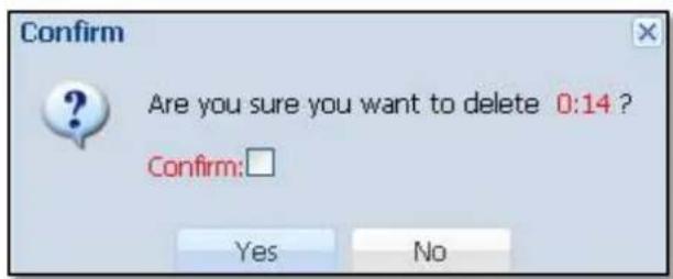
Figure 3.5.1-7 Confirm Message to Delete a Spare Disk
All Disk List: After selecting this option, a list of all hard disks and hard disk status will be shown on the right pane.
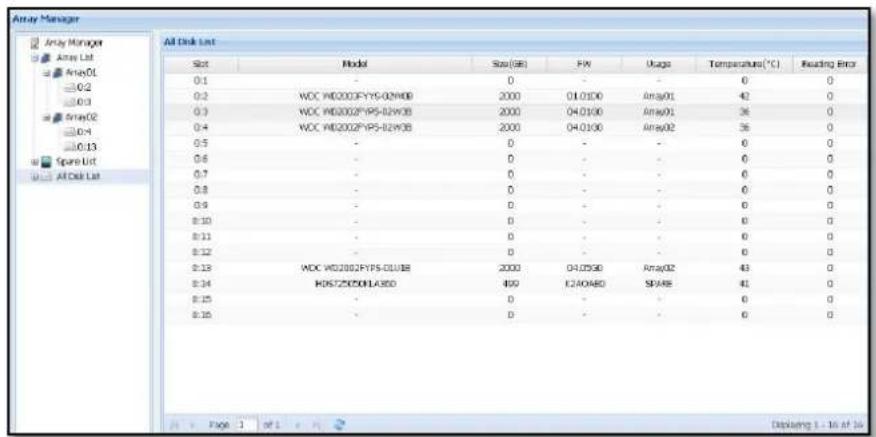
Figure 3.5.1-8 All Disk List
3.5.2 Volume Group Manager
Volume Group (VG) is a storage pool for creating logical volumes. You need to create at least one VG (first VG is VG01) by adding an Array (for example Array01) to initialize the NAS system and enable NAS functions.

Figure 3.5.2-1 Volume Group Manager
Add: To add a Volume Group, click 'Add' button, and then select the Array name to be included in the VG and click 'OK' button. The NAS system will automatically create the new Volume Group.
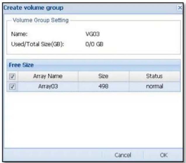
Figure 3.5.2-2 Create a new Volume Group
Insert Array: To expand the size of a Volume Group, select the Volume Group name and click 'Insert RAID' button. Select the Array name that will be joined to the VG, and then click 'OK'. In Confirm window, select the 'Confirm:' option and click 'Yes'. The NAS system will automatically expand the size of the selected VG using the added Array.
Remove Array: To remove an Array from a Volume Group, select the Volume Group name and click 'Remove RAID', and then click 'OK' button. In Confirm window, select the 'Confirm:' option and click 'Yes'. The NAS system will automatically remove the selected Array from the VG, and the VG size will be reduced accordingly.
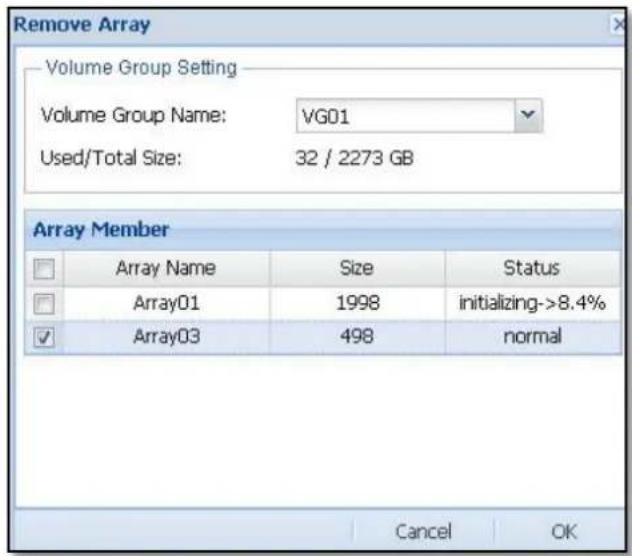
Figure 3.5.2-3 Remove Array
Add: To create a Logical Volume (LV) from a Volume Group
a. Select first the Volume Group name (VGXX) where a Logical Volume will be created, and then click the 'Add' button under Logical Volume List.
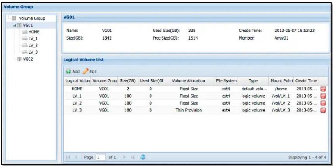
Figure 3.5.2-4 Volume Group Status
b. The 'Add Logical Volume' window will appear. Enter the logical volume name, change the Volume Group Name where the LV will be created if necessary, select the file system format for the LV, and set the LV size. Click 'OK' when done.
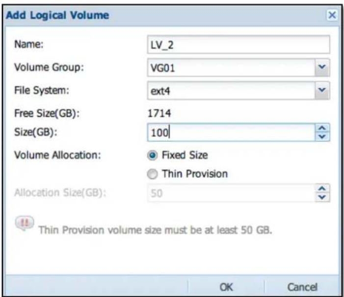
Figure 3.5.2-5 Creating a Fixed Size Logical Volume
Name: The NAS system will automatically generate a default LV name 'LV_x' where x is a number in series starting from 1, such as LV_1. The LV name can also be modified if needed.
Volume Group Name: Click the arrow-down button on the right, and a drop-down menu will appear where a volume group name can be selected.
Free Size(GB): This displays the selected volume group's unused capacity.
File System: Select the file system format for the LV, default is ext4. Format options are described below.
| Format | Description |
| ext3 | This file format is suitable for small I/O, average single-file size of about 4KB-50MB. |
| ext4 | This file format is suitable for big I/O, average single-file size of about 4KB-128MB |
| xfs | This file format is suitable for big I/O, average single-file size of about 128MB-1GB or above |
| zfs | This file format is suitable for big I/O, average single-file size of about |
128MB-1GB or above, also support compression de-duplication and SSD caching

NOTE: The LV Name only allows up to 32 characters, and can only contain letters, numbers, hyphen (-) and underscore (_).
Size(GB): The size of Logical Volume to be created must be based on the "Free Size (GB)" field, size must be less than the Volume Group available capacity.
Volume Allocation options:
Fixed Size: Create a logical volume with fixed physical size.
Thin Provision: Create a Thin Provisioning pool with Size, and create a Thin Provisioning volume with Allocation Size (option below).
Allocation Size(GB): This field is enabled only when creating LV with Thin Provision. The minimum size of a Thin Provisioning volume is 50GB, and the maximum size is 32TB or 4 times of physical volume size.

Figure 3.5.2-6 Create a Thin Provisioning Logical Volume
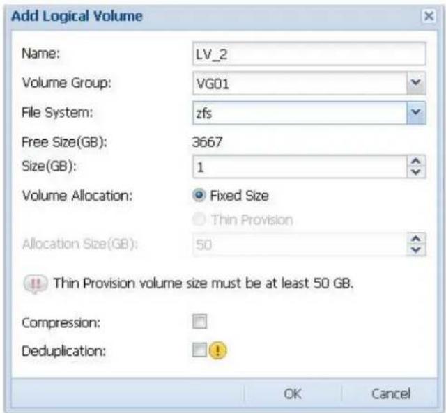
Figure 3.5.2-7 Create a ZFS Logical Volume
Compression: This allows tradeoffs between the amount of CPU required for compression and the resulting compression efficiency. Compression also provides increased throughput and performance within the system due to the fact that less data is being written to and read from disk, resulting in fewer I/O operations.
De-duplication: If a file system has the dedup property enabled, duplicate data blocks are removed as they are written to disk. The result is that only unique data is stored on disk and common components are shared between files.
Expanding Logical Volume Capacity:
Select a Logical Volume that need to be expanded in the Logical Volumes List (See Figure 3.5.2-4) and click 'Edit', change the "Logical Volume Size (GB)" to the preferred size, and then click 'Apply'. In Confirm window, select the "Confirm:" option and click 'Yes'. The Logical Volume size will be expanded automatically.
If the volume set as a Thin Provision Volume, you can also modify the field "Thin Provision Size" here (See Figure 3.5.2-8).
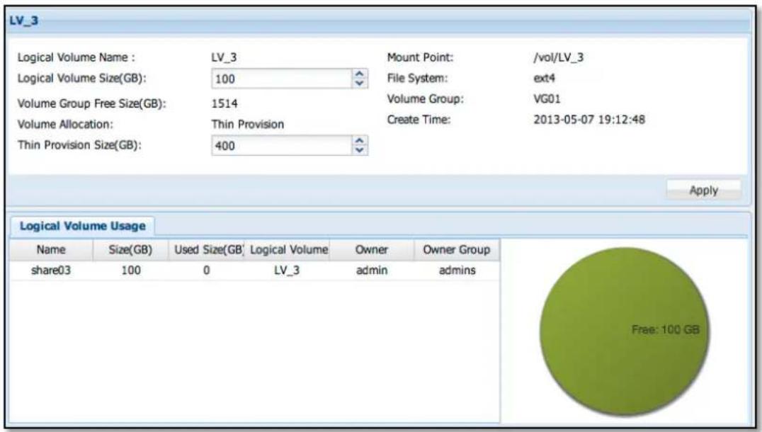
Figure 3.5.2-8 Logical Volume Information

NOTE:
- The logical volume size can only be expanded, but cannot be reduced.
- It might take time to expand a volume with file system.
Volume Encryption:
In each logical volume information, if share folders have not been created yet in the logical volume, as shown in Figure 3.5.2-9, the volume can be encrypted by clicking "Encrypt" and then typing the password. After an encrypted volume is created, system will download the key file automatically. Please keep the key file safely. The volume data will become invalid without key file.
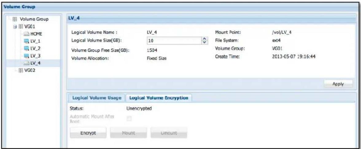
Figure 3.5.2-9 Creating an Encrypted Logical Volume
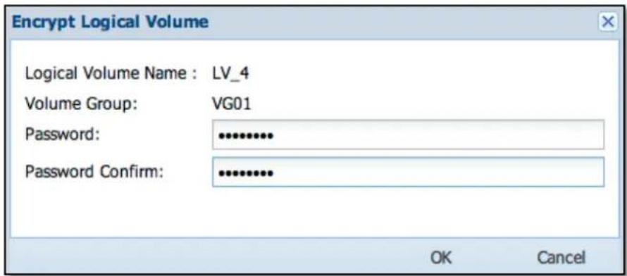
Figure 3.5.2-10 Set Password for the Encrypted Logical Volume
The volume will not be mounted automatically after encryption. You can mount the encrypted volume manually by clicking "Mount" (Figure 3.5.2-11) and input the password. Then the encrypted volume will be mounted 📄 and ready to use (Figure 3.5.2-12).
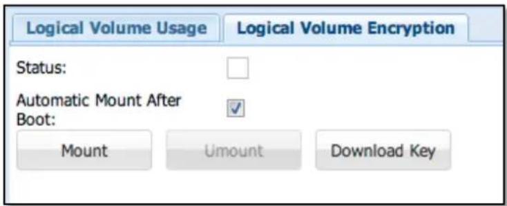
Figure 3.5.2-11 Encrypted Logical Volume in Un-mounted State
Automatic Mount After Boot:
Default is enabled. The volume will be automatically mounted after boot without typing the password. If disabled, you have to manually mount the volume and type password after every boot.
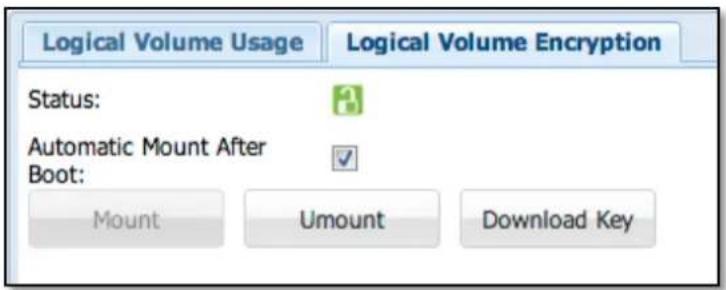
Figure 3.5.2-12 Encrypted Logical Volume in Mounted State
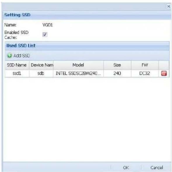
SSD cache: (support by zfs)
Frequently accessed data is stored in RAM, and less frequently accessed data can be stored on slower media, such as SSD disks. Data that is not often accessed is not cached and left on the slow hard drives. If old data is suddenly read a lot, NAS will automatically move it to SSD disks or to RAM.
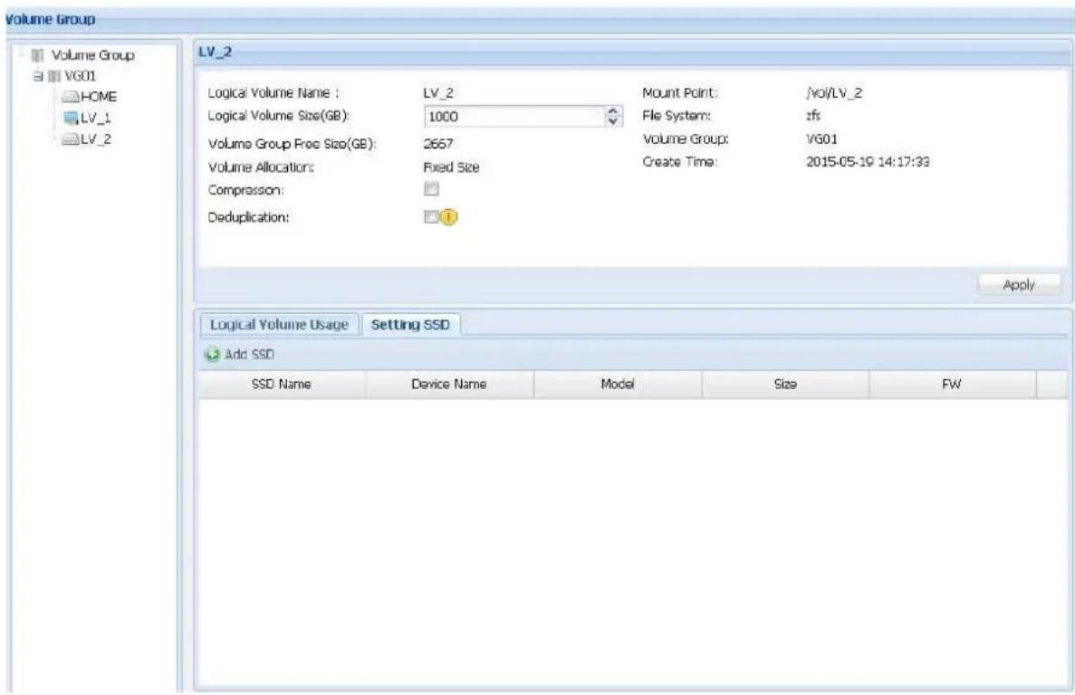
Figure 3.5.2-13 Enable SSD Caching
3.5.3 iSCSI Manager
The iSCSI Manager allows administrator of the NAS system to setup logical volumes as iSCSI Target Volumes. A logical volume that is not yet formatted or has no existing share folder in it can be setup as an iSCSI volume device.
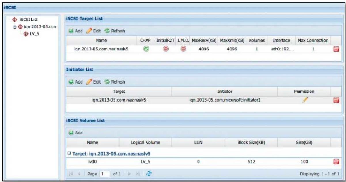
Figure 3.5.3-1 The iSCSI Manager
Add iSCSI Target: To add an iSCSI target, click 'Add' icon in the iSCSI Target List shown in Figure 3.5.3-1. The iSCSI Target setup will appear (Figure 3.5.3-2).
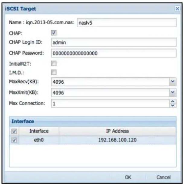
Figure 3.5.3-2 Create iSCSI Target
Name: Input iSCSI Target name
CHAP: If CHAP authentication is needed, select the 'CHAP:' option to enable it, and then input the CHAP Login ID and CHAP Password.
InitialR2T: Initial Ready to Transfer. Default is disabled. If needed to enable this option, please select it.
I.M.D.: Immediate Data. Default is disabled. If needed to enable this option, please select it.
MaxRecv(KB): Maximum data per PDU (Protocol Data Unit) to receive. Default value is 4096 KB. If needed to change the value, please modify it.
MaxXmit(KB): Maximum data per PDU (Protocol Data Unit) to transmit. Default value is 4096 KB. If needed to change the value, please modify it.
Max Connection: Default value is 1. If needed to increase the maximum number of initiator connections, please modify the value.
For example: If four initiator connections are allowed on the iSCSI target, set the 'Max Connection' value to 4.
Interface: Specify the network port dedicated for iSCSI connection. iSCSI initiators can only connect to the iSCSI target via this port.

NOTE:
The Name only allows up to 32 characters, and can only contain letters, numbers, hyphen (-) and underscore (_).
Delete iSCSI Target: To delete an iSCSI Target, select the 'Remove' icon on the right side of the iSCSI target name to be deleted. The Confirmation window will appear. Select the "Confirm:" option and click 'Yes'. The iSCSI Target will be deleted.
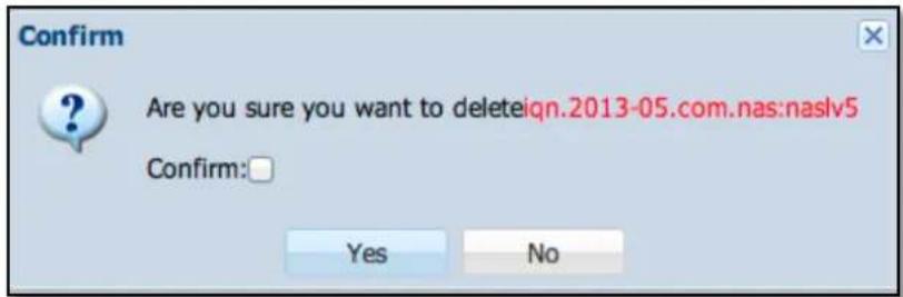
Figure 3.5.3-3 Confirm Message to Delete iSCSI Target
Add iSCSI Target Volume: Click 'Add' icon on the iSCSI Volume List. The Add iSCSI Volume window will appear.
Select a Target name, and choose the logical volume to be used as iSCSI volume, set the Size(GB), and select the Block Size(KB). After completing the setup, click 'OK'. The new iSCSI Target Volume will be created.
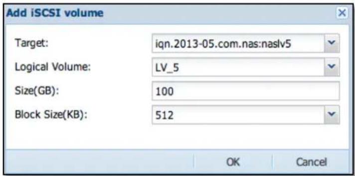
Figure 3.5.3-4 Assign a Volume to the iSCSI Target
Block Size: The default setting is 512. There are four options: 512, 1024, 2048, and 4096

NOTE: The Thin Provision volume does not support Windows full format; user can only use the quick format.
Delete iSCSI Target Volume: Click the 'Remove iSCSI Logic Volume' icon 📋 on the right of the iSCSI target volume to be deleted. The confirmation window will appear. Check the "Confirm:" option and click 'Yes'. The iSCSI Target Volume will be deleted.
Add Initiator: Click the 'Add' icon under the Initiator List. The Add Initiator window will appear. Select a Target name, enter the Initiator iqn name, and set the Permission. Click 'OK' when done.
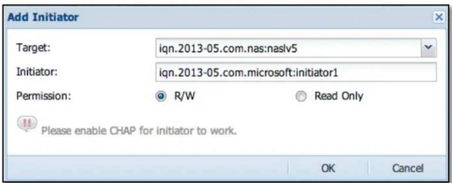
Figure 3.5.3-5 Add Initiator

NOTE: The Initiator Name only allows up to 64 characters, and can only contain letters, numbers, hyphen (-) and underscore (_).

Figure 3.5.3-6 Initiator List
Edit Initiator: To edit the Initiator permission, select from the Initiator List the Initiator name and click "Edit", or double click the Initiator name or its Permission. The following screen will appear. Only the Permission setting can be modified.
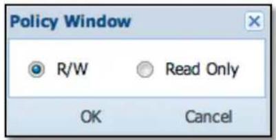
Figure 3.5.3-7 Edit Initiator Permission
Permission: Default is read/write. There are two options available: "R/W" (read/write) and "Read Only".
After modification is completed, click 'OK' button to apply the setting. If you want to undo changes, click the 'Cancel' button.
Remove Initiator: In the Initiator List, click the 'Remove' icon 📋 on the right side of the Initiator name. The Confirm window will appear. Select the "Confirm:" option and click 'Yes'. The Initiator name will be deleted.
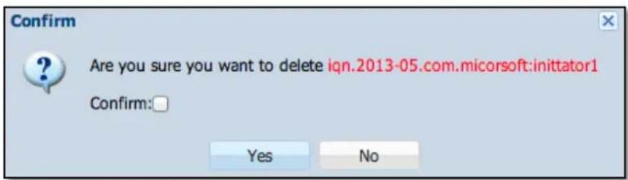
Figure 3.5.3-8 Confirm Message to Delete an Initiator
3.5.4 FC Manager
The FC Manager allows administrator of the NAS system to setup logical volumes as Target Volumes for use in Fibre SAN environment, allowing administrators to directly integrate with existing Fibre SAN environment and enable direct access to the NAS data.
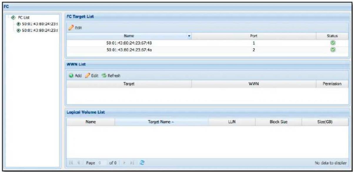
Figure 3.5.4-1 FC List
Enable or Disable FC Target Port:
Default setting of FC Target Port is Active. If needed to disable an FC Target Port, select the FC Target Name from the FC Target List and click 'Edit'. The Edit FC Target window will appear. Select the Stop option and click 'OK'. The selected FC Target Port will be disabled.
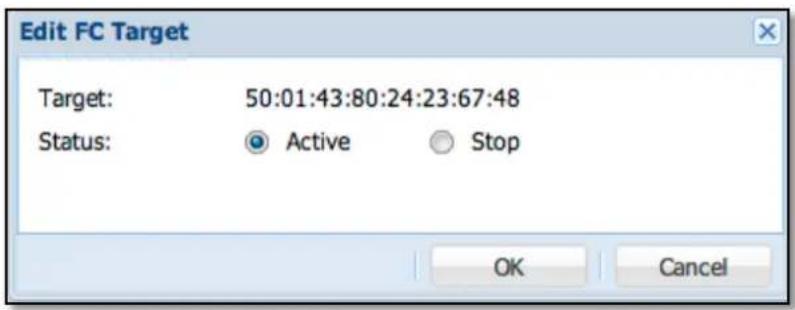
Figure 3.5.4-2 Active FC Target
Add FC Volume:
Click 'Add' in the Logic Volume List. The Add FC Volume window will appear (Figure 3.5.4-3). Select the corresponding FC Target WWN, select a logical volume and choose the Block Size. When done, click 'OK'. The settings will be immediately applied. When setup is complete, the FC Volume can be accessed via the FC Target Port, which can be connected directly to a server's FC HBA or to an FC SAN Switch.
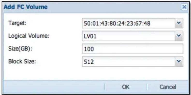
Figure 3.5.4-3 Add FC Volume
Block Size:
The default setting is 512. There are four options: 512, 1024, 2048, and 4096

NOTE: The Thin Provisioning volume does not support Windows full format; user can only use the quick format.
Add FC WWN Initiator:
This function allows admin to assign WWN initiator and permission. Click 'Add' in the WWN List. The Add WWN window will appear. Input the WWN initiator in the field.
Permission:
Default is read/write. There are two options available: "R/W" (read/write) and "Read Only".
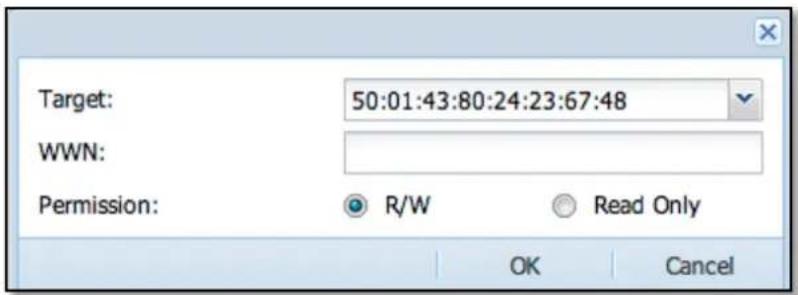
Figure 3.5.4-4 Add FC WWN Initiator
When done, click 'OK' button to apply the setting. To undo changes, click the 'Cancel' button.
Remove WWN Initiator:
In the WWN List, click the 'Remove' icon 📋 on the right side of the WWN initiator name. The Confirm window will appear. Select the "Confirm:" option and click 'Yes'. The WWN initiator name will be deleted.
Remove FC Target Volume:
Click the FC Target and find the volume in the Logical Volume List. Click the remove icon 📋 on the right side of the Logical Volume List (Figure 3.5.4-5). The confirmation window will appear. Check the "Confirm" option and click 'Yes'. The FC Volume will be removed from the target.
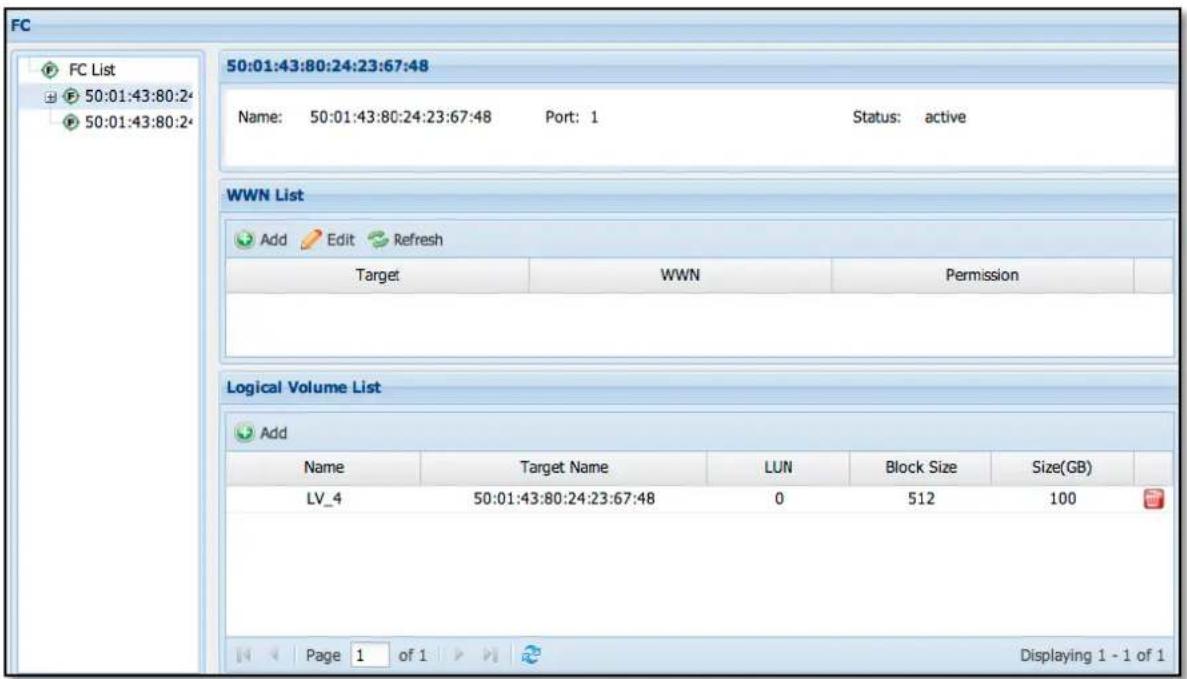
Figure 3.5.4-5 FC Target Volume Information
3.5.5 Share Manager
Share Manager allows admin to manage share folders that can be accessed by users via Samba (SMB/CIFS), NFS, AFP, FTP, WebDAV, and Rsync.
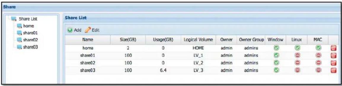
Figure 3.5.5-1 Share List
Add Share: In the Share List, click 'Add'. The Add Share window will appear. Follow the setup instructions step by step. After setup in one page, click 'Next' to go to next setup page until completed and share folder is created.
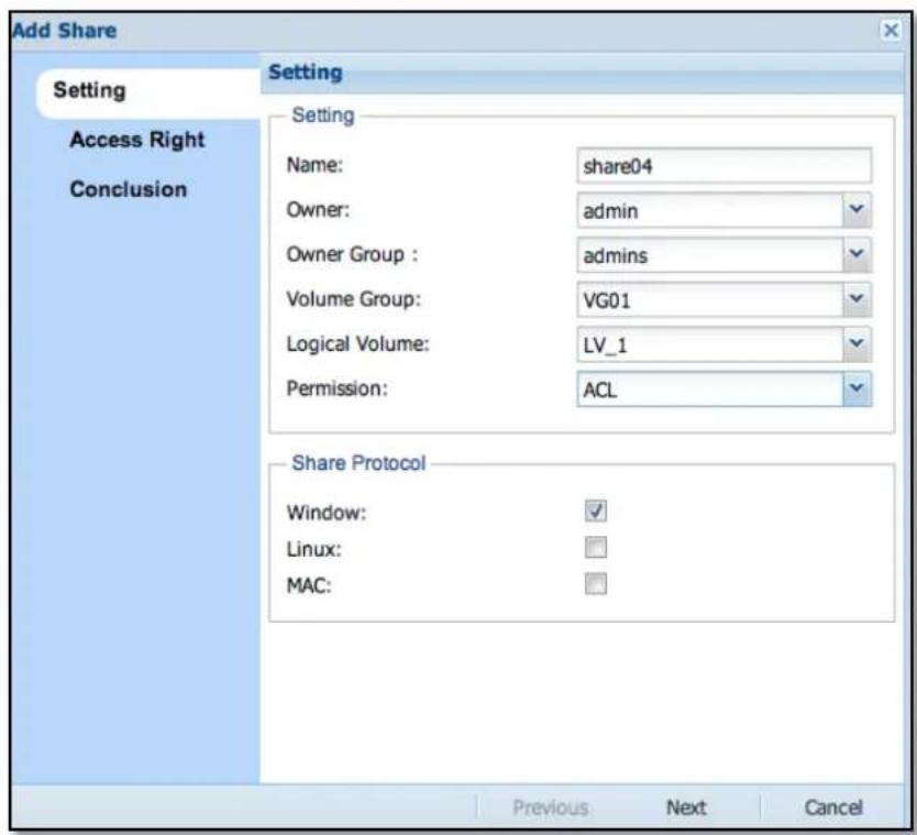
Figure 3.5.5-2 Create a New Share
Name: Enter name of the share folder. The Name can be up to 32 characters, and can only contain letters, numbers, hyphen (-) or underscore (_).
Owner: Default share folder owner is admin. If needed to change the owner, select other user account.
Volume Group: Select the volume group where the share folder will be created.
Logical Volume: Select the logical volume where the share folder will be created, or create a new logical volume by selecting "Create New".
New Share Size (GB): This option appears only when "Create New" is selected in Logical Volume. Enter the size for the new volume to be created.
Volume Group Free size (GB): This option appears only when "Create New" is selected in Logical Volume. This is the available capacity of the selected Volume Group. This information is for reference only and cannot be modified.
Permission: Default is ACL. There are three options available: ACL, No ACL, and Public.
Share Protocol: Default option selected is Windows. There are three options available: Windows (Samba), Linux (NFS), and MAC (AFP).
When setup is completed, click 'Next' to go to the Access Right configuration page. See Figure 3.5.5-3.
Figure 3.5.5-3 Set Access Right for the New Share
Add Account Permission:
In Access Right page, click 'Account' button. The Account List window (Figure 3.5.5-5) will appear. Select the name of the account that will be assigned access permission to the share folder and click 'OK'. The account name will appear in Access Right list with read/write (R/W) permission (Figure 3.5.5-3). If the access permission of the account needs to be modified, click the 'Edit' button (pencil icon) on the right side of 'Policy' column. The option to modify access permission will be shown (Figure 3.5.5-5). There are 2 options: "R/W" (read/write) and "Read Only". Set the preferred access mode and click 'OK' when done.
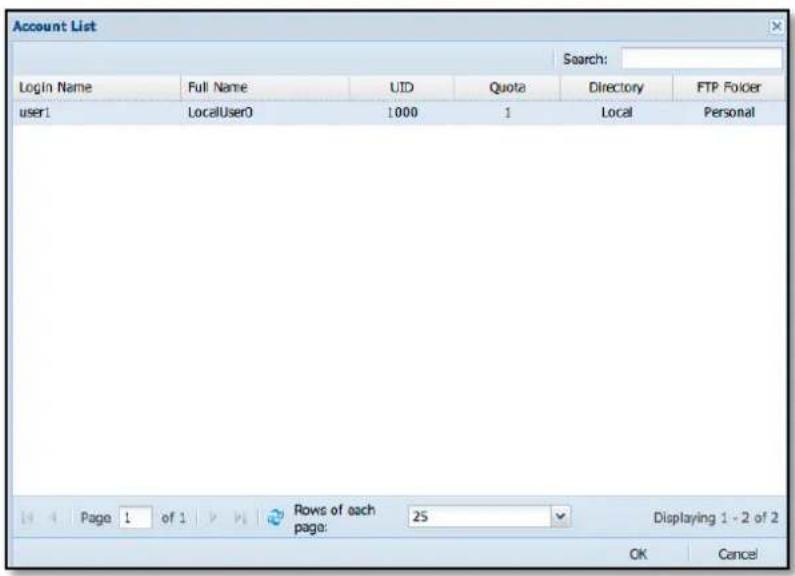
Figure 3.5.5-4 Select Accounts for Setting Share Permission
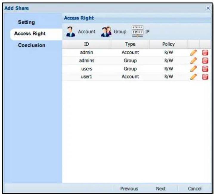
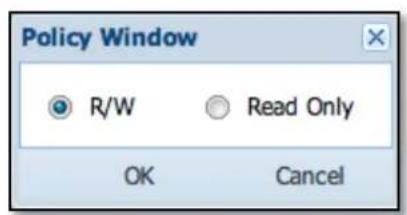
Figure 3.5.5-5 Modify Account Policy in the Share
Add Group Permission:
By default, all accounts in the 'users' group are allowed access to the share folders. If you need to assign permission to another group, click 'Group' button. The Group List window (Figure 3.5.5-6) will appear. Select the name of the Group that will be assigned permission to the share folder and click 'OK'. The group name will appear in the Access Right list with read/write (R/W) permission. If the access permission of the group needs to be modified, click the 'Edit' button (pencil icon) on the right side of 'Policy' column. The option to modify access permission will be shown (Figure 3.5.5-7). There are 2 options: "R/W" (read/write) and "Read Only". Set the preferred access mode and click 'OK' when done.
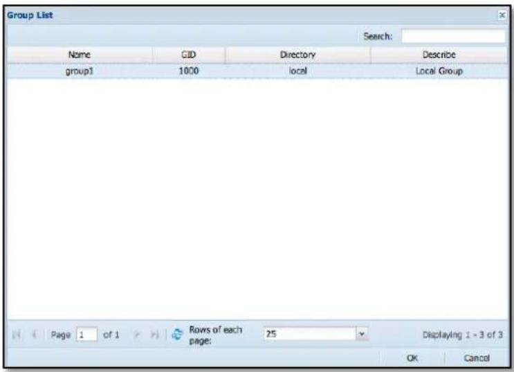
Figure 3.5.5-6 Select Groups for Setting Share Permission
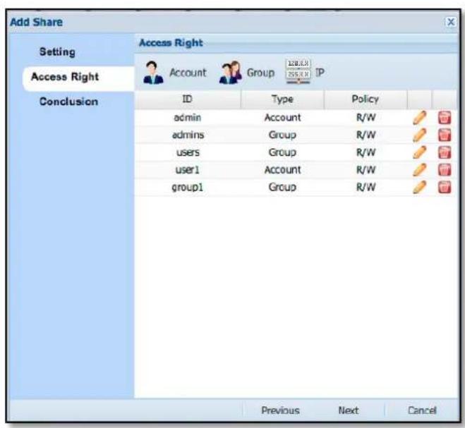
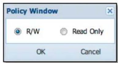
Figure 3.5.5-7 Modify Group Policy in the Share
Add IP Permission:
By default, all client IP addresses are allowed access to the share folders. If you need to assign specific client IP, click the 'IP' button. The Client IP window will appear (Figure 3.5.5-8). Enter the client IP address that will be allowed access to the share folder. Set the Permission, whether "R/W" (read/write) or "Read Only (NFS Only)". Click 'OK' when done. The IP address will appear in the Access Right list (Figure 3.5.5-9). If the access permission of the IP address needs to be modified, click the 'Edit' button (pencil icon) on the right side of 'Policy' column. The option to modify access permission will be shown (Figure 3.5.5-8). Set the preferred access mode and click 'OK' when done.

Figure 3.5.5-8 Add Client IP in the Access Right List
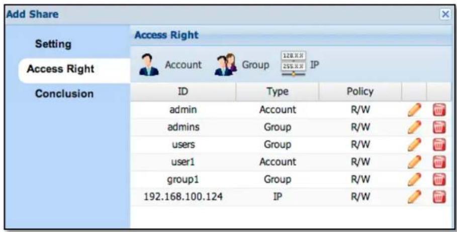
Figure 3.5.5-9 Client IP in Access Right List
When Access Right configuration is completed, click 'Next' for confirming the settings. Verify the share folder configuration in the Conclusion page (Figure 3.5.5-10) and make sure all settings correct. Click 'OK' to save all settings.
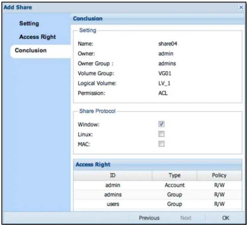
Figure 3.5.5-10 Conclusion Page Before Creating Share
Edit Share Folder:
Please select the share folder name to be edited from the Share List (Figure 3.5.5-11), and then click 'Edit' icon, the Share Information now can be modified (Figure 3.5.5-12)
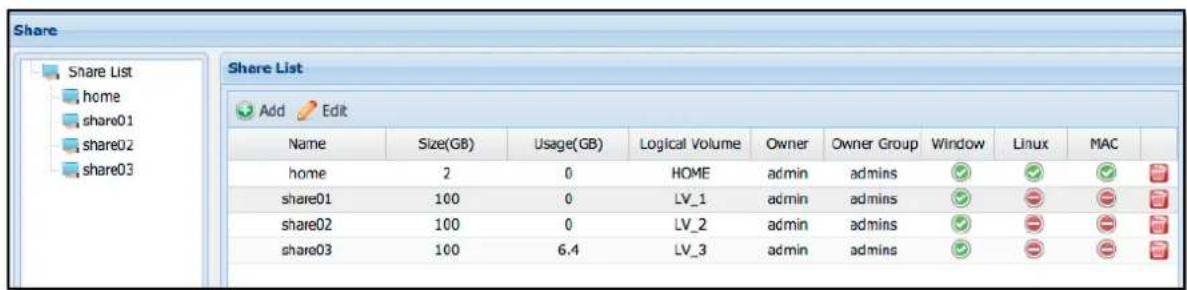
Figure 3.5.5-11 Share List
Name : The share name is fixed and cannot be edited.
Logical Volume: Shows the Logical Volume name where the share was created from.
Size: The capacity of Logical Volume.
Owner: The share owner, and who always has write permission.
Owner Group: The default group owner of share, and who always has write permission.
Permission: You can set the share access control with or without ACL. If "NoACL" is selected, you can specify the share directory mode as commonly used in Linux systems, like "755", or choose "Public" to allow users access to this share (which also means NoACL mode as "777").
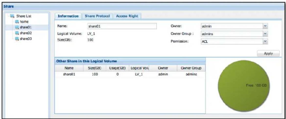
Figure 3.5.5-12 Share Information
Share Protocol:
As shown in Figure 3.5.5-13, there are 4 Share Protocol options that can be enabled: CIFS (Samba), NFS, Apple Talk (AFP) and Rsync.
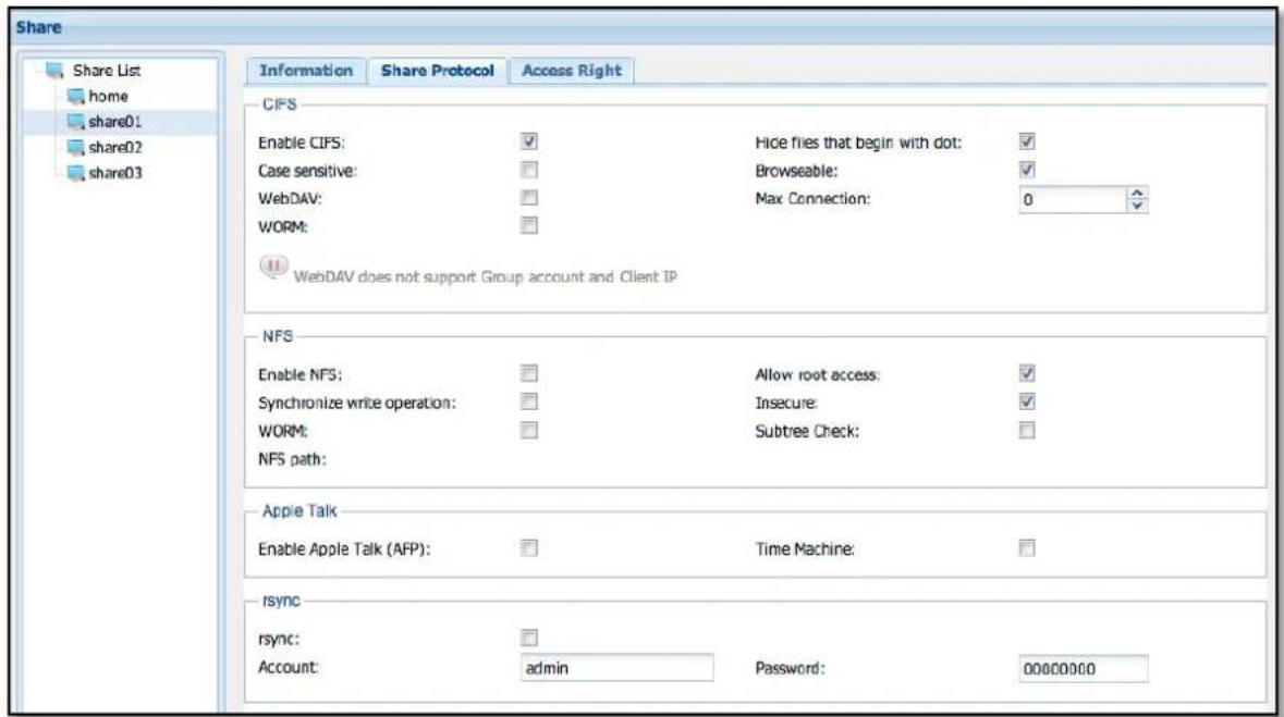
Figure 3.5.5-13 Share Protocol
CIFS
Enable CIFS: Enable and export share for CIFS (Windows) clients.
Case sensitive: Controls whether filenames are case sensitive or not.
WebDAV: When enabled, WebDAV clients are allowed access to the share.
WORM: Write Once Read Many. When this is enabled, all users with permission can only create files but cannot modify or delete it. Only the share owner can delete or modify newly created files.
Hide files that begin with dot: Hide the files that name begin with dot.
Browseable: This option controls whether the share folder will be visible and can be browsed when client PC connects to the NAS. Default setting is enabled. When disabled, and client PC connect to the NAS via CIFS, the share folder will not be visible.
MaxConnection: Set the maximum number of client connection. "0" means no limit.
NFS
Enable NFS: Enable and export share for NFS clients
Allow root access: When this option is enabled, root access to share is allowed.
Synchronize write operation: This option is used to set share IO with synchronous write.
WORM: Write Once Read Many. When this is enabled, all users with permission can only create files but cannot modify or delete it. Only the share owner can delete or modify newly created files.
Insecure: Allows request from IP port larger than 1024.
Subtree Check: Do subtree checking while share is being accessed. Default is Disabled (no subtree checking).
Apple Talk
Enable Apple Talk(AFP): Enable and export share for Apple MAC clients
Time Machine: Enable and export share that can be discovered by "Time Machine" backup application in MAC.
Rsync
Account: Set the user name that will be used for share login via Rsync.
Password: Set the password that will be used for share login via Rsync.
Edit Access Right:
You can modify share permission in the "Access Right" tab by clicking Account/Group/IP in the list (Figure 3.5.5-14), or clicking "Account/Group/IP" at the top to assign new permission. If you want to remove the account/group/IP assigned in the share, just click 📋 at the right-most column of the ID to be removed.
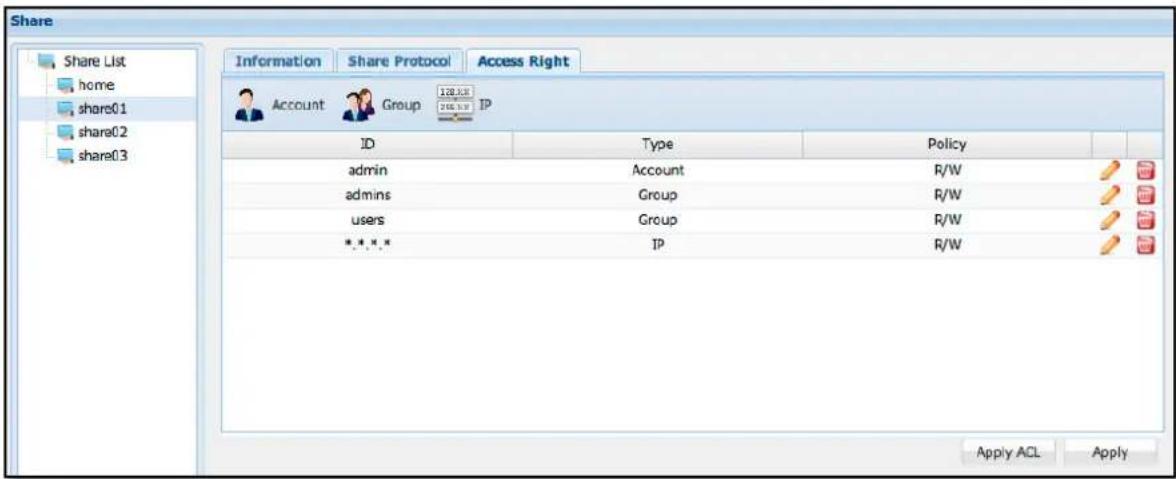
Figure 3.5.5-14 Share Access Right
Delete Share Folders:
In the Share List, click the delete icon (Figure 3.5.5-15) on the right of the Share Folder name to be deleted. The Confirmation window (Figure 3.5.5-16) will be displayed. Select the "Confirm:" option and click 'Yes' to continue deleting the selected share folder.
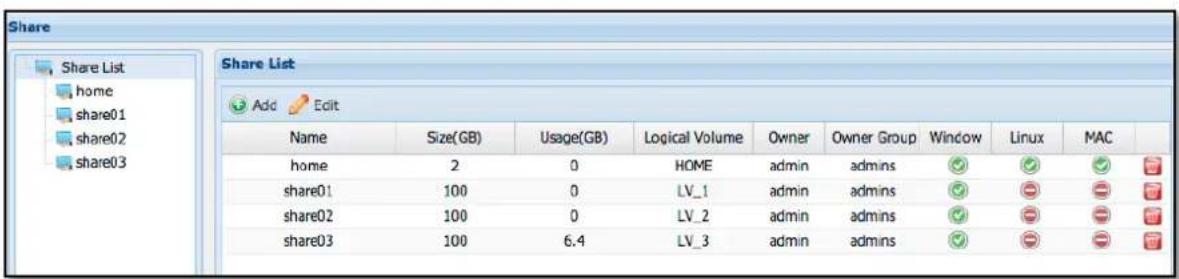
Figure 3.5.5-15 Share list
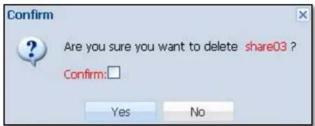
Figure 3.5.5-16 Confirm Message to Delete Share
3.6 Service Manger

3.6.1 Samba service
Samba provides SMB/CIFS file and printer sharing. This service needs to be enabled so that MS Windows systems can access NAS share folders or printer.
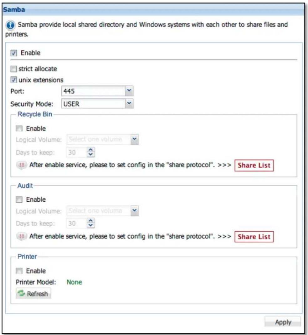
Figure 3.6.1-1 Samba Options
Enable: To start Samba service, select the 'Enable' option. To stop this service, unselect this option. Modify other options if necessary. Click 'Apply' when done,
Strict allocate: This option controls the handling of logical volume space allocation. When disabled (default setting is disabled or un-checked), the system does not sparse logical volume block allocation when a file is extended. To enable this option, select it and click 'Apply'.
Unix extensions: Default is enabled. To disable this option, deselect (uncheck) it and click 'Apply'.
Port: Default is 445. There are 3 options: 445, 139, and '445,139'
Security Mode: Default is set to USER. There are two options available for setup: USER, SHARE
Recycle Bin: This option allows deleted files from the NAS share folder to be retained in the Recycle Bin share folder.
To enable Recycle Bin, select the 'Enable' option, and then select the logical volume that will be used to store the Recycle Bin data. Setup the 'Days to keep:' option for the number of days you want to keep the deleted files in the Recycle Bin. Click 'Apply' when setup is done. The Recycle Bin function will be enabled.
Audit: This option provides record of all user access to share folder data. Some examples of information are add/delete/modify record.
To enable Audit, select the 'Enable' option, and then select the logical volume that will be used to store the Audit information. Setup the 'days to keep:' option for the number of days to retain Audit information. Click 'Apply' when setup is done. The Audit function will be enabled.
Printer: Enable this option to connect and detect a USB printer and share it to clients.

NOTE: For detailed options, please edit Share Protocol in Share manager.
3.6.2 NFS service
NFS provides Network File System file sharing. This service must be enabled so that UNIX and Linux systems will be able to access (mount) the NAS share folders.
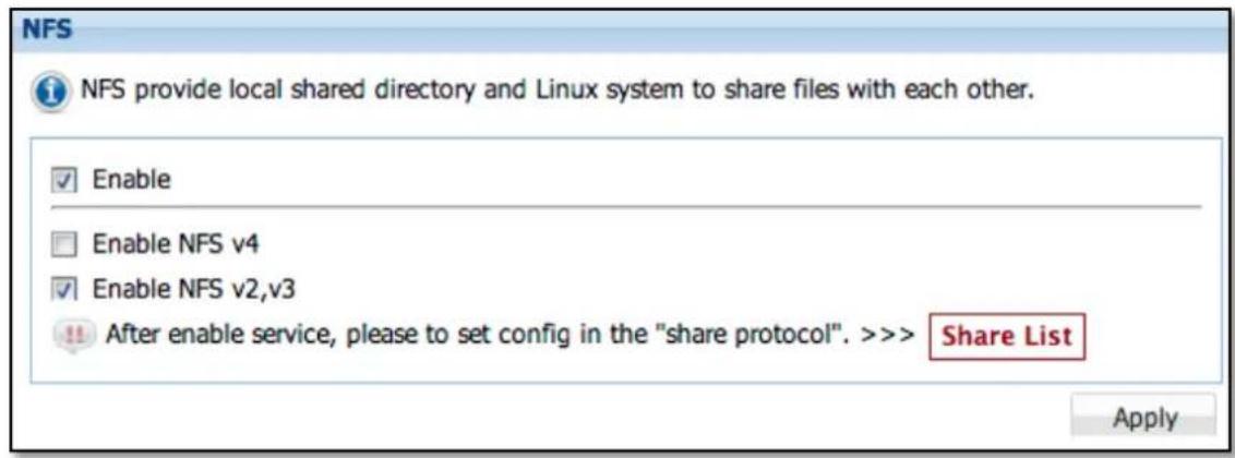
Figure 3.6.2-1 NFS Options
Enable: To start NFS service, select the 'Enable' option, or unselect this option to stop service, Choose the NFS version option if needed. Click 'Apply' when done.
Enable NFSv4: Default is disabled. To enable support for NFS version 4, select this option.
Enable NFS v2, v3: Default is enabled, which means NFS version 2 and version 3 are supported. To disable this option, deselect it (check mark will disappear).

NOTE: The detailed options please edit Share Protocol in Share manager.
3.6.3 AFP service
AFP provides file services for Mac OS X and original Mac OS. This service need to be enabled so that Mac OS users will be able to access the NAS share folders vi AFP.
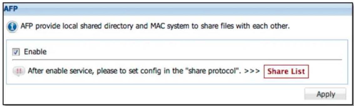
Figure 3.6.3-1 AFP Options
Enable: To start AFP service, select the 'Enable' option and the click 'Apply'. To stop this service, unselect option and clicn 'Apply'.

NOTE: The detailed options please edit Share Protocol in Share manager.
3.6.4 FTP service
FTP is a standard network protocol used to transfer files to/from NASfrom/ to another host over a TCP-based network After this service is enabled, NAS accounts can be used to login NAS and access share folders via FTP.
Enable: To start FTP service, select the 'Enable' option. If necessary, modify the Port and Max Connections options. Click 'Apply' when done. To stop this service, unselect this option and click 'Apply'.
Port: Default port used by FTP is 21. If modified, select from range 1024 to 65534.
Max connections: Default maximum number of FTP connections is 10. If modified, number can be changed up to 1000.
Type: Select option: FTP (general support only), FTP over explicit TLS/SSL, or Both
SFTP: Select to enable SFTP (Secure FTP), please note that SSH service will also enabled when SFTP selected.
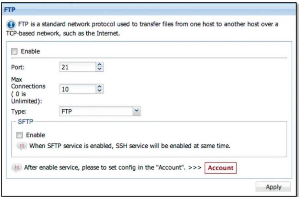
Figure 3.6.4-1 FTP Options
3.6.5 WebDAV service
WebDAV protocol makes the Web a readable and writable medium. It provides a framework for users to create, change and move documents on a server; typically a web server or web share.
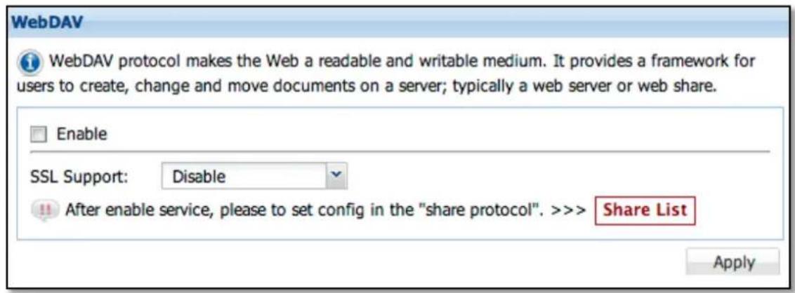
Figure 3.6.5-1 WebDAV Options
Enable : Select and click 'Apply' to start WebDAV service. To stop service, unselect this option and click "Apply".
SSL Support : Disable or enable HTTPS support.
3.6.6 TFTP service
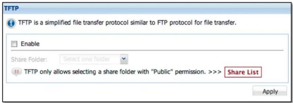
Figure 3.6.6-1 TFTP Options
Enable: To start TFTP service, select the 'Enable' option and then choose a share folder (must be a share folder set as "Public"). Click 'Apply' when done. To stop service, unselect this option and click 'Apply'.
3.6.7 Rsync service
Rsync is a file transfer program which provides copying and udpating files to/from NAS share foler from/to a remote Rsync host, such as another NAS.
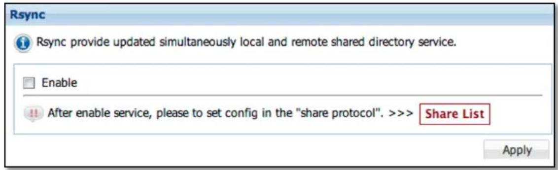
Figure 3.6.7-1 Rsync Options
Enable: To start Rsync service, select the 'Enable' option and click 'Apply. To stop service, unselect this option and click 'Apply'.
Bonjour provides a general method to discover services in the LAN. It is designed to help devices and applications discover each other on the same network.
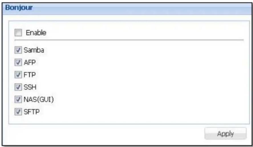
Figure 3.6.8-1 Bonjour Options
Enable: To start Bonjour service, select the 'Enable' option and click 'Apply'. To stop sevice, unselect this option and click 'Apply'.
3.6.9 SNMP service
SNMP is used mostly in network management systems to monitor network-attached devices for conditions that warrant administrative attention.
Start SNMP Service: To enable SNMP service, select the 'Enable' option. Choose the SNMP version if necessary. By default, SNMP version 1 and 2 is enabled. Click 'Apply' when done.
Enable SNMP v3: To enable support for SNMP version 3, select the 'Enable snmp v3' option, then setup Auth Protocol, Auth Password, Priv Protocol, and Priv Password. Click 'Apply' when done.
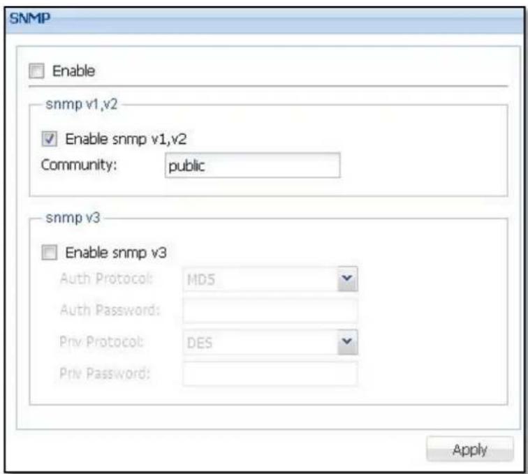
Figure 3.6.9-1 SNMP Options
3.6.10 DHCP service
DHCP service enables the NAS to function as DHCP server and provides automatically assigned IP address to other computers in the internal network or LAN.
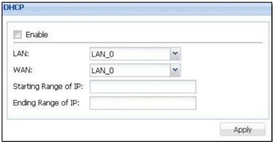
Figure 3.6.10-1 DHCP Options
Enable: To start DHCP service, select the 'Enable' option. Modify the other settings as necessary. Click 'Apply' when done. The DHCP service will be started and the NAS system will act as DHCP server, providing dynamic IP addresses to client PCs. To stop service, unselect this option and click 'Apply'.
LAN: Select the LAN interface that is connected to private/internal network, the same network segment as the client PCs.
WAN: Select the LAN interface that is connected to public/external network, the same network segment that has internet/WAN connection.
Start Range of IP: Enter the starting IP address of the range of addresses (dynamic IP) for the private/internal network.
Ending Range of IP: Enter the ending IP address of the range of addresses (dynamic IP) for the internal network.
3.6.11 SSH service
SSH (Secure Shell) is a network protocol that allows data to be exchanged using an encrypted and secure channel between the NAS and a remote host.
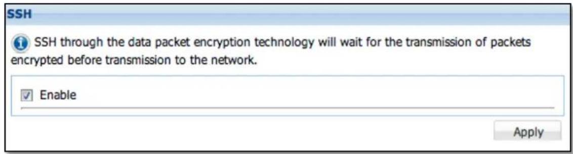
Figure 3.6.11-1 SSH Options
Enable: To start SSH service, select the 'Enable' option and click 'Apply'. To stop service, unselect this option and click 'Apply'.
3.6.12 Telnet service
Telnet is a network protocol used on the Internet or local area networks to provide a bidirectional interactive text-oriented communication facility using a virtual terminal connection.
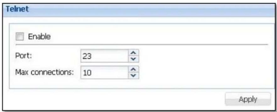
Figure 3.6.12-1 Telnet Options
Enable: To start Telnet service, select the 'Enable' option. If necessary, modify the Port and Max Connections options. Click 'Apply' when done. To stop service, unselect this option and click 'Apply'.
Port: Default port used by Telnet is 23. If modified, select from range 1024 to 65534.
Max connections: Default maximum number of Telnet connections is 10. If modified, number can be up to 1000.
3.6.13 File Manager
File Manager provide NAS user accounts access to NAS share folders and files via web GUI.
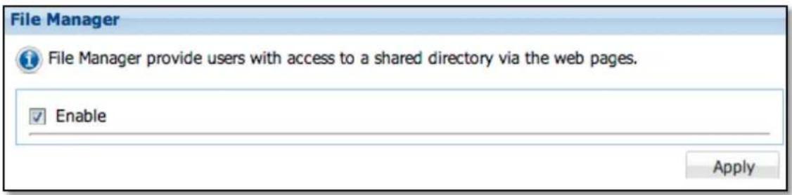
Figure 3.6.13-1 File Manager Options
Enable: To start File Manager service, select the 'Enable' option and click 'Apply'. To stop service, unselect this option and click 'Apply'.
More information about File Manager please see Chapter 3.11.
3.7 Account Manager
3.7.1 Account

Figure 3.7.1-1 Account List
Add Account: To add a new account, click 'Add' button in Account Manager. The 'Add new account' window will appear. Follow the 'Add new account' setup wizard (Figure 3.7.1-2).
Account Setting: Enter the account information such as Login Name, Full Name, Password, and other necessary settings. When done, click 'Next' to go the next setup page 'Assign Share'.
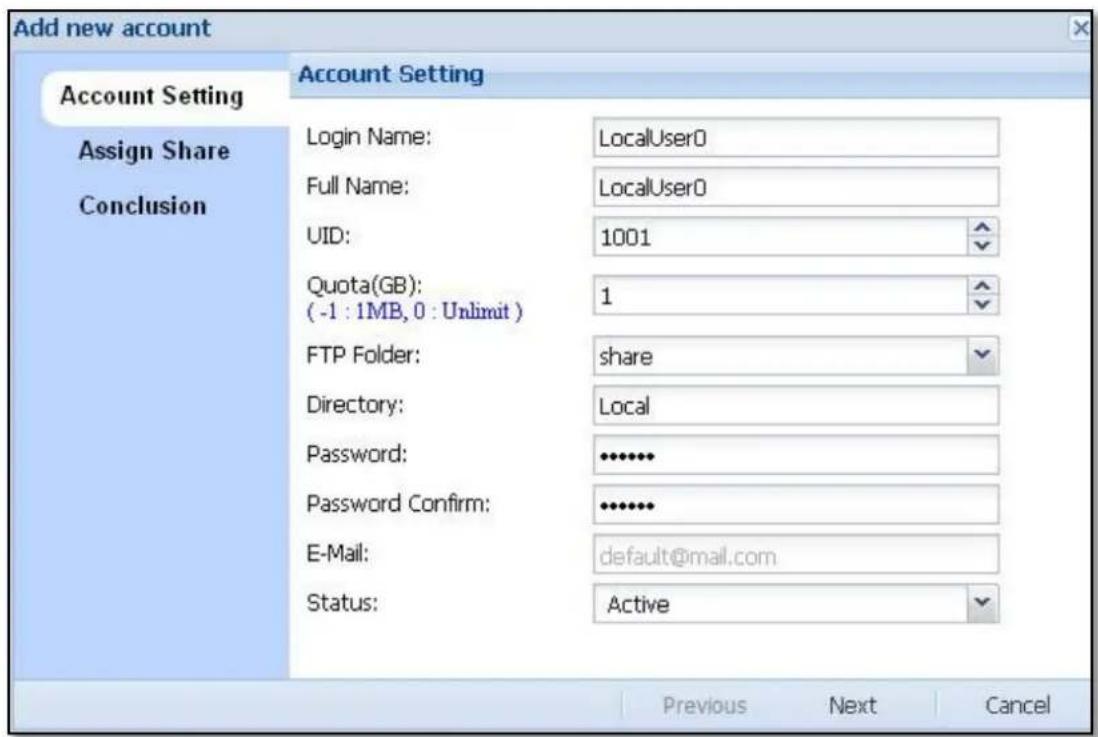
Figure 3.7.1-2 Add New Account Setting
Login Name: Please enter the account name. Account name allows up to 32 characters and can only contain letters, numbers, hyphen (-), and underscore (_). A space or period (.) is not allowed.
Fully Name: Enter a full name or a descriptive name for the account.
Quota (GB): Set the quota/limitation for the account's personal (home) folder. To disable (turn off) the quota for the account's personal folder, set the value to "-1". To set the quota to no limit, set the value to "0".
FTP Folder: Select the default FTP folder for the account. This option will direct the user account to the selected share folder, when user account login via FTP. Options include all existing share folders, Personal, and All.
Directory: This information is set by the system automatically. When an account is created in the NAS system, this field will show 'Local'.
Password: Enter password for the account. Password can contain at least 6 characters, can be up to 32 characters, and can only contain letters, numbers and special characters _ - \~! @ # \$% ^ & *. The following characters cannot be used [] {} ().
Password Confirm: Enter the same password again.
E-mail: Enter e-mail address for this account.
Status: Default is 'Active' or enabled. If administrator wants to disable this account, set this to 'Inactive'.
Assign Share: Select the share folders that this account can access, and click 'Next' to go to the next page "Conclusion".
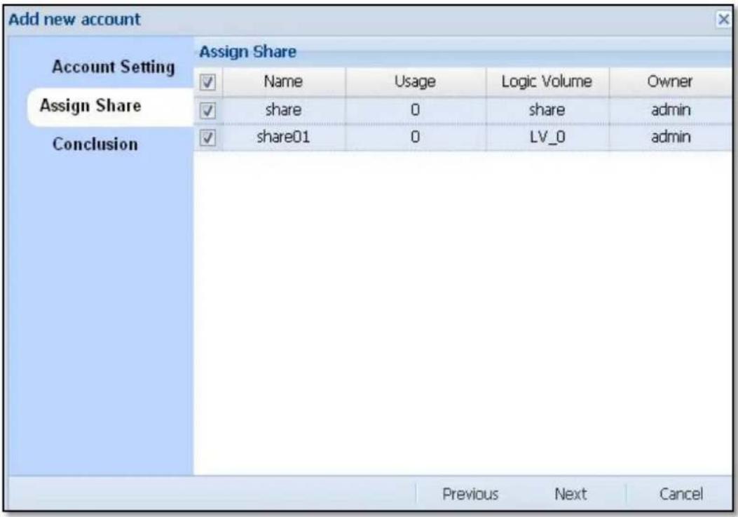
Figure 3.7.1-3 Add New Account, Assign Share Setting
Conclusion: Verify that the account settings are correct. Click 'OK' when done. The new account will be created.
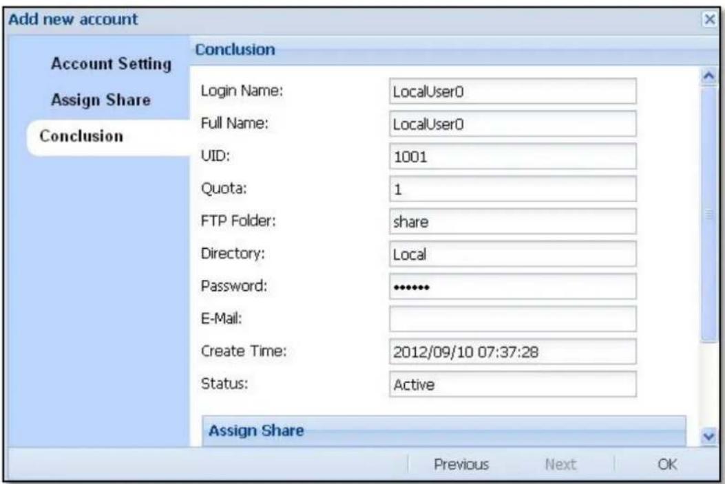
Figure 3.7.1-4 Confirm Information to Create a New Account
Edit: To edit an account, select the account name in the Account Manager's list, and click 'Edit'. The Account Setting page will appear. Modify the settings if necessary. Click 'Next'.
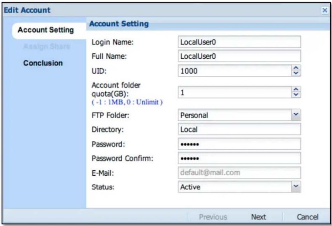
Figure 3.7.1-5 Edit Account
The step to modify account is just like the step to create account, but some options like Login Name, Full Name and UID are disabled and cannot be modified.
Conclusion: Verify that the account settings are correct. Click 'OK' when done. The system will update the new settings for the account.
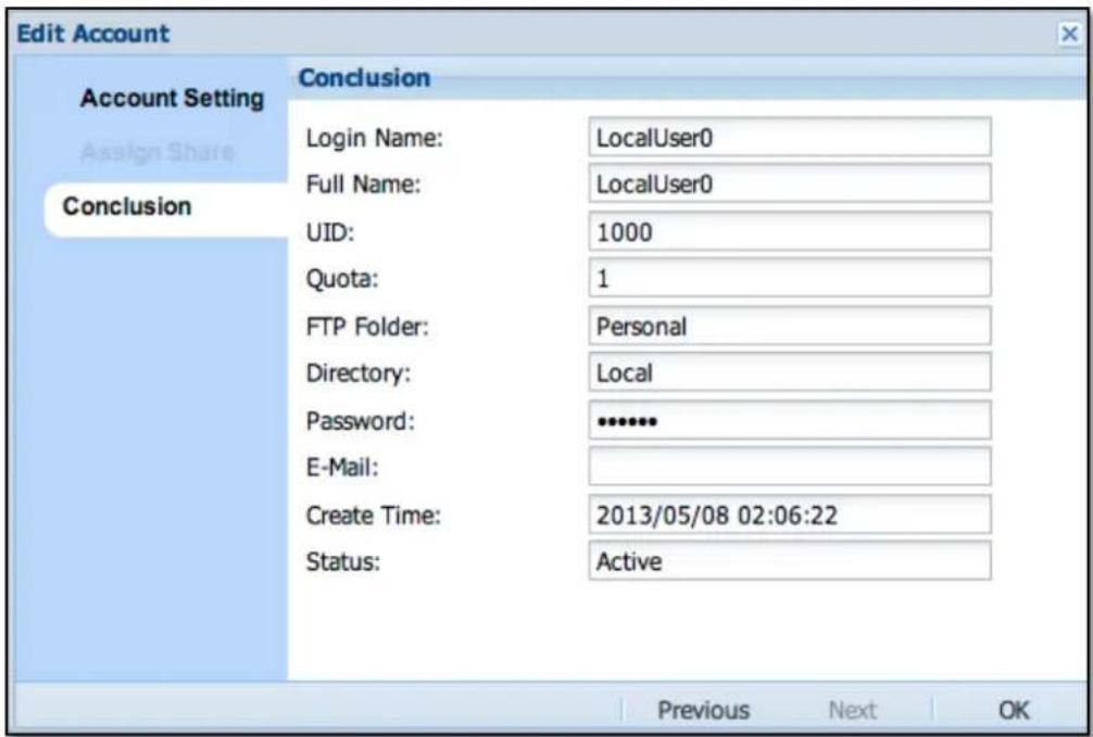
Figure 3.7.1-6 Confirm Information to Edit Account
Delete Account: Click the delete icon 📋 on the right of the account name to be deleted (Figure 3.7.1-7). The confirmation window will be displayed. Select the "Confirm:" option and click 'Yes' (Figure 3.7.1-8). The account name will be deleted.

Figure 3.7.1-7 Account Manager, Account List
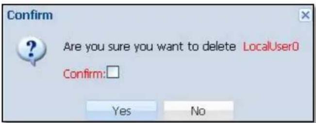
Figure 3.7.1-8 Confirm Information to Delete Account
Import Account: In Account Manager (figure 3.7.1-7), click the 'Import Account' button. The Import Account window will appear. Click the
'select file' icon , and select the file (extension must be CSV) containing the account list that will be imported to the NAS system. Click 'OK' when done. The accounts will be automatically added to the Account list.
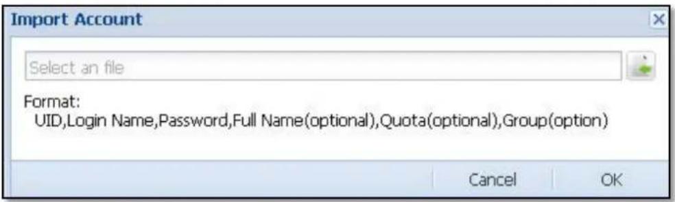
Figure 3.7.1-9 Import Acount
Format of each Account Entry:
UID, Login Name, Password, Full Name, Quota, Group Name

NOTE: Each field in an account entry must be separated by comma, and there should be no space between commas. In the CSV file, each account entry must be in one line.
For example:
1001, Tony, 1qazxsw2, Tony Lee, 10, Sales
1002, Scott, qwerty123, PM Scott, 10, PM
Export Account: Click the 'Export Account' button. Save the account file (default file name is "nasaccount.csv") to your client computer. The account file can be used later for account recovery/import.
3.7.2 Group

Figure 3.7.2-1 Group Manager, Group list
Add New Group: Click 'Add' button. The Add Group window will appear. Setup the Group Setting.
Name: Enter the name for the local group. The group name allows up to 32 characters and can only contain letters, numbers, hyphen (-), and underscore (_). A space or period (.) is not allowed.
GID: System default value starts with 1000. If needed to assign other GID (group ID), select the preferred GID using the arrow-down or arrow-up button. Duplicate GID is not allowed.
Describe: Enter a description for the new local group.
Add Account to Group: Select the account name that you want to join to the group by using the mouse and dragging the account name from Account List into the Group Member pane. When done, click 'Next' to go to Conclusion page.
Remove Account from Group: In Group Member list, select account name you want to remove the group, and use the mouse to drag the account from the Group Member pane to the Account List pane on the left side. When done, click 'Next' to go to Conclusion page.
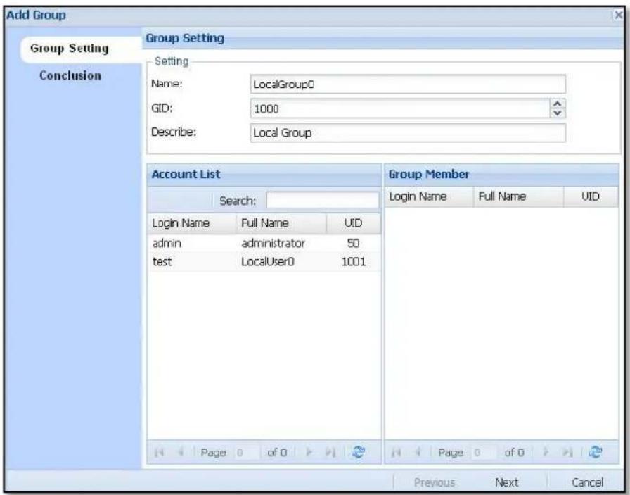
Figure 3.7.2-2 Add New Group
Conclusion: Verify settings for the new group if correct. Click 'OK' when done. The new group will be created.
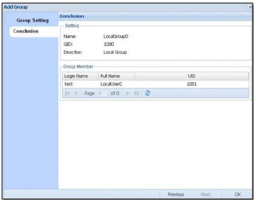
Figure 3.7.2-3 Confirm Message to Create Group
Edit Group: In the Group Manager list (Figure 3.7.2-1), click the group name to be edited and then click 'Edit' button. The following window will appear.
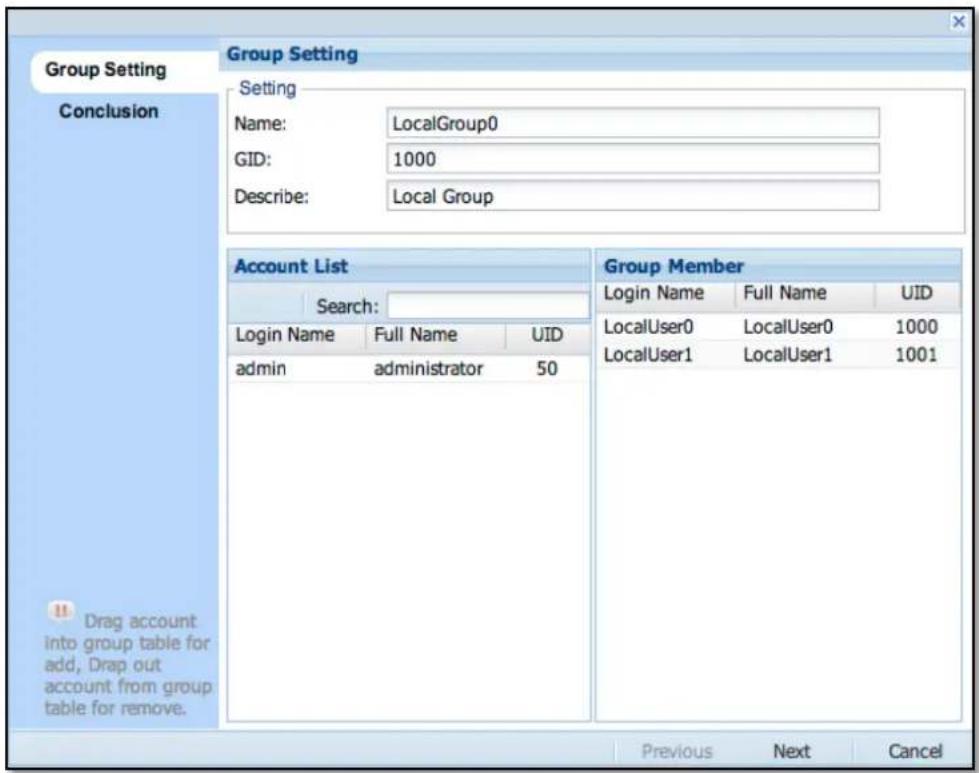
Figure 3.7.2-4 Edit Group
The step to modify group is just like the step to create group, but some options like Name and GID are disabled and cannot be modified.
Delete Group: Click the delete icon 📋 on the right side of the group name to be deleted (Figure 3.7.2-1). The confirmation window will be displayed (Figure 3.7.2-5). Select the "Confirm:" option and click 'Yes' button. The group will be deleted.
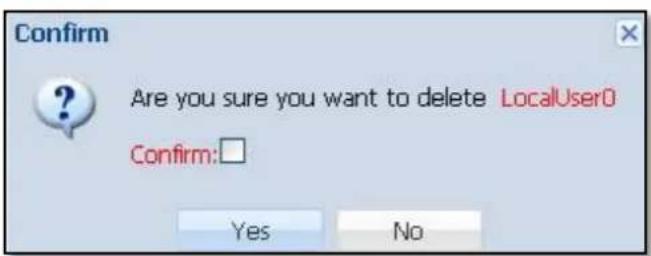
Figure 3.7.2-5 Confirm Message to delete Group
3.7.3 Directory Service
Enable ADS Authentication:
To start the Windows directory service ADS, select this option. Configure the ADS settings. When done, click 'Apply' button. The NAS system will be joined to the Windows domain, and ADS accounts and groups will be shown in the Account and Group list in the NAS system. Administrator can then assign share folder permission to these ADS accounts and groups.
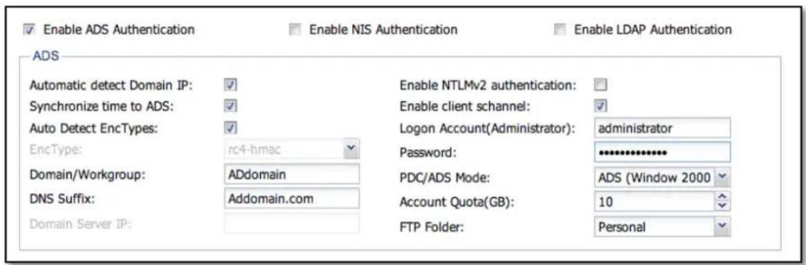
Figure 3.7.3-1 Enable ADS Authentication
Automatic detect Domain IP:
Default is enabled. To use this option, DNS must be set first in "System Manager" → "Network" → "DNS". If system does not automatically detect the domain server IP, this option can be disabled, and then the domain server IP address can be manually entered in the "Domain Server IP" box.
Synchronize time to ADS:
Default is enabled. NAS system will synchronize time from ADS domain server. If administrator wants to synchronize time from NTP Server, this option must be disabled and NTP Server must be setup in "System Manager" → "General" → "Date/Time".

NOTE: When NAS system is set to synchronize time from NTP Server, the ADS domain server must also synchronize time from the same NTP Server to avoid desynchronized time between ADS server and NAS system, which can result in failure to join the NAS to ADS domain.
Auto Detect Enctypes:
Default is enabled which means the NAS will automatically detect the encryption type. If ADS Server is using a special password encryption mode, please disable this option and select the appropriate encryption mode from "EncType" field. Click first the arrow-down button on the right to see the various encryption mode options.
Enctype: After "Automatic Detect Enctypes" is disabled, this function will be enabled.
Domain/Workgroup: Enter the domain name, for example: MYDOMAIN, or enter the workgroup name.
DNS Suffix: Enter the fully qualified domain name. For example: MYDOMAIN.COM
Doman Server IP: The "Automatic detect Domain IP" option must be disabled, and then the domain server's IP address can be manually entered here.
Enable NTLMv2 authentication: Default is disabled. To enable NTLMv2 authentication, select this option.
Enable client schannel: Default is enabled.
Logon Account (Administrator): Enter the domain administrator's account name.
Password: Enter the password for the domain administrator's account name.
PDC/ADS Mode: Select the domain server mode, ADS or PDC. ADS include Windows 2000, 2003, and 2008 Server, and PDC includes Windows NT Sever.
Account Quota (GB): Set the quota/limitation for the domain account's personal (home) folder. To disable (turn off) the quota for the domain account's personal folder, set the value to "-1". To set the quota to no limit, set the value to "0".
FTP Folder: Select the default FTP folder for the domain account. This option will direct the domain account to the selected FTP share folder, when user account login via FTP.
Enable NIS Authentication:
To start the NIS directory service, select this option and set the following information below. Click 'Apply' when done. The NIS domain accounts and groups will be added in Account and Group list, and then administrator can set share folder access permissions to the accounts or groups.
NIS Domain: Enter the NIS domain name
NIS Server: Enter NIS Server IP address.
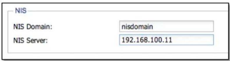
Figure 3.7.3-2 Enable NIS Authentication
Enable LDAP Authentication:
To start the LDAP directory service, select this option and set following information below. When done, click 'Apply'. The LDAP accounts and groups will be added to the Account and Group list, and then administrator can set share folder access permissions to the accounts or groups.
LDAP server DC suffix: Enter the LDAP DC suffix. For example:
dc=ldapserver, dc=com
LDAP server IP: Enter the LDAP Server IP address.
LDAP admin DN: Enter the LDAP administrator DN. For example:
cn=admin,dc=ldapserver,dc=com
LDAP admin password: Enter the LDAP administrator password.

NOTE: If administrator wants to use LDAP accounts and groups to be assigned Samba share folder access, administrator must start first in the LDAP server the Samba account schema and then start the LDAP directory services in NAS. If Samba account schema is not activated in LDAP server, the NAS system can only use LDAP server's accounts and groups to be assigned share folder access via FTP.

Figure 3.7.3-3 Enable LDAP Authentication
3.8 Backup Manager

3.8.1 Data Backup
The Data Backup pack all selected files into a single backup file, and it supports full, incremental and differential backup of specified share folder containing data, and also supports scheduled backups. Supported backup destinations are: Local Share folder in NAS, External Devices such as USB external disk, Samba (SMB/CIFS) remote share folder, and NFS remote share folder.
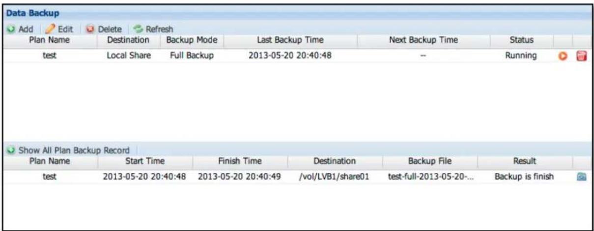
Figure 3.8.1-1 Data Backup Plan List
Add Backup Plan: Click the 'Add' icon. The Add Backup window will be displayed.
Step 1: Configure the basic settings, such as plan name, destination, and mode.
Plan Name: Enter the name of the backup plan. The plan name allows up to 32 characters, and can only contain letters, numbers, hyphen (-), and underscore (_). Space and period (.) is not allowed. Duplicate backup plan name is also not allowed.
Destination Description:
| Destination Setting Description | ||
| Local Share(Figure 3.8.1-2) | Share folder NAS Local share folder | |
| External Devices(Figure 3.8.1-3) | Ext_Device USB / eSATA Disk | |
| Format EXT3/NTFS/Not format | ||
| Samba(Figure 3.8.1-4) | IP | Remote Samba/CIFS share folder IP address |
| Account Login account | ||
| Password Login | password | |
| path | Remote Samba/CIFS share folder name | |
| NFS(Figure 3.8.1-5) | IP | Remote NFS computer IP address |
| Path | Remote NFS share folder name | |
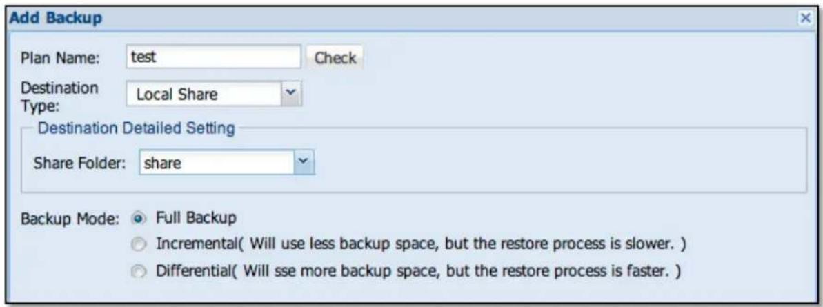
Figure 3.8.1-2 Add a Plan to Backup to a Local Share
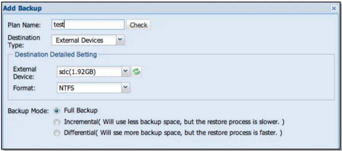
Figure 3.8.1-3 Add a Plan to Backup to Local External Device
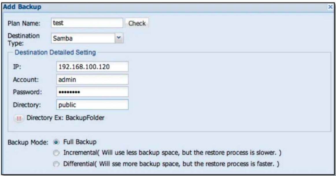
Figure 3.8.1-4 Add a Plan to Backup to Remote Samba (CIFS) Share
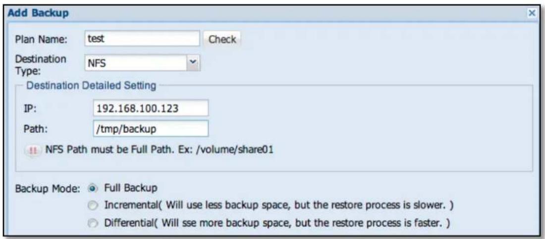
Figure 3.8.1-5 Add a Plan to Backup to Remote NFS Share
Backup Mode: Default mode is a Full Backup. There are three options: Full Backup, Incremental, and Differential
After setup is completed, click 'Next' to choose the share folder to be backed up.
Step 2: From the Source File, select the file(s) or share folder(s) to be backed up. Then click the Add icon 📋. The selected file(s) or share folder(s) will be added to the Backup File list. Click 'Next' to go to the Backup Plan Summary page for confirmation.
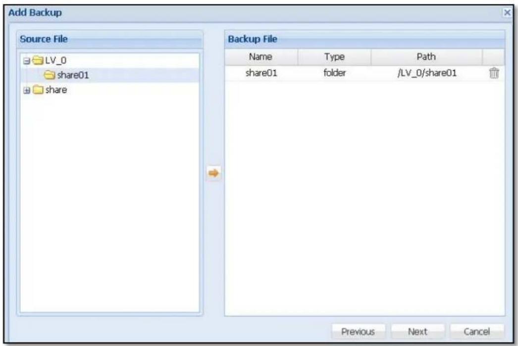
Figure 3.8.1-6 Step 2: Select Share Folder or File to Add to the Backup File List
Step 3: In Backup Plan Summary page, check the backup plan setup if correct or need to be modified. Click 'OK' when done. The new backup plan will be created.
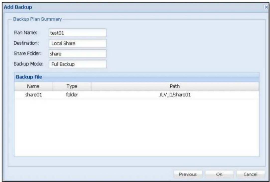
Figure 3.8.1-7 Step 3: Confirm to Add New Backup Plan
Restore:
Select the backup plan name or click 'Show All Plan Backup Record', and previous backup records will be shown (Figure 3.8.1-8). To restore a previous backup record, click the restore icon 📄 on the right side. A confirmation screen will appear. Make sure the destination folder has enough space. Click 'Yes' to confirm. The Restore Backup page (Figure 3.8.1-9) will appear. Select the folders or files you want to be restored and click the Add icon 📋. The selected files or folders will appear on the Restore File list. Finally select the destination share folder in 'Destination'. Click 'Restore' when done. The backup data will be restored to the specified destination share folder.
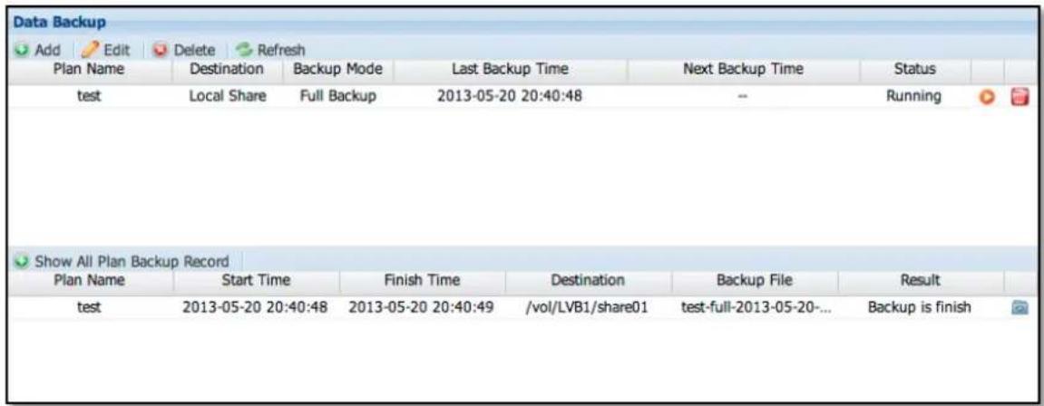
Figure 3.8.1-8 Data Backup Plan List and Record List
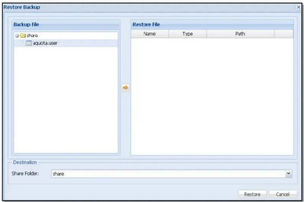
Figure 3.8.1-9 Select the Share Folders and/or Files to be Restored
Edit: Select the backup plan name you want to be modified and click 'Edit'. Click 'Next' to modify the backup plan.
Edit Backup Source File: Under 'Source File' list, select the file or share folder you want to be added for backup and click the Add icon. The selected file or folder will appear on the 'Backup File' list on the right. To delete a file or folder from Backup File list, click the delete icon on the right of the file or folder. When done, click 'Next' to go to Back Plan Summary page.
Back Plan Summary:
Check the backup plan setup if correct or still need to be modified. Click 'OK' when done. The backup plan settings will be updated.
Delete Backup Plan: Click the delete icon 📋 on the right side of the backup plan name to be deleted (Figure 3.8.1-1). The Confirm window will appear. Click 'Yes' to confirm deletion of the selected backup plan.
The backup plan can also be defined with scheduled job in Schedule manager. (See Chap 3.4.8)
3.8.2 Data Copy
Data Copy is similar to Data Backup but doing only 1:1 copy to another destination. It creates a full and exact copy of the selected data. The Share Copy backup function supports full copy backup of selected shared folder to backup destination device. It also supports scheduled backup for automatic backup. Supported backup destinations are: Local Share folder in NAS, External Devices such as USB external disk, Samba (SMB/CIFS) remote share folder, and NFS remote share folder.
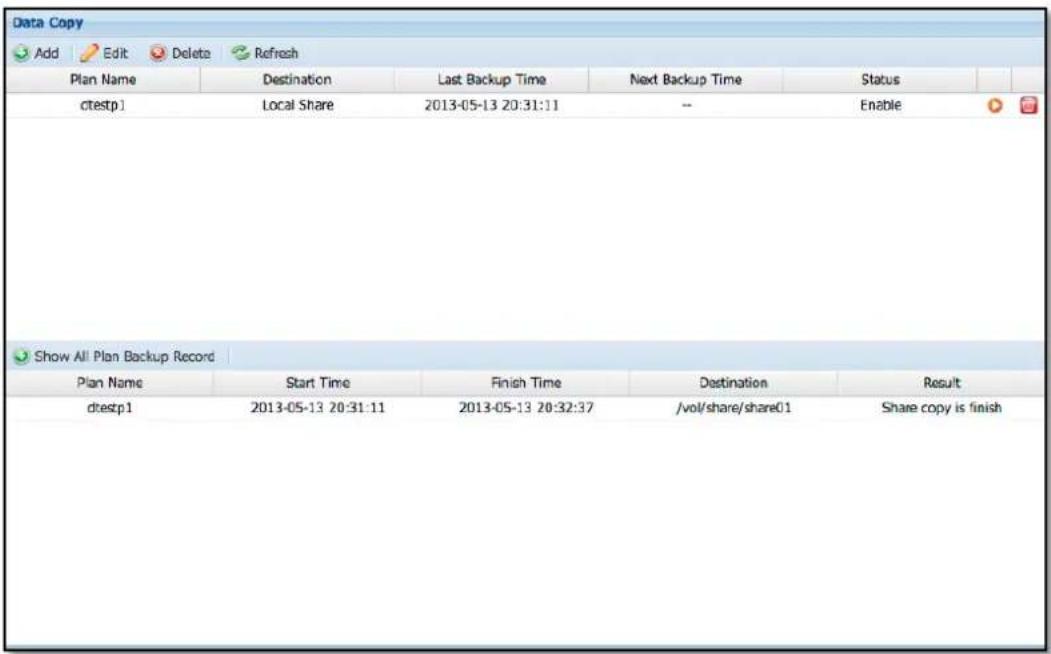
Figure 3.8.2-1 Data Copy Plan and Record List
The backup plan can also be defined with scheduled job in Schedule manager. (See Chap 3.4.8)
Add Share Copy Backup: Click the 'Add' icon. The Add Backup window will appear.
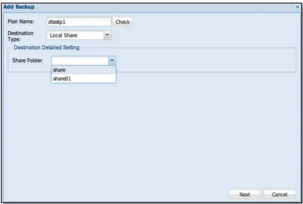
Figure 3.8.2-2 Step 1: Add a New Data Copy Plan
Step 1: Configure the basic backup plan settings, such as plan name and destination. Click 'Next' when done.
Plan Name: Enter the name of the backup plan. Plan name allows up to 32 characters, and can only contain letters, numbers, hyphen (-), and underscore (_). Space or period (.) is not allowed. Duplicate backup plan name is also not allowed.
| Destination Setting Description | ||
| Local Share | Share Folder | NAS Local share folder |
| External Devices | Ext_Device USB Disk | |
| Format | EXT3/NTFS /Not format. If set as EXT3 or NTFS, in the first backup, system will format the external device as EXT3 or NTFS. If set as “Not format”, system will automatically recognize the external device's file system format after auto-mount. | |
| Samba | IP | Remote Samba/CIFS share folder IP address |
| Account Login account | ||
| Password Login password | ||
| Path | Remote Samba/CIFS share folder name | |
| NFS | IP Remote NFS share folder IP address | |
| Path Remote NFS share folder name | ||
Step 2: Select the share folder or file to be backed up from Source File, and click the Add button. The selected share folder or file will appear on the Backup File list in the right. Click 'Next' to go to Backup Plan Summary confirmation page.
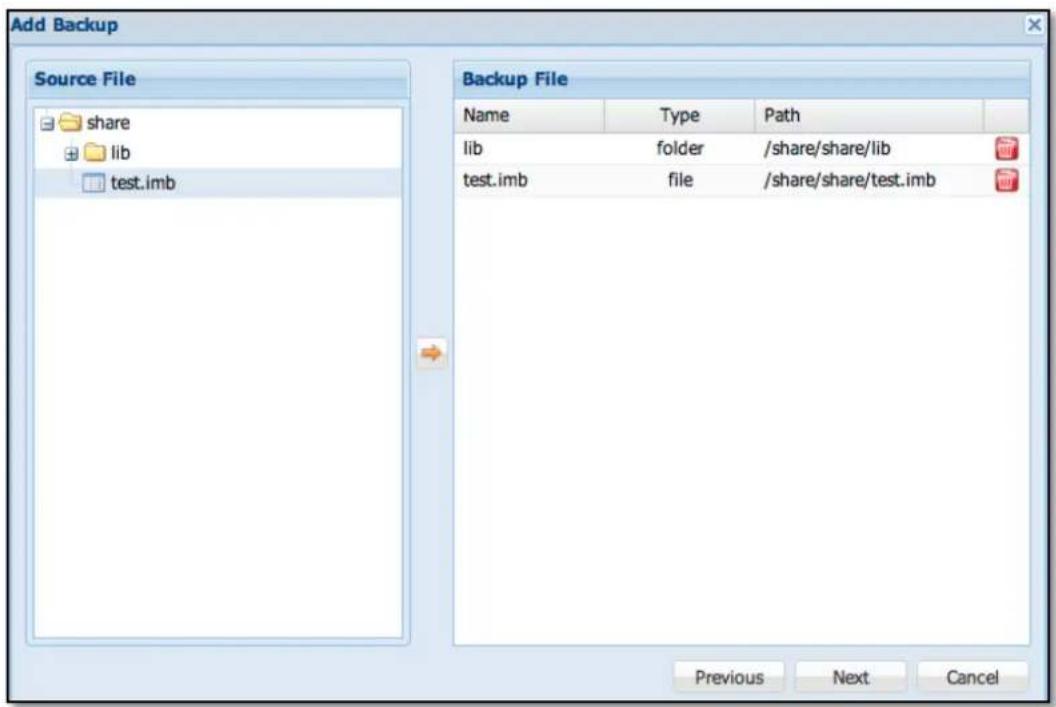
Figure 3.8.2-3 Step 2: Select Share Folder or File to Add to Backup File List
Step 3: In Backup Plan Summary page, check the backup plan setup if correct or need to be modified. Click 'OK' when done. The new backup plan will be created.
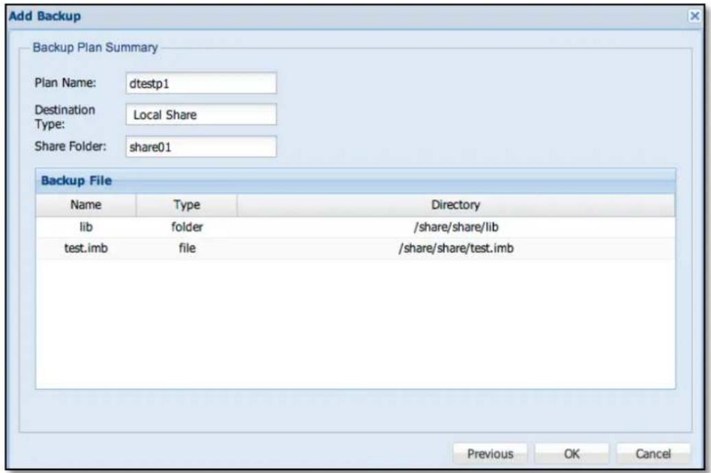
Figure 3.8.2-4 Step 3: Confirm to Add the New Backup Plan
Edit: Select the backup plan that you want to edit, and then click 'Edit' icon. Click 'Next' to modify the backup plan.
Edit Backup Source File: Under 'Source File' list, select the file or share folder you want to be added for backup and click the Add icon. The selected file or folder will appear on the 'Backup File' list on the right. To delete a file or folder from Backup File list, click the delete icon on the right of the file or folder. When done, click 'Next' to go to Back Plan Summary page.
Back Plan Summary: Check the backup plan setup if correct or still need to be modified. Click 'OK' when done. The backup plan settings will be updated.
Delete Back Plan: Click the delete icon 📋 on the right side of the backup plan name to be deleted (Figure 3.8.2-1). The Confirm window will appear. Click 'Yes' to delete the selected plan.
The backup plan can also be defined with scheduled job in Schedule manager. (See Chap 3.4.8)
3.8.3 Replication Backup
Replication Backup supports block-level replication of data from one logical volume of a NAS system to another logical volume of another NAS system. The two logical volumes, which are setup with Replication Backup, will be similar to a mirrored logical volume or Raid Level 1, and this enhances the logical volume data protection. When data is written on the source NAS logical volume, the data in the destination NAS logical volume is automatically synchronized. If the source NAS fails, administrator can manually switch and connect directly to the second NAS for continued data access.
| Replication Backup | ||||
| Add Edit | ||||
| Logical Volume | Port | Remote IP | Remote VG | Status |
| LV_6 | 5000 | 192.168.12.121 | VG01 | Replication need initial |
Figure 3.8.3-1 Replication Backup List
Add Replication Backup: Click 'Add'. The Add Replication window will be displayed. Set the options below and click 'OK' when done.
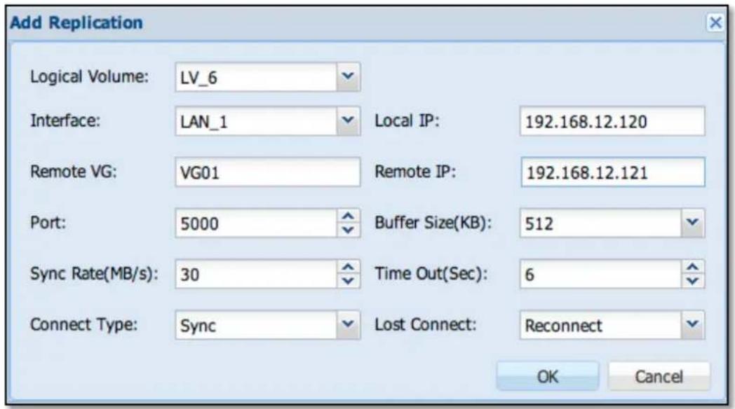
Figure 3.8.3-2 Add New Replication Backup
Logic Volume: Select which Volume will be replicated
Interface: Select which NAS Ethernet port will be used for Replication connection Local IP: Displays the local (source) NAS IP address that will be used for Replication.
Remote VG: Enter the VG name on the remote (destination) NAS where the replicated logical volume will be created
Remote IP: Manually enter the remote (destination) NAS IP address that will be used for Replication.
Port: Select a TCP port to bind locally and will be used to connect to the remote NAS.
Buffer Size (KB): It is the size of the TCP socket send buffer. You can specify smaller or larger values. Larger values are appropriate for reasonable write throughput with asynchronous protocol over high latency networks. Default is 512K and maximum is 2048K.
SyncRate (MB/s): This sets the limit of the bandwidth that will be used by the synchronization process. Default is 30MB/sec. Minimum value is 10MB/sec and maximum value is 1000 MB/sec – for high latency network environment (e.g. bonding on Gigabit Ethernet).
Time Out (Sec): It is the value to wait for connection timeout if the remote NAS has failed. If the remote NAS fails to send the response packet within the specified timeout time, the remote NAS will be considered dead and the TCP/IP connection is abandoned. The default is 6 sec. Minimum is 1 sec and maximum is 60 sec
Connection Type: There are two types of Replication Backup Connection:
Sync (Synchronous) - The system will acknowledge the transaction as completed after the data is written to the logical volume of destination NAS. It is recommended to use this mode. In most cases, this connection type preserves transaction semantics. Write IO is reported as completed if it has reached the remote logical volume.
Async (Asynchronous - for high latency network) - The system will acknowledge the transaction as completed after the data is written to system buffer. It provides faster transmission and is suitable for busy network. Write IO is reported as completed if it has reached the local TCP send buffer.
Lost Connect: When connection is lost, the Replication Backup can either go to stand-alone mode or will try to reconnect.
Reconnect: The Replication Backup will attempt to reconnect. (Default)
Stand-alone: The Replication Backup will not attempt to reconnect and will be in stand-alone state. All IO requests are only passed locally and no replication.

NOTE: Before Replication Backup is successfully created, a 4GB logical volume will be created on each NAS. This will serve as the metadata device for the replicated volume. This volume is not mounted and will not be seen on the NAS GUI. Please be sure to have an extra 4GB available VG space on both source and destination NAS.
Initialize or Edit Replication: Select the Logical Volume name in Replication Backup list, and then click 'Edit'. The Edit Replication window will appear.
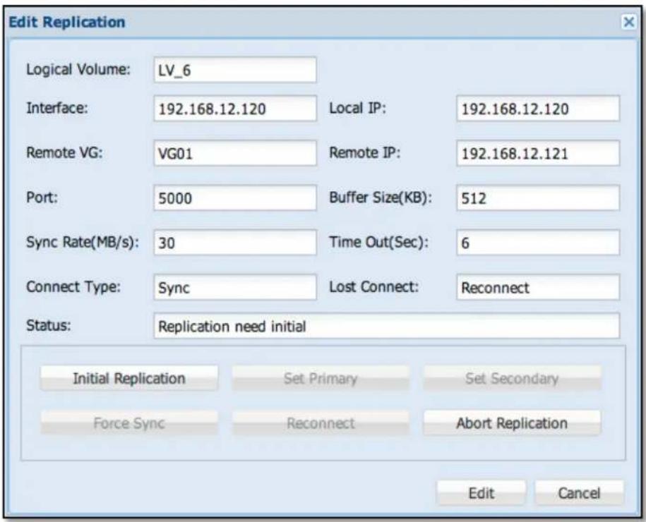
Figure 3.8.3-3 Modify Replication Backup
Initial Replication: Click "Initial Replication" to initialize the Replication Backup for the selected Logical Volume.
| Replication Backup | ||||
| Add Edit | ||||
| Logical Volume | Port | Remote IP | Remote VG | Status |
| LV_6 | 5000 | 192.168.12.121 | VG01 | cs:SyncSource 6.1% ro:Primary/Secondary ds:UpToDate/Inconsistent finish: 0:05:12 speed: 31,540 (31,540) K/sec |
Figure 3.8.3-4 Replication Backup Status

NOTE: After setup of Replication Backup on a logical volume in source NAS, a similar logical volume will be automatically created on the destination NAS under the specified VG. At this point, the Replication Backup is not yet initialized and no synchronization. Replication Backup still needs to be initialized first. After selecting "Initial Replication" button, the source NAS will then connect to the destination NAS and starts to synchronize. Synchronization typically takes quite a while especially on larger logical volume. After initialization, the source NAS should be in "Primary" state and the destination NAS should be in "Secondary" state. If this is the state, you have now a working Replication Backup. Initializing the Replication is done in the source NAS.
Set Primary: To set the replicated logical volume in destination (Secondary) NAS to be Primary, both NAS must be set first to Secondary state. This can be done by setting the Primary NAS to be Secondary. After both NAS becomes Secondary/Secondary, go to the NAS GUI of the destination NAS. Edit the replicated logical volume and use the "Set Primary" button.
Set Secondary: To set a Primary (source) logical volume to be Secondary (destination), use the "Set Secondary" button on the Primary NAS.
Force Sync: To manually force the synchronization, click the "Force Sync" button. The data on the primary NAS will be forcefully synchronized to the secondary NAS.
Reconnect: To reconnect a broken Replication Backup connection, click the "Reconnect" button. At some point in time, if Replication Backup fails to establish connection to the other NAS, you may try to re-establish connection thru this button. This button will be enabled only if one of the NAS losses connection.
Abort Replication: To abort or drop the replication, click the "Abort Replication" button. After aborting replication, the data on the destination logical volume (Secondary NAS) can be retrieved by accessing the share folder under that destination logical volume, and the share folder name is exactly the same as the share folder on the source logical volume (Primary NAS).

NOTE: Snapshot and Thin Provisioning volumes do not support Replication.
Extending Logical Volume Size under Replication Backup
The following are the steps:
- Abort the Replication Backup by selecting "Abort Replication" button.
- Delete the replicated logical volume on the destination (Secondary) NAS.
-
Extend the size of the source logical volume in primary NAS. Please note that there should be enough space on the VG of the destination NAS to accommodate the extended logical volume space. For example, if the size of source logical volume is now 3TB, the VG ("Remote VG") on the destination NAS must also have free 3TB space for creating the replicated logical volume (Note that after aborting replication, the same logical volume name can be deleted on the destination NAS to free up VG space).
-
Create a new Replication Backup using the extended logical volume on primary NAS.

NOTE:
Extending the size of a Logical Volume under Replication Backup is not allowed. However, there is a work around to extend the LV size. Note that the extended LV size must not exceed 16TB.
3.8.4 Snapshot Backup
Snapshot Backup creates a backup "copy" of a logical volume in specific moment in time. This feature is Block Level. Snapshot Backup also supports backup of iSCSI Target Volume and FC Target Volume, including scheduled backup.
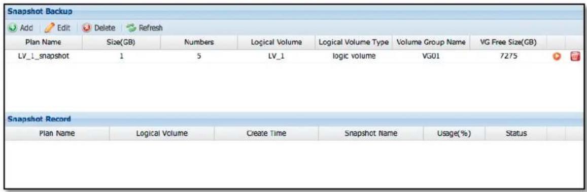
Figure 3.8.4-1 Snapshot Backup List
Add Snapshot: Click the 'Add' icon. The Add Snapshot window will appear. Enter the necessary information. Click 'OK' when done.
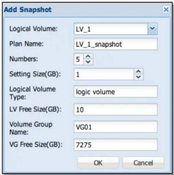
Figure 3.8.4-2 Create a New Snapshot Backup Plan
Logic Volume: Select the logical volume name that will be used to create Snapshot Backup.
Plan Name: Enter the name of the Snapshot Backup plan. The plan name can be up to 32 characters, and can contain only letters, numbers, hyphen (-), or underscore (_). Space or period (.) is not allowed. Duplicate plan name is also not allowed.
Numbers: This is the maximum number of snapshots. Default is 5. If the maximum number of snapshots is reached, for example there are now 5 snapshot backup, the next/newest snapshot will automatically overwrite the first/oldest snapshot.
Setting Size (GB): This is the capacity that will be used in each snapshot backup. If the amount of data in the logical volume exceeds the capacity that will be used for the snapshot, the snapshot backup will fail and can't be used. In order to avoid such case, it is advisable to set the snapshot capacity (Setting Size) the same as logical volume size.
Logic Volume Type: The system will automatically detect the type of logical volume, such as Default Volume, Logical Volume, Replication Volume, iSCSI Volume, or FC Volume (5 types). This information is for reference only and cannot be changed.
LV Free Size (GB): This is capacity of the selected logical volume. This information is for reference only and cannot be changed.
Volume Group Name: This is the volume group name where the selected logical volume was created. This information is for reference only and cannot be modified.
VG Free Size (GB): This is the free space of the volume group name where the selected logical volume exists. This information is for reference only and cannot be modified.

NOTE: If a logical volume is already used for Snapshot Backup, the logical volume can no longer be used to create another snapshot backup plan. Only one snapshot backup plan is allowed to be created in a logical volume.
Edit Snapshot: Select the Snapshot Backup plan name you want to edit and click the 'Edit' icon. The Edit Snapshot window will appear. Only the "Numbers" and "Setting Size (GB)" can be modified. Click 'OK' when done. The changes will be updated to the snapshot backup plan.
Delete Snapshot Backup Plan: Click the delete icon 📋 on the right of the snapshot backup plan name to be deleted. The Confirm window will appear. Select the 'Yes' button to confirm deletion.
Delete Snapshot Backup Record: Click the delete icon 📋 on the right of the snapshot backup record to be deleted. The Confirm window will appear. Select the 'Yes' button to confirm deletion.
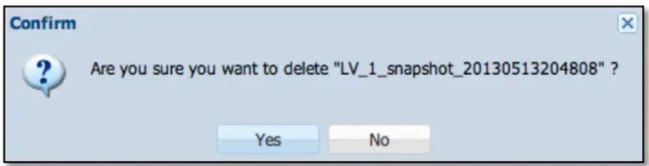
Figure 3.8.4-3 Confirm Message to Remove a Snapshot Backup Record
Restore Snapshot: Select the Plan Name that has the snapshot backup to be restored. The previous snapshot backups will appear in the Snapshot Record list. Click the 'Restore' icon on the right of the snapshot backup to be restored (Figure 3.8.4-4). The Snapshot Restore window will appear (Figure 3.8.4-5).

NOTE: Only snapshot backups of logical volumes can be restored. Snapshot backups of iSCSI volumes or FC volumes cannot be restored. However, there is a work around in order to access the data from snapshot backup, and that is to create an iSCSI or FC target volume using the snapshot backup volume (of the iSCSI volume or FC volume), and then connect the client computer to the iSCSI or FC target volume.
Select "Select File Restore" to restore specific files or folders only and click 'OK'. The Confirm window will appear (Figure 3.8.4-7). Click 'Yes'. The Restore Snapshot window will appear (Figure 3.8.4-8). Select the folder or file you want to be restored, choose the Destination folder and click 'Restore'. Data will be restored to the Destination folder.
Select "Full Volume Restore" and click 'OK'. The Confirm window will appear (Figure 3.8.4-6). Click 'Yes' to restore full volume data.
| Snapshot Backup | |||||||
| Add Edit Delete Refresh | |||||||
| Plan Name | Size(GB) | Numbers | Logic Volume | Logic Volume Typ | Volume Group Na | VG Free Size(GB) | |
| share_snapshot | 1 | 5 | share | logic volume | VG01 | 2284 | |
| Snapshot Record | |||||||
| Plan Name | Logic Volume | Create Time | Snapshot Name | Usage(%) | Status | ||
| share_snapshot | share | 2012-09-13 11:41:... | share_snapshot_20... | 0 | active | ||
| share_snapshot | share | 2012-09-13 11:41:... | share_snapshot_20... | 0 | active | ||
Figure 3.8.4-4 Snapshot Record List
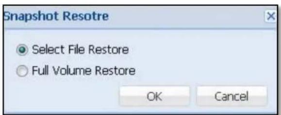
Figure 3.8.4-5 Snapshot Restore Option
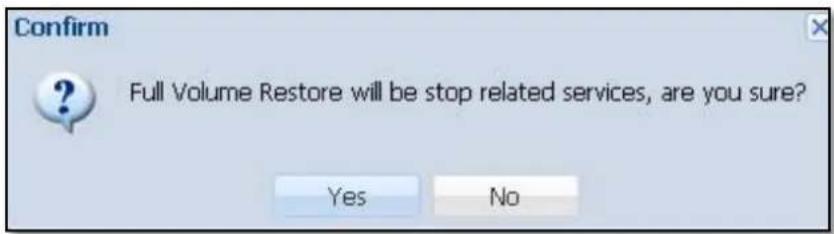
Figure 3.8.4-6 Confirm Message of Full Volume Restore Snapshot
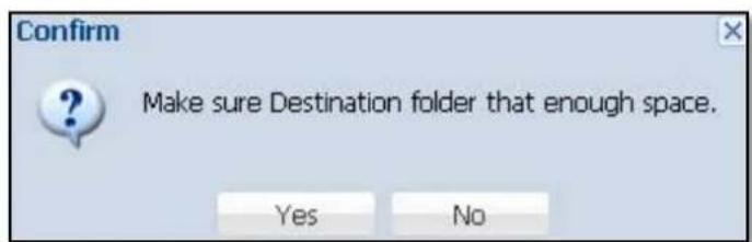
Figure 3.8.4-7 Confirm Message to Restore Snapshot
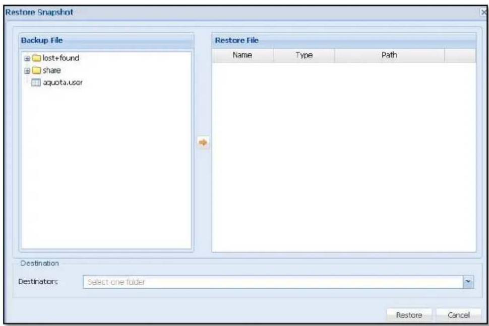
Figure 3.8.4-8 Select Share Folder or File to Restore
The Snapshot backup plan can also be defined with scheduled job in Schedule manager. (See Chap 3.4.8)
3.8.5 Volume Clone
Volume Clone can create fast replicate copy of one volume locally. One copy and up to three copies can be created.
Clone Status: Status of clone job. If it shows Ready, a new clone can be created.
Step 1: Select Clone Source: Select the original volume which can be general data volume, iSCSI or FC volumes. (Figure 3.8.5-1)
Step 2: Select Clone Destination: Select volume group to create the new volume clone copy, define the name of new volume clone. If you want to clone more than one copy, Click "Add" Figure 3.8.5-2). The maximum number of clones is 3.
After configure, click "Start". The system will start cloning the volume after confirming the Clone Summary (Figure 3.8.5-3).
While cloning, you can see the volume clone status (Figure 3.8.5-4).

NOTE: Snapshot and Thin Provisioning volumes do not support cloning.
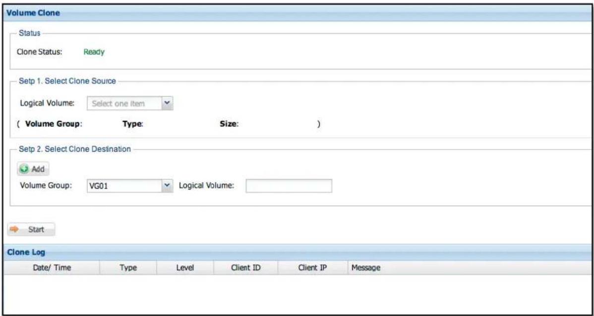
Figure 3.8.5-1 Clone Manager
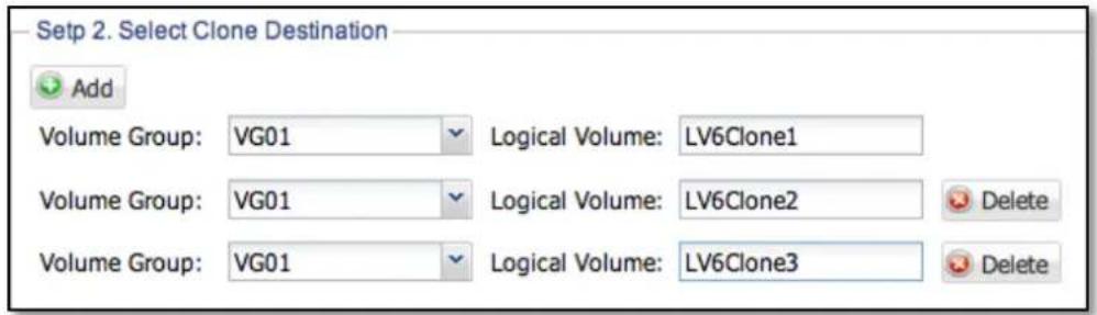
Figure 3.8.5-2 Clone More Than One Copy
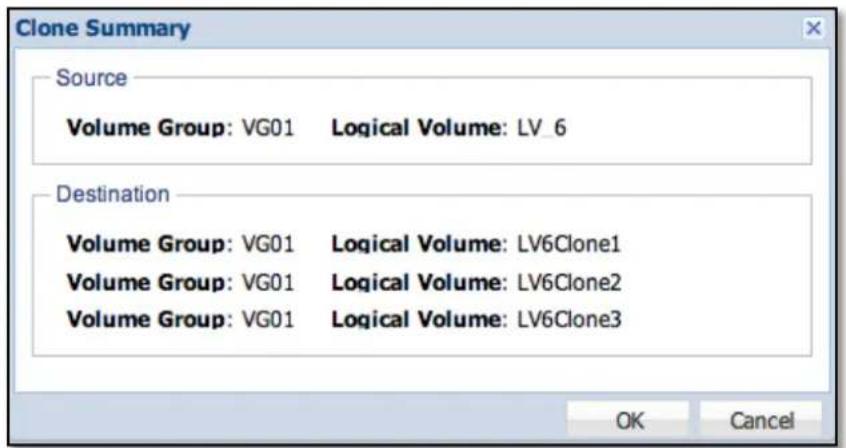
Figure 3.8.5-3 Confirm Message to Clone Volume
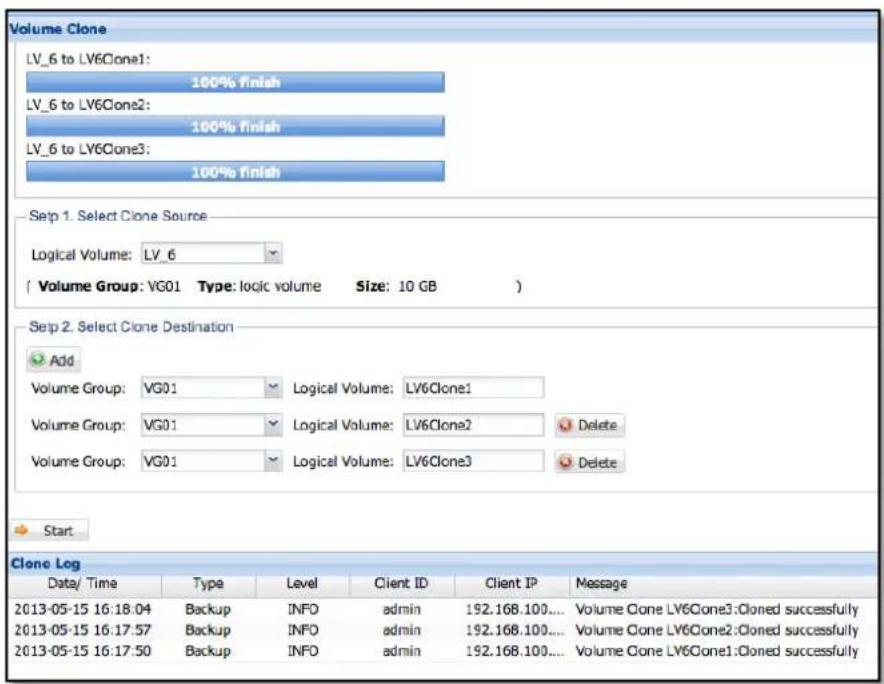
Figure 3.8.5-4 The Status after Clone Volume
3.8.6 Rsync Backup
Rsync is one of the popular remote backup solutions. Admin can use Rsync to upload whole local share to remote share or download files from remote share. You can create an Rsync backup plan by clicking "Add" button.

Figure 3.8.6-1 Rsync Backup
To add a new Rsync backup plan, the following need to be defined:
Plan Name: The name of Rsync plan. The name must be unique.
Local Share Folder
Share Folder: Select local share to do upload or download
Remote Share Folder
IP: the remote Rsync server IP
Account: the remote login name
Password: the login password
Path: The name or path of remote share
Mode: Specify to upload or download
Parameter: You can also define your own Rsync parameter here. Click "..." button to setup additional options.
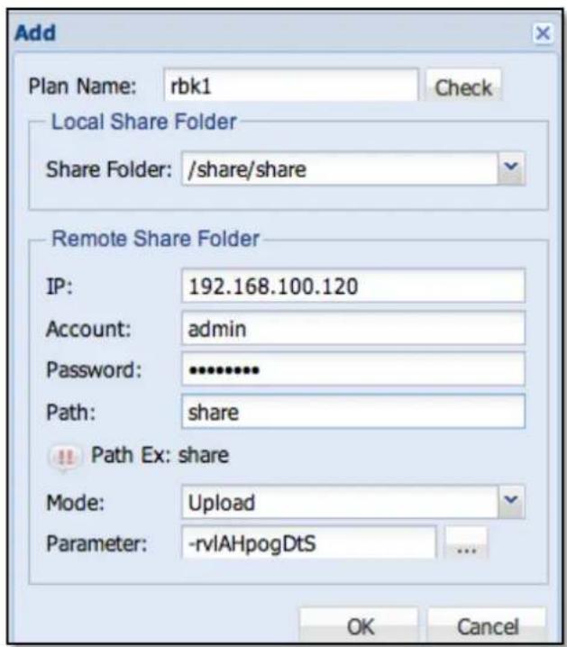
Figure 3.8.6-2 Options to Create Rsync Backup Plan
After Rsync backup plan is created, you will see the new plan in the list. If need to modify Rsync options, just select the plan and click 'Edit'.
To immediately do Rsync backup, click icon ▶ in the right column.
The Rsync backup plan can also be defined with scheduled job in Schedule manager. (See Chap 3.4.8)
3.8.7 System Configuration
System Configuration Backup can backup whole system configuration including Array, volumes, shares and accounts. You can import the backup configuration file to reconstruct the NAS configuration as before.
Configuration Backup: Click "Backup" button to backup the latest system configuration and create a backup configuration file, for example nas-config.tgz. Configuration Restore: Click "Select File" to select a backup configuration file to restore.
Before restore, the system must be started with factory default settings and without Array or volume.
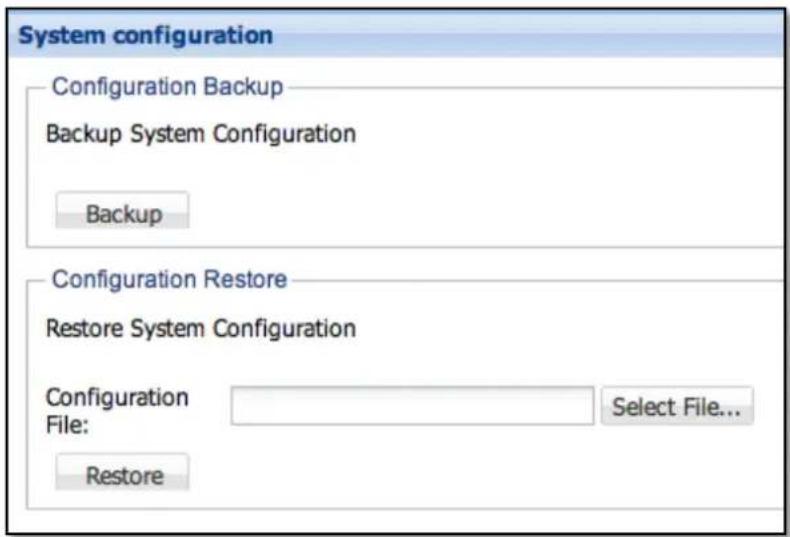
Figure 3.8.7-1 System Configuration Backup and Restore
3.8.8 Amazon S3
Amazon S3 (Simple Storage Service) is provided by the Amazon Pay online storage services. NAS users through support for Amazon S3 to backup your important data to Amazon S3, or download the data from Amazon S3 and to the NAS. Addition, users can also function with built-in scheduler to set automatic backup task
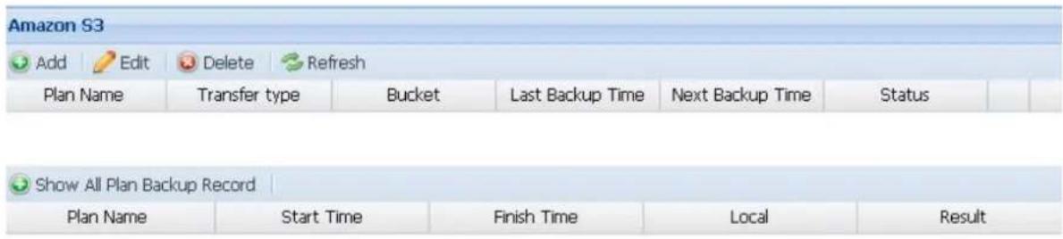
Figure 3.8.8-1 Amazon S3
Add Amazon S3 backup plan: To add a new Amazob S3 backup plan, the following need to be defined.
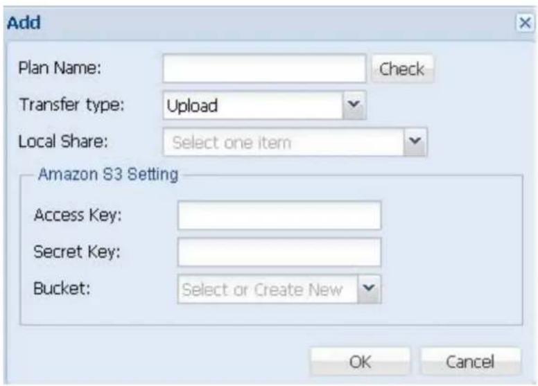
Figure 3.8.8-2 Add Amazon S3
Plan name: Amazon S3 project name, the name must be unique.
Transfer type: upload or Download Select local shared upload or download
Local Folder: Select the files needed to synchronize local folder
Amazon S3 information:
Access key: enter the access key
Secret key: Enter the passkey
Bucket: When you have entered the correct information, you will be imported into your account. Or create a new "Create New" and enter the bucket name, for example: backup. Be created in any folder under the root directory is your buckets. Your bucket name must be unique, meaning that all other users of the S3 bucket differently. All files and folders will be stored in buckets in.
Get Amazon S3 account
Step 1: Registration Amazon Web Services account
Before using this service, you need to first obtain a personal Amazon S3 account (http://aws.amazon.com/s3/). For details about the fees, see the Amazon web services website.
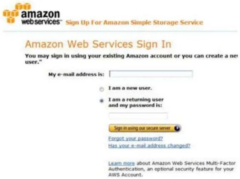
Step 2: Get your Access Key ID and Secret Access Key
When you have completed the account application process, you will receive part of your Access Key ID and Secret Access Key. Please keep this ID and key.
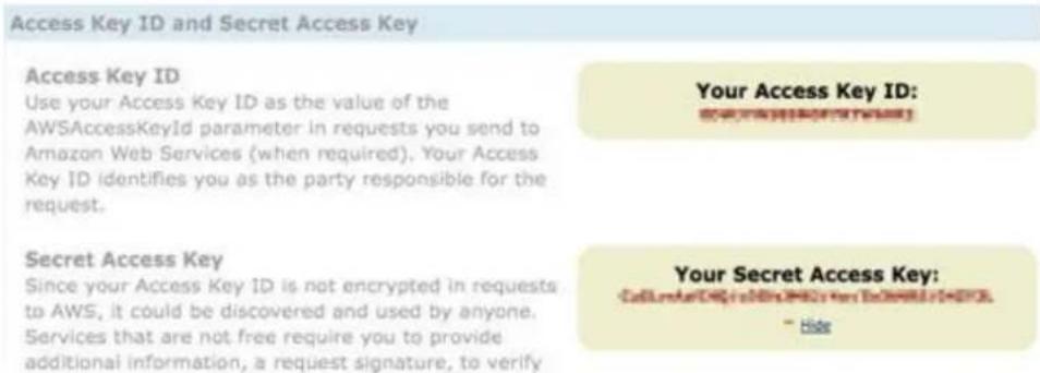
If you accidentally lost your Access Key ID and Secret Access Key, please click on "Your Account" and select "Security Credentials" to regain.
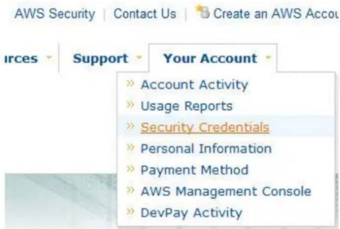
You can use the "Your Account" option at any time to review your account status, payment information, and change your personal information.
3.9 Attached Device Manager
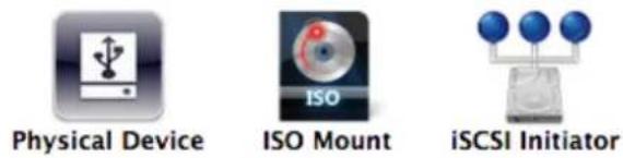
3.9.1 Physical Device
When USB or eSATA storage device is attached to the NAS, the NAS detects it as Physical Device (Figure 3.9.1-1). This device can be mounted and exported as a Samba share folder (Figure 3.9.1-4). The detected device is also available as backup destination.
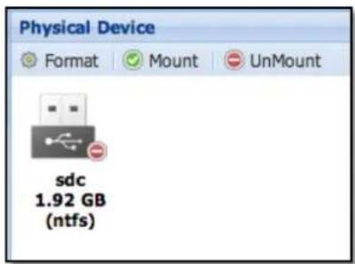
Figure 3.9.1-1 Physical Device Manager
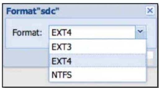
Figure 3.9.1-2 Format Attached Device
Format: The device can be formatted with NTFS, EXT3 or EXT4 file system.
Mount: If system recognized the file system in the attached device, it can be mounted as Samba share folder.
Umount: Un-mount the device. The device will no longer be defined in Samba service.

Figure 3.9.1-3 Mount and Share Attached Device
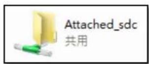
Figure 3.9.1-4 If Mounted, Attached Device can be Accessed from Windows Clients

NOTE: Please make sure the device is un-mounted before it is deattached from NAS unit.
3.9.2 ISO Mount
You can pick an ISO file in NAS then mount and export it as a Samba share (Figure 3.9.2-4).
Add: Click to select a ISO File in the list. (See Figure 3.9.2-2)
Delete: Remove the ISO File from list.
Mount: Mount the ISO File and share it to a Samba share list (See Figure 3.9.2-3)
Umount: Umount the ISO File and remove from Samba share list
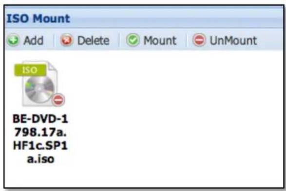
Figure 3.9.2-1 ISO Mount
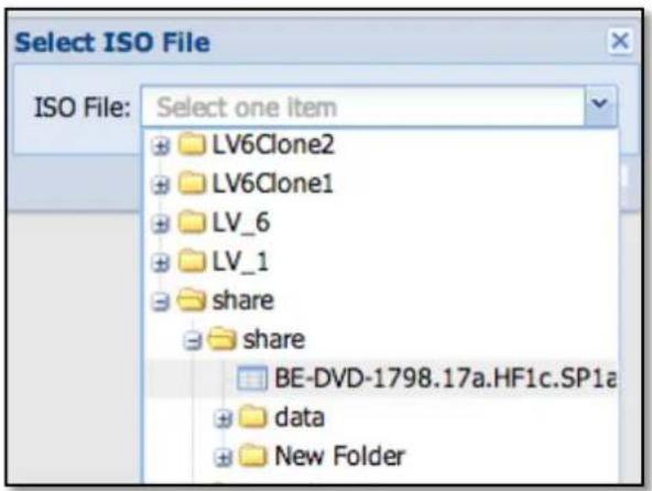
Figure 3.9.2-2 Select ISO file
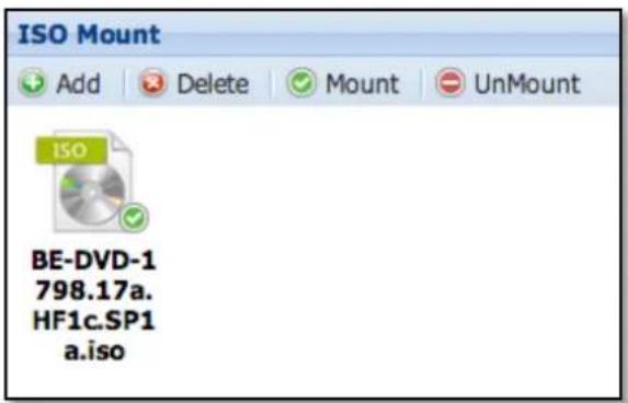
Figure 3.9.2-3 Mount and Share ISO File
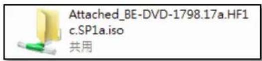
Figure 3.9.2-4 ISO Share in Samba
3.9.3 iSCSI Initiator
iSCSI Initiator allow admnb to connect to iSCSI target, mount iSCSI volume, format and export it as a Samba share (Figure 3.9.3-5)
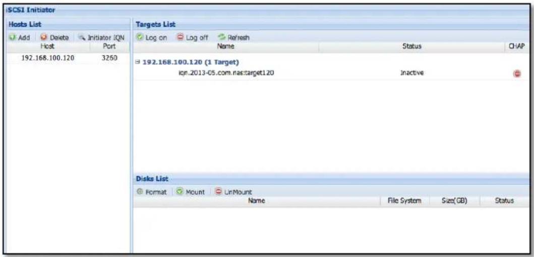
Figure 3.9.3-1 iSCSI Initiator
Host List: (See Figure 3.9.3-1)
List All known iSCSI host list
Button in Host list
Add: Assign a new iSCSI host in list.
Delete : Remove a host from list
Initiator IQN: Some iSCSI target require IQN to logon. Enter the IQN for the iSCSI host
After adding host, the target(s) will be displayed in the Targets List on the right.
Target List (See Figure 3.9.3-1)
List all targets from Hosts List.
Logon : Logon to Target and get all iSCSI disks list. (See Figure 3.9.3-2)
Logoff : Logoff from Target and release all iSCSI disks.
Refresh: Refresh the target list.
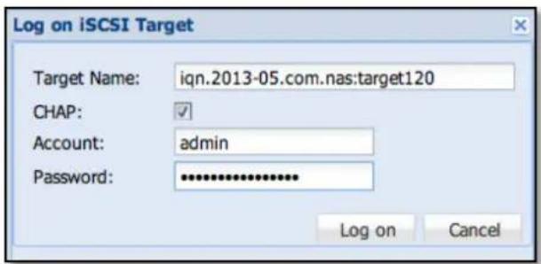
Figure 3.9.3-2 Log on iSCSI Target
After logon target successfully, all iSCSI Disks will be shown in the Disks List. (Figure 3.9.3-3)
Format: Format the iSCSI disk with EXT3, EXT4 or NTFS. (See Figure 3.9.3-4) Mount: Mount the iSCSI disk and show in Samba share list. (See Figure 3.9.3-5) Umount: Umount iSCSI disk and remove from Samba share list.
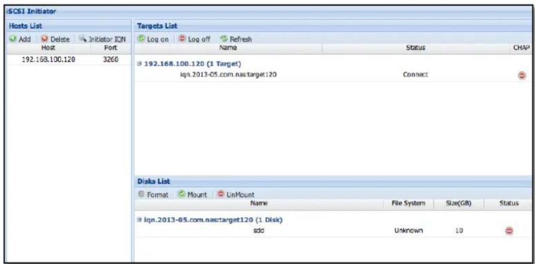
Figure 3.9.3-3 Disks List from iSCSI Target
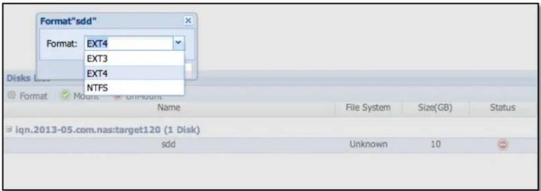
Figure 3.9.3-4 Format the iSCSI Disk
Figure 3.9.3-5 iSCSI Disk Share in Samba
3.10 Plug-in Manager

The Plug-in Manager is for installing other software like backup agent, HA services, etc. Current Plug-in modules are CA ARCserve Backup Agent, NetVault Backup Agent, Symantec Backup Exec Agent, CDP Agent and HA.
How To install
Please ask your vendor to get the latest plug-in modules.
Go to Plug-in Center and click "Add Plug-in Application" button at the upper right side (Figure 3.10.1).
Choose what plug-in (Figure 3.10.2) to install then select plug-in file (Figure 3.10.3) to upload and install.
While installing, the status will be shown as Figure 3.10.4, After install successful the new service will show up in Plug-in center (Figure 3.10.5).
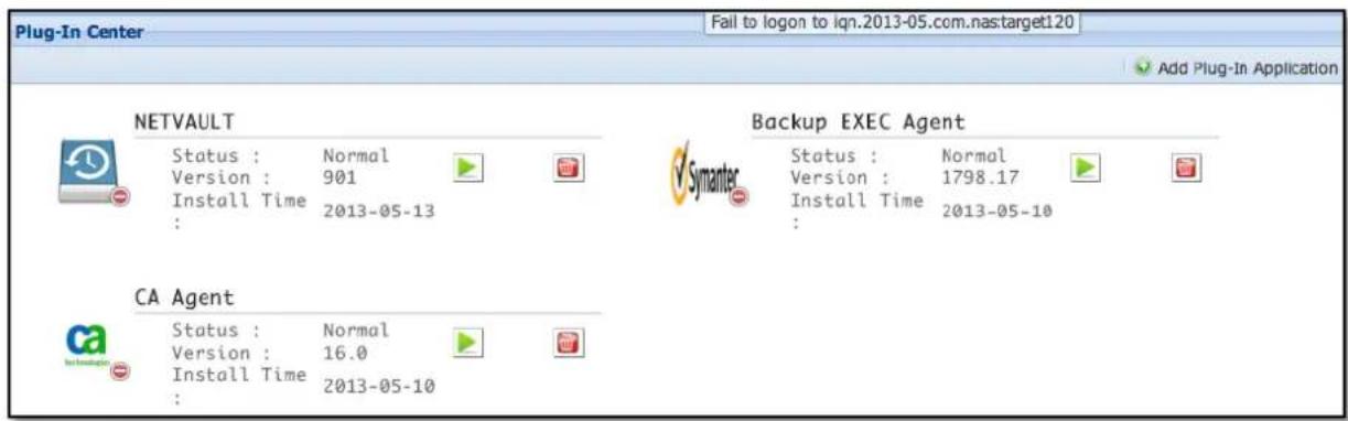
Figure 3.10-1 Plug-in Manager
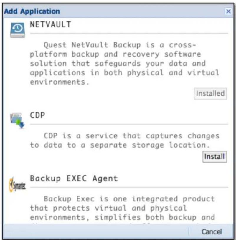
Figure 3.10-2 Choose and Add Plug-in Application
Figure 3.10-3 Select Plug-in File to Install
Figure 3.10-4 Status of Installing a Plug-in Application
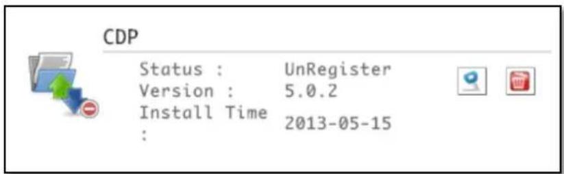
Figure 3.10-5 Plug-in Service Status after Install
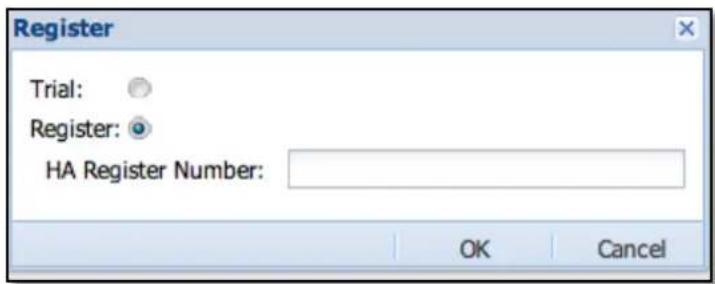
Figure 3.10-6 Register or use Trial Version (Trial Period)
After Backup Agents is installed, it needs a related backup server to connect to. Please contact the vendor of backup server for more information.
Register:
Some modules like CDP and HA needs to be registered (Figure 3.10.6). Please contact the NAS vendor to get detailed information. You can test the functions as a "Trial" version, and allows you to test within 30 days trial period.

NOTE: Installing un-official Plug-in modules is not allowed.
3.10.1 NAS HA
What's NAS HA?
NAS HA (High Availability) cluster provides solution for business continuity with real time, continuous data replication and synchronization, which ensures that if ever one NAS server/node becomes unavailable, due to failure or maintenance-related downtime, the remaining NAS server/node can still provide all services to client computers.
NAS HA can have 2-node HA cluster or 3-node HA cluster. All nodes in HA cluster are active. This means in a 2-node HA cluster, for example NAS-1 and NAS-2, resources from each node, such as NAS share folders, are accessible in both nodes. In 3-node HA cluster, all 3-nodes resources are also accessible in all 3 nodes.
NAS HA Architecture
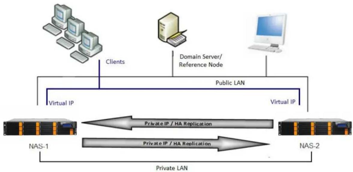
flowchart
graph TD
    A["Client 1"] -->|Clients| B["Public LAN"]
    C["Client 2"] -->|Private LAN| D["NAS-1"]
    E["Domain Server/Reference Node"] -->|Virtual IP| F["NAS-2"]
    B -->|Virtual IP| F
    D -->|Private IP / HA Replication| F
    G["Computer"] -->|Virtual IP| B
    style A fill:#f9f,stroke:#333
    style C fill:#f9f,stroke:#333
    style E fill:#f9f,stroke:#333
    style B fill:#ccf,stroke:#333
    style F fill:#ccf,stroke:#333
Figure 3.10.1-1 Two-nodes HA Cluster
In 2-node HA cluster, Logical Volumes in NAS-1 are replicated to NAS-2, and Logical Volumes of NAS-2 are replicated to NAS-1.
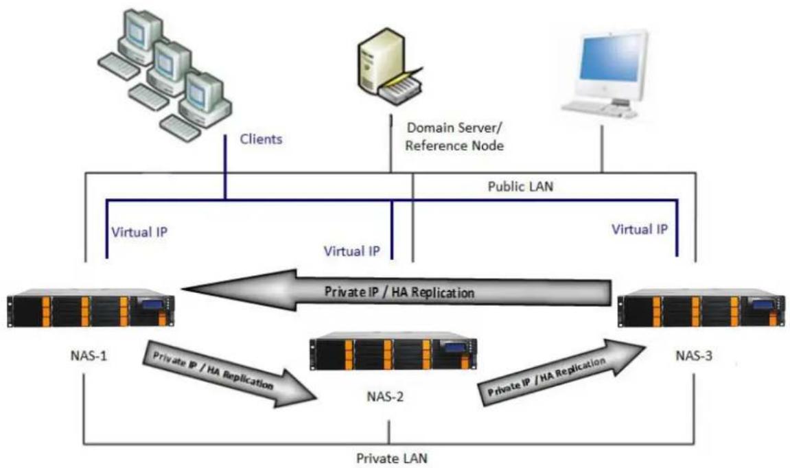
flowchart
graph TD
    A["Client Server"] -->|Clients| B["Virtual IP"]
    C["Domain Server/Reference Node"] -->|Public LAN| D["Virtual IP"]
    B -->|Private IP / HA Replication| E["NAS-1"]
    D -->|Private IP / HA Replication| F["NAS-2"]
    E --> G["Private LAN"]
    F --> G
    G --> H["NAS-3"]
    I["Computer"] --> A
    J["Desktop"] --> C
Figure 3.10.1-2 Three-nodes HA Cluster
In 3-node HA cluster, Logical Volumes in NAS-1 are replicated to NAS-2, Logical Volumes of NAS-2 are replicated to NAS-3, and Logical Volumes of NAS-3 are replicated to NAS-1.
NAS HA Setup Steps:
Configure NAS Host Names → Configure Network Settings → Configure Logical Volumes and Share Folders → Install NAS HA Plug-in → Setup HA and Start HA Service

NOTE: The VG (Volume Group, such as VG01) in each NAS nodes must have enough VG free space for other NAS node to replicate Logical Volumes. Check the size of Logical Volumes from each NAS node.
1. Configure NAS Host Names
In System Manager -> General -> GUI -> Host Name, change NAS host name.
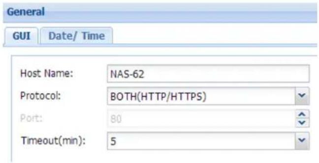
Figure 3.10.1-3 NAS Host Name

NOTE: The Host Name of NAS nodes cannot be the same, i.e., each NAS Host Name must be unique.
2. Configure Network Settings
In System Manager -> Network, configure LAN_0 and LAN_1 (default LAN ports).
NAS HA service needs 2 LAN interfaces:
Public IP - for NAS configuration, also for client access
Private IP – for HA replication and heartbeat
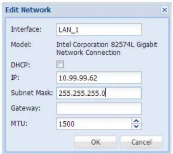
Figure 3.10.3-4 Configure Network Settings
Please see Section 3.4.2 Network for more information to configure IP address.
3. Configure Logical Volumes and Share Folders
Each NAS node requires least one Logical Volume to run HA.
In NAS GUI of one NAS node, go to Storage Manager -> Volume Group -> VG name (example: VG01), create Logical Volume, for example "LV_1". In Storage Manager -> Share, create share folder under the Logical Volume, for example "share01". In the other NAS node, create different Logical Volume name and Share Folder name.
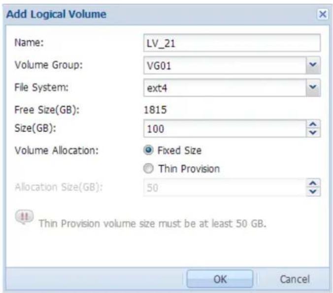
Figure 3.10.1-5 Add Logical Volume
Please refer to Chapter 3.5 Storage Manager for more information to configure LV and Share Folder.

NOTE: The Logical Volume names and Share Folder names can't be the same between nodes. For example, if NAS-1 has Logical Volume LV_1, then LV_1 must not exist in other NAS nodes, such as in NAS-2, or in NAS-3 (in case of 3-node HA cluster). If Share Folder "share01" is created in NAS-1, other NAS nodes cannot use same share folder name.

NOTE: When creating Logical Volumes, need to consider the size of the Logical Volume and the VG free space on the other NAS node. For example, in 2-node HA, NAS-1 has 5TB LV_1, and NAS-2 has 10TB LV_2. NAS-1 VG must have 10TB free space for LV_2 to replicate, and NAS-2 VG must have 5TB free space for LV_1 to replicate.
4. Install NAS HA Plug-In
When using NAS HA Cluster service, you need to install NAS HA Plug-in in each NAS node that will be included in cluster.
Steps:
a. Expand Plug-In Manager, and click "Plug-In Center".
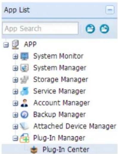
Figure 3.10.1-6 HA Plug-In Center
b. Click the "Add Plug-In Application" to start the installation wizard.
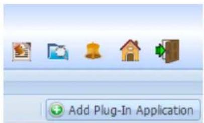
Figure 3.10.1-7 Add Plug-In Application
c. Click the "Install" button of HA item.
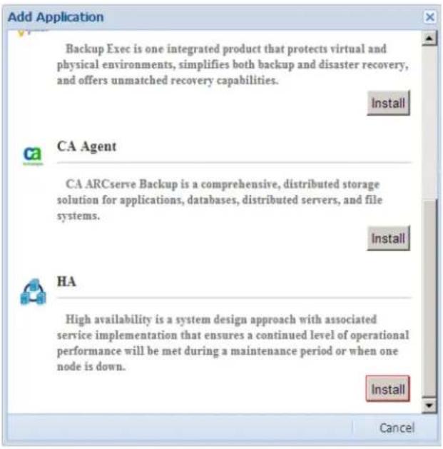
Figure 3.10.1-8 Install HA Plug-in
d. Click the "Browse" button to select the plug-in file, and click OK.
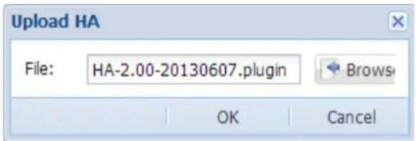
Figure 3.10.1-9 Select the HA Plug-in File
e. Installation is complete, click "Yes".
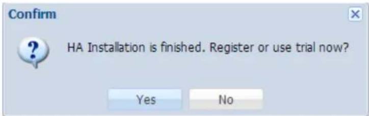
Figure 3.10.1-10 HA Plug-in Installation Done
f. You can select Trial, or Register and provide the license key file.
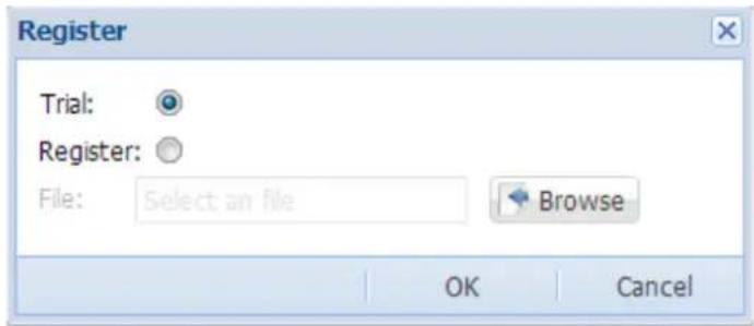
Figure 3.10.1-11 Select Trial or Register
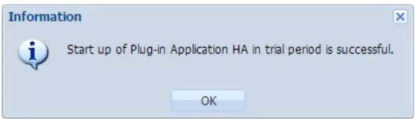
Figure 3.10.1-12 HA in Trial Period
5. Setup NAS HA and Start HA Service
a. Please expand Plug-In Manager, and click into "HA" page.
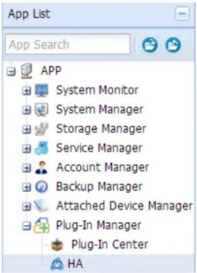
Figure 3.10.1-13 HA Plug-In
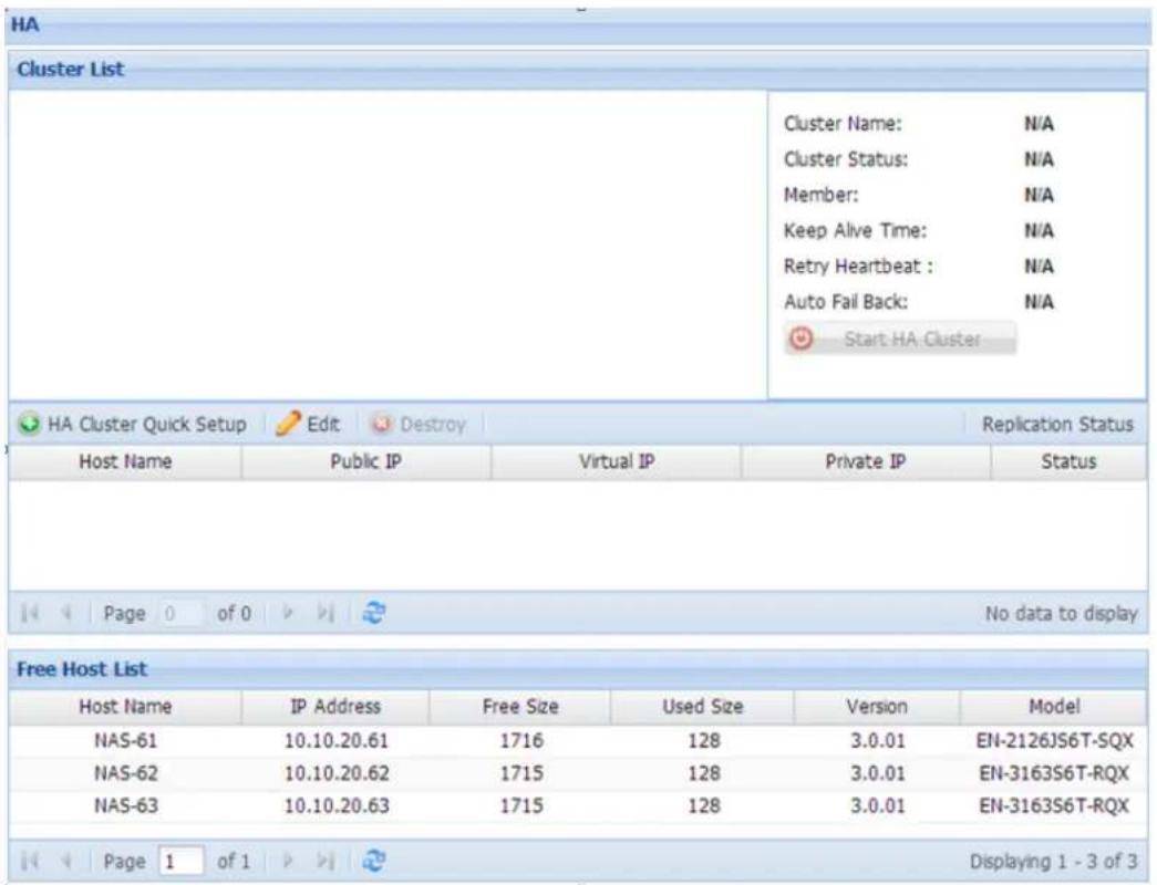
Figure 3.10.1-14 HA Setup Page
b. Click "HA Cluster Quick Setup"

HA Cluster Quick Setup
Figure 3.10.1-15 HA Cluster Quick Setup
c. Select NAS host names that will be included in HA cluster. Click Next.
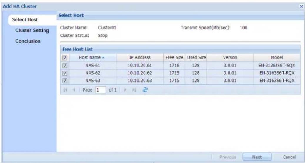
Figure 3.10.1-16 Select NAS Host Names
d. In Cluster Setting, setup the following:
Reference Node: IP address of other host or device on the network used to verify NAS network access or connectivity, such as domain server IP address or gateway IP address.
Virtual IP: Cluster IP address for client's access. Use the Virtual IP address to access Cluster resources, such as share folders of NAS nodes.
Public IP - for NAS configuration, also for client access
Private IP - LAN port for HA replication and heartbeat
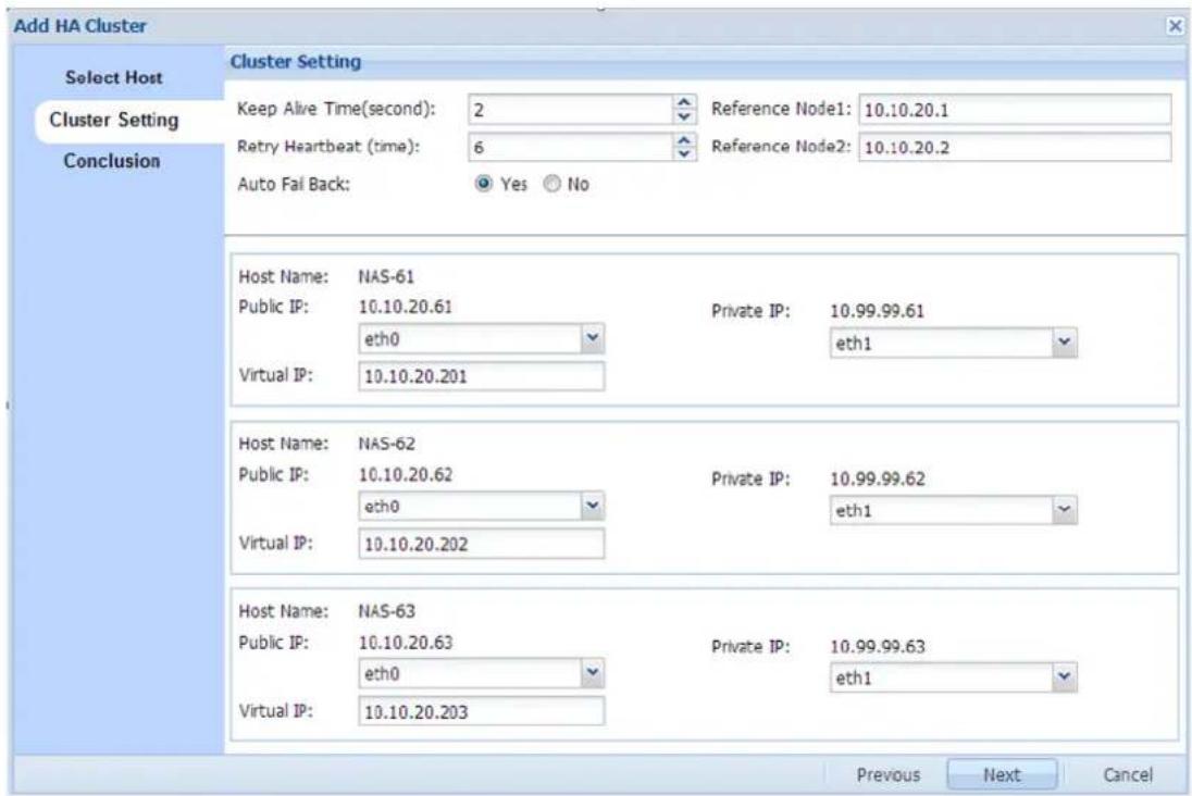
Figure 3.10.1-17 HA Cluster Setting
e. In "Conclusion page" verify all settings are correct and click "OK".
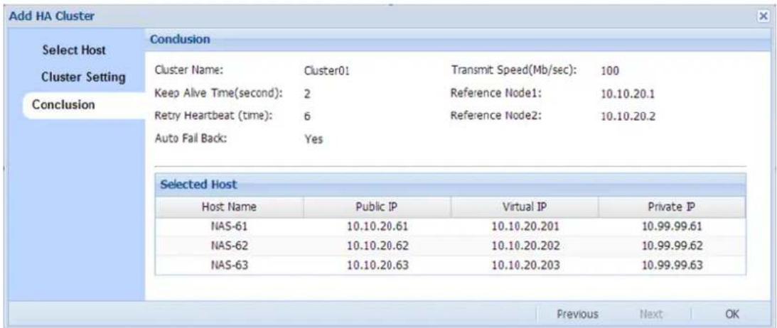
Figure 3.10.1-18 Conclusion Page
f. Confirm setting, and select "Start Cluster after creating cluster configuration" to automatically start HA service.
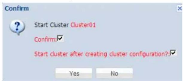
Figure 3.10.1-19 Confirm and Automatically Start HA Cluster
g. Cluster setup will be created. Please wait for several minutes (5 to 15 minutes).
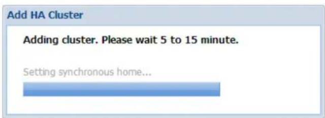
Figure 3.10.1-20 Adding Cluster
h. Logical Volumes in each node will be synchronized to other NAS node(s) and will show progress status "Initializing".
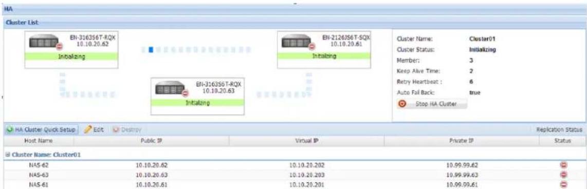
Figure 3.10.1-21 HA Cluster Initializing

NOTE: While the HA setup is initialized and Logical Volumes in each NAS node is synchronized to other node(s), the Sync status can be verified in Backup Manager -> Replication Backup.
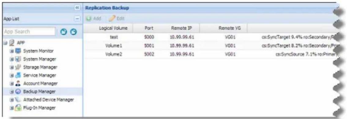
![Status rcTarget 9.4% ro:Secondary/Primary ds:Inconsistent/UpToDate [>............] synced: 9.4% (92848/102400)Mfinish: 0:51:38 speed: 30,672 (29,368) want: 30,720 K/sec rcTarget 8.2% ro:Secondary/Primary ds:Inconsistent/UpToDate [>............] synced: 8.2% (94040/102400)Mfinish: 0:54:04 speed: 29,676 (29,508) want: 30,080 K/sec rcSyncSource 7.1% ro:Primary/Secondary ds:UpToDate/Inconsistent [>............] synced: 7.1% (95188/102400)Mfinish: 0:53:31 speed: 30,348 (29,648) K/sec](/content/2026/05/954997/images/cc5f8058bcd06addb49063ef1bfddbe2deda785a616fe0feffbb88775c0fadd8.jpg)
Figure 3.10.1-22 Sample Replication Sync Status of Logical Volumes

NOTE: If Logical Volumes is not yet finished synchronizing to other NAS node and one NAS node fails, the HA Fail-Over function will not work properly.
i. When synchronization is complete, status will show "active". HA service is working properly.
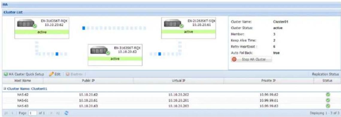
Figure 3.10.1-23 HA Cluster Status is Active

NOTE: When NAS nodes status show "active", it means HA is working. One NAS node can fail and the other NAS node can still provide the resources from failing NAS node after fail-over.
HA Fail-Over
When one NAS node becomes unavailable, due to some problem such as hardware failure, there is about 5 minutes fail-over time for the Virtual IP of failing NAS node. After about 5 minutes, the remaining NAS node will have taken over, and the Virtual IP of the failing NAS node will become accessible again.
Fail-Over Scenario
When one NAS node fails, the other NAS node will take over. In the example below with 3-node HA cluster, when server A fails, after fail-over to server B, the resources (i.e. Logical Volumes and share folders) from server A will be accessible again from server B. Connect/access using the same Virtual IP of server A.
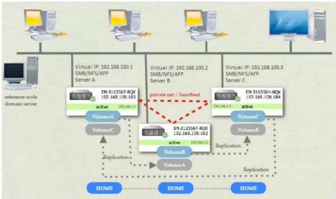
flowchart
graph TD
    subgraph_Server_A["Virtual IP: 192.168.100.1\nSMB/NFS/AFP\nServer A"]
        A1["VolumeA"] -->|Replication| A2["VolumeB"]
        A2 -->|Replication| A3["VolumeC"]
        A3 -->|Replication| A4["VolumeA"]
        A4 -->|Replication| A5["VolumeB"]
        A5 -->|Replication| A6["VolumeC"]
        A6 -->|Replication| A7["VolumeA"]
        A7 -->|Replication| A8["VolumeB"]
        A8 -->|Replication| A9["VolumeC"]
        A9 -->|Replication| A10["VolumeA"]
        A10 -->|Replication| A11["VolumeB"]
        A11 -->|Replication| A12["VolumeC"]
        A12 -->|Replication| A13["VolumeA"]
        A13 -->|Replication| A14["VolumeB"]
        A14 -->|Replication| A15["VolumeC"]
        A15 -->|Replication| A16["VolumeA"]
        A16 -->|Replication| A17["VolumeB"]
        A17 -->|Replication| A18["VolumeC"]
        A18 -->|Replication| A19["VolumeA"]
        A19 -->|Replication| A20["VolumeB"]
        A20 -->|Replication| A21["VolumeC"]
        A21 -->|Replication| A22["VolumeA"]
        A22 -->|Replication| A23["VolumeB"]
        A23 -->|Replication| A24["VolumeC"]
        A24 -->|Replication| A25["VolumeA"]
        A25 -->|Replication| A26["VolumeB"]
        A26 -->|Replication| A27["VolumeC"]
        A27 -->|Replication| A28["VolumeA"]
        A28 -->|Replication| A29["VolumeB"]
        A29 -->|Replication| A30["VolumeC"]
        A30 -->|Private net / heartbeat| B
    end
Figure 3.10.1-24 Three-node HA Cluster
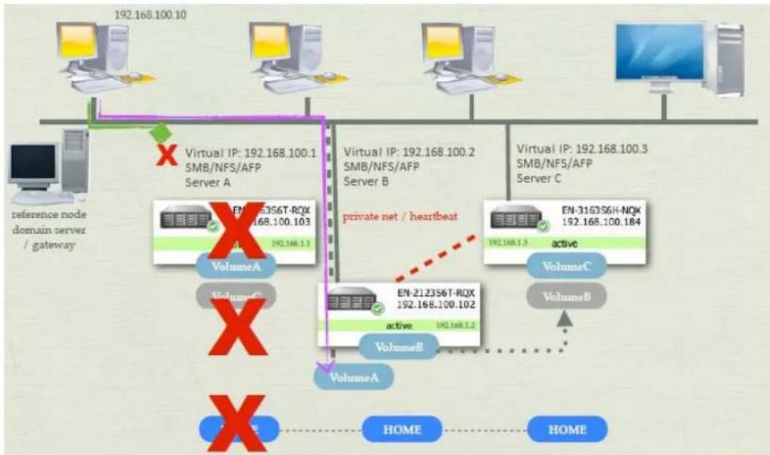
flowchart
graph TD
    A["reference node domain server / gateway"] --> B["Virtual IP: 192.168.100.1 SMB/NFS/AFP Server A"]
    B --> C["VolumeA"]
    C --> D["VolumeB"]
    D --> E["VolumeC"]
    E --> F["VolumeB"]
    F --> G["VolumeA"]
    G --> H["VolumeB"]
    H --> I["VolumeC"]
    I --> J["VolumeB"]
    J --> K["VolumeA"]
    K --> L["VolumeB"]
    L --> M["VolumeC"]
    M --> N["VolumeB"]
    N --> O["VolumeA"]
    O --> P["VolumeB"]
    P --> Q["VolumeC"]
    Q --> R["VolumeB"]
    R --> S["VolumeA"]
    S --> T["VolumeB"]
    T --> U["VolumeC"]
    U --> V["VolumeB"]
    V --> W["VolumeA"]
    W --> X["VolumeB"]
    X --> Y["VolumeC"]
    Y --> Z["VolumeB"]
    Z --> AA["VolumeA"]
    AA --> AB["VolumeB"]
    AB --> AC["VolumeC"]
    AC --> AD["VolumeB"]
    AD --> AE["VolumeA"]
    AE --> AF["VolumeB"]
    AF --> AG["VolumeC"]
    AG --> AH["VolumeB"]
    AH --> AI["VolumeA"]
    AI --> AJ["VolumeB"]
    AJ --> AK["VolumeC"]
    AK --> AL["VolumeB"]
    AL --> AM["VolumeA"]
    AM --> AN["VolumeB"]
    AN --> AO["VolumeC"]
    AO --> AP["VolumeB"]
    AP --> AQ["VolumeA"]
    AQ --> AR["VolumeB"]
    AR --> AS["VolumeC"]
    AS --> AT["VolumeB"]
    AT --> AU["VolumeA"]
    AU --> AV["VolumeB"]
    AV --> AW["VolumeC"]
    AW --> AX["VolumeB"]
    AX --> AY["VolumeA"]
Figure 3.10.1-25 One Node Failed in HA Cluster
Testing HA Fail-Over
HA Fail-Over can be tested by:
- Shutdown one NAS node
- Power off one NAS node
- Remove LAN cables from one NAS node
3.11 File Manager
File Manager is a web-based tool used to manage files and folders under a share. The service is enabled by default. It can be disabled in Service Manager. If File Manager service is enabled, all NAS users can logon NAS GUI via web browser and use File Manager for quick maintenance of files (Figure 3.11-1). By default, if admin login NAS GUI, he will be shown with the NAS management GUI. If admin wants to switch to File Manager, click the small File Manager icon on the upper right side, on the right side of "System Log" icon (Chap 3.2).
In the File Manager, all functions are listed in right top menu. File Manager allows NAS users to do file editing like upload(Figure 3.11-8), download, delete(Figure 3.11-3), rename(Figure 3.11-4), copy (Figure 3.11-6) or move(Figure 3.11-7). Just need to make sure the NAS user have read and write permission.
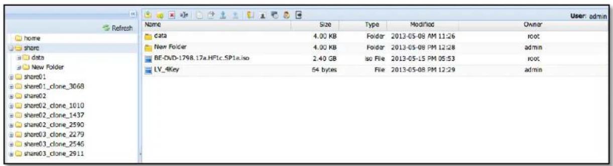
Figure 3.11-1 File Manager
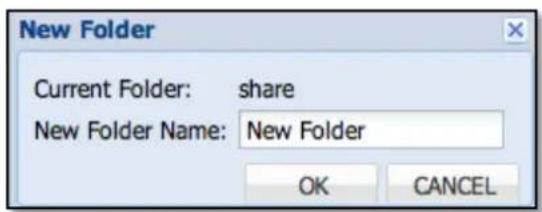
Figure 3.11-2 Create a New Folder
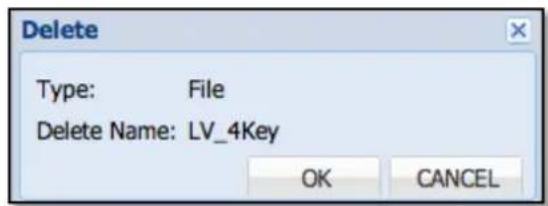
Figure 3.11-3 Delete a File
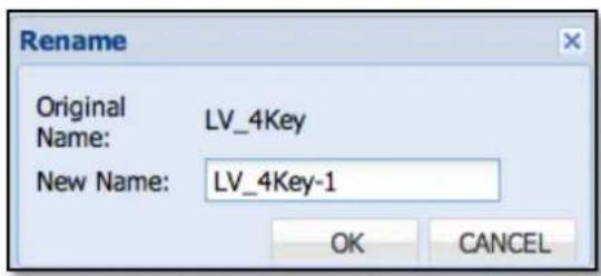
Figure 3.11-4 Rename a File
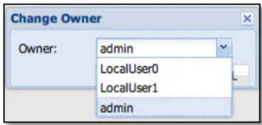
Figure 3.11-5 Change File Owner
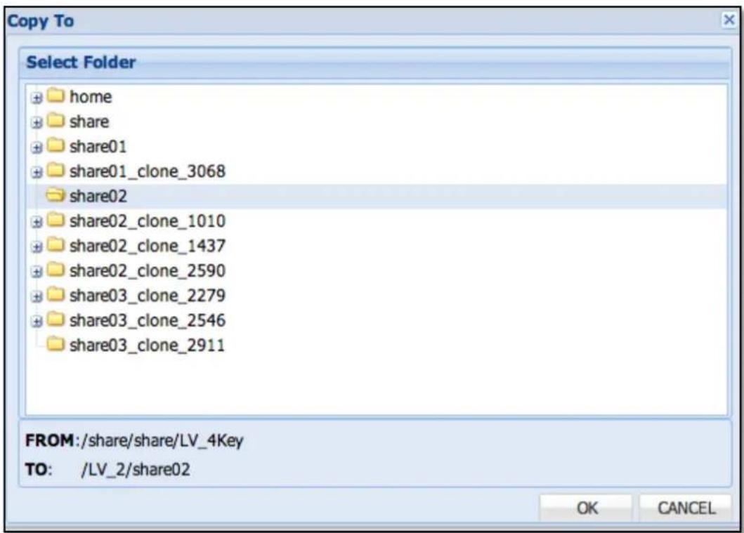
Figure 3.11-6 Copy a File to Selected Destination Folder
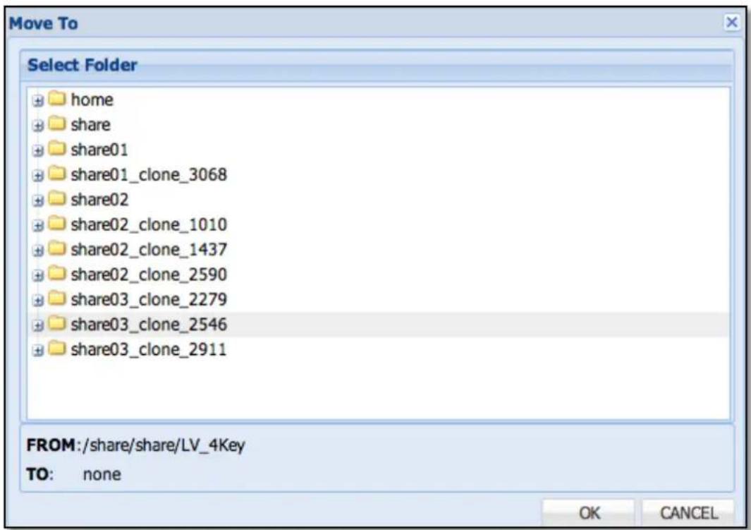
Figure 3.11-7 Move a File to Select Destination Folder
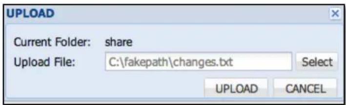
Figure 3.11-8 Upload a File
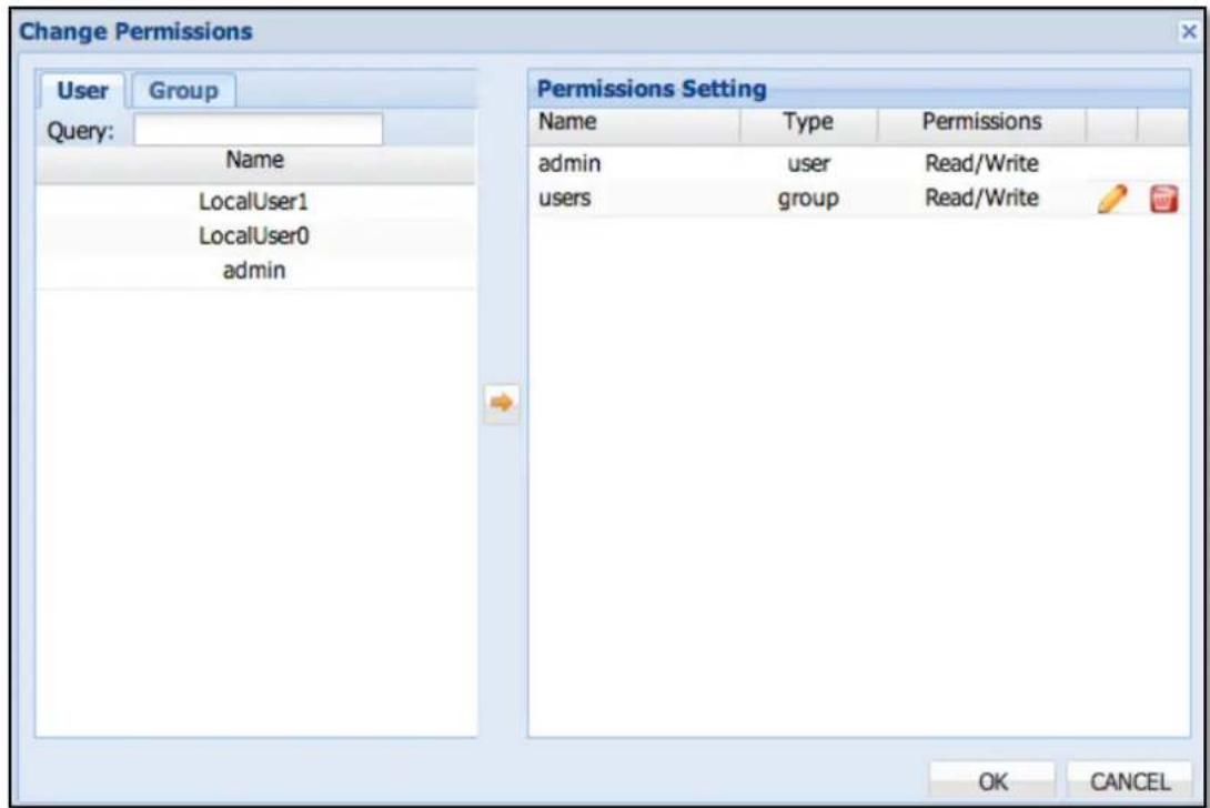
Figure 3.11-9 Change File or Folder Permission
If the NAS user account currently logged on in File Manager is the share owner, he can change file or folder permission (See Figure 3.11-9) under the share.
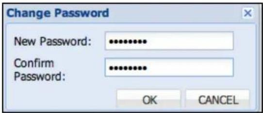
Figure 3.11-10 Change User Password
If NAS users want to change their password, they can logon to File Manager to change their password. This function is only for local NAS user accounts (Figure 3.11-10).
3.12 General Limitation List
Here are some basic limitations list below.
GUI
| Admin login Single Admin | login |
| Shortcut bar icon Max :9 |
System Manager
| NIC ports Max: 8 | |
| Trunk device Max: 4 | |
| Event Email Receiver Max: 8 |
Storage Manager
| Array Number Max: 64 | |
| Volume Group Number Max: 64 | |
| Logical Volume Number Max: 512 | |
| Logical Volume Size Max: 16 TB for ext31000 TB for others | |
| Logical Volumewith Thin Provision Size | Min: 50GBMax: 32 TB or Logical Volume Size x 4 |
iSCSI Target
| Target Number Max: 64 | |
| Connections Max: 32 | |
| Volumes per Target Max: | 256 |
| Initiators ACL per target | Max: 32 |
FC Target
| Target Number Max: 8 | |
| Volumes per Target Max: | 256 |
| WWN ACL per target | Max: 32 |
Share
| Number | Max: 512 |
| ACL per share Max: 64 |
Account
| Number Max: 20000 |
Group
| Number Max: 20000 | |
| Member in group Max: 200 |
Backup
| Plan Number Max: 128 | |
| Snapshots per volume Max: 8 | |
| Snapshot Total Number Max: 256 | |
File Manager
| Max node number in Tree | 10000 |
| Max node number in List | 10000 |
| Upload single file size Max: | 5GB |
LIMITED WARRANTY
This Limited Warranty is provided by Rocstorage, Inc. (hereinafter: Rocstor) for all lines of products.
General Terms
EXCEPT AS EXPRESSLY SET FORTH IN THIS LIMITED WARRANTY, ROCSTOR MAKES NO OTHER WARRANTIES OR CONDITIONS, EXPRESS OR IMPLIED, INCLUDING ANY IMPLIED WARRANTIES OF MERCHANTABILITY AND FITNESS FOR A PARTICULAR PURPOSE. ROCSTOR EXPRESSLY DISCLAIMS ALL WARRANTIES AND CONDITIONS NOT STATED IN THIS LIMITED WARRANTY. ANY IMPLIED WARRANTIES THAT MAY BE IMPOSED BY LAW ARE LIMITED IN DURATION TO THE LIMITED WARRANTY PERIOD. SOME STATES OR COUNTRIES DO NOT ALLOW A LIMITATION ON HOW LONG AN IMPLIED WARRANTY LASTS OR THE EXCLUSION OR LIMITATION OF INCIDENTAL OR CONSEQUENTIAL DAMAGES FOR CONSUMER PRODUCTS. IN SUCH STATES OR COUNTRIES, SOME EXCLUSIONS OR LIMITATIONS OF THIS LIMITED WARRANTY MAY NOT APPLY TO YOU.
This Limited Warranty applies to the Rocstor branded hardware products sold by or leased from Rocstorage, Inc., its worldwide subsidiaries, affiliates, authorized resellers, or country distributors (collectively referred to in this Limited Warranty as "Rocstor") with this Limited Warranty. This Limited Warranty is applicable in all countries and may be enforced in any country where Rocstor or its authorized service providers offer warranty service subject to the terms and conditions set forth in this Limited Warranty. However, warranty service availability and response times may vary from country to country and may also be subject to registration requirements in the country of purchase.
Rocstor warrants that the Rocstor hardware product and all the internal components of the product that you have purchased or leased from Rocstor are free from defects in materials or workmanship under normal use during the Limited Warranty Period. The Limited Warranty Period starts on the date of purchase or lease from Rocstor. Your dated sales or delivery receipt, showing the date of purchase or lease of the product, is your proof of the purchase or lease date. You may be required to provide proof of purchase or lease as a condition of receiving warranty service. You are entitled to warranty service according to the terms and conditions of this document if a repair to your Rocstor branded hardware is required within the Limited Warranty Period. This Limited Warranty extends only to the original purchaser or lessee of this Rocstor branded product and is not transferable to anyone who obtains ownership of the Rocstor branded product from the original purchaser or lessee.
Rocstor products are manufactured using new materials or new and used materials equivalent to new in performance and reliability. Spare parts may be new or equivalent to new. Spare parts are warranted to be free from defects in material or workmanship for thirty (30) days or for the remainder of the Limited Warranty Period of the Rocstor hardware product in which they are installed, whichever is longer.
Rocstor's Obligation under the Limited Warranty
During the Limited Warranty Period, Rocstor will repair or replace the defective component parts or the hardware product. All component parts or hardware products removed under this Limited Warranty become the property of Rocstor. The replacement part or product takes on either the Limited Warranty status of the removed part or product or the thirty (30) day limited warranty of the spare part. In the unlikely event that your Rocstor product has a recurring failure, Rocstor, at its discretion, may elect to provide you with a replacement unit of Rocstor's choosing that is at least equivalent to your Rocstor branded product in hardware performance. Rocstor reserves the right to elect, at its sole discretion, to give you a refund of your purchase price or lease payments (less interest) instead of a replacement. This is your exclusive remedy for defective products. The original Limited Warranty is not extended when the product, or a part of the product, is repaired or replaced during the Limited Warranty period. Rocstor shall not be responsible or liable for backing up any data that is on a drive being returned for service
YOU SHOULD MAKE PERIODIC BACKUP COPIES OF THE DATA STORED ON YOUR HARD DRIVE OR OTHER STORAGE DEVICES AS A PRECAUTION AGAINST POSSIBLE FAILURES, ALTERATION, OR LOSS OF THE DATA. BEFORE RETURNING ANY UNIT FOR SERVICE, BE SURE TO BACK UP DATA AND REMOVE ANY CONFIDENTIAL, PROPRIETARY, OR PERSONAL INFORMATION. ROCSTOR IS NOT RESPONSIBLE FOR DAMAGE TO OR LOSS OF ANY PROGRAMS, DATA, OR REMOVABLE STORAGE MEDIA. ROCSTOR IS NOT RESPONSIBLE FOR THE RESTORATION OR REINSTALLATION OF ANY PROGRAMS OR DATA OTHER THAN SOFTWARE INSTALLED BY ROCSTOR WHEN THE PRODUCT WAS MANUFACTURED.
Rocstor does not warrant that the operation of this product will be uninterrupted or error-free. Rocstor is not responsible for damage that occurs as a result of your failure to follow the instructions that came with the Rocstor branded product.
This Limited Warranty does not apply to expendable parts. This Limited Warranty does not extend to any product from which the serial number has been removed or that has been damaged or rendered defective (a) as a result of accident, misuse, abuse, or other external causes; (b) by operation outside the usage parameters stated in the user documentation that shipped with the product and/or posted on the Rocstor website; (c) by the use of parts not manufactured or sold by Rocstor; (d) as a result of normal wear; or (e) by modification or service by anyone other than (i) Rocstor, (ii) a Rocstor authorized service provider, or (iii) your own installation of end-user replaceable Rocstor or Rocstor approved parts if available for your product in the servicing country.
These terms and conditions constitute the complete and exclusive limited warranty agreement between Rocstor and you regarding the Rocstor branded product you have purchased or leased. These terms and conditions supersede any prior agreements or representations including representations made in Rocstor sales literature or advice given to you by Rocstor or an agent or employee of Rocstor-that may have been made in connection with your purchase or lease of the Rocstor branded product. No change to the conditions of this Limited Warranty is valid unless it is made in writing and signed by an authorized representative of Rocstor.
Buyer's Obligation under the Warranty
The person requesting coverage under this warranty shall prove that he or she is the original purchaser and declares that the product has not been sold, leased, bartered or otherwise changed possession. The purchaser shall frequently backup the Enteroc Storage hard drive and backup the data immediately prior to returning the drive for warranty service.
The buyer must notify Rocstor and show proof of notification, through any reasonable means of communication. See Full Street address email address and toll free phone numbers below or updated contact information are available on Rocstor.com website. The notification shall identify any defect, malfunction, or nonconformity promptly upon discovery. Rocstor will acknowledge receipt of the communication and issue a Return Merchandise Authorization (RMA) code. The buyer is obligated to securely and safely package(s) the product, preferably in the original packing materials, WITH THE RMA number, and deliver it together with a copy of the original purchase receipt and a description of the problem to the Rocstor home office. Buyer is responsible for the product until it is received by Rocstor. It is recommended that the product be insured during transportation by the sender. You must prepay any shipping charges, taxes, or duties associated with transportation of the product. In addition, you are responsible for insuring any product shipped or returned for service. You assume risk of loss during shipping.
Limitation of damages (Liability)
IF YOUR ROCSTOR BRANDED HARDWARE PRODUCT FAILS TO WORK AS WARRANTED ABOVE, THE ORIGINAL PURCHASER'S SOLE AND EXCLUSIVE REMEDY SHALL BE REPAIR OR REPLACEMENT. ROCSTOR'S MAXIMUM LIABILITY UNDER THIS LIMITED WARRANTY IS EXPRESSLY LIMITED TO THE LESSER OF THE PRICE YOU HAVE PAID FOR THE PRODUCT OR THE COST OF REPAIR OR REPLACEMENT OF ANY ROCSTOR HARDWARE COMPONENTS THAT
MALFUNCTION IN CONDITIONS OF NORMAL USE. ROCSTOR IS NOT LIABLE FOR ANY DAMAGE TO ANY OTHER PRODUCT CONNECTED TO A ROCSTOR PRODUCT.
Limitation on Consequential Damages
ROCSTOR IS NOT LIABLE FOR ANY DAMAGES CAUSED BY THE PRODUCT OR THE FAILURE OF THE PRODUCT TO PERFORM, INCLUDING ANY LOST PROFITS OR SAVINGS OR SPECIAL, INCIDENTAL OR CONSEQUENTIAL DAMAGES. ROCSTOR IS NOT LIABLE FOR ANY CLAIM MADE BY A THIRD PARTY OR MADE BY YOU FOR A THIRD PARTY. THIS LIMITATION OF LIABILITY ALSO APPLIES WHETHER DAMAGES ARE SOUGHT OR A CLAIM IS MADE UNDER THIS LIMITED WARRANTY OR AS A TORT CLAIM (INCLUDING NEGLIGENCE AND STRICT PRODUCT LIABILITY), A CONTRACT CLAIM OR ANY OTHER CLAIM. THIS LIMITATION OF LIABILITY CANNOT BE WAIVED OR AMENDED BY ANY PERSON. THIS LIMITATION OF LIABILITY WILL BE EFFECTIVE EVEN IF YOU HAVE ADVISED ROCSTOR OR AN AUTHORIZED REPRESENTATIVE OF ROCSTOR OF THE POSSIBILITY OF ANY SUCH DAMAGES.
THIS LIMITED WARRANTY GIVES YOU SPECIFIC LEGAL RIGHTS. YOU MAY ALSO HAVE OTHER RIGHTS THAT MAY VARY FROM STATE TO STATE OR FROM COUNTRY TO COUNTRY. YOU ARE ADVISED TO CONSULT APPLICABLE STATE OR COUNTRY LAWS FOR A FULL DETERMINATION OF YOUR RIGHTS.
Disclaimer
We accept no liability for any loss of data, damages and the inability of Rocstor products to work with any third party equipment. Nor can Rocstor accept any liability or responsibility for software or third party hardware products.
Limited Warranty Period
The limited warranty period for Enteroc Storage is Three (3) Years Parts and Labor. This Limited Warranty extends only to the original purchaser or lessee of this Rocstor branded product and is not transferable to anyone who obtains ownership of the Rocstor branded product from the original purchaser or lessee.
Types of Limited Warranty Service
Your Rocstor Limited Warranty consists of repair or replacement of defective parts, including hard drives identified by Rocstor Support Organization as “pre-failure.”
Carry-in Limited Warranty Service Available Monday - Friday
Under the terms of carry-in service, you may be required to deliver your Rocstor product to the Rocstor Service Center or an authorized service location for warranty repair. You must prepay any shipping charges, taxes or duties associated with transportation of the product. In addition, you are responsible for insuring any product shipped or returned for service. You assume risk of loss during shipping.
YOU SHOULD MAKE PERIODIC BACKUP COPIES OF THE DATA STORED ON YOUR HARD DRIVE OR OTHER STORAGE DEVICES AS A PRECAUTION AGAINST POSSIBLE FAILURES, ALTERATION OR LOSS OF THE DATA. BEFORE RETURNING ANY UNIT FOR SERVICE, BE SURE TO BACK UP DATA AND REMOVE ANY CONFIDENTIAL, PROPRIETARY OR PERSONAL INFORMATION. ROCSTORAGE IS NOT RESPONSIBLE FOR DAMAGE TO OR LOSS OF ANY PROGRAMS, DATA OR REMOVABLE STORAGE MEDIA. ROCSTORAGE IS NOT RESPONSIBLE FOR THE RESTORATION OR REINSTALLATION OF ANY PROGRAMS OR DATA OTHER THAN SOFTWARE INSTALLED BY ROCSTORAGE WHEN THE PRODUCT WAS MANUFACTURED.
Rocstorage shall not be responsible or liable for backing up any data that is on a drive being returned for service. Expect that all data on the drive will be destroyed and not retrievable when returned for warranty service.
Rocstor Replaceable Parts Program
Where available, the Rocstor Replaceable Parts program ships approved replacement parts directly to you to fulfill your warranty. This will save considerable repair time. After you call the Rocstor Technical Support Center at 818.727.7000 a replaceable part can be sent directly to you. Once the part arrives, call the Rocstor Technical Support Center. A technician will assist you over the phone to ensure that the installation is quick and easy.
Service Upgrades
Rocstor offers extra coverage for your product. For information on service upgrades, visit www.rocstor.com. Service upgrades purchased in one country are not transferable to another country.
Capacity Disclaimer
Actual accessible hard drive capacity will indicate up to 10% lower than stated under different Operating Systems and formatting.
The storage volume is measured in total bytes before formatting. References to round numbers of gigabytes or terabytes are an approximation only. For example, a disk drive labeled as having 500GB (Gigabytes) has space for approximately 500,000,000 bytes before formatting. After formatting, the drive capacity is reduced by about 5% to 10% depending on the operating system and formatting used or "1GB = 1,000,000,000 bytes.
Options and Software
The Limited Warranty terms and conditions for Rocstor options are as indicated in the Limited Warranty applicable to Rocstor options. ROCSTOR DOES NOT WARRANTY SOFTWARE PRODUCTS, INCLUDING ANY SOFTWARE PRODUCTS OR THE OPERATING SYSTEM PREINSTALLED BY ROCSTOR. Rocstor's only obligations with respect to software distributed by Rocstor under the Rocstor brand name are set forth in the applicable end-user license or program license agreement. Non-Rocstor hardware and software products are provided "AS IS" and without any Warranty. However, non-Rocstor manufacturers, suppliers or publishers may provide their own warranties directly to you.
The data stored in Rocstor and Rocsecure storage product lines are not guaranteed by Rocstor (or the hard disk manufacturer.) We are not responsible for any loss of data. Always back up data regularly
TECHNICAL SUPPORT
Software Technical Support
Software technical support is defined as assistance with questions and issues about the software that was either preinstalled by Rocstor on the Rocstor branded product or that was included with the Rocstor branded product at the time of your purchase or lease of the product. Technical support for software is available for the first ninety (90) days from date of product purchase or lease. Your dated sales or delivery receipt, showing the date of purchase or lease of the product, is your proof of the purchase or lease date. You may be required to provide proof of purchase or lease as a condition of receiving software technical support. After the first ninety (90) days, technical support for software that was either preinstalled by Rocstor on the Rocstor branded product or included with the Rocstor branded product at the time of your purchase or lease of the product is available for a fee.
WARNING: The individual user should take care to determine prior to use whether this device is suitable, adequate or safe for the use intended. Since individual applications are subject to great variation, the manufacturer
"Rocstor" makes no representation or warranty as to the suitability or fitness of these devices for any specific application.
Technical Support
All Rocstor hard drives are backed by free telephone technical support for three (3) years from the date of purchase. Please register your product with Rocstor. To register, fill in the Limited Warranty Registration form in the Support tab at www.rocstor.com.
Free telephone technical support is available weekdays from 9 AM until 6 PM Pacific Standard Time. Customers in the United States and Canada can call toll-free: (818) 727-7000; all others must call (818) 727-7000.
When calling for support, please have the product's serial number (printed on the label on the bottom of the drive) and system hardware information available.
Trademarks Acknowledgements
© 2017, Rocstorage, Inc; acknowledges the following trademarks for company names or products mentioned within the Rocstor site, portal pages and articles/text/manuals:
Rocstor, Rocsecure and Rocpower are registered trademarks of Rocstorage, Inc. Amphibious, Rocport, Rocbit, Rocsafe, Enteroc are the trademarks of Rocstorage, Inc. "store your future", "secure your future" and "power your future" are the slogan marks of Rocstorage, Inc.
Apple, the Apple logo, Mac, Power Macintosh, FireWire, and Mac Pro, Leopard, Snow Leopard ... are trademarks of Apple Computer, Inc. in the United States and other countries.
Microsoft, MS-DOS, Windows CE, Windows NT, Windows 98, Soft Windows, Vista, Windows 7 ... are registered trademarks of Microsoft Corporation in the United States and other countries.
Intel, Itanium, Pentium XXX, Celeron, and Xeon MMX ... are registered U.S. trademarks of Intel Corporation or its subsidiaries in the United States and other countries.
This product is (may also be) integrated with SATA hard drives from the following manufactures: Seagate, Samsung, Western Digital, Hitachi, Toshiba, Fujitsu ...
All other names are trademarks of their respective companies.
Rocstor wishes to acknowledge the use of tables, charts, graphs and texts from the Wikipedia website.
© 2000 - 2019
Copyrights
© 2019 Rocstorage, Inc. This Manual is protected by United States copyright law and may not be reproduced, distributed, transmitted, displayed, published or broadcast without the prior written permission of Rocstorage, Inc. You may not alter or remove any trademark, copyright or other notice from copies of this Manual.

natural_image
National flag of the United States (no text or symbols beyond stars)Designed, integrated and assembled by Rocstor in the U.S.A. using domestic and/or foreign components.
Rocstor is a California Company; U.S.A.
Contact Information
Corporate Headquarters
12979 Arroyo Street, 2nd Floor
San Fernando, California 91340
U.S.A. Office: +1 (818) 727-7000
Email: info@Rocstor.com
Technical Support / RMA
Tel: (818) 727-7000 (USA and Canada)
Tel: +1 (818) 727-7000 (Domestic and
Hours: 9:00 am - 5:00 pm PST
Mon - Fri (excluding holidays)
Email: support@Rocstor.com
Sales Info
Hours: 8:00 am - 5:00 pm PST
Mon - Fri (excluding holidays)
Email: sales@Rocstor.com
Corporate, Government and Academic Customers
Our Corporate Sales Team's goal is to help our U.S.A. and Canadian customers find a storage solution that best serves their needs. We will help you determine your best purchasing options. For more information please contact the appropriate department below or call us at +1 (888) 877-7716
General sales information: sales@Rocstor.com
Corporate sales information: corporate_sales@Rocstor.com
Educational sales information: academic_sales@Rocstor.com
Federal, State & Local government sales information: government_sales@Rocstor.com

- Configuration Guide
- Table of Contents
- Preface 4
- Chapter 1 Introduction ....5
- Chapter 2 Getting Started With proNAS 3.6 9
- Connecting to the NAS Share Folder via Network 15
- Chapter 3 System Management....17
- System Manager 24
- Storage Manager....43
- Service Manger....73
- Account Manager 85
- Backup Manager 97
- Attached Device Manager 126
- Plug-in Manager.... 130
- File Manager 148
- General Limitation List 152
- Preface
- About this manual
- NOTES:
- IMPORTANT!
- WARNING!
- CAUTION:
- Copyright
- Trademarks
- Changes
- Chapter 1 Introduction
- Key Features
- Technical Specifications
- Chapter 2 Getting Started With proNAS 3.6
- Prepare to Setup NAS
- NOTE: Compatible List of Hard Drive Models
- Login NAS Management Webpage by Using Web Browser
- NOTE:
- Setup and Installation
- Quick Setup
- Network
- Array
- Logical Volume
- Service
- Manually Initializing the NAS Step by Step
- Connecting to the NAS Share Folder via Network
- Windows Users (SMB/CIFS)
- Mac OS Users (SMB or AFP)
- Linux Users (NFS)
- Example:
- Chapter 3 System Management
- Basic Layout of NAS Management GUI
- Part 1. Top Menu:
- Part 2. Left Tree:
- Top Shortcut Bar
- Modifying Shortcut Functions in the Shortcut Bar
- To Add:
- To Remove:
- System Monitoring
- System Information
- Resource Monitor
- System Log
- System Manager
- General
- Date/Time
- Network
- Adapter:
- Edit:
- Trunking:
- Default Gateway:
- DNS:
- Hosts Table:
- The following lines are desirable for IPv6 capable hosts
- LmHosts Table:
- IPv6:
- Security:
- Routing Table:
- UPS
- Event
- Email setting:
- SNMP Trap Receiver :
- Power
- Description of Options in Resetting to Factory Default:
- Upgrade
- Tools
- Schedule Manager
- Storage Manager
- RAID / Array Manager
- Functions on Array Manager (left pane):
- Array List:
- Volume Group Manager
- Volume Allocation options:
- Expanding Logical Volume Capacity:
- Volume Encryption:
- Automatic Mount After Boot:
- SSD cache: (support by zfs)
- iSCSI Manager
- FC Manager
- Enable or Disable FC Target Port:
- Add FC Volume:
- Block Size:
- Add FC WWN Initiator:
- Permission:
- Remove WWN Initiator:
- Remove FC Target Volume:
- Share Manager
- Add Account Permission:
- Add Group Permission:
- Add IP Permission:
- Edit Share Folder:
- Share Protocol:
- CIFS
- NFS
- Apple Talk
- Rsync
- Edit Access Right:
- Delete Share Folders:
- Service Manger
- Samba service
- NFS service
- AFP service
- FTP service
- WebDAV service
- TFTP service
- Rsync service
- SNMP service
- DHCP service
- SSH service
- Telnet service
- File Manager
- Account Manager
- Account
- Format of each Account Entry:
- Group
- Directory Service
- Enable ADS Authentication:
- Automatic detect Domain IP:
- Synchronize time to ADS:
- Auto Detect Enctypes:
- Enable NIS Authentication:
- Enable LDAP Authentication:
- Backup Manager
- Data Backup
- Destination Description:
- Restore:
- Back Plan Summary:
- Data Copy
- Replication Backup
- Extending Logical Volume Size under Replication Backup
- Snapshot Backup
- Volume Clone
- Rsync Backup
- Local Share Folder
- Remote Share Folder
- System Configuration
- Amazon S3
- Get Amazon S3 account
- Attached Device Manager
- Physical Device
- ISO Mount
- iSCSI Initiator
- Button in Host list
- Plug-in Manager
- How To install
- Register:
- NAS HA
- What's NAS HA?
- NAS HA Setup Steps:
- Configure NAS Host Names
- Configure Network Settings
- Configure Logical Volumes and Share Folders
- Install NAS HA Plug-In
- Steps:
- Setup NAS HA and Start HA Service
- HA Cluster Quick Setup
- HA Fail-Over
- Fail-Over Scenario
- Testing HA Fail-Over
- File Manager
- General Limitation List
- LIMITED WARRANTY
- General Terms
- Rocstor's Obligation under the Limited Warranty
- Buyer's Obligation under the Warranty
- Limitation of damages (Liability)
- Limitation on Consequential Damages
- Disclaimer
- Limited Warranty Period
- Types of Limited Warranty Service
- Carry-in Limited Warranty Service Available Monday - Friday
- Rocstor Replaceable Parts Program
- Service Upgrades
- Capacity Disclaimer
- Options and Software
- TECHNICAL SUPPORT
- Software Technical Support
- Trademarks Acknowledgements
- Copyrights
- Contact Information
- Corporate Headquarters
- Technical Support / RMA
- Sales Info
- Corporate, Government and Academic Customers
Brand : Rocstor
Model : Enteroc N1822
Category : Server