Optera IMM12036-B1I - Security Camera Pelco - Free user manual and instructions
Find the device manual for free Optera IMM12036-B1I Pelco in PDF.


| Product Type | Security Camera |
| Brand | Pelco |
| Model | Optera IMM12036-B1I |
| Field of View | Panoramic (180°, 270°, or 360° depending on model) |
| Resolution | Configurable, up to full HD |
| Compression | H.264, H.265, MJPEG |
| Power Source | Listed Power Adapter or DC L.P.S. supply |
| Network | Ethernet 10/100, IPv4/IPv6, DHCP/static |
| Storage | MicroSD card (local recording, snapshots) |
| Audio | Built-in microphone or line-in |
| Analytics | Abandoned object, adaptive motion, camera sabotage, directional motion, loitering, object counting, object removal, stopped vehicle, 2-camera tracking |
| Event Handling | Email, FTP upload, relay output, local JPEG, event stream |
| Security | TLS, SSH, 802.1x, firewall, user roles (admin, manager, operator, viewer) |
| Mounting | Ceiling or wall mount (indoor/outdoor) |
| Compatibility | Pelco VMS, ONVIF, Pelco Camera Link with Enhanced Series PTZ |
| Warranty | See www.pelco.com/warranty |
Frequently Asked Questions - Optera IMM12036-B1I Pelco
User questions about Optera IMM12036-B1I Pelco
0 question about this device. Answer the ones you know or ask your own.
Ask a new question about this device
Download the instructions for your Security Camera in PDF format for free! Find your manual Optera IMM12036-B1I - Pelco and take your electronic device back in hand. On this page are published all the documents necessary for the use of your device. Optera IMM12036-B1I by Pelco.
USER MANUAL Optera IMM12036-B1I Pelco
natural_image
Close-up of a white surveillance camera with multiple circular lenses and a dome-shaped head (no visible text or symbols)Document number: C2284M
Publication date: 08/20
Table of Contents
Important Notices.5....
Regulatory Notices.5..... Radio and Television Interference.5....
Warranty Statement 5
Legal Notice.5
Audio Notice.5....
Video Quality Caution 5. Frame Rate Notice Regarding User Selected Options 5.
Open Source Software 6
Power Source 6
Accessing the Camera....7
Accessing Camera Settings.... 7
Accessing the Live Video Page 8
Live Video Controls 8
Using the System Menu....9
Changing the Camera Name....9
Enabling and Disabling LEDs....9
Optera Compatibility Mode 9
Tiled Mode (Assembling Panoramic Scenes) 10 Adjusting the Image Angle 11
Configuring Time Settings.... 11
Generating a System Log.... 11
Restarting the Camera.... 12
Restoring All Camera Defaults 12
Backing Up and Restoring Settings.... 12
Back Up Camera Settings....12 Restore Camera Settings from a Backup....12
Firmware 12
Configuring OSDi Overlays 13
Snapshot Viewer 13
Onboard Storage Management 13
Using the Network & Security Menu 14
Changing General Network Settings.... 14
Understanding General Network Settings 14
Network Hostname 14
Port Settings 14
Link Settings 14
Managing Network and Security.... 15
User Management 15
Configuring Users.16
Optera™ Operations Manual
Setting Security/Authentication 16
Configuring TLS 16
Enabling SSH 17
Configuring Traffic Shaping 17
Configuring 802.1x Security 18
Configuring SNMP 18
Configuring the SMTP Server 19
Configuring SNMP V2c.19
Configuring SNMP V3 19
Firewall Configuration 19
Configuring Firewall Settings 19
Using the Imaging Menu 20
Configuring General Imaging Settings 20
Configuring Exposure Settings 20
Setting White Balance 21
Using the Window Blanking Feature 21
Realigning the Camera Sensors 22
Manually Aligning the Camera Sensors 22
Using the A/V Streams Menu 24
Configuring a Custom Video Configuration 24
Configuring Video Settings 24
Configuring Audio 25
Managing Local Recording 26
Configuring Local Recording 26
Managing RTP Settings 26
Setting Static Multicast Addresses 27
Setting the Maximum Transfer Unit Size (TCP/IP) 27
Smart Compression 27
Configuring Smart Compression 27
Using the Events Menu 29
Event Stream 29
Configuring Sources 29
Configuring an Alarm Event Source 29
Configuring an Analytic Event Source 30
Configuring a System Event Source 30
Configuring a Timer Event Source 30
Deleting an Event Source 30
Configuring Handlers 31
Configuring an Event Handler: Send Email 31
Configuring an Event Handler: Write JPEG to SD.Card 31
Configuring an Event Handler: Upload JPEG to FTP Server 32
Configuring an Event Handler: Open/Close Relay 32
Deleting an Event Handler 33
Optera™ Operations Manual
Analytic Configuration.33.
Configuring Profile Settings .33.
Applying Select Behaviors.34
Configuring an Analytic Profile 38
Running Profiles.39
Setting Up and Operating Pelco Camera Link 39
Important Notices
Regulatory Notices
This device complies with Part 15 of FGE RulesOperation is subject to the following two conditions: (1) this device may not cause harmful interference, and (2) this device must accept any interference received, including interference that may cause undesired operation.
Radio and Television Interference
This equipment has been tested and found to comply with the limits of a Class A digital device, pursuant to Part 15 of the FCC rules. These limits are designed to provide reasonable protection against harmful interference when the equipment is operated in a commercial environment. This equipment generates, uses, and can radiate radio frequency energy and, if not installed and used in accordance with the instruction manual, may cause harmful interference to radio communications. Operation of this equipment in a residential area is likely to cause harmful interference in which case the user will be required to correct the interference at his own expense.
Changes and modifications not expressly approved by the manufacturer or registrant of this equipment can void your authority to operate this equipment under Federal Communications Commission's rules.
CAN ICES-3 (A)/NMB-3(A)
Warranty Statement
For information about Pelco's product warranty and thereto related information, refer to www.pelco.com/warranty.
Legal Notice
SOME PELCO EQUIPMENT CONTAINS, AND THE SOFTWARE ENABLES, AUDIO/VISUAL AND RECORDING CAPABILITIES, THE IMPROPER USE OF WHICH MAY SUBJECT YOU TO CIVIL AND CRIMINAL PENALTIES. APPLICABLE LAWS REGARDING THE USE OF SUCH CAPABILITIES VARY BETWEEN JURISDICTIONS AND MAY REQUIRE, AMONG OTHER THINGS, EXPRESS WRITTEN CONSENT FROM RECORDED SUBJECTS. YOU ARE SOLELY RESPONSIBLE FOR INSURING STRICT COMPLIANCE WITH SUCH LAWS AND FOR STRICT ADHERENCE TO ANY/ALL RIGHTS OF PRIVACY AND PERSONALTY. USE OF THIS EQUIPMENT AND/OR SOFTWARE FOR ILLEGAL SURVEILLANCE OR MONITORING SHALL BE DEEMED UNAUTHORIZED USE IN VIOLATION OF THE END USER SOFTWARE AGREEMENT AND RESULT IN THE IMMEDIATE TERMINATION OF YOUR LICENSE RIGHTS THEREUNDER.
Audio Notice
Improper use of audio/visual recording equipment may subject you to civil and criminal penalties. Applicable laws regarding the use of such capabilities vary between jurisdictions and may require, among other things, express written consent from the recorded subjects. You are solely responsible for insuring strict compliance with such laws and for strict adherence to any/all rights of privacy and personality.
Video Quality Caution
Frame Rate Notice Regarding User Selected Options
Pelco systems are capable of providing high quality video for both live viewing and playback. However, the systems can be used in lower quality modes, which can degrade picture quality, to allow for a slower rate of data transfer and to reduce the amount of video data stored. The picture quality can be degraded by either
lowering the resolution, reducing the picture rate, or both. A picture degraded by having a reduced resolution may result in an image that is less clear or even indiscernible. A picture degraded by reducing the picture rate has fewer frames per second, which can result in images that appear to jump or move more quickly than normal during playback. Lower frame rates may result in a key event not being recorded by the system. Judgment as to the suitability of the products for users' purposes is solely the users' responsibility. Users shall determine the suitability of the products for their own intended application, picture rate and picture quality. In the event users intend to use the video for evidentiary purposes in a judicial proceeding or otherwise, users should consult with their attorney regarding any particular requirements for such use.
Open Source Software
This product includes certain open source or other software originated from third parties that is subject to the GNU General Public License (GPL), GNU Library/Lesser General Public License (LGPL) and different and/or additional copyright licenses, disclaimers, and notices. The exact terms of GPL, LGPL, and some other licenses are provided to you with this product. Please refer to the exact terms of the GPL and LGPL a http://www.fsf.org (Free Software Foundation) or http://www.opensource.org (Open Source Initiative) regarding your rights under said license. You may obtain a complete corresponding machine-readable copy of the source code of such software under the GPL or LGPL by sending your request to digitalsupport@pelco.com; the subject line should read Source Code Request. You will then receive an email with a link for you to download the source code. This offer is valid for a period of three (3) years from the date of the distribution of this product by Pelco.
Power Source
This product is intended to be supplied by a Listed Power Adapter or DC power source marked “L.P.S.” (or “Limited Power Source”), rated according to the camera specification document. If you need further assistance with purchasing the power source, please contact Pelco, Inc. for further information.
Accessing the Camera

Note: For security purposes, it is required that you create a user account when you access the camera for the first time. In its out-of-the-box configuration, the camera has no user name and password assigned. In this state the camera does not allow for video to stream or configurations to change. It is required that you set an administrative user name and password at this time. Creation of an administrative user changes the state of the camera to its “operational mode,” where credentials must be provided in order to view live video or change its configuration. This first user configuration can also be done in VxToolbox software.
There is no provision for recovering a forgotten administrator user name or password. The camera can be restored to its out-of-the-box, no user name and password configuration by powering down, depressing the Factory Defaults button, and holding the button down for at least four seconds while powering the camera back up.
Once the camera is powered back up the user will be prompted to create a username and password.
The recommended browsers for your camera are Mozilla® Firefox®, Google Chrome™, or Microsoft™ Edge™ for Microsoft® Windows® operating systems; and Firefox for Mac® operating systems. For supported browser versions, refer to the Specification Sheet for your product.
- Open a web browser.
- If a user name and password exist, a log in dialog box appears. Otherwise a user creation dialog box appears, and the user will be required to create an administrative user to proceed.
Accessing Camera Settings
- Log in.
- Click Settings.
- Click the setting you want to change. Place your mouse pointer over any menu on the page to reveal submenus.
Accessing the Live Video Page
The live video page provides access to video streams and, where applicable, to PTZ controls. The camera defaults to the live video page, but can be accessed by clicking Live at the upper right corner of the window.
Live Video Controls
Viewable controls are based on camera model and user permissions.
 | Open Stream in New Window: Opens the video stream in an independent window. |
 | Take a Snapshot: Captures a still image from the video stream and saves it as a JPEG file. |
Using the System Menu
The System menu contains general system time settings, and on screen display settings. It also provides access to basic system information, and the backup, restore, and restart functions. Options may vary depending on your camera model.
From the System menu, you can also access snapshots generated by event handlers.
Changing the Camera Name
Providing a user-friendly name might help you and other users identify the camera on the network, and within other applications. The camera name is the name that appears both in the Web interface and within other applications that can find the device.
- Select General Settings from the System menu.
- Provide a user-friendly name in the Device Name box (between 2 and 63 alphanumeric characters).
- Click Save.
Enabling and Disabling LEDs
You can turn your camera's LEDs on or off. By default, your camera's LEDs are on. LED settings do not affect your camera's network status and activity LEDs.
- Select General Settings from the System menu.
- Select On or Off beside Enable LEDs.
- Click Save.
Optera Compatibility Mode
Optera Compatibility Mode determines the type of stream(s) the camera sends to your Video Management System, recorders, and clients. You should set the compatibility mode based on the panomersive integration with your VMS. Check with your integrator to determine the panomersive implementation within your VMS or client.
- Panomersive mode is for classic, typical panomersive/Optera integrations including VideoXpert.
The camera produces multiple streams representing the cube faces used by the Panomersive Toolkit; the toolkit then assembles the streams as a single view at the VMS or client. Use this mode for typical panomersive integrations, especially in VMS environments representing Optera as multiple physical cameras. - Tiled mode is for VMSes or clients that do not have a panomersive integration to dewarp and assemble Optera streams. In this mode, the camera outputs “tiled” streams that the user can assemble in a client to resemble a panorama. (For example, a 180 camera would output 3 “tiled” streams; the user would place the streams next to each other in order at the client, producing the semblance of a panorama across the three tiles or cells. You cannot use virtual PTZ controls when in tiled mode.

Note: Switching to or from tiled mode clears all analytics and window-blanking settings.
- Panomersive Uni-stream mode is for panomersive implementations that recognize Optera as a single camera or stream. The camera outputs a single video stream that the Panomersive Toolkit integration dewarps and allows users to access. The dimensions of the uni-stream are larger than allowed by h.264 specifications; this may result in issues with decoders expecting streams that strictly comply with dimensions defined by the h.264 specification.
To set or change the Optera compatibility mode:
- Go to the System page.
- Select your Optera Compatibility Mode.
- Click Save .
Tiled Mode (Assembling Panoramic Scenes)
Tiled Mode produces multiple "flat" streams, each representing a fraction of the camera's panoramic view.
Each stream appears as a video source or “camera” within your client or VMS. You can either assemble the video sources to represent a panorama, or you can watch the individual streams as necessary to get a view from the camera.
Endura and integrations using the Pelco API to discover cameras will recognize Optera streams/tiles in the following order:
- Mosaic Stream (full, low-quality panorama)
- Right Stream
- Front Stream (center)
- Left Stream
- Bottom stream (for 270 models only)
If a VMS does not use the Pelco API to discover Optera cameras, then the sequence by which the VMSes connect to Optera tiled streams may not necessarily be the order in which streams are numbered by the camera. For example, stream 2 as determined by the VMS might not always represent the left-most stream in the panorama. If this is the case, you might need to rearrange your Optera camera streams in adjacent cells so that they appear in order. If your VMS or client allows you to assign friendly names to the streams, you might want to rename the streams to better represent their orientation; you cannot rename or order the streams through the Optera interface or API.

Note: For best results in an Endura environment (using a WS5080 or better), use a 2x2 layout to display the full panorama of Optera tiles side-by-side. You must be running a version of the Workstation software later than 2.7.0 to use a 3x2 layout, allowing you to piece together a full 180°/360° tiled panorama.
Table 1: Optera Tiled Panoramas
| Optera | Camera | Streams | Expected | Tile | Layout in | VMS | (for Endura/Pelco API Str |
| 180° | 4 | 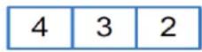 | |||||
| 270° | 5 | 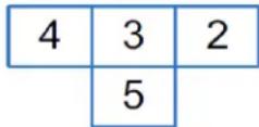 | |||||
| 360° | 4 | 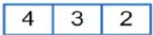 |
Hardware Requirements for Tiled Mode
Optera's tiled mode is resource intensive. Depending on your hardware, you may not be able to display all tiles belong to a panorama at one time. Tiled mode was tested against Endura WS5070 and WS5080
products; use the following guidelines to determine how many tiled streams you can display simultaneously.

Note: Attempting to exceed the limitations of your hardware may cause poor performance or dropped streams.
Table 2: Tiled Stream Hardware Requirements
| 1 tile (1x1 layout - WS5070) 4 tiles (2x2/3x3 layout - WS5080) | ||
| Processor | Intel® Xeon® X3220 Processor Intel® | Xeon® E3-1275 v3 |
| Memory | 2 GB 8 GB DDR3 ECC | |
Adjusting the Image Angle
The Corridor Mode and Install Angle settings enable a VMS to display views optimally. These settings are only available for 180° models.
Corridor Mode
Corridor Mode directs a VMS or client to rotate the camera image, providing a natural immersive view of a portrait scene. Use Corridor Mode when monitoring corridors, hallways, shopping aisles, railway platforms, and other scenes in which the area of interest is tall rather than wide.
Click On to rotate the image to portrait mode. Click Off to return the camera image to the standard landscape mode.
Install Angle
The Install Angle setting directs a VMS or client to tilt the camera image to provide a more natural immersive view for scenes that are not strictly horizontal, similar to parking lots.
Drag the slider to set the install angle, or enter the specific image angle value.
Example: If the camera is mounted with the lens plane horizontal, the Install Angle setting is 0°. Change the Install Angle to -30° to tilt the lens downward when viewing a parking lot.
Configuring Time Settings
You can set your camera to discover a network time server (NTP) automatically, manually provide the address of your network time server, or select no time server.
-
Go to System > General Settings.
-
Select your time server setting:
-
Auto: Allows your camera to discover and synchronize with your network time server (over IPv4 or IPv6).
-
Manual: Requires you to provide the address of your network time server.
• None: Camera date format defaults to mm/dd/1970. -
Select the Time Zone.
-
Select Save.
Generating a System Log
If technical difficulties occur, a system log might help Pelco Product Support troubleshoot problems with your camera. You can contact Pelco Product Support at 1-800-289-9100 (USA and Canada) or +1-559-292-
1981 (international).
- Select General Settings from the System menu.
- select Generate System Log.
- Select the location in which to save the log file.
- Click Save.
Restarting the Camera
If you are recording video from your camera, restarting the camera will cause a gap in video recording. It is important that you schedule maintenance before restarting the camera.
- Select General Settings from the System menu.
- select Reboot Camera.
Restoring All Camera Defaults
Restoring default settings will overwrite all of your existing settings with device defaults.

Note: If your device has been configured with a static IP address, restoring factory defaults will remove the static IP and set the device to obtain an address over DHCP.
- Select General Settings from the System menu.
- select Restore All Camera Defaults.
Backing Up and Restoring Settings
You can create a backup file of your device's configuration so that if you accidentally change a setting or need to recover from a factory reset, you can revert back to this saved configuration. Camera backup files are stored in bin format.

Note: The restore feature is not intended to automatically configure multiple devices or to recover settings following a firmware upgrade.
Back Up Camera Settings
- Got to System > Backup and Restore.
- Click Generate Backup File.
- Click Download Now, and then specify the directory in which to save your backup file.
Restore Camera Settings from a Backup
- Go to System > Backup and Restore.
- Click Browse, click the desired backup file, and then click Open.
- Click Upload and Restore; to restart the camera and restore the camera settings.
Firmware
The Firmware page includes read-only fields for the firmware version, hardware version, model number, and serial number of the camera. This information is typically required by Pelco Product Support for troubleshooting purposes.
There is also a firmware update section that allows you to upgrade the firmware on your camera.
Configuring OSDi Overlays
The OSDi (Intelligent On Screen Display) feature allows the camera to show pertinent information as an overlay within the field of view. Depending on your camera and model, you may be able to define up to three overlay rules. You can also determine the position of each overlay within the scene.
If using PTZ Preset or Zone overlays, the overlay will use the name of the zone or PTZ preset for the overlay; ensure you set relevant names for zones and presets.
If using the Current Zone Label overlay, and multiple zones are in the field of view, the camera will display the labels in order of size, smallest to largest; if all zones in the field of view are the same size, the camera will display zone labels in order of creation, oldest to newest. If the Duration field is set to 0 seconds, the overlay will only display the first zone label using the rules above until the zone is no longer in the field of view.

Note: Optera cameras do not support Zone or PTZ Preset overlays.
- Go to the OSDi page from the System menu.
- Check the box next to the overlay you want to enable.
- Select the type of overlay you want to show.
- Select the location of the overlay within the field of view. You can select the Metadata option to send the overlay within the camera's event or metadata stream (for use within a video management system).

Note: You cannot have metadata and a visible overlay for the same overlay type, even if you configure the overlay types separately.
-
Set details for the overlay.
-
For Name, Date, and Time overlays, provide the text or format for the overlay.
-
For Image overlays, provide the image file.
-
Set the font size for the overlay.
-
Set the Opacity Color Settings.
-
Click Save.
Snapshot Viewer
The Snapshot Viewer page displays a list of snapshots saved to the SD card when a "Write JPEG to SD Card" event handler is activated. From this page, you can open, download, or delete snapshots from the SD card. There are 100 snapshots displayed per page.

Note: Snapshot Viewer is not available when recording video to local storage.
Onboard Storage Management
The Onboard Storage Management page displays storage device information, storage settings and actions as well as exporting stored recordings. From this page, you can view storage device information, format your storage device, and export recordings from a time range.
Using the Network & Security Menu
The Network & Security menu contains Network configuration Settings and options for your camera; from this menu, you can set static IP addressing, create User & Security levels, enable TLS, add Traffic Shaping, configure 802.1x port security, point your camera to an SNMP manager, and configure Firewall settings. By default, your camera receives an address over DHCP and all other network features are disabled.
Changing General Network Settings
The Network page, under the Network & Security menu, contains standard network address settings for your camera.
- Select Network from the Network & Security menu.
- Update settings, as necessary, according to the information in Understanding General Network Settings.
- Click the appropriate Save button in each section of the settings that you change.
Understanding General Network Settings
Network Hostname
You can configure a hostname for your camera containing up to 63 alphanumeric characters. At least one character in the host name must be a letter.
Port Settings
Port settings determine the ports over which users communicate with the camera.
HTTP: Do not change the HTTP when connecting to a Pelco video management system (VMS); doing so might prevent you from viewing or recording video from your imaging camera. The default HTTP port is 80.
HTTPS: Set SSL to Optional or Required and install a security certificate before altering the HTTPS port. The default HTTPS port is 443.
RTSP: Cameras communicate with video management systems over RTSP. Do not change the RTSP port. The default RTSP port is 554.
Link Settings
Link Speed: Auto-Negotiate is the default setting for configuring the camera throughput speed automatically. Selecting 100 Mb ensures the throughput speed to 100 Mb. When using Optera with VideoXpert, use the 100 Mb mode to ensure clients can playback video at high framerates.
IPv4 Settings
By default, cameras are configured to obtain network settings over DHCP. If a DHCP server is not available, the camera defaults to an address of 192.168.0.20 on a 255.255.255 subnet. If 192.168.0.20 is already in use on the network, the camera will increment the address by one until it finds an unused address (for example, 192.168.0.21 if 192.168.0.20 is in use).
Set DHCP to Off to configure a static address and manually set the subnet mask, gateway, and DNS Server settings.
IPv6 Settings
(Optional): Your camera supports IPv6 configurations in conjunction with IPv4; the device does not support IPv6-only network deployments. The camera will accept up to sixteen IPv6 addresses, three IPv6 DNS servers, and three IPv6 gateways.
There are two configuration modes for IPv6 address assignment:
- Auto: Enables automatic configuration using router advertisement. Additional configuration can be provided over DHCPv6 (if available on your network). Selecting Auto still allows you to manually configure additional address, DNS servers, and gateways.
- Manual Only: Provides a link-local address for the device, and it requires you to manually configure all other IPv6 address settings for the camera. Manually specified addresses require a prefix and must be input in the format prefix/IPv6Address. The camera will reject addresses that do not contain prefix information.

Note:
- Cameras do not accept multicast, localhost, or undefined IPv6 addresses.
- Manually specified DNS servers are not validated by the camera and supersede automatically discovered DNS servers; verify your DNS addresses before saving IPv6 settings.
- Manually specified gateways must be on the same network as the camera's IPv6 addresses. Behavior for a gateway that is not on the same network as the camera's IPv6 addresses is undefined.
- Some video management systems (VMS), including some Pelco systems, do not support connections to cameras and encoders over IPv6.
Managing Network and Security
The Network & Security menu contains settings determining how your camera authenticates users (locally or remotely) and an interface for managing local user accounts.
To manage user accounts and establish how your camera authenticates users (locally or remotely) go to Network & Security > Users & Security. This gives you the options for User Management and Security authentication.
User Management
Initially, the camera authentication is closed for viewing and configuring without a user name and password. No user accounts exist in the default factory state. Once the Admin role is created and Local Mode User Management is enabled, your camera will authenticate local user accounts.
User permissions are governed by the role assigned to a user. When authenticating users locally, you will assign a role to each individual user. When authenticating users remotely, users will be assigned roles based on their CN and DN assignments.
Your camera supports the following four roles:
- Admins: Can access and change all camera settings. They can configure, edit, and delete local user accounts at any time.
- Managers: Can access and change all settings, except user permissions. Managers are also unable to restore factory default settings.
- Operators: Can view video, use PTZ functions (where available), and use the API.
- Viewers: Can view video and use the API.
Configuring Users
- Go to Network & Security > Users & Security.
- Select New User or select the user whose permissions and settings you want to edit.
- Select an Access Level for the user.
- Provide a user name between 2 and 32 alphanumeric characters for the user. User names are not case-sensitive and are saved in lowercase characters.
- Provide a password between 4 and 64 alphanumeric characters for the user. Passwords are case-sensitive.
- Re-type your password in the appropriate box to confirm your password.
- Select Save.
Setting Security/Authentication
Security settings for the Pelco API and RTSP/JPEG include a choice of Open Authentication or Closed/Require Authentication:
- Pelco API: Changes whether credentials are required when accessing the device via the Pelco API. The Open Authentication setting leaves your camera open to various intrusions and is not recommended.
- RTSP/JPEG: Changes whether credentials are required when streaming video via RTSP or JPEG pull. The Open Authentication setting leaves your camera open to various intrusions and is not recommended.
A user must be created before the security settings can be changed.
Configuring TLS
The TLS settings page includes TLS configuration modes and certificate generation. The camera can generate a certificate signing request (CSR) that can be sent to a certificate authority for a signature (for example, VeriSign®), or it can generate a self-signed certificate using the Generate Self-Signed Certificate option.
The TLS page provides a mode to require HTTPS (TLS 1.2) communication between VideoXpert and cameras. This means that any API communication between a camera and a video management system will occur over an encrypted channel and will not be intelligible over the network. API communications, like ONVIF commands, include the ability to configure and read camera settings such as resolution, framerate, and PTZ control. API calls over a non-encrypted channel (HTTP) will not be allowed from the camera in this mode, adding another level of cybersecurity. To enable the TLS required feature, a customer will have to generate or upload a certificate in the camera web UI.
TLS is disabled by default. You must enable TLS to access the camera over HTTPS.
- Select TLS from the Network menu.
- If no certificate has been installed, install one now:
a. Click Install New Certificate.
b. Select the appropriate certificate installation method: Generate Self-signed Certificate, Generate Certificate Request, or Upload Certificate.
Upload Certificate should only be used if you have already generated a certificate using Generate Certificate Request.
c. Click Next.
Optera™ Operations Manual
d. Enter information requested in the Certificate area.
e. Cick Generate Certificate.
-
Select your TLS mode:
-
Disabled: Disables HTTPS communications with the device.
- Optional: Requires that you install a signed TLS certificate and enables HTTPS access to the camera; however, the camera will still be available over HTTP.
-
Required: Requires that you install a signed TLS certificate and enables HTTPS access to the camera.
-
Click Save.
Enabling SSH
Advanced troubleshooting for problems that cannot be addressed through the camera interface can be performed by establishing an SSH connection into the camera. By default, SSH is off. The user name for SSH connections is root, and cannot be changed.
- Select SSH from the Network menu.
- Select Enabled.
- Provide a password for the root user. Passwords are case-sensitive.
- Confirm your password.
- Click Save.
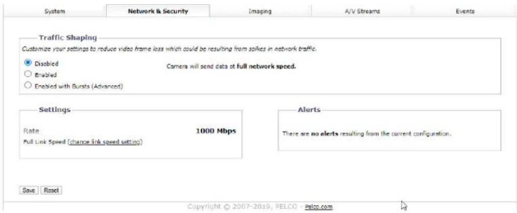
Configuring Traffic Shaping
You can use the traffic shaping function if the frame rate at your client is significantly lower than you would expect from the camera.
Your camera can produce large I-frames, resulting in a traffic burst within each group of pictures as the camera transmits the frame; if your network infrastructure does not have the speed or buffering capacity to smooth out the traffic, you might experience slow or jittery video. From the Traffic Shaping page, you can control the average transmission rate over a 2 ms period and limit traffic bursts coming from the camera to help you prevent frame losses at your client resulting from traffic bursts produced by the camera. Use this function if the frame rate at your client is significantly lower than you would expect from the camera.

Note: Limiting the transmission rate might increase video latency. The setting also limits all of the video data coming from the camera. For this reason, set the limit to more than the video bit rate times the number of connections to the camera that are receiving the data.
-
Go to Network & Security > Traffic Shaping.
-
Enable Traffic Shaping with or without bursts, depending on your need.
-
Disabled: Camera will send data at full network hardware link speed (For example: 100 Mbps or 1 Gbps).
- Enabled: Camera will limit the rate at which it sends data. In this setting, the "averaging period" (the period over which the rate limit is valid) is 1 ms. The rate limit for this setting is 12.5 Mbps < R < 100 Mbps.
-
Enabled with Bursts: This advanced setting allows you to specify the maximum burst size that the camera can send at the hardware link speed. This balances video latency with the transmission rate.
-
Set the average transmission rate over a 2 ms period in Mbps when enabled with bursts.
-
If you enabled traffic shaping with bursts, set the maximum size of bursts coming from the camera in kilobytes.
-
Click Save.
Configuring 802.1x Security
By default, 802.1x security is off. Cameras support EAP-MD5, EAP-TLS, EAP-TTLS, EAP-PEAP, and EAP-FAST protocols.
- Go to Network & Security > 802.1x.
- Select On for 802.1x port security.
- Select the (EAP) method from the Protocol drop-down menu.
- Provide the authentication information for the EAP method you selected.
- Click Save.
Configuring SNMP
Your camera supports No SNMP, SNMP V2c, and V3, and it can be configured to send traps. The MIB file for your camera is available at www.pelco.com.

Note: SNMP V2c and SNMP V3 configuration settings are independent of each other, but only one SNMP mode can be active.
Configuring the SMTP Server
Providing the address of an SMTP server enables your camera to send email notifications when using the Send Email event handler.
- Select SNMP from the Network and Security menu.
- Type the address of your SMTP server in the SMTP Server box.
- Click Save.
Configuring SNMP V2c
- Click SNMP from the Network menu.
- Click SNMP V2c.
- Complete the fields under SNMP V2c.
- Click Save.
Configuring SNMP V3
- Click SNMP from the Network menu.
- Click SNMP V3.
- Complete the fields under SNMP V3.
- Click Save.
Firewall Configuration
Your camera supports Firewall Configuration and it can be configured to block or allow up to 10 IP addresses to access the camera.

Note: Incorrect configuration of these settings can result in being locked out of the camera.
Configuring Firewall Settings
- Go to Network & Security > Firewall.
-
Click Off, Allow, or Deny from the Mode drop-down menu.
-
Off: The default setting is Off. Disables Firewall Configuration.
- Allow: Allows all IP addresses entered to view the camera.
-
Deny: Denies all IP address entered to view the camera.
-
Type up to 10 IP addresses in CIDR format in the boxes provided.

Note: Incorrect configuration of these IP addresses can result in being locked out of the camera. All IP addresses entered will either be allowed or denied. You cannot allow some IP addresses and deny others. To prevent being locked out:
- Allow Mode: Ensure workstation IP address/network does appear.
-
Deny Mode: Ensure workstation IP address/network does not appear.
-
Click Save.
Using the Imaging Menu
The Imaging menu contains 3D noise reduction, digital processing, exposure, flicker correction, day/night, white balance, window blanking, and alignment settings for your camera.
Configuring General Imaging Settings
General Imaging settings adjust the color and detail of captured video. The availability of settings might change based on your camera model.
Quick Setup: Contains presets for digital processing settings. You can use any of the quick setup modes as starting points for custom settings; changing sharpness, saturation, contrast, or brightness settings automatically engages the Custom mode.
- Normal: A baseline setting in which sharpness, saturation, contrast, and brightness are all set to zero.
- Vivid: A setting that enhances color quality, lightens whites, and darkens blacks.
- Custom: Allows you to set your own, unique image quality settings.
3D Noise Reduction: Adjusts for video noise in low-light scenes. Turn off 3D noise reduction if details are blurred in moving objects.
Defog Mode: The Defog Mode feature allows you to make the subject appear clearer when the surrounding area of the subject is foggy and low contrast. Choose High, Medium, Low, or Off for this mode. Low is used for slightly hazy conditions with a minimal amount of correction. High is used for foggier conditions and maximizes the amount of correction.
Sharpness: Controls the clarity of detail in the scene. Increasing video sharpness increases video noise.
Saturation: Controls the intensity of colors in the scene.
Contrast: Controls the gradation between the darkest and lightest portions of the scene.
Brightness: Controls the lighting detail of the scene.
Tone Compensation: Controls the intensity of red or blue hues in a scene.
Restore Settings to Defaults: Restores the Imaging General page settings to the camera's default settings.
Restore All Imaging Settings: Restores all of the camera's Imaging settings to default imaging settings for that camera.
Configuring Exposure Settings
Exposure settings, accessed from the Imaging tab, Exposure option, help ensure that video contains an adequate level of detail and contrast between light and dark values.
- Select Exposure from the Imaging menu.
- Select your camera's Exposure Mode.
- Auto: Allows you to set maximum Gain limit and Exposure Time limit settings, while retaining the full range of Day/Night controls.
- Manual: Allows you to specify the Exposure Time and adjust the Gain. You should only engage this mode if fixed exposure time is a priority.
- Set the Max Exposure Time or the Exposure Time, depending on the exposure mode you selected. The maximum exposure time determines the time, in milliseconds, that the imaging sensor is
exposed to light. Decreasing the maximum exposure time reduces motion blurring; increasing the maximum exposure time could help capture more detailed still images in low light.
- Set the Max Gain or the Gain, depending on the exposure mode you selected. Increasing the gain allows for better sensitivity in low-light scenes, but also increases video noise.
- Set your Day/Night Mode. If you've set your camera's exposure mode to the Exposure Time/Gain Control setting (Manual Mode), the Day/Night Mode setting becomes the Position setting.
- Auto: Engages day or night mode based on the Transition Level setting; this allows you to capture color video (Day) when enough light is available, and automatically switch to black and white video (Night) when light is unavailable.
- Manual/Position: Requires you to choose a Day or Night mode. Day captures color video; Night captures grayscale video.
-
(Optional) If you selected the Day/Night Auto Mode, set the Transition Level, determining whether the transition is Lighter, Default, or Darker. Lighter settings cause the camera to change modes at higher lux values.
-
If necessary, use Restore Settings to Defaults to reset the camera settings to the factory defaults on the current page only, or use Restore All Imaging Settings to reset all of the camera settings to the factory defaults on all Imaging pages.
Setting White Balance
Each Sensor has its own white balance settings. Auto mode is the default setting for each sensor. Selecting Manual mode allows you to adjust white balance settings for the sensor.
Auto: the default white balance mode. It has a color temperature range from 7,500K to 2,500K. It can be used to properly balance scenes illuminated by daylight to warm white sources.
Manual: Allows for several options. Use Manual mode to set Basic, White Patch, and Color chart adjustments.
To set white balance:
-
Select a sensor to configure its white balance. select Manual mode to adjust that sensor's white balance manually.
-
Basic: Adjusts the red and blue range. Move each slider to increase or decrease the color level.
- White Patch: Select White Patch to adjust the white balance in a similar manner as if using a white piece of paper to adjust the white balance. After selecting White Patch, the scene from the camera is presented. If there is an area that should be white, select in that area of the scene, and then drag the mouse to select that portion of the scene to adjust the white balance. If no white area exists, temporarily use a white piece of paper to adjust the camera's white balance.
- Color Chart Allows adjustment of th following color options: Dark Skin, Bluish Green, White, and Black. Using the X-Rite ColorChecker® Classic 24 patch target, place the target in the camera's field of view, following the on-screen instructions.
Using the Window Blanking Feature
Window Blanks, or privacy masks, will block sections of your camera's image from being viewed. Blanked areas persist in all video produced from the camera, whether viewing video directly through the camera's interface or from a higher-level recording device or system.
To create window blanks:
- Go to Imaging > Window Blanking.
- Select On to enable Window Blanking.
- Click and drag the mouse across the video area that you want to blank. Select an existing blanking region to delete it, or edit its size and position.
- Click Save.
The Edit Window displays each blanking window you have set. To edit a blanking window:
- Select a window in the Edit Window or in the Preview Display to move or resize the blanking window.
- Select X to erase and close a blanking window.
Realigning the Camera Sensors
The camera's sensors are factory-aligned with an optimal field of view between 4 to 30-meters (12 to 98-feet) from the camera. You should only realign the camera if it is obvious that the camera's factory alignment is inadequate for your use, i.e. if there is noticeable duplication between sensors. You might need to realign the camera if it becomes misaligned as a result of physical shock, or if you need to capture a scene containing objects closer than 4 meters. Adjusting for objects closer than 4 meters will increase parallax errors for objects farther from the camera.
Find the current camera's sensor alignment configuration under Sensor Alignment. There are three alignment modes:
- Automatic Align mode initiates an automatic operation in which the camera determines the best points to align the sensors. Automatic alignment may take up to 5 minutes to complete. Navigating away from the Alignment page does not interrupt automatic alignment; you can continue to configure the camera.
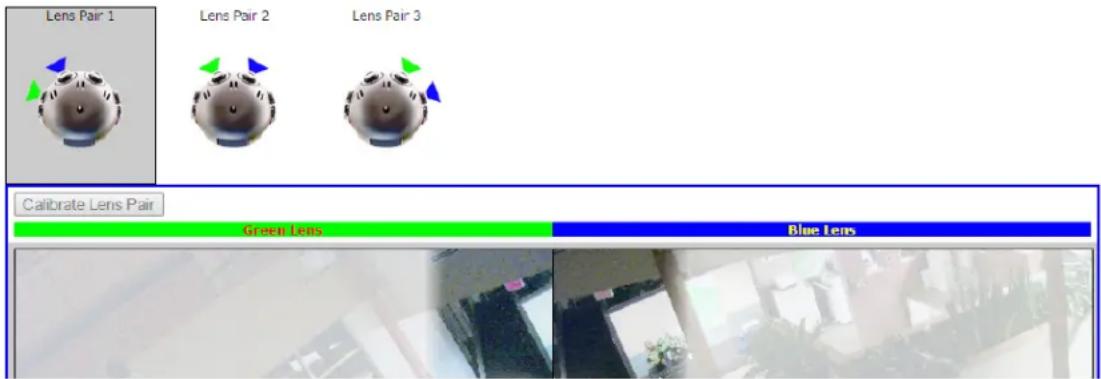
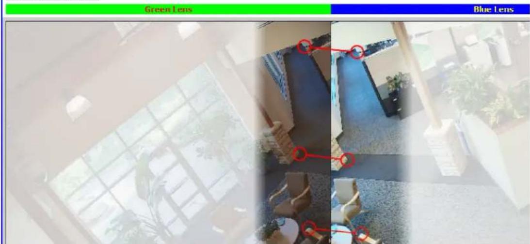
- Manual Align mode allows you to click the specific point pairs used to align the camera's sensors. You must click at least three point pairs per sensor pair to successfully align the camera.
- Restore Factory Alignment mode restores the camera's sensors to the original factory alignment.
Manually Aligning the Camera Sensors

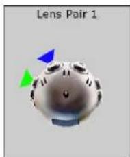
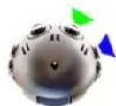
Note: Each lens thumbnail includes an area of focus indicated by an unshaded region. You will click a minimum of three point pairs from this unshaded area for each lens pair. Spread the point pairs apart to ensure the best result.
- Click Alignment from the Imaging menu.
- Clilck Manual Align.
-
Identify identical points in the unshaded area between the green and blue lenses. Click a point in the Green Lens thumbnail; the scene zooms in so that you can click the exact point for the pair.
-
Click the identical point in the Blue Lens thumbnail. The scene again zooms into the point selected.

Note: If you click a point by mistake, click in the shaded area to restart the process.
- From within the magnified scenes click identical points for the point pair. Move your mouse from the focused area to zoom out and continue creating point pairs.
If a point pair is undesirable, you can click the point pair to delete it.
- When you have created at least three point pairs, click Calibrate Lens Pair. You are automatically advanced to the next camera lens.
natural_image
3D rendered object with colored triangular indicators (blue, green, blue arrow) pointing to its surface, labeled 'Lens Pair 1' above.Lens Pair 2

Lens Pair 3
Calibrate Lens Pair
-
Repeat the previous steps until all sensors are aligned.
-
When you have calibrated all sensors, review the camera's sensor alignment from the Live page to verify the alignment results.
Using the A/V Streams Menu
The A/V Streams menu contains settings for your camera's video and audio streams as well as local recording, RTP settings, and Smart Compression.
Configuring a Custom Video Configuration
The Video Configuration page contains settings for customizing your camera's Mosaic and Full video streams.
The Mosaic video stream is a low resolution composite of the video streams. You can create a custom configuration of the Mosaic video streams.
Full video streams must have the same configuration. Depending on the model, the camera produces between two and five full resolution video streams.
The compression standard, resolution, image rate, bit rate, and I-frame interval settings are dependent on each other. You must first decide the setting you want to take priority before you configure a stream. For example, if you want an image rate of 30 ips, set the image rate before you configure the other settings.
Depending on your camera, by default all fields on the Video Configuration page are populated with settings from your Video Presets. You can clear all fields, or use the default settings as a starting point for your custom stream. Configure the Mosaic stream before the Full stream. The Mosaic stream should be the most resource-intensive video stream.
- Go to A/V Streams >Video Configurations.
- Select the maximum frame rate (e.g. 10 fps, 12 fps, or 12.5 fps). These settings affect both the Mosaic and Full resolution configurations.
- (Optional) Provide a user-friendly name, which is typically Primary, Secondary, or Tertiary, for your custom streams in the Stream Name box (2 to 64 alphanumeric characters).
- Mosaic
- Select the Image Rate. For H.264 encoding, select I-frame Interval, profile, QoS (DSCP) Codepoint, Endura Signing, and rate control for the Full stream.
- Click Save.
Configuring Video Settings
Compression Standards: Available compression standards depend upon the model of the camera that you are using.
Resolution: The quality of the video stream, rendered in pixels for both width and height. Higher values result in greater video quality but consume more bandwidth.
Bit Rate: The quality of the video stream, rendered in kilobits per second. Higher values result in greater video quality but consume more bandwidth.

Note: When you change video stream configuration settings, the camera automatically adjusts the bit rate. Choosing a bit rate below the camera's automatic setting might reduce video quality and limit stream configuration options.
I-Frame Interval: Determines the number of partial frames that occur between intra-coded frames (I-frames) in your video stream. I-frames are complete images, used as a reference for change in the following video frames. Following an I-frame, the camera will capture and encode only video data in the scene differing from the I-frame until the next I-frame.

Note: This setting is only available for H.264 video streams. Increasing the I-frame interval can improve video compression rates and reduce the size of video data; however, higher values are recommended only for highly-reliable networks.
Profile: Defines the subset of bit stream features in an H.264 stream, which includes color reproduction and additional video compression. It is important you select a profile that is compatible with your recording device(s) to ensure that your camera's video stream can be decoded and viewed.
- Main: An intermediate profile with a moderate compression ratio. This profile is compatible with most recorders and uses fewer bits to compress video than the baseline profile, but more bits than the high profile. The main profile supports I-frames, P-frames, and B-frames.
- High: A complex profile with a high compression ration. This is the primary profile for high-definition television applications. The high profile supports I-frames, P-frames, and B-frames.
Quality of Service (QoS) for Different Services Code Point (DSCP): A mechanism for prioritizing network traffic. This setting is available only with H.264 compression standards. Your network must be QoS-aware to take advantage of this setting. If you are unsure if your network is QoS-aware, contact your network administrator.
Endura Signing: Allows an Endura® system to authenticate recorded video streams. This setting is available with H.264, H.265, and MPEG-4 compression standards.
Rate Control: Determines the bit rate and quality of each frame in the H.264 or H.265 video stream. Each rate control setting is a compromise between image quality and the resources required for video storage. The availability of rate control settings depend upon the model of the camera that you are using.
- CBR: The constand bit rate (CBR) streams video at fixed number of bits per second. CBR uses the full capacity of the bit rate setting for scenes with or without motion. Video is always streamed at the user bit rate setting.
- CVBR: The constrained variable bit rate (CVBR) provides high-quality video and long recording time of variable bit rate in response to motion, while not exceeding the user-defined maximum bit rate over a period of several GoPs.
Configuring Audio
Not all camera models are equipped with an internal audio device. If your camera does not support audio natively, you must connect an audio device to the accessory port to capture audio. You can only enable audio through the primary video stream.
Audio is disabled by default, but you can enable and configure audio streams from the Audio Configuration page.
Audio and video might not be synchronized when viewing the primary stream through a Web browser. You might experience up to a 3-second delay in video when viewing the primary stream with audio enabled.

Note: Improper use of audio/visual recording equipment may subject you to civil and criminal penalties. Applicable laws regarding the use of such capabilities vary between jurisdictions and may require, among other things, express written consent from the recorded subjects. You are solely responsible for ensuring strict compliance with such laws and for strict adherence to any/all rights of privacy and personality.
- Go to A/V Streams > Audio Configuration.
- Enable Audio.
-
Select your sample rate. The sample rate is the quality of the audio stream (measured in hertz per second).
-
Select your Audio Device.
- Native Line In: Enables audio from a microphone connected to the audio-in connector.

Note: Only available for products with built-in audio support.
- Microphone: Enables audio from the internal microphone.

Note: Only available for products with a built-in microphone.
-
Select the encoding method.
-
Set the Input Level. Input sensitivity is measured on a scale from 0 to 100 (low to high).

Note: If the camera is installed in a noisy environment or the connected microphone has a built-in line amplifier, you should lower audio sensitivity.
- Click Save.
Managing Local Recording
-
Place your mouse pointer over the A/V Streams tab, and select Local Recording from the drop-down menu.
-
Click the REC button to enable or disable local recording. The following colors indicate the status of the local recording feature:
Red: Recording enabled.
Gray: Recording disabled.
Yellow: An error has occurred, typically caused by a missing micro SD card, a micro SD card that was previously used or reformatted and has reached the end of its life, or the camera's time settings being improperly configured.
Configuring Local Recording
The number of hours of video you can store on the micro SD card depends on several factors besides the capacity of the micro SD card. The bit rate is an important factor. For example, with a 32 GB card at 1080p with a maximum controlled variable bit rate (CVBR) of 7 Mbps, you can store over 10 hours of video. Scenes with lower complexity and less motion, which allow for lower resolutions and frame rates with lower bit rates, result in longer recording times. You can, for example, record more than 48 hours of video at standard definition of 1.5 Mbps CVBR.
There is, however, a limit on the total number of frames that can be stored on the micro SD card. For example, below a bit rate of 1.5 Mbps, you can store a maximum of 48 hours of video at 30 fps on a 32 GHz card. You can increase the maximum available hours of storage by decreasing the frame rate.
The number of hours of video you can store on the SD card is established with recording bit limits. A bit rat limit below 1.5 Mbps allows a maximum of 48 hours of video at 30 fps regardless of resolution. You can increase the maximum available hours of storage by decreasing the frame rate.
Managing RTP Settings
The RTP Settings page provides access to advanced multicast and MTU (TCP/IP) settings.
Setting Static Multicast Addresses
A multicast stream sends video data to multiple users from the same transmission. Each multicast user connecting to the camera consumes no additional processing power.
You can set static multicast addresses and ports for all of your camera's multicast streams (primary, secondary, tertiary, service, etc.).
Default, automatically-assigned multicast addresses are confined to the 239.x.x.x block in a scheme matching your IP address and network settings; you can determine the automatically-assigned multicast address(es) for your camera from the RTP page.
- Go to A/V Streams > RTP Settings.
- Enter static multicast addresses and ports for your streams as necessary.
- Set the Time to Live (TTL) for each stream; this is the number of routers the stream can pass through before it expires.
- Determine whether or not to Always Multicast this stream. This setting eliminates the need for a client to connect to the camera to initiate a stream; when enabled, the camera begins sending the multicast stream when it starts up, without requiring initiation from a client.
- Click Save.
Setting the Maximum Transfer Unit Size (TCP/IP)
You can adjust the maximum transfer unit size to adjust to your network's constraints. Changing the MTU setting will require your camera to restart. This could take several minutes.
- Go to A/V Streams > RTP Settings.
- Set the Max Transfer Unit size.
- Click Save or Save and Reboot Camera, depending on your camera.
Smart Compression
Smart Compression can greatly reduce the bit rates produced by your camera at the potential cost of a slight to moderate degradation in video quality, depending on the compression level you set. This change in video quality is dependent on the complexity of the scene and the compression level you select. The High Smart Compression setting can reduce the bit rate up to 90% of the expected bit rate.
From the Smart Compression page, you can also set a dynamic group of pictures (GoP) length, allowing the camera to update picture groups depending on scene composition and motion. A dynamic GoP can further reduce bit rates produced by the camera, by allowing the camera to increase the GoP length when there is little action in the scene.

Note: Dynamic or long GoP lengths may cause compatibility issues with some video management systems (VMS). Ensure your VMS supports dynamic GoP settings before enabling this setting.
Configuring Smart Compression
- Go to the Smart Compression page from the A/V Streams page.
- Indicate your Smart Compression Level.
The Smart Compression level allows you additional control to balance video quality versus bit rate.
The smart compression settings determine how aggressively the camera will drop the bit rate on easily compressed scenes and how aggressively it will adjust image processing settings to make the scene more compressible. If the scene is difficult to compress (high motion, high noise), the camera will use the full bit rate allowed by the stream bit rate settings. The “off” and “low” settings
Optera™ Operations Manual
will have a similar, minor effect on the image; he “medium” and “high” settings will have correspondingly more effect on the image and greater savings on storage.
- (Optional) Enable Dynamic GoP Length.
a. (Optional) Set the maximum GoP length for your streams if you want to limit the upper limit of the dynamic GoP setting.

Note: Dynamic or long GoP lengths may cause compatibility issues with some video management systems (VMS). Ensure your VMS supports dynamic GoP settings before enabling this setting.
- Click Save.
Using the Events Menu
The Events menu contains settings for camera events and analytics pages.
An event is a user-defined occurrence, consisting of a source and a handler. A source defines the trigger for an event; a handler defines the action your camera will take when the event source occurs. When configuring a source, you can link the source to multiple handlers, providing multiple outcomes for the event. When configuring a Handler, you can link the handler to multiple sources, providing a single outcome for multiple events.
Analytics are specialized event sources that are triggered by the user-defined behaviors or scenarios occurring within your camera's field of view. Analytics are compatible with VideoXpert™ or third-party systems that support events using ONVIF or Pelco's API. The analytic behaviors available for your camera are dependent on your model and firmware version.
There is also an analytic you can configure called 2 Camera Tracking. This analytic is tied to Pelco Camera Link, a technology feature that requires two different types of Pelco Cameras (e.g. Optera and a Pelco Enhanced Series PTZ camera) to set up.
Event Stream
The Event Stream displays a list of alerts triggered by an active analytic behavior. The alert includes a screen capture, the profile that was triggered, and the zone in which the event was detected.
Configuring Sources
An event source defines the trigger for an event, something that must occur before your camera takes action (defined by a handler). Event Sources that can be configured include Alarm, Analytics, Timer, System, and Network Loss events.
Configuring an Alarm Event Source
An alarm source triggers an event upon a signal from external signaling devices, such as a door contact or a motion detector.
- Select Sources from the Events menu.
- Go to Events > Sources.
- Click New or select the source you want to edit.
- Provide a name, between 2 and 23 alphanumeric characters, for the event source in the Name box.
- Select Alarm from the source Type .
- Select the alarm you want to trigger when an event occurs from the Alam drop-down menu.
- Set the dwell time for the alarm between 1 and 25 seconds. Dwell time is the amount of time that the source will remain active during an alarm event.
- Select the polarity of your alarm input (normally open or normally closed).
- Select either True or False from the Supervised drop-down menu.
- (Optional) If available, select the handler(s) that you want to associate with this source. Handlers are configured from the Events menu Handlers page.
- Click Submit.Click Save.
Configuring an Analytic Event Source
An analytic event source triggers an event when a behavior defined by a video analytic occurs.
- Select Sources from the Events menu.
- Go to Events > Sources.
- Click New, or select the existing source you want to edit.
- Provide a name, between 2 and 23 alphanumeric characters, for the event source in the Name box.
- Select Analytics from the source Type.
- (Optional) If available, select the handler(s) that you want to associate with this source. Handlers are configured from the Events menu Handlers page.
- Click Submit.Click Save.
Configuring a System Event Source
A system source triggers an event when your camera boots.
- Select Sources from the Events menu.
- Go to Events > Sources.
- Select New Source, or select the source you want to edit.
- Provide a name, between 2 and 23 alphanumeric characters, for the event source in the Name box.
- Select System from the source Type .
- (Optional) Click to select Boot, if you want the event to trigger when the camera starts up or reboots.
- (Optional) If available, select the handler(s) that you want to associate with this source. Handlers are configured from the Events menu Handlers page.
- Click Submit.Click Save.
Configuring a Timer Event Source
A timer event source triggers an event at specified intervals of time.
- Go to Events > Sources.
- Click New, or select the source you want to edit.
- Provide a name, between 2 and 23 alphanumeric characters, for the event source in the Name box.
- Select Timer from the source Type.
- Configure the frequency of the event, including the units of time available, in the pull-down menu.
- (Optional) If available, select the handler(s) that you want to associate with this source. Handlers are configured from the Events tab Handler page. Handlers are configured from the Events menu Handlers page.
- Click Submit.Click Save.
Deleting an Event Source
- Go to Events > Sources.
- Select the source that you want to delete.
- Click Delete to remove the event source.
Configuring Handlers
Event handlers are the actions that your camera takes when an event source occurs. The availability of handlers might change based on your camera model.
Configuring an Event Handler: Send Email
The Send Email event handler sends an email from your camera when a source event is triggered.

Note: You must have provided your camera with the address of an SMTP mail server on the System > General Settings page for your camera to send email notification for events.
- Go to Events > Handlers.
- Click New or select the handler you want to reconfigure.
- Provide a name, between 2 and 23 alphanumeric characters, for the event handler in the Name box.
- Select the Send Email handler Type.
- Provide the necessary information for your email in the To, From, Subject, and Message boxes.
- (Optional) Select the JPEG Snapshot box if you want to send a JPEG snapshot as an attachment to the email.
- (Optional) Select the Attach Raw Event Data box if you want the email to include extra data about the event. For example, select this box if the event is triggered by an alarm and you want to receive data about the state, time, or type of alarm.
- (Optional) Set time filters to determine the days and times during which the handler will be active. If you do not select any filters, the handler will remain active at all times. All time values must be formatted in 24-hour notation.
- (Optional) If available, select the source(s) that you want to trigger this event handler. Sources are configured from the Events menu Sources page. Sources are configured from the Events menu Sources page.
- Click Submit.Click Save.
Configuring an Event Handler: Write JPEG to SD Card
This event handler captures and saves a JPEG to a micro SD card when an event source is triggered.JPEG files are named according to the date and time at which they are recorded; although, you can determine the order of factors in the date-and-time filename.

Note: Do not use the "Write JPEG to SD Card" handler if you enabled local storage through the ONVIF API.Writing JPEGs to the micro SD card disables local storage.
- Install a micro SD card in the slot located on the back of the camera.

Note: The micro SD card must be formatted as FAT32 or reformatted to est4.
-
Select Handlers from the Events menu.
-
Click New Handler or select the handler you want to reconfigure.
-
Provide a name, between 2 and 23 alphanumeric characters, for the event handler in the Name box.
-
Select the Write JPEG to SD Card handler type.
-
Select a time standard from the File Name menu. The JPEG files saved to the micro SD card will be given file names corresponding to the date and time of the event.
-
Provide a size limit for the JPEG images, including the units available, from the pull-down menu. Do not select a size limit that exceeds the available memory on the micro SD card.
- (Optional) Set time filters to determine the days and times during which the handler will be active. If you do not select any filters, the handler will remain active at all times. All time values must be formatted in 24-hour notation.
- (Optional) Select one or more sources that you want to trigger this event handler.Sources are configured from the Events tab Sources page.
- Click Submit.
Configuring an Event Handler: Upload JPEG to FTP Server
This event handler captures and uploads a JPEG to an FTP server when an event source is triggered. JPEG files are named according to the date and time at which they are recorded; although, you can determine the order of factors in the date-and-time filename.
- Select Handlers from the Events menu.
- Go to Events > Handlers.
- Click New or select the handler you want to reconfigure.
- Provide a name, between 2 and 23 alphanumeric characters, for the event source in the Name box.
- Select the Upload JPEG to FTP Server handler Type.
- Provide the address of your FTP server in the Server box.
- Provide the credentials the camera will use to authenticate with the FTP server; the User Name must be between 1 and 32 alphanumeric characters, and the Password must be between 4 and 16 alphanumeric characters.
- Provide the path in which to store JPEG files on your FTP server in the Base Path box.
- Select the File Name for your JPEG snapshots. The selection is simply the format of the date and time stamp.
- (Optional) Set time filters to determine the days and times during which the handler will be active. If you do not select any filters, the handler will remain active at all times. All time values must be formatted in 24-hour notation.
- (Optional) If available, select the source(s) that you want to trigger this event handler. Sources are configured from the Events menu Sources page.
- Click Submit.Click Save.
Configuring an Event Handler: Open/Close Relay
The Open/Close handler opens or closes a relay when a source event occurs.
- Select Handlers from the Events menu.
- Go to Events > Handlers.
- Click New or select the handler you want to reconfigure.
- Provide a name, between 2 and 23 alphanumeric characters, for the event handler in the Name box.
- Select the Open/Close Relay handler type.
- Select the individual relay you want to trigger when an event occurs from the Relay handler Type.
- Use the On Time controls to set the amount of time the relay will remain open, up to 200 seconds.
-
Use the Off Time controls to set the amount of time the relay will remain closed, up to 200 seconds.
-
Set the Pulse Count for the relay. The pulse count is the number of relay pulses (number of on and off cycles).
-
(Optional) Set time filters to determine the days and times during which the handler will be active. If you do not select any filters, the handler will remain active at all times. All time values must be formatted in 24-hour notation.
-
(Optional) If available, select the source(s) that you want to trigger this event handler. Sources are configured from the Events menu Sources page.
-
Click Submit.Click Save.
Deleting an Event Handler
-
Go to Events > Handlers.
-
Select the handler that you want to delete.
-
Click Delete.
Analytic Configuration
The Analytic Configuration page allows you to analyze the camera's field of view to detect and trigger events or alarms when specific activity occurs.
Multiple analytic behaviors can be configured (Go to Events > Analytic Configuration). However the complexity of active behaviors and zones per behavior may increase the processing load on your camera. Once configured, your camera will monitor your defined zones for activity violating the parameters of the behavior. You can view analytic events through your camera's event stream (Go to Events > Event
Streams). However, analytic alarms are only transmitted through Pelco's API, and are therefore only available with compatible VMS systems or through direct integration.
You can configure multiple analytic behaviors. Each analytic behavior has its own settings, and many analytic behaviors also require you to configure zones that the camera will monitor for activity. The analytic behaviors available to your camera are dependent on your model and firmware version.
Configuring Profile Settings
Profile settings define the attributes of a normal scene within the field of view of your camera, providing context for analytic behaviors. Properly configured profile settings help ensure the accuracy of analytic behaviors. Each profile contains the following profile settings:
- Camera Preset: Selects a camera preset for the profile.
- Scene Type: Determines whether or not the scene is indoor or outdoor.
- Background: Determines the expected amount of background movement in the scene; the background can be still or noisy. A stable background with few moving objects should be set to Still. A busy background, with many moving objects should be set to Noisy.
- Fine Tuning: Defines zone violation sensitivity. Available settings include Conservative, Normal, or Aggressive. The Conservative setting is the least sensitive setting, reducing the number of false alarms, but might prevent the camera from detecting zone violations. The Aggressive setting is the most sensitive setting, detecting all suspect violations, but might cause the camera to trigger more false alarms.
- Sensitivity: Defines the relative amount of motion, between 1 (low) and 10 (high), that will trigger a behavior. The higher the setting, the greater the chance for false alarms; lower settings will reduce the chance of false alarms, but might result in missed violations.
Applying Select Behaviors
Behaviors analyze the camera's field of view to detect and trigger events or alarms when specific activity occurs. You can configure multiple analytic behaviors per profile. However, each analytic behavior has its own settings; many analytic behaviors also require you to configure zones that the camera will monitor for activity. The analytic behaviors available to your camera are dependent on the your model and firmware version.
Each analytic behavior contains a number of settings determining the conditions under which events are triggered. The settings available are dependent on the analytic behavior that you are configuring.
- Alarm at (Object Counting): Determines the number of objects entered into a zone that will trigger an alarm.
- Alarm severity: Defines the severity of alarms triggered. Alarm severity helps you and other users prioritize alarms.
• Average Height: Defines the average height of objects to track.
• Average Object Size: Determines the average size of objects to be counted.
• Average Width: Defines the average width of objects to track.
- Camera Placement: Defines the vertical height of the camera's location relative to the area being monitored.
- Delay before alarm: Defines the amount of time an object must remain in a zone before triggering an alarm. For the Camera Sabotage behavior, this defines the delay between a scene violation and the trigger of an alarm.
- Direction: Determines the direction of motion a zone should track. Events will only be triggered when your camera detects motion in the specified direction.
- Dwell time: Defines the amount of time that an alarm will remain active when an alarm-triggering object exits the field of view or the zone.
- Enable Alarm: Enables a zone alarm. Analytic events for the zone will appear in the event stream when viewing live video, and trigger event handlers if the Analytic Event source is enabled.
- Follow Options: Determines whether an object is tracked only within the current field of view or beyond.
- Maximum Object Size: Defines the maximum size of objects tracked. Observe the location of where you place this element and the relationship to the perspective of the scene.
- Minimum Object Size: Defines the minimum size of objects tracked. Observe the location of where you place this element and the relationship to the perspective of the scene.
- Optimize Zoom Settings for Objects of this Type: Defines the type of object to be tracked.
- Sensitivity: Overrides the global Profile sensitivity setting for the selected behavior, defining the relative amount of motion, between 1 (low) and 10 (high) that will trigger an event or alarm. Sensitivity is an advanced option for some behaviors.
- Zone Sensitivity: Defines the relative amount of motion within the selected zone that will trigger an event or alarm. Zone sensitivity can be set at a lower or higher setting than the overall sensitivity setting for the rest of the scene or the Profile sensitivity setting for the selected behavior.
- Object speed: Adjusts for speed if the scene is configured to track moving objects at a slower or faster rate than actual speed.

Note: When advanced options are enabled for AutoTracker or Stopped Vehicle behaviors, any excluded zones that you have previously created within the scene are disabled. You can create additional excluded zones, but the zones will remain exclusive to the behavior within the selected profile.
2 Camera Tracking
The 2 Camera Tracking behavior is tied to Pelco Camera Link, a feature that provides the ability to couple the full hemispherical coverage of the Optera cameras to the 30x zoom capability of Pelco's Enhanced Series PTZ cameras (e.g. Spectra Enhanced, Esprit Enhanced and ExSite Enhanced). Pelco Camera Link provides an automatic PTZ operator that uses the analytic information from Optera to point and zoom the Enhanced Series PTZ camera onto the scene. Pelco Camera Link can be installed on any existing Optera camera and any existing Enhanced Series PTZ camera (firmware version 2.11 or later). Purchasing a new camera is not required.
Ideal Scene Setup for Abandoned Object Analytics
Pelco Camera Link provides the Auto Tracking function even if the Optera and the Enhanced Series PTZ camera are mounted in the same location or if they are mounted completely separate from the other camera. The cameras do not need to be in sight of one another, but must have some overlapping of the view space. A low traffic area is ideal for setting up Pelco Camera Link (e.g. Pelco Camera Link is not designed for heavy traffic areas such as airports.).
Pelco Camera Link operates with all Optera models, including Optera 180, 270, and 360.
A single Optera camera can provide analytic information to one, two, or multiple Enhanced Series PTZ cameras. This allows auto tracking from different views, or for one Enhanced Series PTZ camera to follow one moving object, while a second Enhanced Series PTZ camera follows a different object.
Setup of Pelco Camera Link can be done completely from a PC through the camera's web UI. No measurements or blue prints are required to determine the position of the Enhanced Series PTZ camera relative to the Optera camera to enable accurate Auto Tracking. A one-time setup is all that is required to calibrate the position of an Enhanced Series PTZ camera in relation to an Optera camera.
For details on how to set up Pelco Camera Link, please see the Setting Up and Operating Pelco Camera Link section of the manual.
Abandoned Object
The Abandoned Object behavior detects objects placed within a defined zone and triggers an alarm if objects remain in the zone longer than the user-defined time allows.
Ideal Scene Setup for Abandoned Object Analytics
Install the camera in a ceiling or against a wall with the lens pointing at a slight downward angle, above regular motion activities.
The ideal scene for the Abandoned Object behavior contains light traffic where people or objects within the field of view are continually moving, there are minimal obstructions, and the background is clean. If heavy traffic or a busy background is unavoidable, place monitoring zones in relatively stable areas.
Avoid crowded scenes where people or objects remain in one place for long periods of time.
Adaptive Motion
The Adaptive Motion behavior detects and tracks objects that enter a scene and then triggers an alarm when the objects enter a user-defined zone.
The Adaptive Motion behavior is designed to work indoors and outdoors to track a few moving objects in uncrowded fields of view. The behavior learns the background scene over time and adjusts to changing conditions like snow, fog, wind, and rain.
Ideal Scene Setup for Adaptive Motion
Install the camera in a ceiling or against a wall with the lens pointing at a slight downward angle, above regular motion activity.
The ideal scene for Adaptive Motion behavior is one with light traffic and a clean background. If heavy traffic or a busy background is unavoidable, place zones in a relatively stable area.
Avoid crowded scenes where people move in all directions or stand in place for long periods of time.

Note: Objects that are very small might not be classified as the correct object type. This could result in false alarms or alarms not being triggered. If objects appear too small in the scene, zoom in on the particular zone of interest or move the camera closer to the zone of interest to increase the relative size of the objects in the scene.
Camera Sabotage
The Camera Sabotage behavior detects contrast changes in the field of view, and triggers an alarm if the lens is obstructed by spray paint, a cloth, or if it is covered with a lens cap. Any unauthorized repositioning of the camera also triggers an alarm.
Ideal Scene Setup for Camera Sabotage
Install the camera in a high position, looking down on the scene. The field of view should be as large as possible. A small field of view could result in the view being blocked by an adjacent object.
Avoid scenes with a dark, uniform background, low lighting, and large moving objects.
Using Directional Motion
The Directional Motion behavior generates an alarm in a high traffic area when a person or object moves in a specified direction. Examples of typical installations for this behavior include airports, entrances and exits, and vehicle traffic through tunnels.
- In an airport installation, cameras observe passengers boarding a plane in a terminal. If a person moves in the opposite direction of the normal flow of traffic, an alarm triggers.
- In a tunnel installation, an operator wants to observe traffic flow. If a car enters a tunnel through an exit, an alarm alerts the operator to activate the traffic signals to stop all traffic in the tunnel.
- In an entrance or exit installation, a camera is pointed at an exit door. If a person tries to enter through the exit door, an alarm triggers.
Ideal Scene Setup for Directional Motion
Install the camera in a ceiling or against a wall with the lens pointing at a slight downward angle, above regular motion activity. The width of the object you want to detect should be at least one-tenth of the total width of the scene. To achieve increased accuracy in a crowded scene, set the width of the object to one-sixth of the total width of the scene.
The ideal scene selection for the Directional Motion behavior contains light traffic with all people and objects moving in the same direction, minimal obstructions, and a clean background; however, the behavior can be used in settings that do not meet all of these requirements. If heavy traffic or a busy background is unavoidable, place zones in a relatively stable area.
Avoid crowded scenes in which people move in all directions or stand in one place for long periods of time.
Loitering Detection
The Loitering Detection behavior identifies when people or vehicles remain in a defined zone longer than the user-defined time allows. This behavior is effective in real-time notification of suspicious behavior around
ATMs, stairwells, and school grounds.
Ideal Scene Setup for Loitering Detection
Install the camera in a ceiling or against a wall with the lens pointing at a slight downward angle, above regular motion activity.
The ideal scene for Loitering Detection behavior is one with light traffic and a clean background. If heavy traffic or a busy background is unavoidable, place the user-defined zone in a relatively stable area.
Avoid crowded scenes where people move in all directions or stand in one place for long periods of time.
Object Counting
The Object Counting behavior counts the number of objects that enter a user-defined zone. This behavior can be used to count people at a store entrance/exit or inside a store where the traffic is light. It might also be used to monitor vehicle traffic on highways, local streets and roads, parking lots, and garages.
Ideal Scene for Object Counting
If you plan to detect people, install the camera pointing downward (vertically) above regular motion activity. If you plan to detect vehicles, install the camera pointing downward at a slight angle above regular motion activity.
The ideal scene for the Object Counting behavior contains light traffic, minimal obstructions, and a clean background. If heavy traffic or a busy background is unavoidable, place zones (polygon or line) in relatively stable areas.
A one-directional motion scene (for example, a vertical hallway) is preferable. Avoid crowded scenes in which people or objects move in all directions or remain in place for long periods of time.
Object Removal
The Object Removal analytic behavior triggers an alarm if an object is removed from a user-defined zone. It is ideal for detecting the removal of high-value objects, such as a painting from a wall or a statue from a pedestal.
Ideal Scene for Object Removal
Install the camera in a high position looking down on the scene. The monitored object should occupy a quarter of the camera scene, and the field of view should be as wide as possible.
The ideal scene selection for the Object Removal behavior is a clean background with stable lighting and minimal obstruction.
Stopped Vehicle
The Stopped Vehicle behavior detects vehicles stopped near a sensitive area, and sets an alarm if the vehicle is present for longer than a user-specified period of time. This behavior is ideal for parking enforcement, identifying suspicious parking, finding traffic lane breakdowns, and spotting vehicles waiting at gates.
Ideal Scene for Stopped Vehicle
Install the camera in a ceiling or against a wall with the lens pointing at a slight downward angle, above regular motion activities.
The ideal scene for the Stopped Vehicle analytic behavior contains light traffic in which vehicles are continually moving, there are minimal scene obstructions, and the background is clean. If heavy traffic or a busy background is unavoidable, place monitoring zones relatively stable areas.
Avoid crowded scenes where people or objects remain in place for long periods of time.
Zones
Some analytic behaviors require you to configure zones. A zone is a defined boundary that your camera monitors for an analytic behavior. A zone can be defined by a polygon or line. Zones defined by polygons trigger analytics based on motion within the zone; zones defined by lines trigger analytic events when an object within the scene crosses the line.
When configuring a zone-based analytic behavior, you can draw zones by selecting one of the zone-drawing tools, and then selecting within the scene to draw the zone.

Note: This zone configuration is different from the configuration performed in the Imaging tab PTZ Zone page.

Note:
- The availability of zone drawing tools is dependent on the analytic behavior you are configuring.
- Zones will not scale proportionally with changes in zoom. Set the zoom level for the camera before defining zones.
 | Box: Tracks objects in a defined zone and triggers an alarm if the objects move in the same direction as defined. |
 | Polygon: Tracks objects in a defined zone and triggers an alarm if the objects move in the same direction as defined. |
 | Line: Tracks objects that cross a line and triggers an alarm if the objects move in the same direction as defined. |
 | Exclude Zone Box Tool: Ignores objects inside a defined zone. |
 | Exclude Zone Polygon Tool: Ignores objects inside a defined zone. |
 | Object Size Filter: Sets the minimum and maximum object size for a zone. |
 | Display Size: Sets the size of a tracked object, relative to the surrounding scene, and maintains the size of the object within the scene. |
Configuring an Analytic Profile
A profile consists of profile settings, the behaviors you want to operate on the profile, and the zones you want to monitor for selected behaviors. The instructions below describe how to configure a profile, but there are many settings and possibilities for each step below; the following sections provide a detailed understanding of the settings and controls available for each behavior.
- Select Analytic Configuration from the Events menu.
- Click New to create a new profile or select the profile you would like to edit.
- Configure Profile Settings.
- Calibrate the scene. select Calibrate Scene, adjust the scene accordingly, and then select Return to Main View.
- Select a behavior.
Optera™ Operations Manual
-
Configure advanced settings for the behavior.
-
Configure zones for the behavior.
-
Select Activate Behavior to ensure that the behavior and all zones are enabled when you run the profile.
-
Repeat the previous 4 steps to activate additional behaviors on the profile.
-
Click Save.
Calibrating a Scene
The Calibrate Scene option, under Profile Settings, allows you to adjust an analytic profile's scene setup to reflect the perspective and viewing angle of your camera. A properly calibrated scene makes the object sizes you set when configuring zones for a behavior more meaningful, increasing the accuracy of analytics.
It is important that you calibrate the scene before running a profile. If you find that you are encountering an excess of false alarms, or are not registering normal analytic alarms, you might need to recalibrate the scene for the profile.
-
Select Analytic Configuration from the Events menu.
-
Select the profile for which you want to calibrate the scene, or create a new profile.
-
Click Calibrate Scene.
-
(Optional) Click Pause to pause the field of view if the scene contains moving objects. This allows you to more easily calibrate the scene and focus on near and far objects.
-
Adjust each of the blue boxes to account for objects in the scene. There is at least one box, and there might be boxes for objects at the near left, near right, and an object in the distance; drag the boxes over appropriate objects, and adjust the size of each box to approximate the size of the object the box overlays.
-
Set the real-world height of an object used in the calibration.
-
Click Set Width and set the width of both a near object in the scene and a far object in the scene.
-
Click Return to Main View.
-
Finish adjusting the profile, and then click Save.
Running Profiles
An analytic profile must be running for your camera to monitor the profile for analytic behaviors.
The complexity of each profile, including active behaviors and zones per behavior, increases the processing load on your camera. If the camera cannot support the processing requirement of a profile, either due to the complexity of the profile itself, or because other profiles are also running, you will not be able to run the profile.
-
Select Analytic Configuration from the Events menu.
-
Select the profile you want to run or stop.
-
Click Run to activate the profile or Stop to deactivate the profile.

Note: Stopping or deleting a profile deactivates all of the behaviors associated with that profile, including motion detection enabled through the Pelco API.
Setting Up and Operating Pelco Camera Link
Three steps are required to install, enable, and verify that Pelco Camera Link Auto Tracking is working. First, establish a connection between the Optera and the Pelco Enhanced Series PTZ camera. Second, set
up 2 Camera Tracking for the Optera. Third, calibrate the position of the Enhanced Series PTZ camera relative to the Optera.
After setup, Pelco Camera Link provides controls to verify that the cameras are aligned correctly and that auto tracking is operating correctly. Before setting up Pelco Camera Link, install and turn on both the Optera and Pelco Enhanced Series PTZ cameras using standard procedures. Verify that the cameras are operating and that both can be access from a web interface. Note the IP addresses from the cameras that are to be connected with Pelco Camera Link. Both Optera and the Pelco Enhanced Series PTZ camera must have firmware version 2.11 or later.
Setting Up Pelco Camera Link
Step #1 (Enhanced Series PTZ Connection): First, establish a connection between the Optera and Enhanced Series PTZ camera.
- Open a web page and enter the IP address for the Enhanced Series PTZ camera.
- Login and select Settings, PTZ, and Pelco Camera Link. Three red stop lights show the status. All three lights turn green when the cameras are linked and ready to operate together.
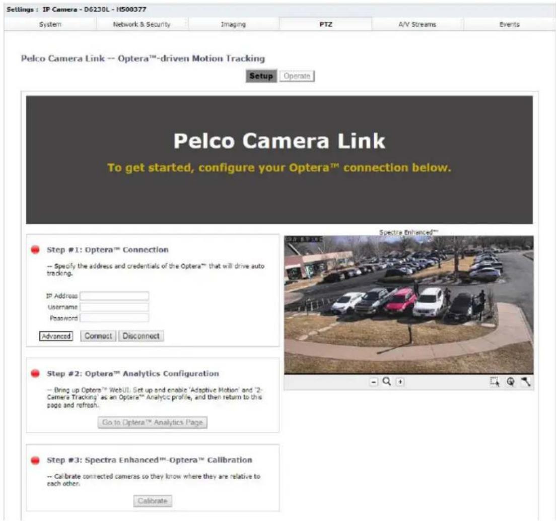
Step #1 Continued (Optera Connection): Next, connect the Optera camera.
- Enter the IP address of the Optera that will provide analytic information to the Enhanced Series PTZ camera, enter username and password, and click Connect. If the connection is successful, the light turns green and the panoramic view from Optera appears at the top of the screen. You are now viewing both Optera and the Enhanced Series PTZ reduced resolution video on this web page.
| Settings: TP Cameras - D6230L - H500377 | |||||
| System | Network & Security | Imaging | PTZ | A/V Streams | Events |
Pelco Camera Link -- Optera™-driven Motion Tracking
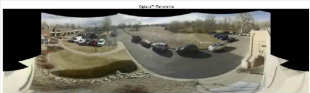
natural_image
Panoramic view of a residential area with parked cars and a paved road, no visible text or symbols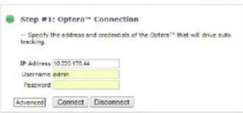
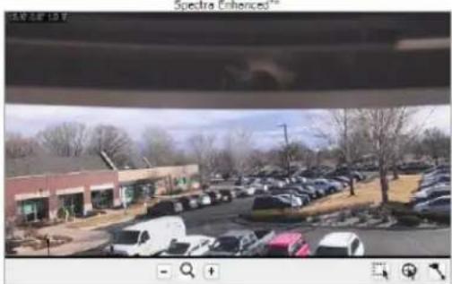
natural_image
Exterior view of a commercial building with parked cars and trees in the foreground (no visible signage or text)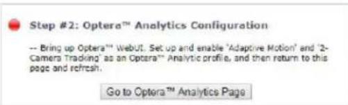
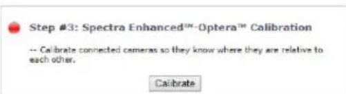
Pelco Camera Link with Auto Tracking uses the Optera 2 Camera Tracking analytic. To set up Pelco Camera Link 2 Camera Tracking, follow the steps below.
Step #2 (Optera Analytics Configuration): From the Enhanced Series PTZ webpage, select Go to Optera Analytics to open a new tab showing the analytics setup page from the Optera. Note the IP address for the Optera is shown as the URL. One tab is the Enhanced Series PTZ and one tab is Optera.
- Select a New Profile, name it if desired.
- Select 2 Camera Tracking.
- Configure Profile Settings, Indoor/Outdoor, etc.
Optera™ Operations Manual
- For Pelco Camera Link, Sensitivity = 6 and Consistency = 2 are the recommended settings to start with, but may need to be adjusted depending on the scene.
- Calibrate the scene. A Calibrate page appears.
- On the Calibrate page, place the blue box at a distant point in the view and adjust the height of the box to match the height of a typical object at that distance. If needed, enter the height in the entry box.
- Select Set Width and position and adjust the length of the yellow bars of a typical object at a close distance, and at a far distance.
- When complete, select Return to Main Menu. This returns to the Analytics Page.
- Set Exclude Zone for the 2 Camera Tracking Analytic. The analytic detects motion over the entire Optera scene. However, if desired, a portion of the scene can be excluded from the analytic. For example, a portion of the scene below is viewing inside the building through the windows. If only the motion over the patio is desired, excluding the building windows is possible using the Exclude zone tools.
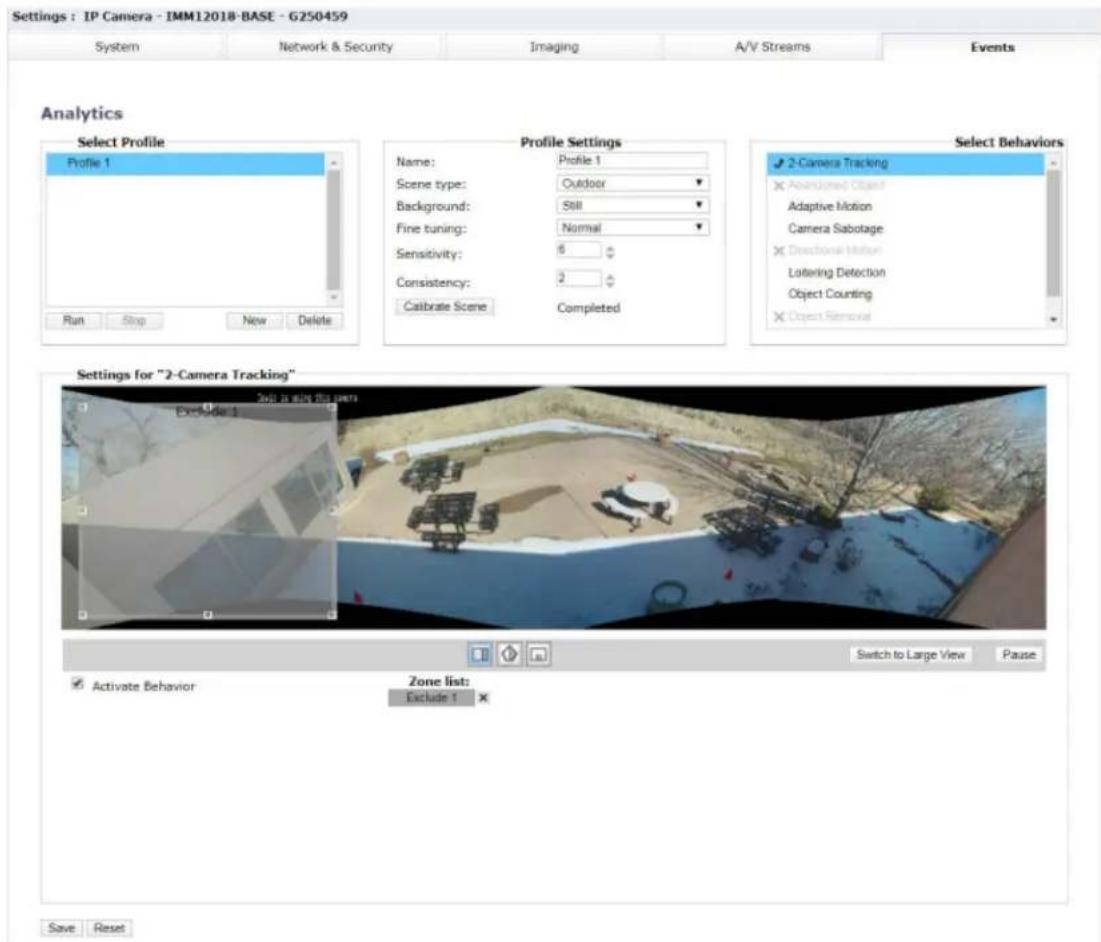
- Activate the behavior.
- Click Save. This saves the setup for analytics into the Optera camera memory. As with settings for Pelco cameras, a backup copy of settings can be saved by selecting Backup from the system Tab.
-
Click Run.
-
Return to the Enhanced Series PTZ tab. The stoplight next to Analytics Configuration should be green. (Refreshing this page may be required for some browsers.)
Step #3 (Calibration): The final step for Pelco Camera Link setup is to calibrate the position of the Enhanced Series PTZ relative to Optera. Calibration is only required one time when first turning on Pelco Camera Link. A critical element for Pelco Camera Link tracking is that all tracked motion occurs in one plane. During calibration, the user must select matching points in the motion plane.
- Click Calibrate. This brings up a step-by-step process.
- Select mount-type and mutual visibility of the cameras. Mutual visibility means that the Spectra is visible in the Optera view, and that by adjusting the Enhanced Series PTZ camera's pan and tilt, the Optera is visible in the Enhanced Series PTZ's view. If the cameras are mounted together, neither camera is visible to the other. But if the cameras are mounted separately in many cases each camera is viewable by the other camera. After answering the two questions, select Next.
- Calibration guides the user through a series of steps where four points from each camera are matched. These points must be in the plane of motion that Optera will track. In most cases, this will be points on the ground or floor of the scene. These four points allow the Enhanced Series PTZ and Optera to determine the location and orientation of each camera to enable Pelco Camera Link Auto Tracking. Calibration is most accurate if the user can select matching points in several regions as shown in the unshaded portions of the camera view below. Some installations will not allow this. In that case, attempt to choose points in the motion plane that are separated as much as possible. Also, some installations may show a small red region where you should not select matching points. This area is excluded to prevent incorrect geometry solutions. For each point, use the mouse to position the matching points in the center of the box, then Save the point and click Next. Careful matching of the points will result in the best calibration results.

Note: The plane of motion can be a tilted plane relative to the Earth (e.g. the plane could be on a hillside).
-
After selecting the four points, Submit these and the camera will calculate the geometry. A calibration score is displayed, along with recommendations on whether the points provide a good geometrical solution. Careful choice of points provides the highest score. Also, note that it is possible to ReDo the Calibration changing only one or two points. The calibration points are saved for reference and adjustment when redoing calibration. Redoing all four points is not required.
-
Click on Setup to go back to modify any setup steps performed, or to verify and use Pelco Camera Link.
Operation Manual: After calibration, all three stoplights on the Setup page should be green. Clicking Operate puts the Enhanced Series PTZ camera into a mode where you can verify calibration and analytics.
There are several controls in the Operate page. Tracking Mode allows Manual Tracking, Off, or Automated. Setting to Manual lets the user select either Move PTZ Camera to Mouse select or Zoom PTZ Camera to Mouse-Drawn Box. To verify good Calibration, click Move and select different points in the Optera view. The Enhanced Series PTZ view will move to that point and display the video. Selecting the Mouse-Drawn Box will position the Enhanced Series PTZ at that point and zoom into or out of the view.
Operation Auto: Choosing Auto Tracking Mode puts turns on the automatic 2 Camera Tracking where analytics from the Optera will drive the Enhanced Series PTZ camera. As the Optera detects motion, a box will show in the Optera video and the Enhanced Series PTZ will position to show a high magnification view of that motion. If the Optera detects multiple moving objects, multiple boxes will be displayed. The box that the Enhanced Series PTZ camera is following will show with a red frame. If the user selects on a box, that box becomes the priority, turns red, and is the motion object that is tracked.
Three controls allow configuring the Motion Tracking:
Optera™ Operations Manual
- Priority: Largest, Fastest, and Farthest Object let the user select the analytic detected object the Pelco PTZ will follow.
- Sticky Follow On and Off: Set to On, the PTZ camera will continue to follow the original object that was detected even if other objects are detected, even if other objects are larger, faster, etc. The Sticky Follow will stay with the original object until it is stationary for some period of time.
- Movement Sensitivity: This control allows the user to select sensitivity of the motion. A high setting will track small motions, a lower setting will disregard small movements such as sawing trees and blowing leaves, and only track large movements such as cars driving and people walking. However, setting too low may disregard people walking and only track faster moving cars.
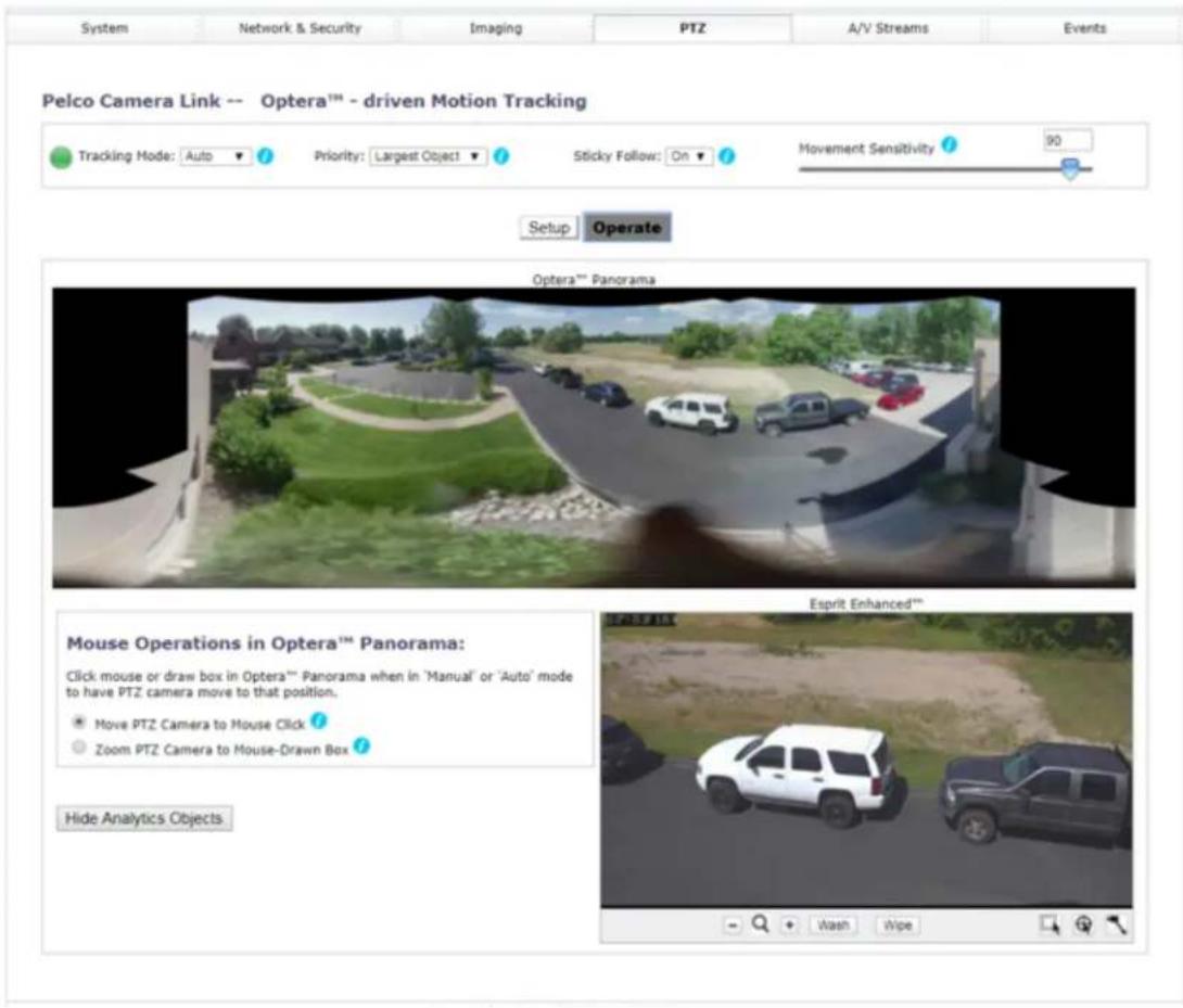

a Motorola Solutions Company

Pelco, Inc.
625 W. Alluvial Ave., Fresno, California 93711 United States
(800) 289-9100 Tel
(800) 289-9150 Fax
+1 (559) 292-1981 International Tel
+1 (559) 348-1120 International Fax
www.pelco.com
Pelco, the Pelco logo, and other trademarks associated with Pelco products referred to in this publication are trademarks of Pelco, Inc. or its affiliates. ONVIF and the ONVIF logo are trademarks of ONVIF Inc. All other product names and services are the property of their respective companies. Product specifications and availability are subject to change without notice.
© Copyright 2018, Pelco, Inc. All rights reserved.
- Table of Contents
- Optera™ Operations Manual
- Important Notices
- Regulatory Notices
- Radio and Television Interference
- Warranty Statement
- Legal Notice
- Audio Notice
- Video Quality Caution
- Frame Rate Notice Regarding User Selected Options
- Open Source Software
- Power Source
- Accessing the Camera
- Accessing Camera Settings
- Accessing the Live Video Page
- Live Video Controls
- Using the System Menu
- Changing the Camera Name
- Enabling and Disabling LEDs
- Optera Compatibility Mode
- Tiled Mode (Assembling Panoramic Scenes)
- Hardware Requirements for Tiled Mode
- Adjusting the Image Angle
- Corridor Mode
- Install Angle
- Configuring Time Settings
- Generating a System Log
- Restarting the Camera
- Restoring All Camera Defaults
- Backing Up and Restoring Settings
- Back Up Camera Settings
- Restore Camera Settings from a Backup
- Firmware
- Configuring OSDi Overlays
- Snapshot Viewer
- Onboard Storage Management
- Using the Network & Security Menu
- Changing General Network Settings
- Understanding General Network Settings
- Network Hostname
- Port Settings
- Link Settings
- IPv4 Settings
- IPv6 Settings
- Note:
- Managing Network and Security
- User Management
- Configuring Users
- Setting Security/Authentication
- Configuring TLS
- Enabling SSH
- Configuring Traffic Shaping
- Configuring 802.1x Security
- Configuring SNMP
- Configuring the SMTP Server
- Configuring SNMP V2c
- Configuring SNMP V3
- Firewall Configuration
- Configuring Firewall Settings
- Using the Imaging Menu
- Configuring General Imaging Settings
- Configuring Exposure Settings
- Setting White Balance
- Using the Window Blanking Feature
- Realigning the Camera Sensors
- Manually Aligning the Camera Sensors
- Using the A/V Streams Menu
- Configuring a Custom Video Configuration
- Configuring Video Settings
- Configuring Audio
- Managing Local Recording
- Configuring Local Recording
- Managing RTP Settings
- Setting Static Multicast Addresses
- Setting the Maximum Transfer Unit Size (TCP/IP)
- Smart Compression
- Configuring Smart Compression
- Using the Events Menu
- Event Stream
- Configuring Sources
- Configuring an Alarm Event Source
- Configuring an Analytic Event Source
- Configuring a System Event Source
- Configuring a Timer Event Source
- Deleting an Event Source
- Configuring Handlers
- Configuring an Event Handler: Send Email
- Configuring an Event Handler: Write JPEG to SD Card
- Configuring an Event Handler: Upload JPEG to FTP Server
- Configuring an Event Handler: Open/Close Relay
- Deleting an Event Handler
- Analytic Configuration
- Configuring Profile Settings
- Applying Select Behaviors
- Camera Tracking
- Ideal Scene Setup for Abandoned Object Analytics
- Abandoned Object
- Adaptive Motion
- Ideal Scene Setup for Adaptive Motion
- Camera Sabotage
- Ideal Scene Setup for Camera Sabotage
- Using Directional Motion
- Ideal Scene Setup for Directional Motion
- Loitering Detection
- Ideal Scene Setup for Loitering Detection
- Object Counting
- Ideal Scene for Object Counting
- Object Removal
- Ideal Scene for Object Removal
- Stopped Vehicle
- Ideal Scene for Stopped Vehicle
- Zones
- Configuring an Analytic Profile
- Calibrating a Scene
- Running Profiles
- Setting Up and Operating Pelco Camera Link
- Setting Up Pelco Camera Link
Brand : Pelco
Model : Optera IMM12036-B1I
Category : Security Camera