GV-MFDC1501-0FV - Security Camera Geovision - Free user manual and instructions
Find the device manual for free GV-MFDC1501-0FV Geovision in PDF.


| Product Type | Mini fixed dome security camera with pan/tilt, super low lux CMOS sensor |
| Dimensions | ∅ 106 x 53.9 mm (4.2 x 2.1") |
| Weight | 280 g (0.62 lb) |
| Power Supply | DC 5V / PoE (IEEE 802.3af) |
| Key Features | Super low lux 0.01 Lux color, 2-axis pan (-45°~45°) and tilt (0°~90°), 3D DNR, WDR, Defog, dual H.264 streams up to 30fps at 1280x720, cloud storage, YouTube live streaming, two-way audio, micro SD slot (SD/SDHC Class 10), tampering alarm |
| Maintenance and Cleaning | Clean the camera housing with a soft dry cloth. Avoid using abrasive cleaners or solvents. Check the lens periodically for dust and clean gently. |
| Safety Precautions | Use only the supplied power adapter or PoE. Do not expose to rain or moisture. Install in a well-ventilated area. Do not disassemble the camera. |
| Spare Parts and Repairability | Includes mounting screws, cable stopper, audio cable, Ethernet cable, and 8 GB micro SD card. Additional parts may be obtained from GeoVision. The device is not user-serviceable; contact GeoVision support for repairs. |
| General Information | Brand: Geovision, Model: GV-MFDC1501-0FV, Operating temperature: 0°C~50°C, Humidity: 10%~90% non-condensing, Regulatory: CE, FCC, RCM, RoHS |
Frequently Asked Questions - GV-MFDC1501-0FV Geovision
User questions about GV-MFDC1501-0FV Geovision
0 question about this device. Answer the ones you know or ask your own.
Ask a new question about this device
Download the instructions for your Security Camera in PDF format for free! Find your manual GV-MFDC1501-0FV - Geovision and take your electronic device back in hand. On this page are published all the documents necessary for the use of your device. GV-MFDC1501-0FV by Geovision.
USER MANUAL GV-MFDC1501-0FV Geovision
natural_image
Abstract collage of floating digital photos against a blue sky with clouds, no text or symbols present.
GeoVision Inc
© 2015 GeoVision, Inc. All rights reserved.
Under the copyright laws, this manual may not be copied, in whole or in part, without the written consent of GeoVision.
Every effort has been made to ensure that the information in this manual is accurate. GeoVision, Inc. makes no expressed or implied warranty of any kind and assumes no responsibility for errors or omissions. No liability is assumed for incidental or consequential damages arising from the use of the information or products contained herein. Features and specifications are subject to change without notice.
Note: No memory card slot or local storage function for Argentina.
GeoVision, Inc.
9F, No. 246, Sec. 1, Neihu Rd.,
Neihu District, Taipei, Taiwan
Trademarks used in this manual: GeoVision, the GeoVision logo and GV series products are trademarks of GeoVision, Inc. Windows and Windows XP are registered trademarks of Microsoft Corporation.
March 2015
Contents
Important Notes ......v
Chapter 1 Introduction....1
1.1 Key Features.... 2
1.1.1 myGVcloud Portal, CamViewer and CamApp.... 2
1.1.2 GV-Cloud Cameras 3
1.2 Packing List....6
1.2.1 GV-HCW120 6
1.2.2 GV-UBXC1301 6
1.2.3 GV-UBLC1301 7
1.2.4 GV-MFDC1501....8
1.3 Camera Overview....9
1.3.1 GV-HCW120 9
1.3.2 GV-UBXC1301....11
1.3.3 GV-UBLC1301 12
1.3.4 GV-MFDC1501....13
1.4 Installing the Camera....14
1.4.1 GV-HCW120 and GV-UBXC1301.....14
1.4.2 GV-UBLC1301 15
1.4.4 GV-MFDC1501....18
1.5 Connecting the Camera....20
1.5.1 GV-HCW120 20
1.5.2 GV-UBXC1301 and GV-MFDC1501 21
1.5.3 GV-UBLC1301 22
Chapter 2 Getting Started....24
2.1 Setting Up the Camera....25
2.2 Registering myGVcloud Account....28
2.3 Installing myGVcloud CamViewer or Mobile Applications 30
Chapter 3 myGVcloud Portal....31
3.1 The Main Screen....33
3.2 The Live View Window 34
3.3 Camera Settings....36
3.4 Cloud Service....43
3.5 Remote Playback 45
3.6 Timeline (Cloud)....47
3.7 General Account Settings....48
Chapter 4 myGVcloud CamViewer....49
4.1 Accessing Live View and Recorded Videos....50
4.2 General Setting 52
Chapter 5 myGVcloud CamApp .... 54
5.1 Logging In myGVcloud Account ....55
5.2 Configuring the Camera Settings....56
5.3 Accessing Camera Live View 57
5.4 Playing Back Recordings....59
5.5 Notification 60
5.6 Configure myGVcloud CamApp Settings....61
Chapter 6 Camera Web Interface 62
6.1 Logging in the Camera's Web Interface....62
6.2 List of Menu Option 64
6.3 Event List 65
6.4 Live View....66
6.4.1 The Live View Window 66
6.4.3 Snapshot of Live Video....69
6.4.4 Video Recording....69
6.4.5 Picture-in-Picture and Picture-and-Picture View 70
6.5 Video Settings....72
6.5.1 Streaming 1 / 2....72
6.5.2 OSD 74
6.6 Events and Alerts 75
6.6.1 Notification 75
6.6.2 myGVcloud....76
6.7 Monitoring ....77
6.7.1 Monitoring ....77
6.7.2 Storage Settings....78
6.8 Network....80
6.8.1 Wireless 80
6.8.2 Status....81
6.8.3 LAN 82
6.8.4 Advanced TCP/IP 84
6.9 Management 87
6.9.1 Date and Time....87
6.9.2 User Account....89
6.9.3 Tools 90
6.9.4 Language 91
6.10 Upgrading System Firmware 92
Specifications....93
GV-HCW120....93
Camera 93
Optics Lens....93
Operation 94
Network....94
Mechanical....94
General 95
Applications....95
GV-UBXC1301....96
Camera 96
Optics Lens....96
Operation 97
Network....97
Mechanical....97
General 98
Power over Ethernet....98
Applications....98
GV-UBLC1301....99
Camera 99
Optics Lens....99
Operation 100
Network....100
Mechanical....100
General 101
Power over Ethernet....101
Applications....101
GV-MFDC1501 102
Camera 102
Optics Lens....102
Operation 102
Network....103
Mechanical....103
General 104
Power over Ethernet....104
Applications....104
Appendix 105
A. Settings for Internet Explorer 8 or Later....105
B. Changing the Default Media Player for Event Playback ....106
C. Setting Live Streaming on YouTube or UStream....108
Important Notes
Note for Cloud License
A GeoVision cloud license is required for each GV-Cloud Cameras in order to store recordings to GeoVision's cloud storage. When the cloud license expires:
- The camera stops recording.
- Recordings in the cloud storage are deleted after the number of days specified in the purchase plan (keep days).
- Access to live view is limited to 60 seconds if the camera is in different LAN.
To acquire cloud license, click Purchase in the top-right corner of myGVcloud Portal: www.mygvcloud.com/login.php
Note for Memory Card
- A memory card must be detected in the GV-Cloud Camera in order to store recordings to cloud storage.
- The supplied micro SD card is provided as a complimentary item without warranty.
- Mind the following when using a memory card for recording:
a. Recorded data on the memory card can be damaged or lost if the data are accessed while the camera is under physical shock, power interruption, memory card detachment, or when the memory card reaches the end of its lifespan. No guarantee is provided for such causes.
b. The stored data can be lost if the memory card is not accessed for a long period of time. Back up your data periodically if you seldom access the memory card.
c. Memory cards are expendable and their durability varies according to the conditions of the installed site and how they are used. Back up your data regularly and replace the memory card annually.
d. Replace the memory card when its read/write speed is lower than 6 MB/s or when the memory card is frequently undetected by the camera.
- It is recommended to use memory cards of the following specifications:
a. Micro SD cards of MLC NAND flash, Class 10 for better performance.
b. SD/SDHC cards only. SDXC and UHS-I cards are not supported.
Chapter 1 Introduction
Ideal Solution for Small Businesses
GV-Cloud Camera is a series of light-weight, easy-to-install network cameras designed for small businesses. When motion is detected, the camera saves the surveillance videos in the micro SD card, which can be stored in GeoVision's cloud storage.
The following models are available:
• GV-HCW120: palm-size cube camera with WiFi connectivity
• GV-UBXC1301: Indoor box camera with built-in IR LEDs for night vision
• GV-UBLC1301: Outdoor bullet camera with built-in IR LEDs for night vision
• GV-MFDC1501: Mini fixed dome with pan / tilt function and super low lux image sensor
Remote Access from PC and Mobile Devices
There are three ways to remotely access GV-Cloud Cameras from your PC and mobile devices. You can watch live view and play back recordings of multiple GV-Cloud Cameras.
• myGVcloud Portal: Log in www.mygvcloud.com using Web browsers on PC
- myGVcloud CamViewer: Install myGVcloud CamViewer on PC
- myGVcloud CamApp: Install myGVcloud CamApp on Android or iOS mobile devices
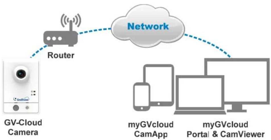
flowchart
graph LR
    A["GV-Cloud Camera"] -->|Router| B["Network"]
    B --> C["myGVcloud CamApp"]
    B --> D["myGVcloud Portal & CamViewer"]
Figure 1-1
1.1 Key Features
1.1.1 myGVcloud Portal, CamViewer and CamApp
| myGVcloud Portal | myGVcloud CamViewer | myGVcloud CamApp | |
| Platform | PC: Log in from Web browsers | PC: Install application in Windows PC | Mobile Devices: Install app in Android / iOS devices |
| Live View | ✓ ✓ ✓ | ||
| Instant Snapshot | ✓ ✓ ✓ | ||
| Remote Playback | ✓ ✓ ✓ | ||
| Motion Event Retrieval | Event list Timeline | Event list Event list | |
| Motion Event Notifications | - Popup notification Popup notification | ||
| Camera Management | Full control - Limited control | ||
| Cloud Service Management | ✓ | - | |
1.1.2 GV-Cloud Cameras
GV-HCW120
• 1/2.5" progressive scan CMOS
- Up to 30 fps at 1280 x 720
- Cloud storage
- YouTube live streaming
- Passive infrared (PIR) sensor for detecting movement and activating the alarm LED in low light
- Wireless connectivity: WiFi 802.11b/g/n
- Two-way audio
- Defog
- Tampering alarm
- Wide Dynamic Range (WDR)
• Dual streams in H.264
• Recording upon motion detection
• Built-in micro SD card slot (SD/SDHC) for local storage
GV-UBXC1301
• 1/2.5" progressive scan CMOS
- Up to 30 fps at 1280 x 720
- Cloud storage
- YouTube live streaming
• Built-in IR LEDs for night vision (Up to 10 m)
- DC 5V / PoE support
- Two-way audio
- Defog
- Tampering alarm
- Wide Dynamic Range (WDR)
• Dual streams in H.264
• Recording upon motion detection
• Built-in micro SD card slot (SD/SDHC) for local storage
GV-UBLC1301
• 1/2.5" progressive scan CMOS
- Up to 30 fps at 1280 x 720
- Cloud storage
- YouTube live streaming
• Built-in IR LEDs for night vision (Up to 10 m)
- DC 5V / PoE support
- Ingress protection for outdoor surveillance (IP67)
• Vandal resistance (IK10 for metal casing)
- Defog
- Tampering alarm
- Wide Dynamic Range (WDR)
• Dual streams in H.264
• Recording upon motion detection
• Built-in micro SD card slot (SD/SDHC) for local storage
GV-MFDC1501
- 1/3" progressive scan super low lux CMOS
- Up to 30 fps at 1280 x 720
- Cloud storage
- YouTube live streaming
• 2-axis mechanism: Pan -45° \~ 45°, Tilt 0° \~ 90° - DC 5V / PoE support
- Two-way audio
- Defog
• 3D DNR (Digital Noise Reduction) - Tampering alarm
• Min. illumination at 0.01 Lux
- Wide Dynamic Range (WDR)
• Dual streams in H.264
• Recording upon motion detection
• Built-in micro SD card slot (SD/SDHC) for local storage
1.2 Packing List
1.2.1 GV-HCW120
- GV-HCW120
- Supporting rack
- Screw x 3
- Screw anchor x 3
- DC 5V power adapter
- Ethernet cable
- 8 GB micro SD card (MLC, SDHC, Class 10)
• myGVcloud Quick Start Guide
Note: The micro SD card is provided as a complimentary item without warranty.
1.2.2 GV-UBXC1301
GV-UBXC1301
- Supporting rack
- Screw x 3
- Screw anchor x 3
- DC 5V Power adapter
- Ethernet cable
• 8 GB micro SD card (MLC, SDHC, Class 10)
• myGVcloud Quick Start Guide
Note: The micro SD card is provided as a complimentary item without warranty.
1.2.3 GV-UBLC1301
GV-UBLC1301
- Cable connector (for waterproof LAN connector)
- Supporting rack
- Black Rubber
- Self Tapping Screw x 3
- Plastic Screw Anchor x 3
- Torx Wrench
- Sun-Shield Cover Kit (Sun-Shield Cover, Philips Head Screw x 2, Plastic Screw Spacer x 2 and Hexagon Screw x 2)
- Silica Gel Bag x 2
• 2-Pin Terminal Block
- Data cable
- DC 5V Power adapter
- Ethernet cable
- 8 GB micro SD card (MLC, SDHC, Class 10)
• myGVcloud Quick Start Guide
Note: The micro SD card is provided as a complimentary item without warranty.
1.2.4 GV-MFDC1501
GV-MFDC1501
- Torx Wrench
- Self Tapping Screw x 2
- Screw Anchor x 2
- Cable stopper
- Short-Body RJ-45 Plug
- Audio cable
- DC 5V Power adapter
- Ethernet cable
- myGVcloud Quick Start Guide
• 8 GB micro SD card (MLC, SDHC, Class 10)
Note: The micro SD card is provided as a complimentary item without warranty.
1.3 Camera Overview
1.3.1 GV-HCW120
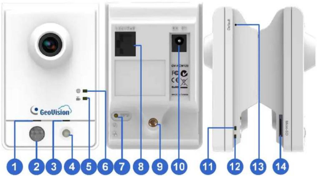
Figure 1-2
| No. | Name Function | ||
| 1 | Speaker Plays sounds. | ||
| 2 | PIR sensor Passive infrared sensor for detecting movement. | ||
| 3 | Microphone Receives the sound. | ||
| 4 | White Illumination LED | When the PIR sensor detects the movement, the white illumination LED lights up in a low light scene. | |
| 5 | Recording LED Shows the recording status of the camera. See the table below. | ||
| 6 | Live View LED Shows the live view status of the camera. See the table below. | ||
| 7 | WPS | Press the WPS button on the camera and on the router to quickly establish connection between the two. | |
| 8 | LAN Connects to a 10/100M Ethernet. | ||
| 9 | Stand screw Connects to the Supporting Rack. | ||
| 10 | Power port Connects to the supplied power adapter. | ||
| 11 | Ready LED Shows the system status of the camera. See the table below. | ||
| 12 | LAN LED | Shows the LAN status of the camera. See the table below. | |
| 13 | Default | Resets the camera settings to factory defaults. | |
| 14 | Memory Card Slot | Insert a micro SD card (SD/SDHC, version 2.0 only, Class 10) to store recording data. | |
| LED Status Description | |||
| Live View |  | Constant orange when connected to the InternetFlashes orange when the live view is being watched. | |
| Recording |  | Constant red when the recording function is enabledFlashes red when recording upon motion detection | |
| Ready |  | Constant green when the system is ready.Flashes green when you load default value. | |
| LAN |  | Constant green when connected to LAN network.Flashes green when camera is transmitting data through InternetConstant blue when connected to WiFi Network.Flashes blue when WPS button is pushed | |
1.3.2 GV-UBXC1301
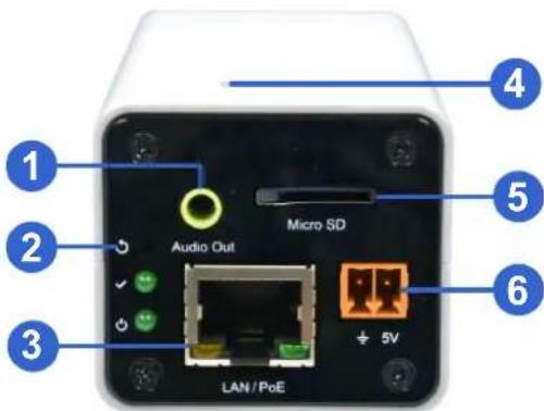
Figure 1-3
| No. | Name Description | |
| 1 | Audio Out Connects a speaker for audio output. | |
| 2 | Default Resets the camera settings to factory defaults. | |
| 3 | LAN / PoE Connects to a 10/100 Ethernet or PoE. | |
| 4 | Microphone Records sounds. | |
| 5 | Memory Card Slot | Insert a micro SD card (SD/SDHC, version 2.0 only, Class 10) to store recording data. |
| 6 | DC 5V Terminal Block Connects to power. |
| LED Indicator Description | |
| Status LED The status LED turns on (green) when the system is ready for use. | |
| Power LED | The power LED turns on (green) when power is supplied to the camera. |
1.3.3 GV-UBLC1301
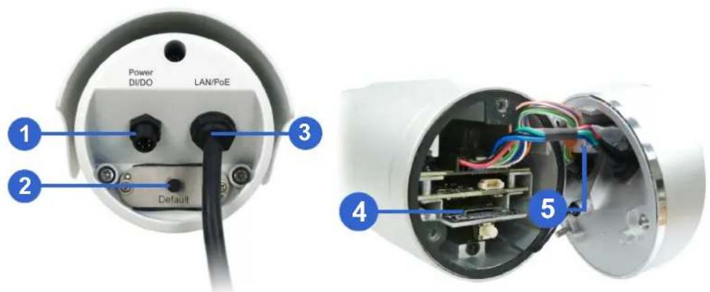
Figure 1-4
| No. | Name Description | |
| 1 | Power Connector Connects to the data cable. | |
| 2 | Default Button Resets the camera settings to factory defaults. | |
| 3 | LAN / PoE Cable Connects to a 10/100 Ethernet or PoE. | |
| 4 | Memory Card Slot | Insert a micro SD card (SD/SDHC, version 2.0 only, Class 10) to store recording data. |
| 5 | Silica gel bag Desiccant that keeps the camera housing dry. | |
1.3.4 GV-MFDC1501
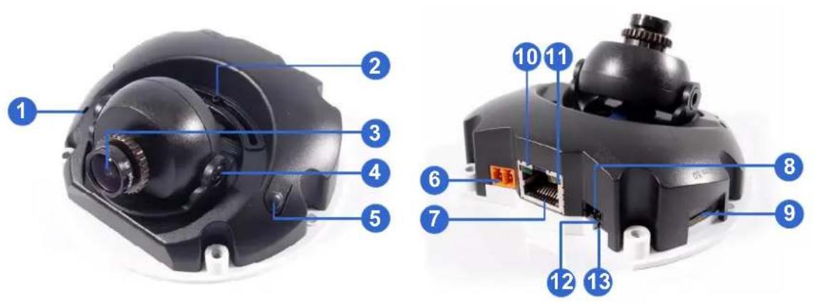
Figure 1-5
| No. | Name Description | |
| 1 | Microphone Records sounds. | |
| 2 | Pan Screw Loosens the screw to adjust pan angle. | |
| 3 | Lens Receives image. | |
| 4 | Tilt Screw Loosens the screw to adjust tilt angle. | |
| 5 | Default Button Resets the camera settings to factory defaults. | |
| 6 | DC 5V Power Port Connects to power. | |
| 7 | LAN / PoE Connects to a 10/100 Ethernet or PoE. | |
| 8 | Memory Card Slot | Insert a micro SD card (SD/SDHC, version 2.0 only, Class 10) to store recording data. |
| 9 | Audio Out | Connects to an external speaker through the supplied audio cable. |
| No. | LED Indicator Description | |
| 10 | Link Turns on (green) when the network is connected. | |
| 11 | ACT | Turns on (orange) when data are being transmitted. |
| 12 | Status | Turns on (red) when the system is ready. |
| 13 | Power | Turns on (green) when power is on. |
1.4 Installing the Camera
1.4.1 GV-HCW120 and GV-UBXC1301
You can place the camera on a flat surface or install it to a wall and ceiling. To simply place the camera on a flat surface, skip to step 5.
- To install the camera onto the wall / ceiling, place the supporting rack where you want to mount the camera and mark the location of the three holes on the base.
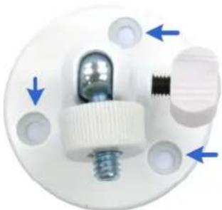
natural_image
Close-up of a white plastic electrical plug with blue directional arrows indicating movement or force (no text or symbols)Figure 1-6
- At the three dots, drill a hole slightly smaller than the screw anchors provided.
- Insert the supplied screw anchors in the drilled holes.
- Secure the supporting rack onto the wall using the supplied screws.
- Insert the supporting rack into the camera and turn to tighten the screw.
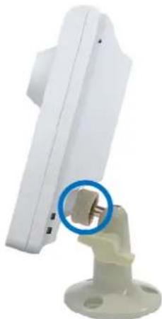
natural_image
Close-up of a white electronic device mounted on a green base with a blue circular annotation highlighting a small component (no text or symbols visible)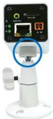
natural_image
Close-up of a white electronic device with a network interface and a blue circular highlight on the base (no readable text or symbols)Figure 1-7
- Insert the supplied micro SD card.
- Remove the protection sticker from the camera's cover.
1.4.2 GV-UBLC1301
- Install the sun-shield cover to the camera.
A. Fasten the hexagon screws to the top or bottom of the camera.
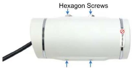
Figure 1-8
IMPORTANT: Do not open the front cover of the camera since this may impair its resistance to water. The warranty is void if the seal is broken.
B. Put the sun-shield cover on top of the hexagon screws. For optimal sun-shield performance, make sure the rear hexagon screw is at the end of the opening.
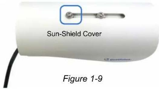
IMPORTANT: The GeoVision logo on the cover should be closer to the front of the camera.
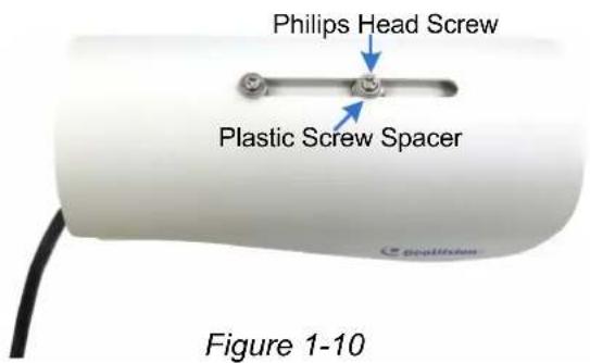
C. Fasten the Philips head screws with the plastic screw spacers.
- Insert a micro SD card to the camera.
A. Unscrew and open the back panel with the supplied torx wrench.
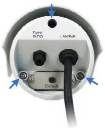
Figure 1-11
B. Insert the supplied micro SD card into the card slot.
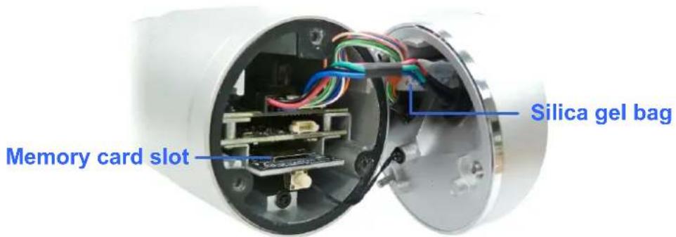
Figure 1-12
C. Replace the silica gel bag.
IMPORTANT:
-
The silica gel loses its effectiveness when the dry camera is opened. To keep the interior dry, replace the silica gel bag every time you open the camera and conceal the gel bag in the camera within two minutes of exposing to the open air.
-
For each newly replaced silica gel bag, allow it to absorb moisture for at least 5 hours before operating the camera.
D. Secure the back cover with the supplied torx wrench.
- Secure the black rubber and the camera stand to the bottom for wall mount or to the top of the camera for ceiling mount.
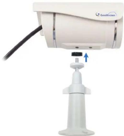
natural_image
Close-up of a Geolision security camera with a blue arrow indicating the cable attachment (no text or symbols on the device body)Figure 1-13
- Install the camera to the wall or ceiling using the screw anchors and self-tapping screws. You can also stand the camera on a plain surface.
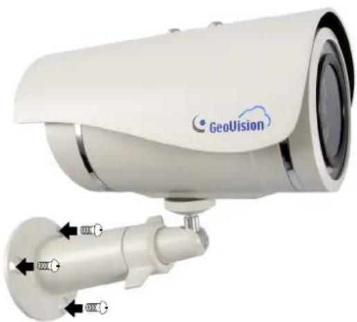
natural_image
Exterior view of a GeoVision security camera with mounted sensor and wall-mounted connector (no text or symbols visible)Figure 1-14
- Remove the protection sticker from the camera's cover.
- Connect the wires and cable connector to the camera. See 1.5.3 UBLC1301.
- Access the live view. For details, see 2.1 Getting Started.
- Adjust angles of the camera body based on the live view.
1.4.4 GV-MFDC1501
- Unscrew the housing cover using the supplied torx wrench.
- Put the camera on the desired location and make 2 marks on the ceiling for screw anchors.
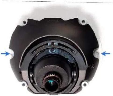
natural_image
Close-up of a mechanical component with central lens and mounting flanges (no visible text or symbols)Figure 1-15
- Drill the marks and insert the screw anchors.
- Secure the camera to the ceiling with the self-tapping screws.
- Connect the camera to network and power. For details, see 1.5 Connecting the Camera.
- Access the live view. For details, see 2.1 Getting Started.
- Adjust the angles based on the live view.
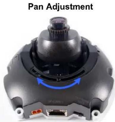
Figure 1-16
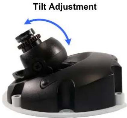
Figure 1-17
- Insert the supplied micro SD card into the memory card slot (Figure 1-12).
-
Secure the housing cover using the supplied torx wrench.
-
Optionally conceal the cable opening with the supplied cable stopper.
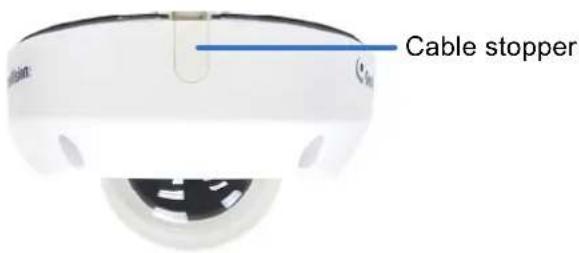
Figure 1-18
1.5 Connecting the Camera
After installing the camera, connect the camera to power, and then connect the camera to your router using the supplied Ethernet cable. For GV-HCW120, you can establish wireless connection with the router.
1.5.1 GV-HCW120
- Use the supplied 5V DC power adaptor to connect the camera to power. The Ready LED will turn green when the camera has finished powering on.
-
Connect the camera to the router.
-
Wired Connection: Use an Ethernet cable to connect the camera to the router.
- Wireless Connection (For GV-HCW120 only): If the router supports WPS function, press the WPS button on the router and the GV-HCW120 in any order for a few seconds. The LAN LED light on the camera will flash blue. When the router and the camera have successfully established connection with each other, the LAN LED will turn into a solid blue.

Figure 1-19
Note:
- On some routers, you may need to log in to the Web interface and enable the WPS feature.
- If the router supports wireless connection but does not have WPS function, use an Ethernet cable to connect the camera to the router. When you run the myGVcloud Cam Wizard, set the camera using wireless connection first, and then you can unplug the Ethernet cable after setup is completed.
1.5.2 GV-UBXC1301 and GV-MFDC1501
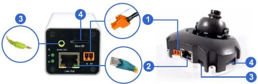
Figure 1-20
-
Connect power using one of the following methods:
-
Plug the supplied power adapter to the 5V terminal block.
- Use the Power over Ethernet (PoE) function and the power will be provided over the network cable.
The power and status LEDs on GV-UBXC1301 shall turn on (green).
- Use the supplied network cable to connect the camera to your network.
- Optionally connect a speaker.
- Insert the supplied micro SD card.
1.5.3 GV-UBLC1301
Waterproofing and Connecting the Network Cable
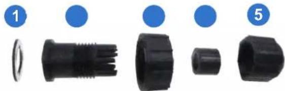
Before connecting the camera, waterproof the LAN / PoE cable on the camera using the supplied cable connector. The cable connector can be dissembled into 5 parts:
natural_image
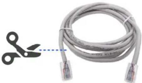
Five black plastic connectors with blue circular indicators (1, 5) pointing to different body parts, no text or symbols present.- Cut off the RJ-45 connector on one end of the Ethernet cable.
natural_image
Coiled gray cable with two connectors and a pair of scissors cutting out the wire (no text or symbols visible)Figure 1-21
-
Connect the Ethernet cable to the LAN / PoE connector (Item A, Figure 1-22) on the camera.
-
Slide the components through the Ethernet as shown below.

Figure 1-22
-
Paste the item 1 sticker to item 2.
-
Move all the components toward the LAN / PoE connector, fit item 4 to item 2, secure item 3 to the LAN / PoE connector (Item A) and finally secure item 5 to item 2 tightly.
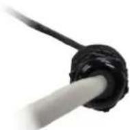
Figure 1-23
IMPORTANT: Item 5 must be secured tightly to waterproof the LAN / PoE connector.
- Prepare an RJ-45 connector, reconnect the RJ-45 connector to the cable, and then connect the camera to network.
Connecting to Power
Connect to power using one of the following methods:
- Use the Power over Ethernet (PoE) function and the power will be provided over the network cable.
-
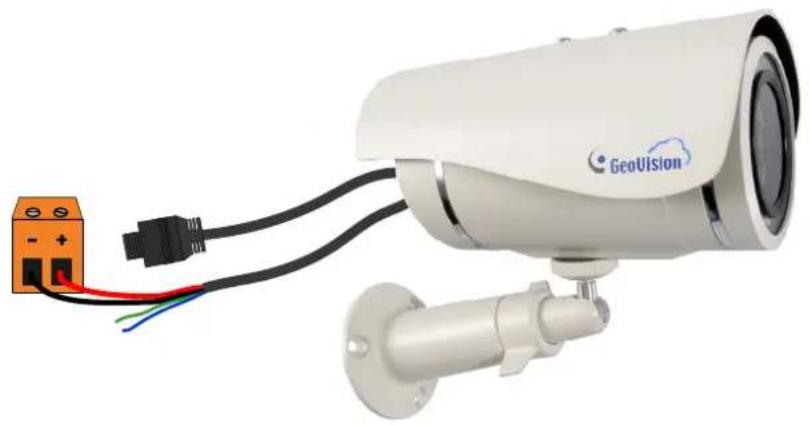
Connect the supplied power adaptor to the terminal block as shown below.
-
Insert the black wire of the data cable to the left pin (-) and the red wire to the right pin (+) of the terminal block.
natural_image
Geovision security camera with mounted sensor and power outlet (no visible text or symbols)Figure 1-24
- Connect the DC 5V power adapter to the terminal block.

Figure 1-25
Chapter 2 Getting Started
There are several ways to access your GV-Cloud Camera.
- Access myGVcloud Portal using a Web browser from http://www.mygvcloud.com
• Install myGVcloud CamViewer on your computer
• Install myGVcloud CamApp on Android or iOS mobile devices
To get started, download myGVcloud CamWizard from:
http://pd.geovision.tw/neo/myGVcloud/Program/myGVcloud_CamWizard.zip
Next, unzip the file, open the folders, and run Setup.exe. This page appears.
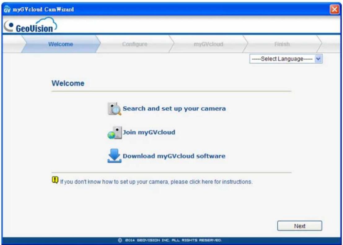
Figure 2-1
The myGVcloud CamWizard will help you configure network settings of the camera, create an account for the camera, and register a myGVcloud account. After setup is complete, you can choose to install myGVcloud CamViewer and / or myGVcloud CamApp.
2.1 Setting Up the Camera
- In the Welcome Screen, click the Next button and the wizard will search for available GV-Cloud Cameras under the same LAN. The search results page appears.
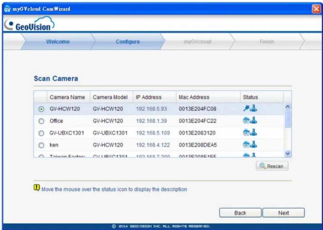
Figure 2-2
The Status column will include some of the icons below.
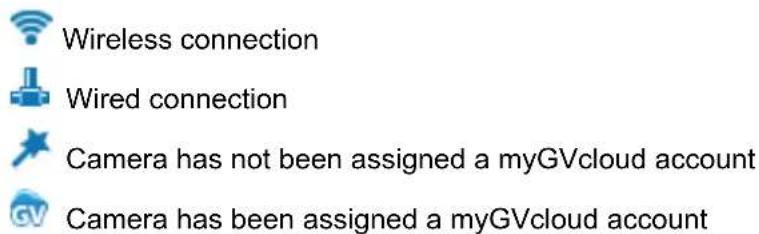
- Select the camera you want to set up and click the Next button.
For GV-UBXC1301, GV-UBLC1301 and GV-MFDC1501, skip to step 4.
For GV-HCW120, a dialog box appears to ask if you want to skip network setup.
- If you have already established connection between the router and the camera using WPS function or if you are using wired connection, click Yes to skip to step 6.
-
If you are using wireless connection without WPS function, click No to proceed to step 3.
-
For GV-HCW120, you can choose Wire Network or Wireless (Wifi). Click Next when you are done.
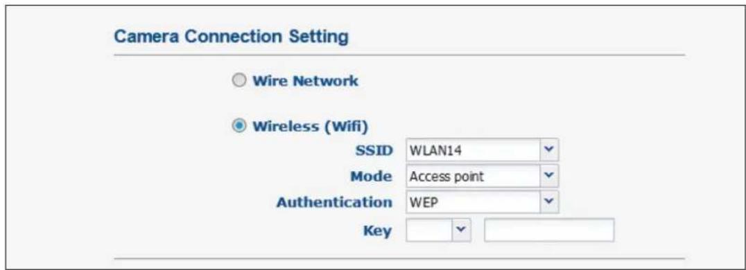
Figure 2-3
- Wire Network: Select if you want to set up wired connection.
- Wireless (Wifi): Select if you want to set up wireless connection.
a. SSID: Type the Network Name (SSID) or select Search Wifi AP to search for the available Access Points/wireless stations.
b. Mode: Select Access Point or Ad-Hoc.
c. Authentication: Select the authentication type.
d. Key: Type the authentication password if needed.
Note: During network setup, the HCW camera needs to be connected to the router through an Ethernet cable. For wireless connection, unplug the cable after setup is completed.
- Select DHCP for dynamic IP address or select Static IP and type the required information.
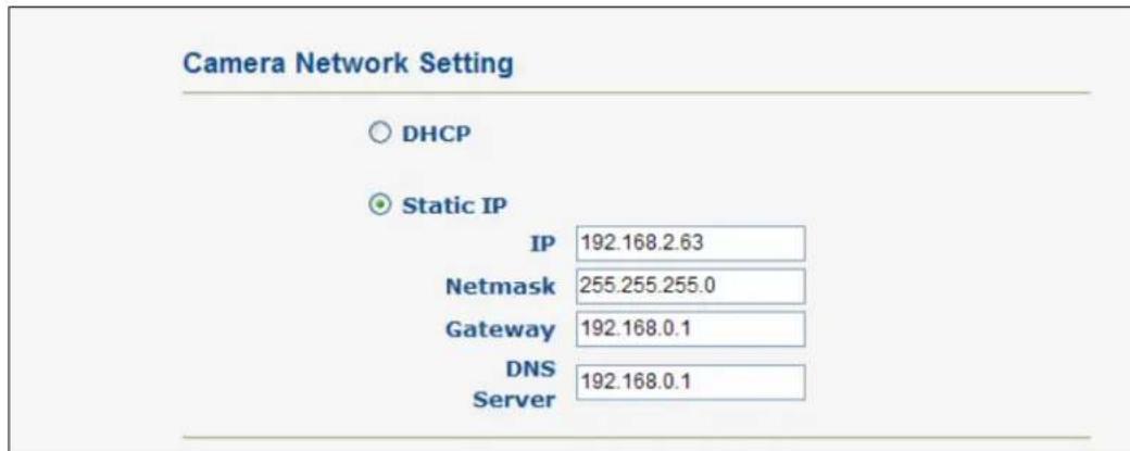
Figure 2-4
- Click Next. The camera will start to establish connection with the router.
- Type a username and password for the camera and click Next.
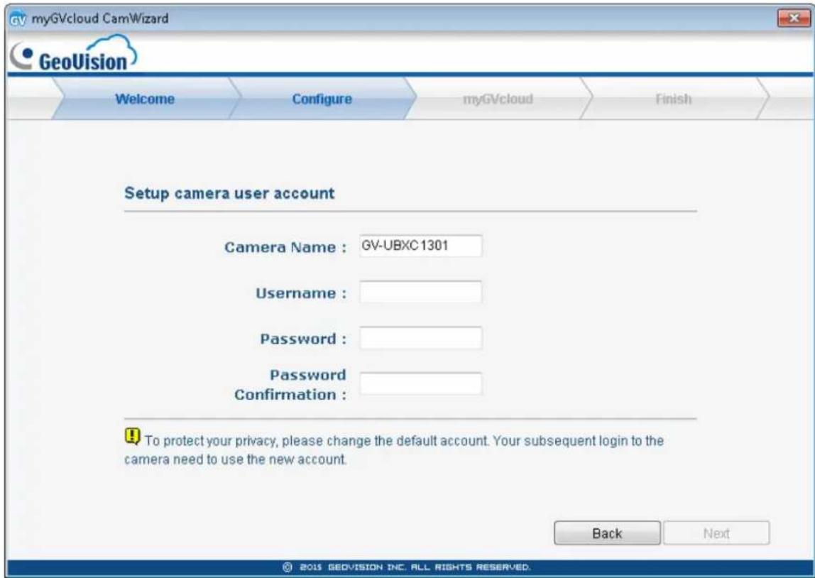
Figure 2-5
IMPORTANT: You will need this information to access the Web interface of the camera. If you forget the username and password, you will need to reset your camera to factory defaults.
2.2 Registering myGVcloud Account
- Select Create a new myGVcloud account and click Next. If you already have a myGVcloud account, select I already have a myGVcloud account, type the account and password, and then click Next.
Link camera to myGVcloud
○ Create a new myGVcloud account.
I already have a myGVcloud account.
Figure 2-6
- To create a new account, type your e-mail for the Account, a Password and a Password Hint.
Create a myGVcloud account
Account : mygvcloud@gmail.com
Password : •••••••
Password
Confirmation :
●●●●●●
Password Hint : workID
Password length of 6-12, the need for the case of letters or figures
Back
Next
Figure 2-7
- Click Next to complete the setup process. An e-mail with a confirmation link will be sent to your e-mail account.
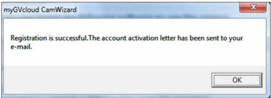
Figure 2-8
- Close the Wizard. An e-mail with a confirmation link will be sent to your e-mail account. You must click the link to activate your myGVcloud account.
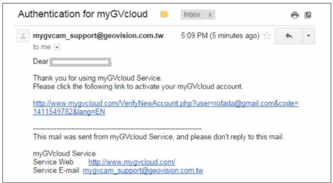
Figure 2-9
The link will also direct you to the login page of myGVcloud Portal: https://www.mygvcloud.com/Login.php
Note: You can assign an unlimited number of GV-Cloud Cameras to a single myGVcloud account. When you sign into myGVcloud Portal, all cameras registered under that account will be displayed.
2.3 Installing myGVcloud CamViewer or Mobile
Applications
After the setup is complete, the screen below appears. You can choose to install myGVcloud CamViewer on PC or myGVcloud CamApp for iOS and Android devices.
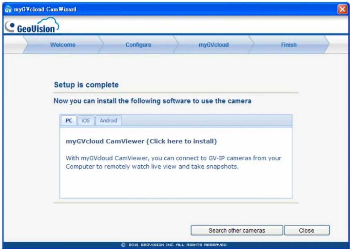
Figure 2-8
You can also install myGVcloud CamApp by searching myGVcloud in Apple Store or Google Play.
For more details, refer to Chapter 4 myGVcloud CamViewer and Chapter 5 myGVcloud CamApp.
Chapter 3 myGVcloud Portal
Through myGVcloud Portal, you can remotely access your camera using a Web browser. Use the myGVcloud account you registered when running the myGVcloud CamWizard to login to myGVcloud Portal.
IMPORTANT: If the cameras have not been assigned to your myGVcloud account using the myGVcloud CamWizard, you will need to run the Wizard again to assign the cameras even if you already have a myGVcloud account.
You can use one of the following Web browsers to access myGVcloud Portal:
- Internet Explorer 10.0 or later
• Google Chrome 33.0.1750.154 or later - Mozilla Firefox 21.0 or later
- Safari 6.0.5 or later (Mac only. Safari for Windows is not supported.)
Follow the steps below to sign into myGVcloud.
- Start your Web browser and go to https://www.mygvcloud.com/Login.php_. This page appears.
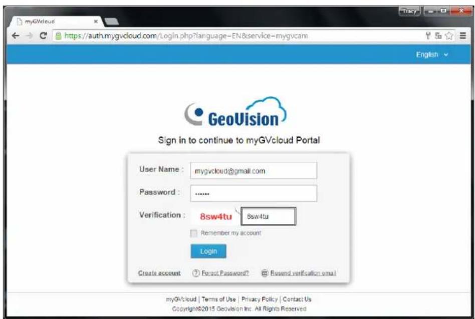
Figure 3-1
- Type the Username (an e-mail address you registered with myGVcloud) and Password of your myGVcloud account.
- Type the Verification code.
- Click Login.
When logging in myGVcloud for the first time, you will be prompted to allow plugin installation. Click to allow installation of Add-on and ActiveX components.
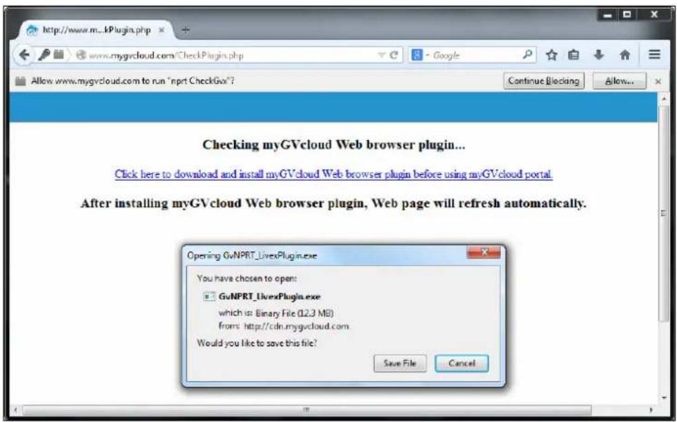
Figure 3-2
Depending on the security setting of your browser, you may need to repeat this process more than one time. For IE users, you may need to change the security settings to install ActiveX. Refer to Appendix A for details.
3.1 The Main Screen
After logging in, you will see the live view of the first camera and a list of all cameras assigned to the myGVcloud account. You can select up to 9 cameras in the Camera List to watch their live views simultaneously.
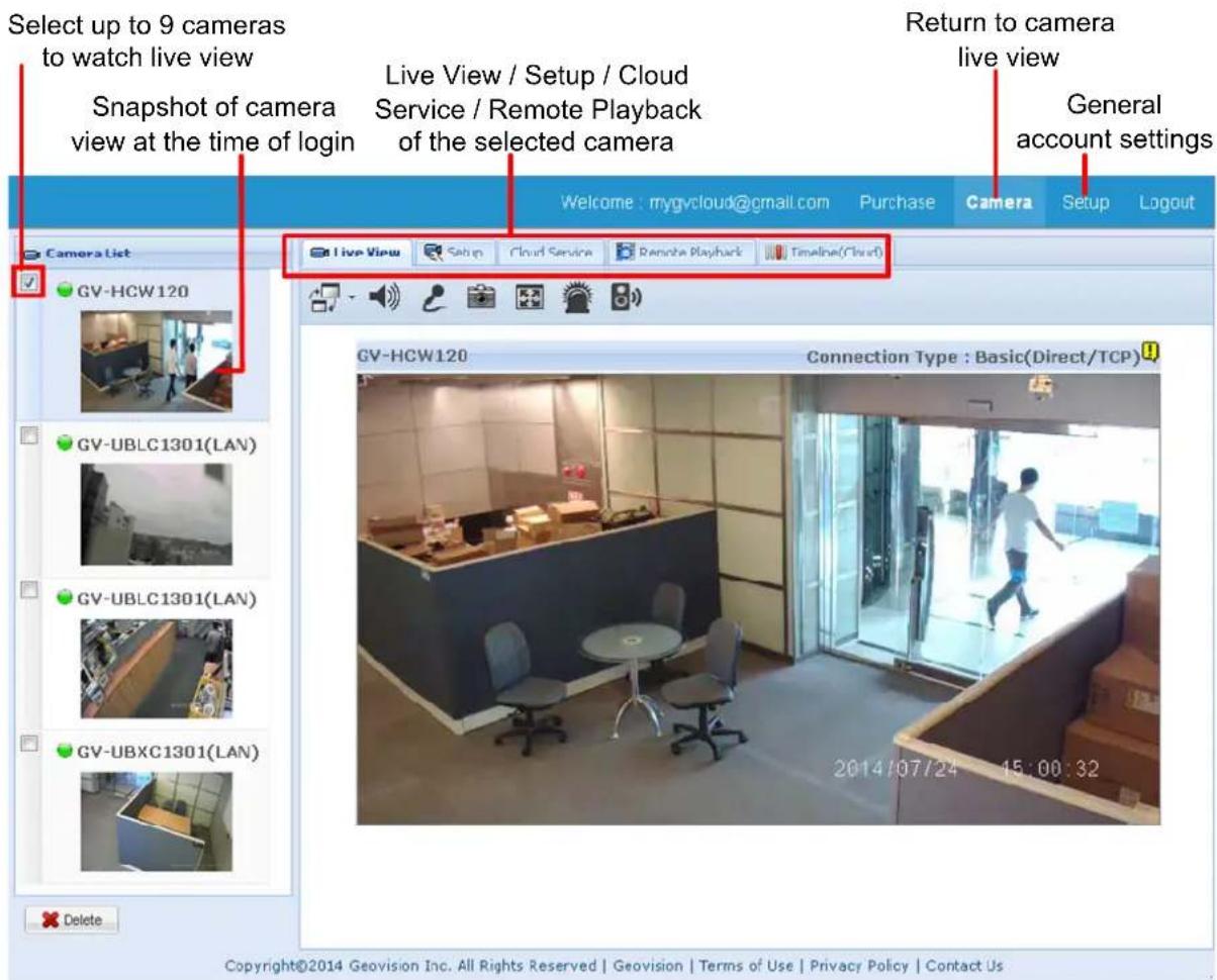
Figure 3-3
3.2 The Live View Window
When accessing the live view, the following window appears.
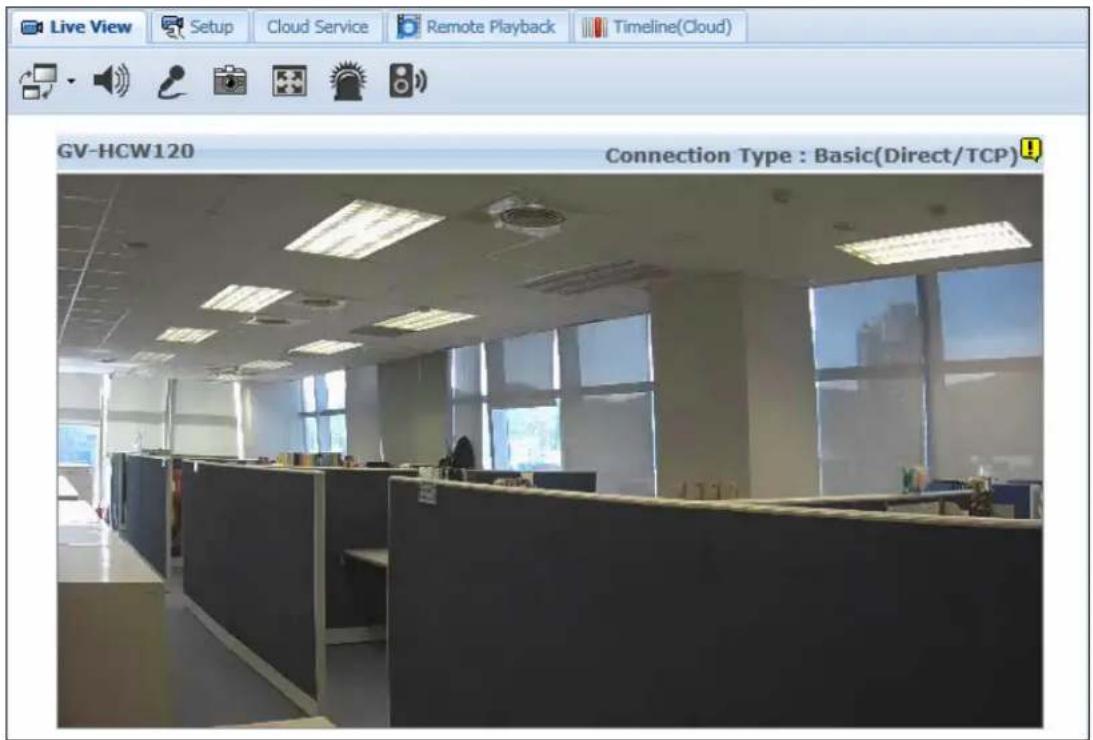
Figure 3-4
| Function Description | ||
 | Video Size | Set the live view resolution to Record Streaming or Preview Streaming. The record resolution can be modified in Camera Setup page (Figure 3-9). The preview resolution can be set in the Web interface of the camera by selecting the Video Setting page of Stream 2 (Figure 6-18). |
 | Audio | Listens to the audio around the camera. This function is not supported for GV-UBLC1301. |
 | Microphone | Talks through the built-in speaker on the camera. This function is not supported for GV-UBLC1301. |
 | Snapshot Takes a snapshot of the live view. | |
 | Full screen Switches to full screen view. | |
 | LED | Click to turn on the alarm LED on the camera and to adjust the brightness. This icon is only available for GV-HCW120. |
 | Alarm Speaker | Click to sound the audio alarm on the camera and adjust the alarm volume. This icon is only available for GV-HCW120. |
Right-click the live view to access additional functions.
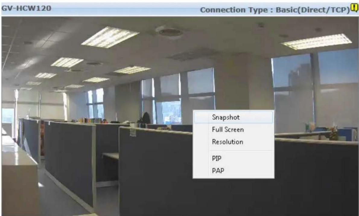
Figure 3-5
■ Snapshot: Saves the current live view image.
■ Full Screen: Switches to full screen view.
■ Resolution: Shows the current resolution in the bottom-right corner.
■ PIP (Picture-in-Picture): Select an area to get a close-up view of the selected area.
■ PAP (Picture-and-Picture): Select up to 7 close-up views by drawing a navigation box on the live view.
For details on PIP and PAP, refer to 6.4.5 Picture-in-Picture and Picture-and-Picture View.
3.3 Camera Settings
Click the Setup tab on the top to modify camera settings such as starting recording, changing resolution and enabling LEDs. Remember to click Save after modifying the settings.

Figure 3-6
Note: The options available in the camera setup page vary depending on the camera model.
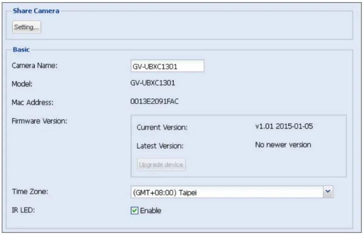
Figure 3-7
[Share Camera] Click Setting to share the cameras assigned to your myGVcloud account to up to 4 other myGVcloud accounts. Type the myGVcloud account and click Invite to send a confirmation email with activation link to the account. After activation, the other myGVcloud account will be able to access the live view of the selected camera. If Allow Video Playback is selected, they will also be able to play back motion events.
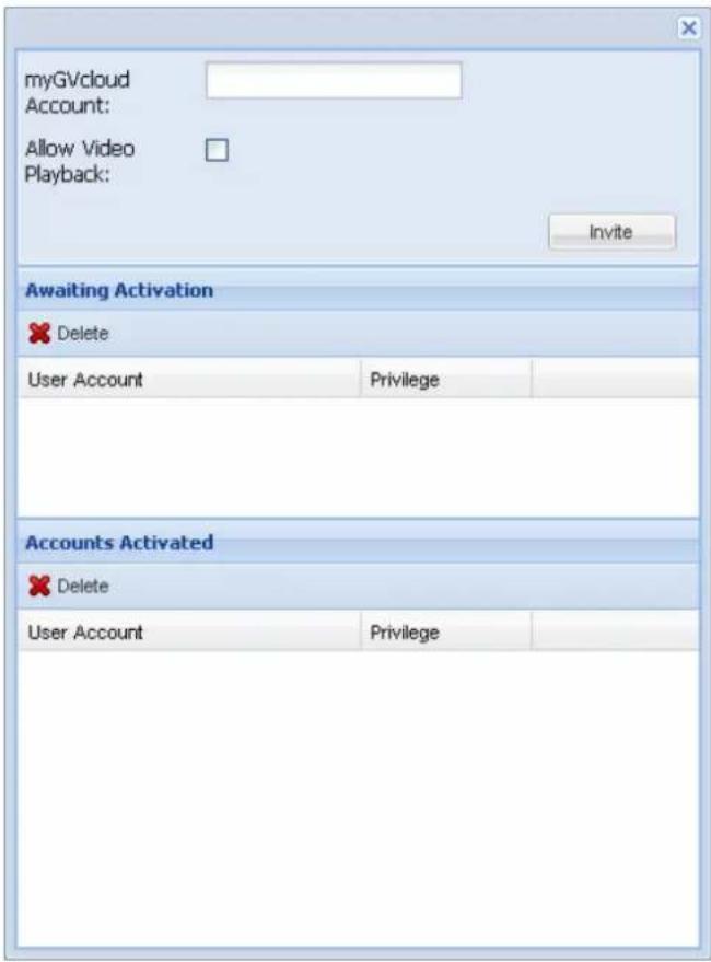
Figure 3-8
Note: If the user was previously logged into a myGVcloud account on the same PC, be sure to log out of the previous account before clicking the activation link. Otherwise, the user will be directed to the previous account instead of the account in the activation link.
[Basic]
■ Camera Name: Change the display name of the camera if needed.
■ Model: Show the camera model.
■ Mac Address: Show the MAC address of the camera.
■ Firmware Version: Show the current firmware version of the camera. You can click Upgrade Device to upgrade to the latest firmware if available.
■ Time Zone: Set the time zone of the camera.
■ IR LED: When enabled, the IR LED on the camera lights up under low lights to allow night vision. This function is not available for GV-HCW Cameras and GV-MFDC Cameras.
■ Status LED: When disabled, the Live View, Recording, Ready and LAN LED on the camera will not light up. This function is only available for GV-HCW Cameras.
■ Alarm LED: When enabled, the Alarm LED on the camera lights up when motion is detected in an environment where the amount of light is insufficient. This function is only available for GV-HCW Cameras.
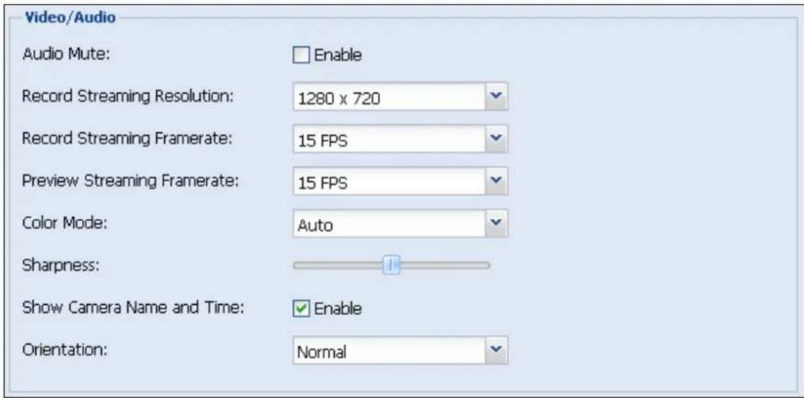
Figure 3-9
[Video / Audio]
■ Audio Mute: Select Enable to exclude audio from the recording. If Audio Mute is enabled, the audio function for live view, recording and YouTube / UStream live streaming will all be disabled. This function is not available for GV-UBLC Cameras.
■ Record Streaming Resolution: Set the recording resolution for the camera. The Large resolution (Stream 1) of the camera will be used.
■ Record Streaming Frame Rate: Set the recording frame rate for the camera.
■ Preview Streaming Frame Rate: Set the live view frame rate for the camera.
■ Color Mode: Select Color mode to watch live view in color or select Mono mode for live view in black and white. When Auto mode is selected, the camera will switch to Mono mode when the amount of light is insufficient.
■ Sharpness: Adjust the sharpness of the camera image. This setting will be applied to both the live view and the recording.
■ Show Camera Name and Time: Shows the camera name and time on the live view and recording when enabled.
■ Orientation: You can adjust the image orientation by selecting Normal, Horizontal Mirror, Vertical Flip or Rotate 180.
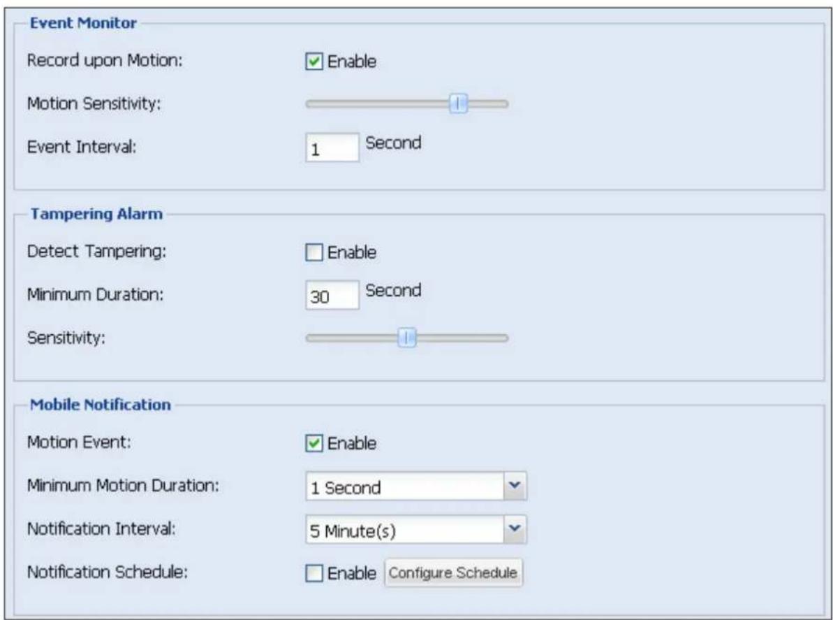
Figure 3-10
[Event Monitor]
■ Record upon Motion: Select Enable to record video upon motion detection. The Large resolution (Stream 1) of the camera will be recorded to the micro SD card. Make sure the SD card is inserted and formatted.
■ Motion Sensitivity: Set the sensitivity level for motion detection. This function is not available for GV-HCW Cameras.
■ Event Interval: Set an interval to limit the frequency of motion recording. For example, if event interval is set to 60 seconds, motion detected within 60 seconds after the first motion event ends will be ignored.
[Tampering Alarm]
■ Detect Tampering: Select Enable to send notifications to mobile devices upon tampering alarm. A tampering alarm can be generated when the camera is moved, covered up, or out of focus. For mobile notification to work, myGVcloud CamApp needs to be installed on the mobile device. See Chapter 5 for details
■ Minimum Duration: Set the minimum duration for which tampering condition must persist for mobile devices to receive tampering alarm. (Max. 60 seconds)
■ Sensitivity: Set the sensitivity level for tampering detection.
[Mobile Notification]
■ Motion Event: Select Enable to send notifications to mobile devices upon motion detection. For this function to work, myGVcloud CamApp needs to be installed on the mobile device. See Chapter 5 for details.
■ Minimum Motion Duration: Set the minimum duration for which motions must persist for mobile devices to receive motion alarm. (Max. 60 seconds)
■ Notification Interval: Set an event interval to limit the frequency of notifications to mobile devices during continuous motion detection. For example, if motion is detected continuously and event interval has been set to 1 minute, notifications will be sent to mobile devices once every minute.
■ Notification Schedule: Click Enable to enable notification to mobile devices only during the scheduled times. Click Configure Schedule and drag across the weekly schedule to highlight where you want mobile notification to be enabled. You can also click Disable at the top and drag on the weekly schedule to disable notification during these time periods.
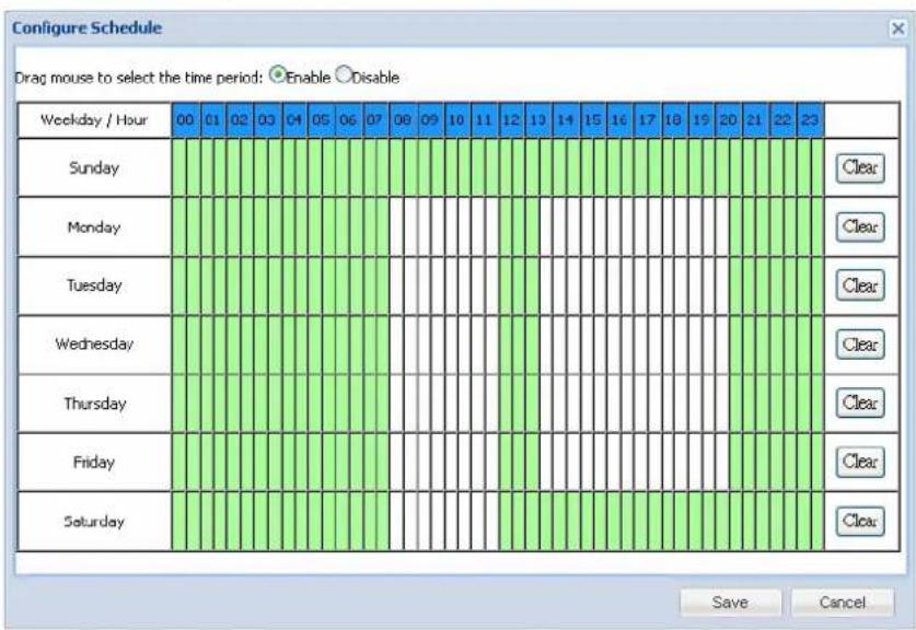
Figure 3-11
Below the Event Monitor section, you can click Show advanced settings to see the storage related settings.
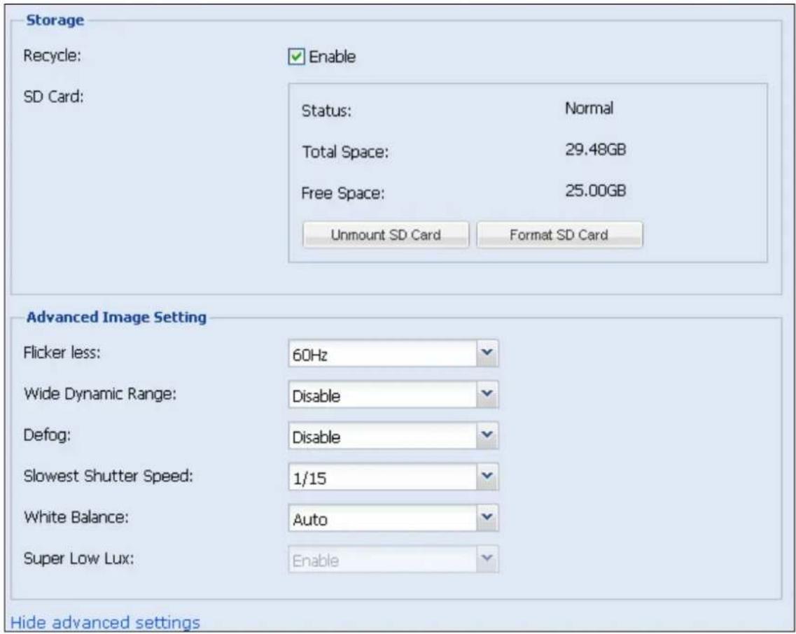
Figure 3-12
[Storage]
■ Recycle: Select Enable to recycle the oldest recordings when the micro SD card becomes full.
■ SD Card: To safely remove the micro SD card, click Unmount SD Card first before removing to prevent data loss. To format the micro SD card, click Format SD Card.
[Advanced Image Setting]
- Flicker less: The camera automatically matches the frequency of your camera's image to the frequency of indoor light sources, e.g. fluorescent lighting. You can also select 50 Hz or 60 Hz manually. If these don't match, faint light and dark bars may appear in your images. Check the power utility to determine which frequency is used.
■ Wide Dynamic Range: Adjusts and generates clear live view when the scene contains very bright and very dark areas at the same time. Select Auto (Strong) to bring out details in the darks areas of the scene, select Auto (Weak) to bring out less detail in the dark area and at the same time keep the bright areas from overexposure, or select Auto (Normal) for a balanced effect.
■ Defog: Select Auto to automatically enhance the visibility of images.
■ Slowest Shutter Speed: Shutter speed controls the amount of the lights enters the image sensor and directly impacts the quality of image presentation. A slow shutter speed allows higher light exposure that creates a brighter overall image by blurring moving objects and bringing out background details, and a faster shutter speed lowers color and image clarity in order to capture motions.
■ White Balance: The camera automatically adjusts the color to be closest to the image you are viewing. You can choose one of the four presets: Auto, Outdoor, Fluorescent, and Tungsten Lamp.
■ Super Low Lux: Select Enable for the camera to automatically enhance the live view under insufficient light. The default setting is Enable. This function is only available for GV-MFDC Cameras.
3.4 Cloud Service
To enable Cloud Service for the selected camera, click the Cloud Service tab.
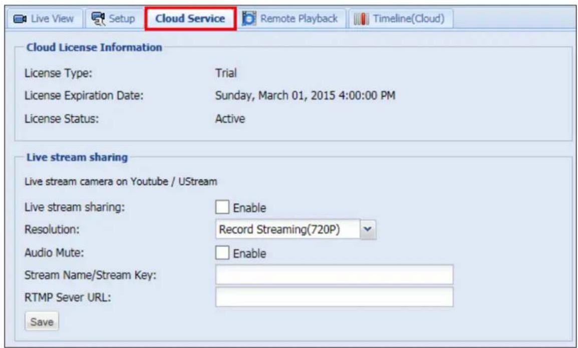
Figure 3-13
[Cloud License Information] Shows information of the cloud license acquired for this camera. GeoVision's Cloud Service allows you to store recordings in the cloud storage. To manage cloud license, click Purchase in the top-right corner.
[Live Stream Sharing] You can live stream the camera image on YouTube or UStream. You will need to have an account for YouTube or UStream and complete the required settings to obtain the stream name / key and RTMP server URL. For details, refer to Appendix C. Setting Live Streaming on YouTube or UStream.
■ Live stream sharing: Select Enable to live stream the camera live view.
■ Resolution: Select the resolution of the live stream. The resolution selected must be equal or larger than the resolution selected in YouTube or UStream.
■ Audio Mute: Select Enable to mute the audio of the live stream.
■ Stream Name / Stream Key: Paste the Stream Name / Stream Key obtained from the setup page of YouTube or UStream. Refer to Appendix C for details.
■ RTMP Server URL: Paste the RTMP Server URL obtained from the setup page of YouTube or UStream. Refer to Appendix C for details.
Note:
- When streaming camera live view, it is recommended not to play music close to the camera to avoid copyright infringement. You can also select the Audio Mute function to avoid this issue.
- To stream live view in real time, it is recommended to have a minimum upload bandwidth of 3 Mbps.
3.5 Remote Playback
To look up and play back recorded videos of the camera selected, click the Remote Playback tab. You can select recorded videos stored in the micro SD card or in the cloud storage.
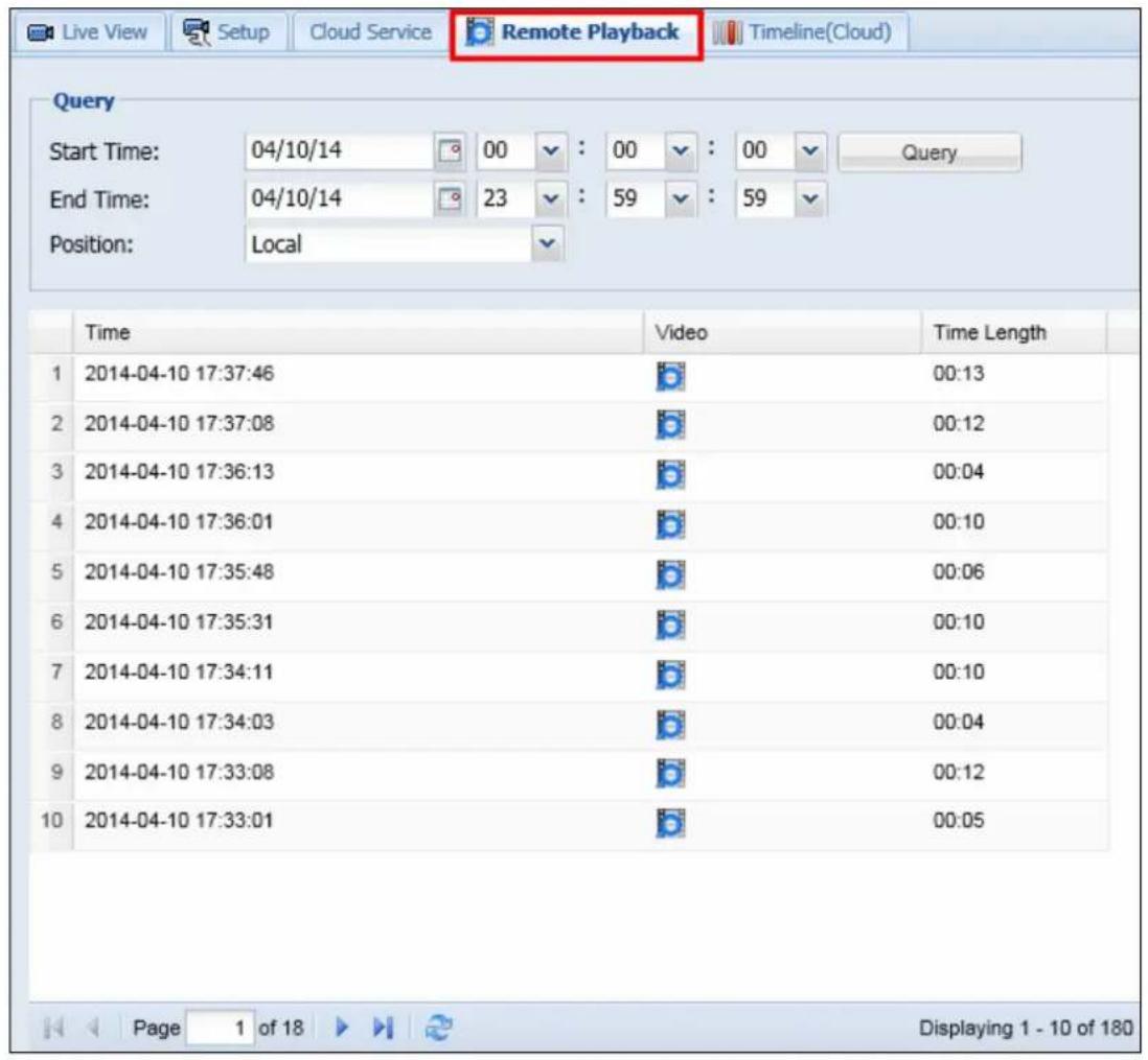
Figure 3-14
- Under Query, select a Start Time and an End Time.
- Next to Position, select whether to retrieve events from the Local SD card or from Cloud storage.
- Click Query. The events recorded within the Start Time and End Time are displayed.
- To play back video, click the Video button ☐. If your PC does not have an mp4 compatible media player, you can right-click the icon and save the selected event file instead.
Note:
- You can also click the Timeline (Cloud) tab to locate events saved in cloud storage from a timeline. See 3.6 Timeline (Cloud) for details.
- To change the default media player for event playback, refer to Appendix B for more details.
3.6 Timeline (Cloud)
To look up and play back recorded videos stored in Cloud Storage, click the Timeline (Cloud) tab.
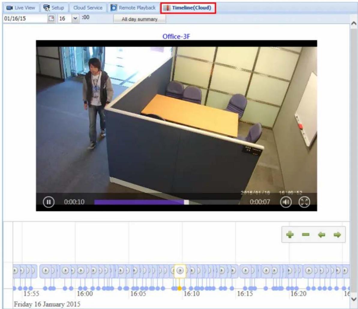
Figure 3-15
Videos recorded during the selected time period will be displayed in a timeline. You can select a time, or click the All day summary button to see when events are recorded throughout the selected day. Click the arrow button on the timeline to play back recorded videos.
3.7 General Account Settings
To modify the password of myGVcloud account or to set e-mail notification for camera disconnection, click Setup at the top-right corner.
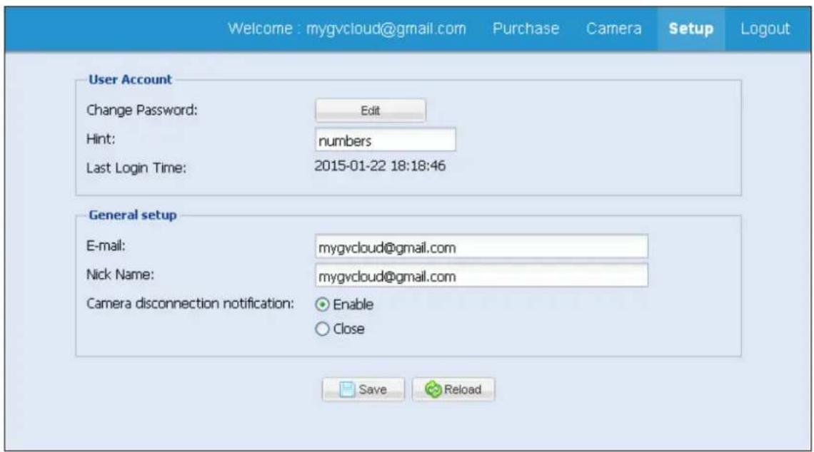
Figure 3-17
[User Account]
■ Change Password: Click Edit to change the password of your myGVcloud account.
■ Hint: Modify the password hint if needed.
■ Last Login Time: Shows the time this account logged into myGVcloud Portal.
[General Setup]
■ E-mail: Set the e-mail to receive notification upon camera disconnection.
■ Nick Name: Change the account display name at the top-right corner.
■ Camera disconnection notification: Select Enable to send e-mail notification upon camera disconnection.
Click the Save button after modifying the settings.
Chapter 4 myGVcloud CamViewer
myGVcloud CamViewer is a software you can install on your PC to watch live view, play back recordings and receive pop-up notifications upon motion.
Download myGVcloud CamViewer from the link below, unzip the downloaded file, and run myGVcloudCamViewer_Install.exe.
http://pd.geovision.tw/neo/myGVcloud/Program/myGVcloud_CamViewer.zip

myGVcloud
On your PC desktop, double-click the myGVcloud CamViewer icon CamViewer, type the login information of your myGVcloud account and click OK. The camera list and the event icon appear.
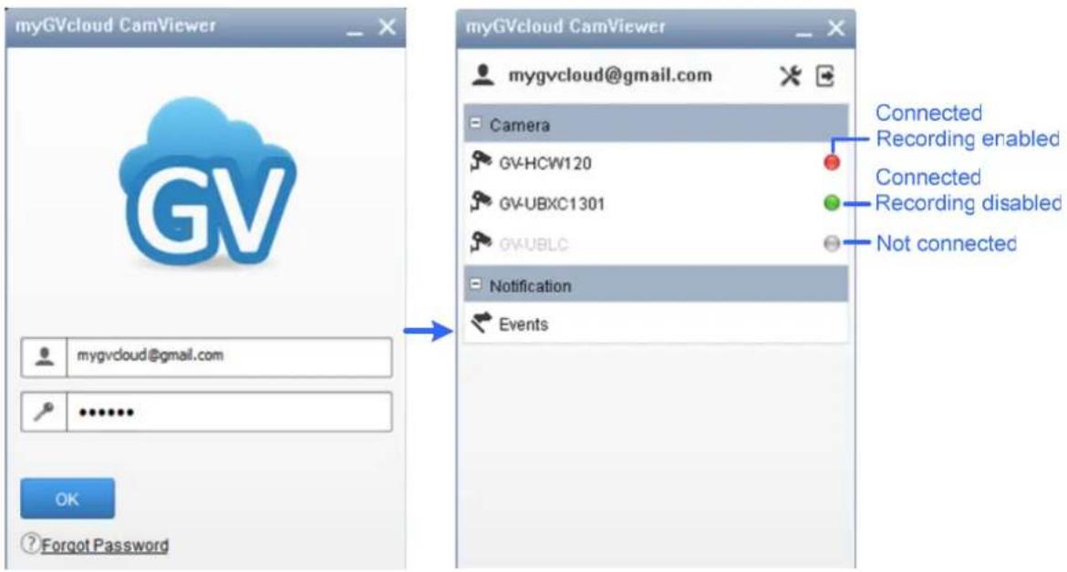
Figure 4-1
4.1 Accessing Live View and Recorded Videos
- In the camera list, click a camera to access its live view. This window appears.
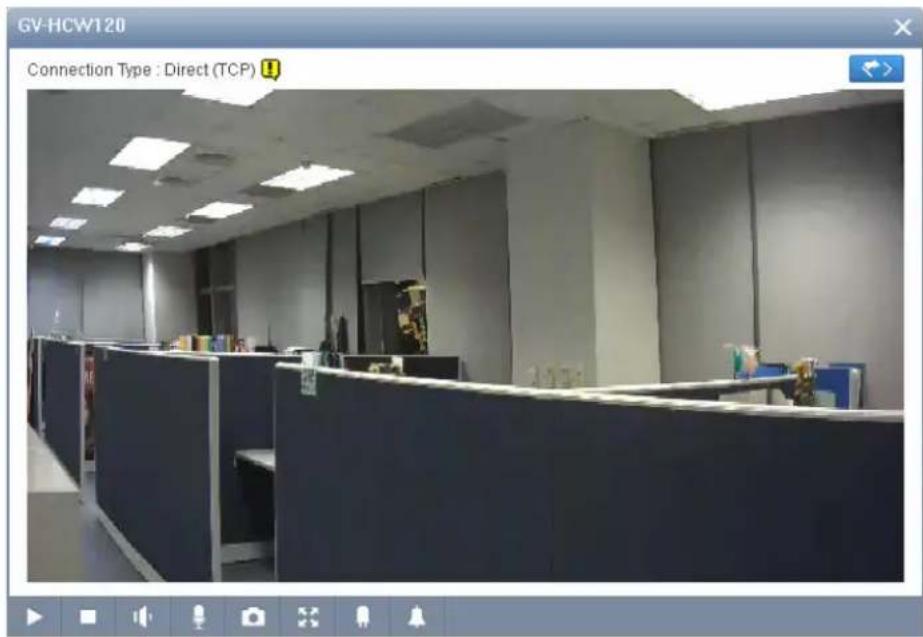
Figure 4-2
- To look up events recorded upon motion detection, click the Event button. The event list appears on the right.
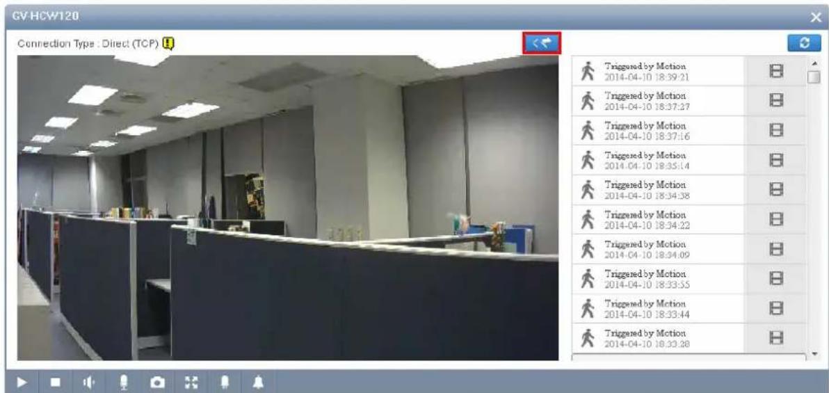
Figure 4-3
- To play back the recorded videos, click the Event button on the right. If your PC does not have an mp4 compatible media player, you can download the selected event file instead.
In the main screen of myGVcloud CamViewer, you can also look up recorded events from all connected cameras by clicking Events under Notification.
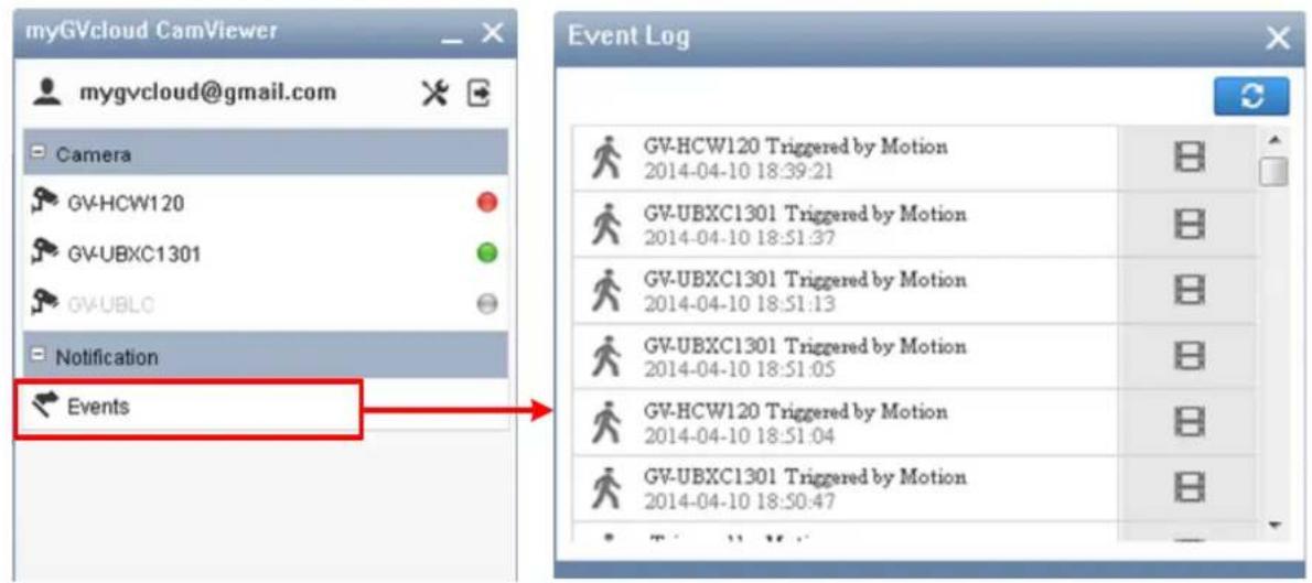
Figure 4-4
4.2 General Setting
- To access the general settings of myGVcloud CamViewer, click the Settings ✗ button.
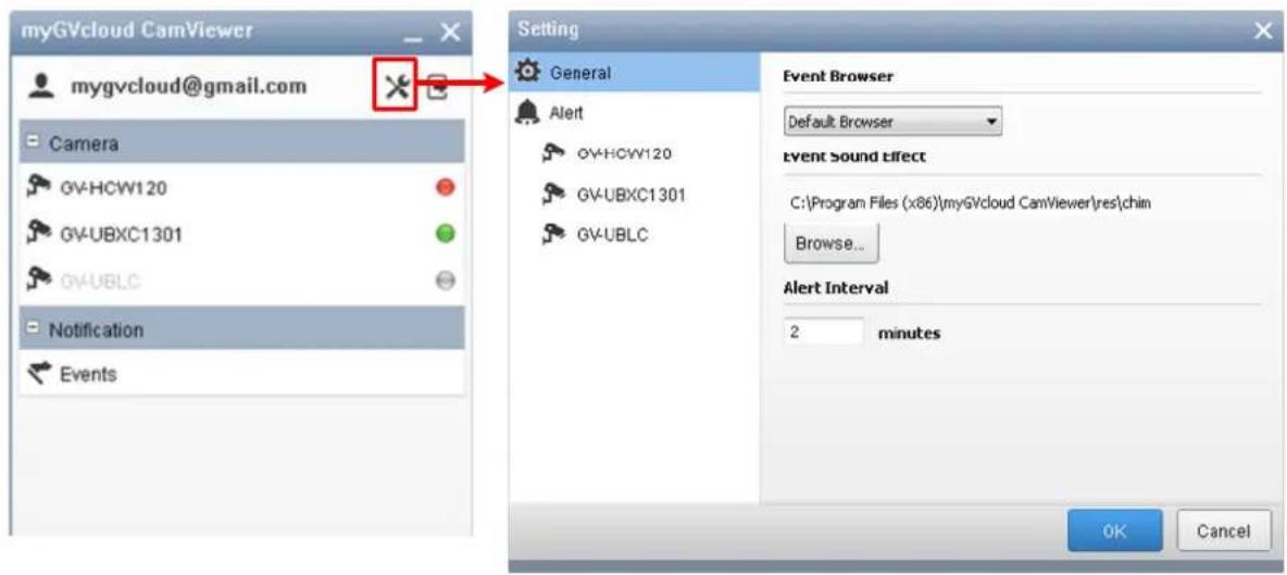
Figure 4-5
- Under the General tab on the left, the following options are available.
■ Event Browser: Set the type of browser to use for playing back recorded events.
■ Event Sound Effect: You can change the alert sound effect by clicking the Browse button and select another sound file from your PC.
■ Alert Interval: Set the minimum time interval between each alert notification in minutes. The minimum alert interval is 1 minute.
- Under the Alert tab, select a camera to enable or disable the popup notification upon motion detection events.
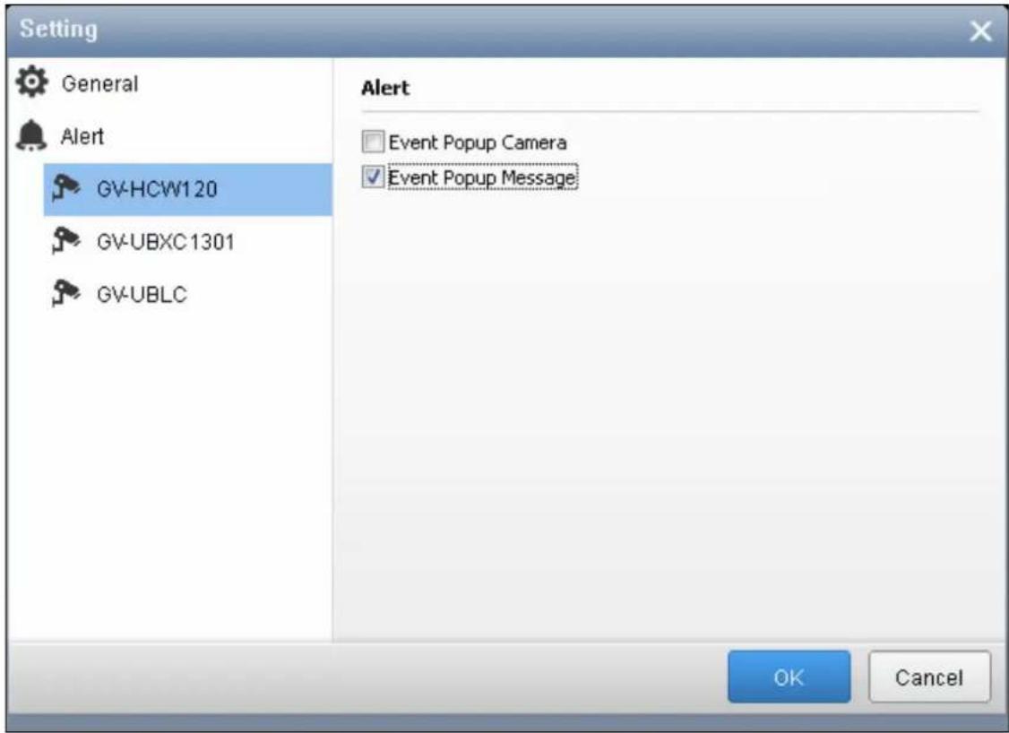
Figure 4-6
■ Event Popup Camera: The camera live view will pop up upon events.
■ Event Popup Message: An alert message will pop up in the bottom-right corner of the screen upon events.
- Click OK to apply the settings.
Chapter 5 myGVcloud CamApp
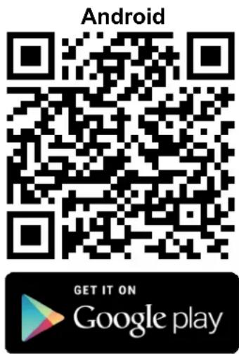
You can access your GV-Cloud Camera from Android or iOS mobile devices. Search for myGVcloud in Google Play or Apple Store or scan the QR codes below. Next, install myGVcloud CamApp on your mobile device.
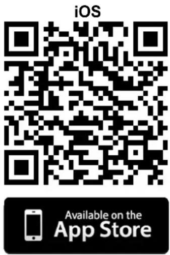
Supported Operating Systems:
- Android version 4.0 or later
- iOS version 7.0 or later
5.1 Logging In myGVcloud Account
Log into your myGVcloud account to access the cameras registered to the account.

- Tap the myGVcloud CamApp icon on the desktop of your mobile device.
- Type the ID and password of your myGVcloud account.
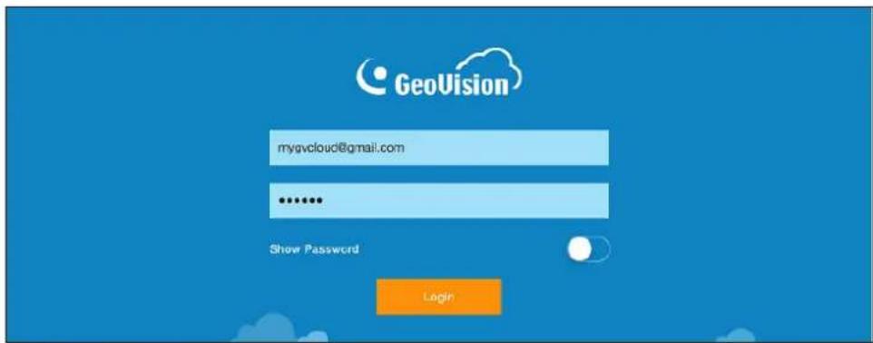
Figure 5-1
- Tap Login. The cameras associated with the myGVcloud account are listed in the Camera List on the left.
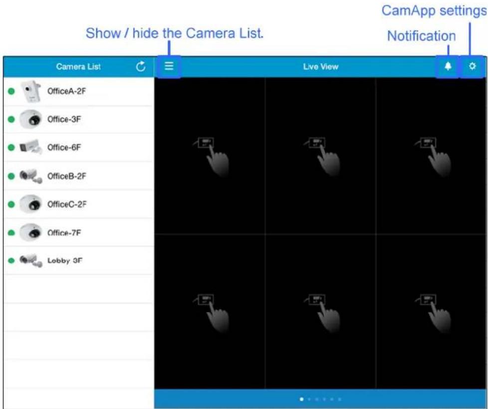
Figure 5-2
5.2 Configuring the Camera Settings
After logging into the myGVcloud account, cameras associated with the account will be listed in the Device List. You can access the camera live view and configure camera settings.
- In the Camera List, tap a camera to see its setting page.
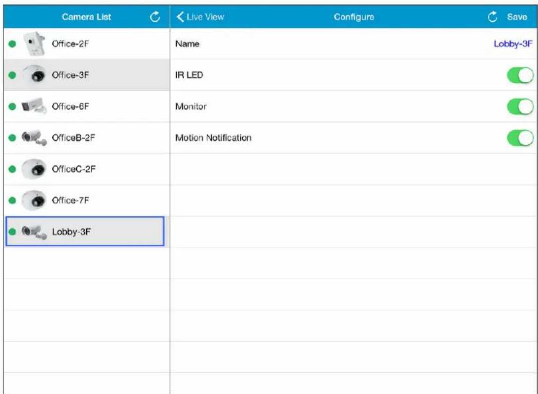
Figure 5-3
- You can change the current settings of the camera. The options available vary for different camera models.
■ Name: Tap the camera name to change the name if needed.
■ Alarm LED: Turn on or off the alarm LED on the camera upon motion detection. This option is only available for GV-HCW Cameras.
■ IR LED: Turn on or off the IR LED for night vision. This option is only available for GV-UBLC / UBXC Cameras.
■ Monitor: Start or stop recording the camera.
■ Motion Notification: Turn on or off notification of motion events from this camera. Note that the notification setting will only apply to your current mobile device.
- Tap Save.
5.3 Accessing Camera Live View
To access camera live view, drag the camera from the Camera List to the live view grid. To disconnect a live view, tap and hold the live view grid and drag the live view into the trash can icon.
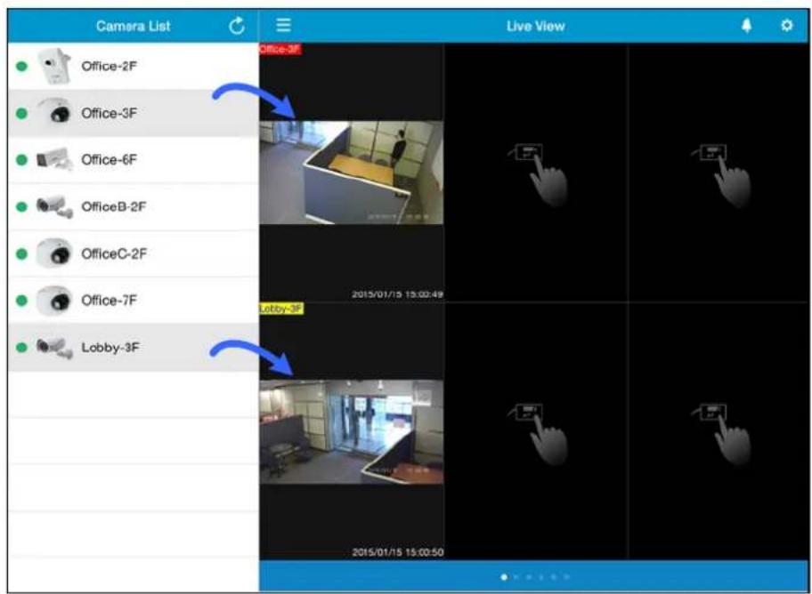
Figure 5-4
Tap the live view grid to see the live view in full screen and to access the following functions.
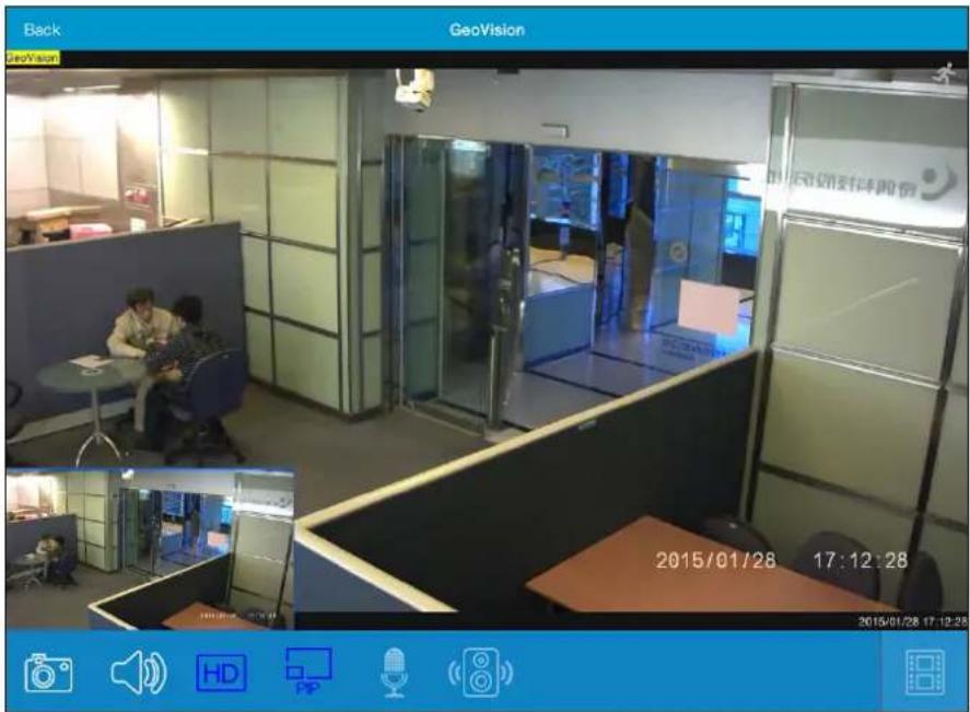
Figure 5-5
| Icon Name Function | ||
 | Motion Detection | The icon becomes red when motion is detected. |
 | Snapshot | Captures and saves the current live view image in the mobile device. |
 | Speaker Allows you to listen to sounds from the surveillance site. | |
 | High Definition | Switches to stream 1 (higher resolution). By default, stream 2 (lower resolution) is connected. |
 | PIP | Shows a picture-in-picture view. If you pinch the main live view to zoom in, a navigation box will appear in the PIP window to indicate the zoomed in region. You can then slide the navigation box around to see closed-up views of different parts of the live view. This function is enabled by default. |
 | Microphone | Enables the microphone, allowing you to broadcast sounds to the surveillance site. |
 | Alarm | Click to sound the audio alarm in the camera. You can adjust the alarm volume. This option is only available for GV-HCW Cameras. |
 | Playback | Plays back recorded videos. For details, see Playing Back Recordings later in this chapter. |
 | Hardware Decode | Enables GPU decoding to lower CPU loading and increase the smoothness of live view. Note this function is only supported by some Android mobile devices. |
5.4 Playing Back Recordings
-
To play back recordings of a camera, tap the Playback icon from the live view page. The recorded videos are listed.
-
Tap an entry to see a snapshot of the video. You can also tap the calendar icon in the top-right corner to select a different date.
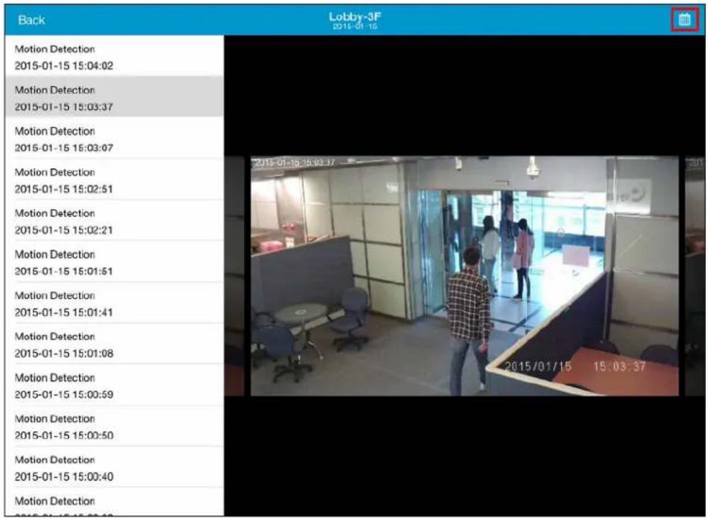
Figure 5-6
- Tap the snapshot to start play back the video.
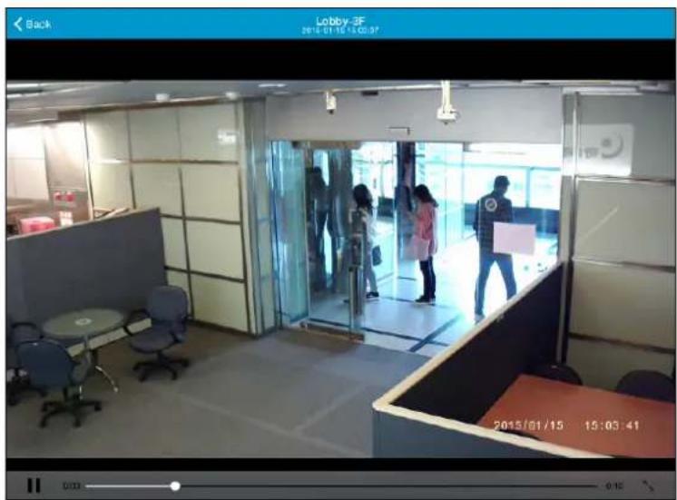
Figure 5-7
5.5 Notification
To see the list of motion and system events from all connected cameras, tap the Notification icon 🙏 in the top-right corner of the live view page.
| Device List | All Devices Delete All Close | |||
| All Devices | 37 | All | System | Unread |
| GV-HCW120 | 15 | GV-HCW120 Motion detection event 2015-01-28 16:58:11 | ||
| GV-UBLC1301 | 12 | GV-UBLC1301 Motion detection event 2015-01-28 16:58:09 | ||
| GV-UBXC1301 | 11 | GV-UBXC1301 Motion detection event 2015-01-28 16:58:07 | ||
| GV-MFDC1501 | 0 | GV-HCW120 Motion detection event 2015-01-28 16:58:05 | ||
| GV-UBXC1301 Motion detection event 2015-01-28 16:57:49 | ||||
| GV-UBLC1301 Motion detection event 2015-01-28 16:57:47 | ||||
| GV-HCW120 Motion detection event 2015-01-28 16:57:44 | ||||
| GV-UBLC1301 Motion detection event 2015-01-28 16:57:22 | ||||
Figure 5-8
- Under the Device List, tap All Devices to see events from all cameras or select a camera.
- On the right side, the notifications are separated into three categories.
■ All: Includes both motion events and system events.
■ System: Includes system events such as tampering alarm, camera disconnection and SD card issues.
■ Unread: Includes all unread events.
- You can slide on an event toward the left to delete it or tap Delete All at the top-right corner to clear all events.
5.6 Configure myGVcloud CamApp Settings
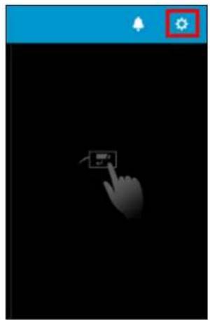
To configure settings of myGVcloud CamApp, tap the Setting icon on the main page.
natural_image
Hand cursor clicking a button on a black background, with a blue control panel and a red gear icon in the corner (no text or symbols)![Settings Done LOGIN ACCOUNT E-Mail mygvcloud@gmail.com Logout LIVE VIEW Show Device Name Show Device Time Keep Image Ratio Icon Size Extra Large > SYSTEM SETTING Disable Screen Off VERSION (V2.0) [D127Y15]](/content/2026/06/1146382/images/3be0aed350c720b9920ea9f69a57af3984f2df5c536de4eea2ca4336dc23e879.jpg)
Figure 5-9
[Login Account]
■ Logout: Logs out of the myGVcloud account.
[Live View]
■ Show Device Name: Displays device name on live view.
■ Show Device Time: Displays device name on live view.
- Keep Image Ratio: Displays the live view in the device's original image ratio.
■ Icon Size: Adjusts the size of the icons in live view.
[System Setting]
■ Disable Screen Off: Turns off sleep mode of the mobile device when myGVcloud CamApp is running. This function is disabled by default.
Chapter 6 Camera Web Interface
The Camera Web Interface allows you to access the GV-Cloud Camera without registering for the myGVcloud Portal. You can directly access the Camera Web interface for monitoring configuration using a Web browser.
6.1 Logging in the Camera's Web Interface
Once installed, your GV-Cloud Camera is accessible through the network. To check the IP address of the camera, you need to run the myGVcloud CamWizard, which will scan for all the GV-Cloud Cameras under the same LAN and display the IP addresses of the detected cameras. To access your surveillance images, follow the steps below:
- Run the myGVcloud Setup Wizard to find the IP address of the camera.
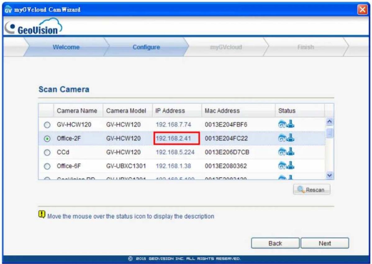
Figure 6-1
- Click the IP address of the camera. This login page appears. Alternatively, manually type the IP address in your Web browser.
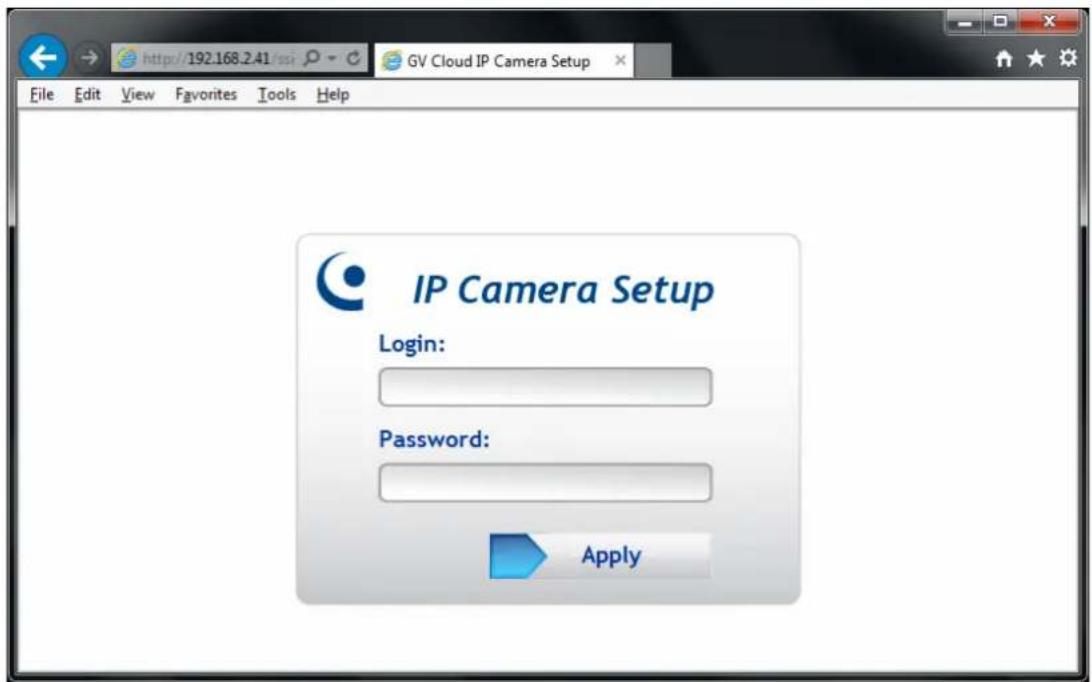
Figure 6-2
- Enter the login name and password. The default login name and password for Administrator are admin.
- Click Apply to log into the Web page.
Note:
- To enable the updating of images in Internet Explorer, you must set your browser to allow ActiveX Controls and perform a once-only installation of GeoVision's ActiveX component onto your computer. For details, see Appendix A.
- To change the default login name and password, see 6.9.2 User Account.
IMPORTANT: The login information of the camera's Web interface is different from your myGVcloud Portal account. The login information must match the username and password configured in the myGVcloud Setup Wizard. For details, see Figure 2-5 in 2.1 Setting Up the Camera.
6.2 List of Menu Option
Seven categories of configurations are involved in the system configuration: Event List, Live View, Video Settings, Events and Alerts, Monitoring, Network and Management. Find the topic of interest by referring to the section number prefixed to each option.
| 6.3 Event List | |
| 6.4 Live View | 6.4.1 The Live View Window6.4.2 The Control Panel of the Live View Window6.4.3 Snapshot of Live Video6.4.4 Video Recording6.4.5 Picture-in-Picture and Picture-and-Picture View6.4.6 Alarm Notification6.4.7 Video and Audio Configuration6.4.8 Remote Configuration6.4.9 Camera Name Display6.4.10 Image Enhancement6.4.11 Digital PTZ |
| 6.5 Video Settings | 6.5.1 Streaming 1 / 26.5.2 OSD |
| 6.6 Events and Alerts | 6.6.1 Notification6.6.2 myGVcloud |
| 6.7 Monitoring | 6.7.1 Monitoring6.7.2 Storage Settings |
| 6.8 Network | 6.8.1 Wireless6.8.2 Status6.8.3 LAN6.8.4 Advanced TCP/IP |
| 6.9 Management | 6.9.1 Date and Time Settings6.9.2 User Account6.9.3 Tools6.9.4 Language |
6.3 Event List
The GV-Cloud Camera records video and audio directly to the memory card. The Event List provides a list of recordings existing in the memory card. You can see the event list only when a memory card with recordings is inserted to the camera.
When logging into the Web page of your camera, a list of motion detection events appears.
| Event Type | Camera | Video Clip | Date | Time |
| Motion Detection | 1 | 2013-08-01 | 17:51:55 | |
| Motion Detection | 1 | 2013-08-01 | 17:51:45 | |
| Motion Detection | 1 | 2013-08-01 | 17:50:37 | |
| Motion Detection | 1 | 2013-08-01 | 17:50:28 | |
| Motion Detection | 1 | 2013-08-01 | 17:50:18 | |
| Motion Detection | 1 | 2013-08-01 | 17:49:26 | |
| Motion Detection | 1 | 2013-08-01 | 17:49:16 | |
| Motion Detection | 1 | 2013-08-01 | 17:48:27 | |
| Motion Detection | 1 | 2013-08-01 | 17:48.17 | |
| Motion Detection | 1 | 2013-08-01 | 17:48.08 | |
| Motion Detection | 1 | 2013-08-01 | 17:47:58 | |
| Motion Detection | 1 | 2013-08-01 | 17:47:05 | |
| Motion Detection | 1 | 2013-08-01 | 17:46:55 | |
| Motion Detection | 1 | 2013-08-01 | 17:46:43 | |
| Motion Detection | 1 | 2013-08-01 | 17:46:33 | |
| Motion Detection | 1 | 2013-08-01 | 17:46:18 | |
| Motion Detection | 1 | 2013-08-01 | 17:46:09 |
Figure 6-3
To play back video, click the Video Clip button. The read event will be shown in black in the list.
IMPORTANT: The video can only be played with QuickTime Player.
6.4 Live View
The camera can simultaneously process one video source in two different codec and resolutions. The dual-stream design benefits for lower bandwidth environment, allowing Stream 2 set with lower resolution and codec for live streaming, and Stream 1 set with highest resolution and codec H.264 for best recording quality.
6.4.1 The Live View Window
In different browsers, the live view window is different.
Internet Explorer
When accessing the live view using Internet Explorer, the following window appears.
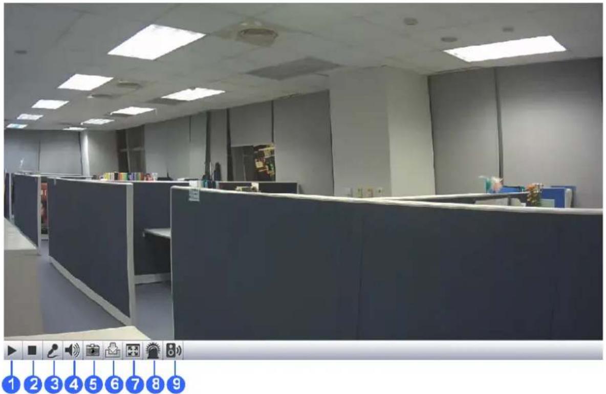
natural_image
Interior view of a modern office cubicle with ceiling lights and no visible text or symbols on the main surfaces.Figure 6-4
| No. | Name Function | |
| 1 | Play Plays live video. | |
| 2 | Stop Stops playing video. | |
| 3 | Microphone | Listens to the audio around the camera. This function is not available for GV-UBLC Cameras. |
| 4 | Speaker | Talks through the built-in speaker on the camera. This function is not available for GV-UBLC Cameras. |
| 5 | Snapshot | Takes a snapshot of live video.--- See 6.4.3 Snapshot of Live Video. |
| 6 | File Save | Records live video to the local computer.--- See 6.4.4 Video Recording. |
| 7 | Full Screen Switches | to full screen view. |
| 8 | LED Control | Click to turn the Alarm LED on and/or adjust the brightness sensitivity. This function is only available for GV-HCW Cameras. |
| 9 | Alarm Speaker | Click to sound the alarm and/or adjust its volume. The alarm lasts 10 seconds each time. The volume level ranges from 1 (default) to 100. This function is only available for GV-HCW Cameras. |
You can right-click the image to have these options: Snapshot, Full Screen, Resolution, PIP, PAP. --- See 6.4.5 Picture-in-Picture and Picture-and-Picture View for PIP and PAP views.
Non-IE Browsers
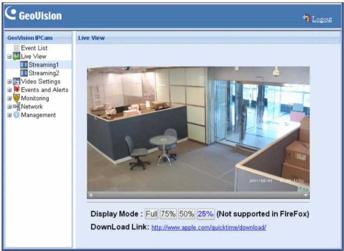
When accessing the live view using Google Chrome, Firefox or Safari, this window appears. Note the function of Two-Way Audio is not supported on non-IE browsers.
F i g u r e
Note: For non-IE browsers, it is required to install the QuickTime player to access the live view.
6.4.3 Snapshot of Live Video
To take a snapshot of live video, follow these steps:
- Click the Snapshot button (No. 5, Figure 6-4). The Save As dialog box appears.
- Specify Save in, type the File name, and select JPEG or BMP as Save as type.
- Adjust the image Quality if needed.
- Click the Save button to save the image in the local computer.
6.4.4 Video Recording
You can record live video for a certain period of time to your local computer.
- Click the File Save button (No. 6, Figure 6-4). The Save As dialog box appears.
- Specify Save in, type the File name, and move the Time Period slider to specify the time length of the video clip from 1 to 5 minutes.
- Click the Save button to start recording.
- To stop recording, click the Stop button (No. 2, Figure 6-4).
6.4.5 Picture-in-Picture and Picture-and-Picture View
The Live View window provides two types of close-up views: Picture-in-Picture (PIP) and Picture-and Picture (PAP). The two views are useful to provide clear and detailed images of the surveillance area.
Picture-in-Picture View
With the Picture in Picture (PIP) view, you can crop the video to get a close-up view or zoom in on the video.
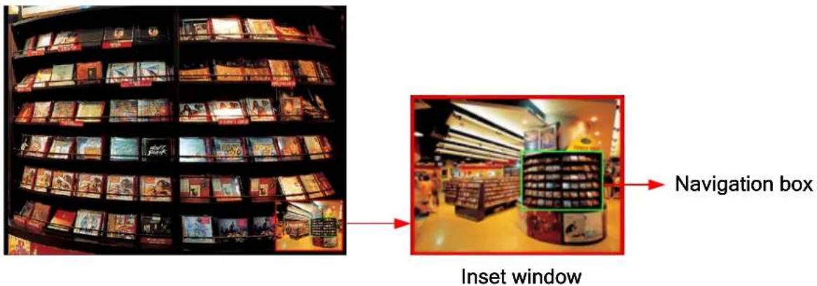
Figure 6-6
- Right-click the live view and select PIP. An inset window appears.
- Click the insert window. A navigation box appears.
- Move the navigation box around in the inset window to have a close-up view of the selected area.
- To adjust the navigation box size, move the cursor to any of the box corners, and enlarge or diminish the box.
- To exit the PIP view, right-click the image and click PIP again.
Picture-and-Picture View
With the Picture and Picture (PAP) view, you can create a split video effect with multiple close-up views on the image. A total of 7 close-up views can be defined.
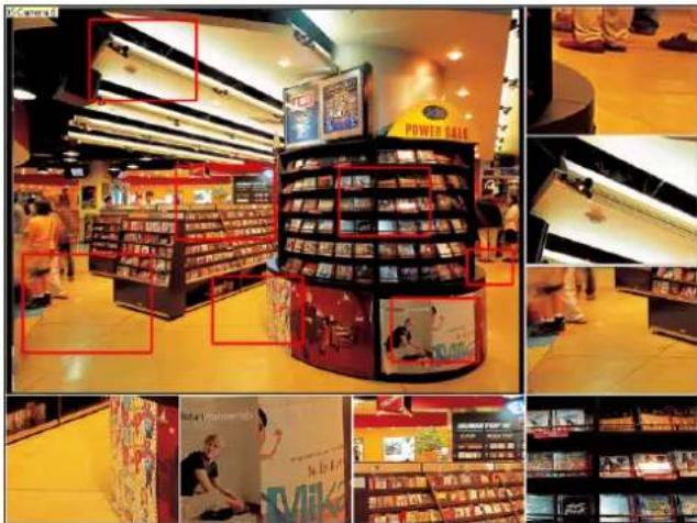
Figure 6-7
-
Right-click the live view and select PAP. A row of three inset windows appears at the bottom.
-
Draw a navigation box on the image, and this selected area is immediately reflected in one inset window. Up to seven navigation boxes can be drawn on the image.
-
To adjust a navigation box size, move the cursor to any of the box corners, and enlarge or diminish the box.
-
To move a navigation box to another area on the image, drag it to that area.
-
To exit the PAP view, right-click the image and click PAP again.
6.5 Video Settings
6.5.1 Streaming 1 / 2
Two setting Web pages Streaming 1 and Streaming 2 are provided for separate setup. For Streaming 2, you can only configure resolution and frame rate.
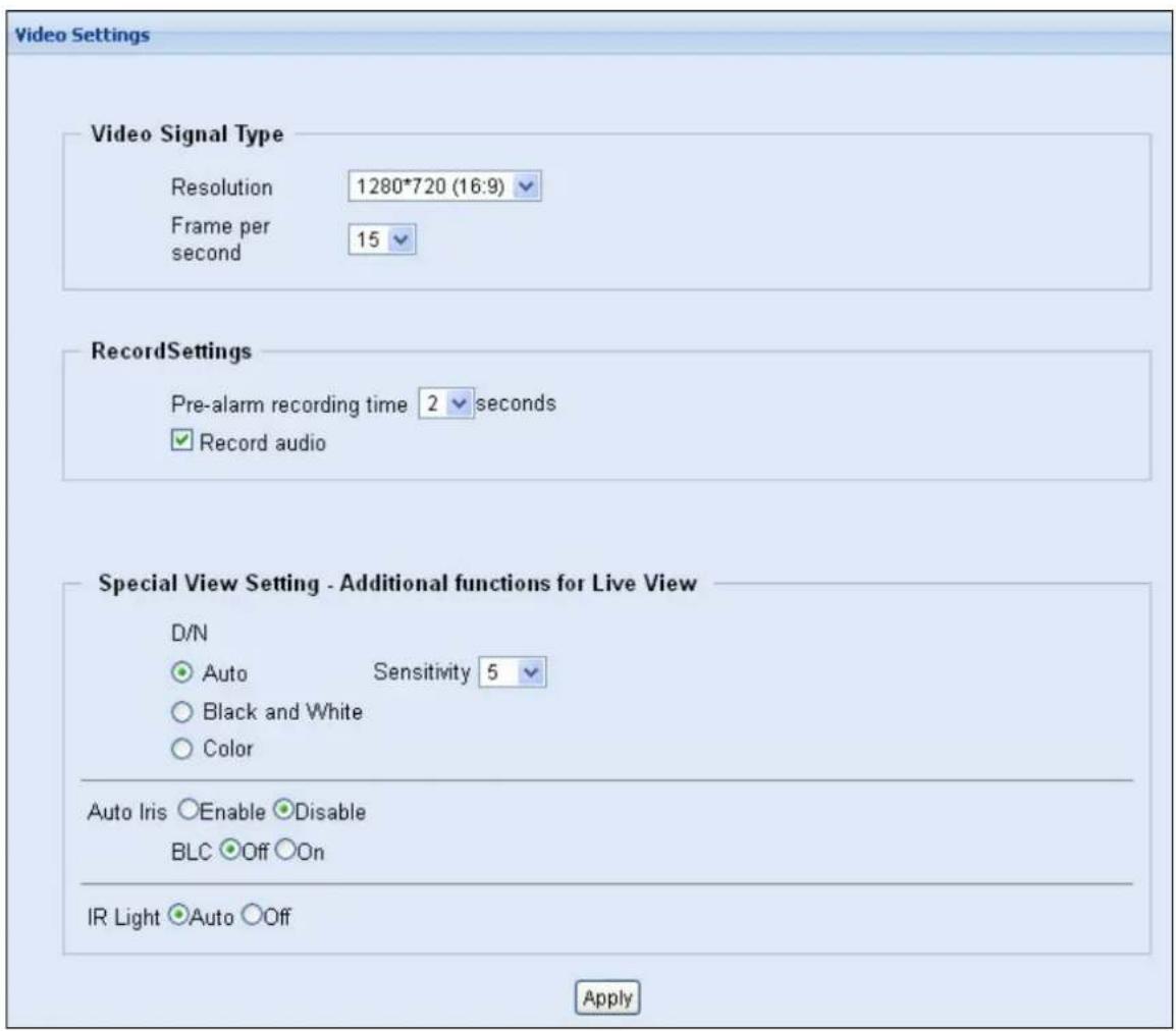
Figure 6-8
[Video Signal Type] Select the video format, resolution and frame rate.
■ Resolution: Select the resolution for the stream selected. (Streaming 1 or Streaming 2)
■ Frame per second: Set up the frame rate of the stream selected.
[Record Settings] The alarm settings allow you to capture images before and/or after the motion events happen.
■ Pre-alarm recording time: Activate video recording before an event occurs. Set the recording time to 1 or 2 seconds. The recording is saved in the buffer of the camera.
■ Record audio: Activate audio recording when an event occurs. Audio recording is enabled by default. This function is not available for GV-UBLC Cameras.
[Special View Setting – Additional functions for Live View]
■ D/N: The default setting is Auto mode with a sensitivity level of 5.
- Auto: Select Auto for the camera to detect the amount of light present and automatically switch to monochrome in a poorly-lit scene. Move the slider to adjust the sensitivity level of day-night mode switch from 0 to 10. The higher the sensitivity value, the more sensitive the switch is from day mode to night mode.
● Black and White: Select this option for the live view to be in monochrome.
● Color: Select this option for the live view to be in color.
■ Auto Iris: Enable the auto iris function when the scene appears fuzzy and the Flicker Less function does not help to improve the situation. This function is not supported in GV-HCW and GV-MFDC Cameras.
■ BLC: Select On to enable Backlight Compensation (BLC). This function is used to adjust the color intensity of scenes with strong light at the background.
■ IR Light: When IR Light is set to Auto, the IR light will automatically turn on when the camera is in Black and White mode and when the camera switch to night mode under Auto mode.
6.5.2 OSD
You can set up the on-screen display for Streaming 1 and Streaming 2 respectively in this section.
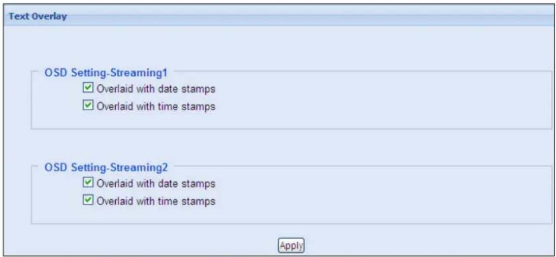
Figure 6-9
■ Overlaid with date stamps: Include data stamps on live and recorded videos.
■ Overlaid with time stamps: Include time stamps on live and recorded videos.
6.6 Events and Alerts
6.6.1 Notification
To allow the camera to send notifications to mobile devices upon motion detection events, select Enable Notification. To receive notification, you will need to install myGVcloud CamApp on the Android or iOS mobile devices. Note that the mobile device can receive alert messages only when the notification function is enabled on the camera's Web interface and the mobile device (Figure 5-7).
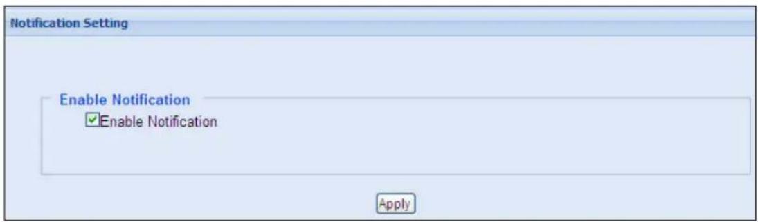
Figure 6-10
Note: When mobile notification is enabled on the camera's Web interface, the same function will automatically be enabled on myGVcloud Portal (Figure 3-6).
6.6.2 myGVcloud
You can enable or disable the myGVcloud account in this section.
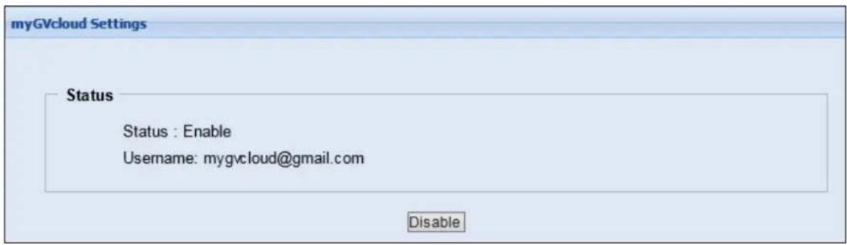
Figure 6-11
[Status] Select Disable to delete the camera from the myGVcloud account. If you want to add the camera back to your account, run the myGVcloud Setup Wizard to find the camera's IP address and log in your myGVcloud account.
6.7 Monitoring
6.7.1 Monitoring
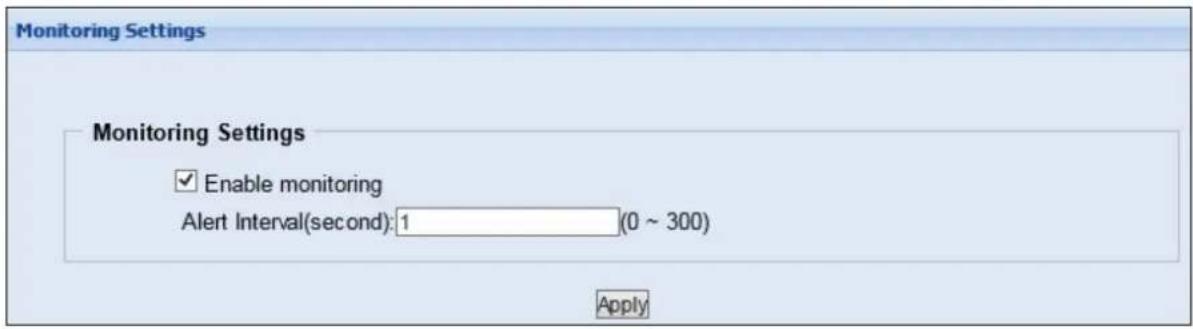
Figure 6-12
[Monitoring Settings] Manually activate motion detection monitoring. Select one of the following options and then click the Apply button.
■ Enable monitoring: Manually start recording upon motion detection.
■ Alert Interval (second): Set the time interval from 0 second to 300 seconds between each notification upon motion detection. If you set 10 seconds, when there is more than 1 motion event detected during the period, you will only receive 1 notification for the detected events.
6.7.2 Storage Settings
The GV-Cloud Camera supports memory cards for video and audio recordings. Make sure the memory card is using FAT32 format.
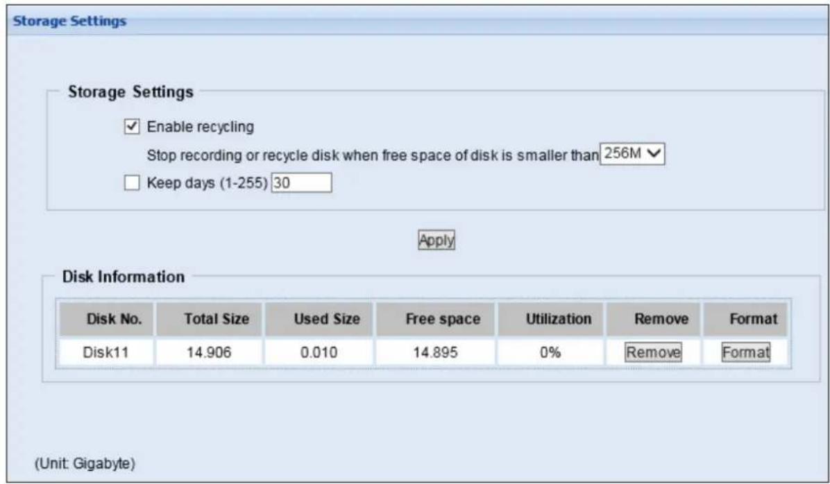
Figure 6-13
[Enable recycling] If this option is selected, when the space of the storage device is lower than the specified space, the system will overwrite the oldest recorded files. If this option is not selected, the system will stop recording when the specified space is reached.
[Keep days (1-255)] Specify the number of days to keep the files from 1 day to 255 days. When both Keep days and Enable recycling are selected, the system applies whichever condition comes first. For example, if the specified smallest amount of storage space comes earlier than the designated keep days, then recycle is applied first.
Click Apply to enable the above settings.
[Disk Information]
This section shows the details of the attached storage device.
To add a memory card:
- Insert the memory card to the camera.
- Click the Format button.
- After the format is complete, the partition information will display.
To remove a memory card:
- Click the Remove button.
- When you are prompted to ensure the action, click Yes. The page is refreshed and the partition information is cleaned.
- Remove the memory card from the camera.
Note:
- The camera supports a maximum storage capacity of 32 GB.
- If Enable Recycle is selected, the available space of the storage device must be higher than the space you specified at the Stop recording or recycle disk when free space of disk is smaller than x option. Otherwise no video will be recoded.
- The recording data may be lost if you remove the storage device during recording.
- If the storage device was not removed properly, the storage device may be damaged. In this case, re-plug the storage device back to the camera and reboot the camera. The system will repair the data automatically.
6.8 Network
The Network section includes some basic but important network configurations that enable the camera to be connected to a TCP/IP network.
6.8.1 Wireless
Set up the client mode before enabling the wireless function. This page is only available for GV-HCW Cameras.
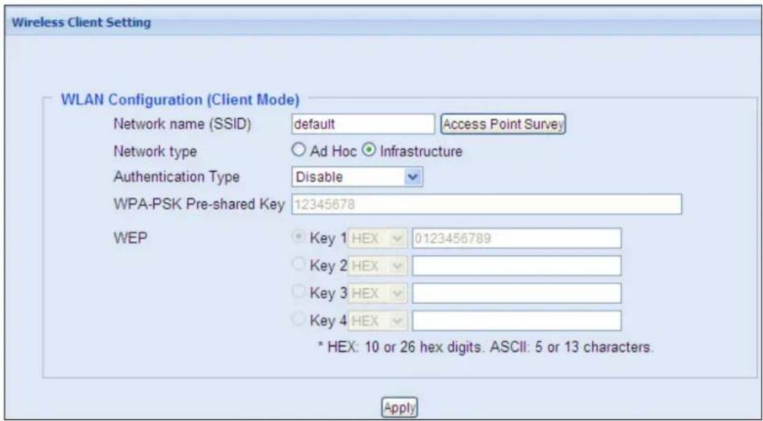
Figure 6-14
■ Network name (SSID): The SSID (Service Set Identify) is a unique name that identifies a particular wireless network. Type SSID of the Wireless LAN group or Access Point you are going to connect to.
■ Access Point Survey: Click this button to search all the available Access Points (Infrastructure mode) and wireless stations (AD-Hoc mode) within the LAN.
■ Network type: Select the network mode Ad Hoc or Infrastructure.
■ Infrastructure: Connect to the Internet via the Access Point. This mode further gives wireless access to the Internet or data sharing under a previously wired environment.
■ Ad-Hoc: A Peer-to-Peer mode. This mode connects to other computer with the WLAN card, and does not need the Access Point to connect to each other.
■ Authentication Type: Select one of these network authentication and data encryption: Disable, WEP, WPAPSK-TKIP, WPAPSK-AES, WPA2PSK-TKIP or WPA2PSK-AES.
■ Disabled: No authentication is needed within the wireless network.
■ WEP (Wired Equivalent Privacy): A type of data encryption. Type up to four WEP Keys in HEX or ASCII format. Note that if you use HEX format, only digits 0-9 and letters A-F, a-f are valid.
■ WPAPSK-TKIP and WPA2PSK-TKIP: Type WPA-PSK (Pre-Shared Key) for data encryption.
■ WPAPSK-AES and WPA2PSK-AES: Type WPA-PSK (Pre-Shared Key) for data encryption.
To set up the dynamic or static IP address for wireless connection, see 6.8.3 LAN.
Note:
- Your encryption settings must match those used by the Access Points or wireless stations with which you want to associate.
- When you lose the wireless access, you can still access the unit by connecting it to a LAN and search for the camera using myGVcloud CamWizard.
- When Ad Hoc is used, only WEP encryption is supported.
6.8.2 Status
This section displays the information of current network status.
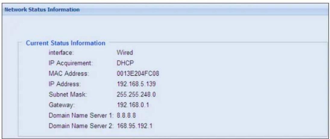
Figure 6-15
6.8.3 LAN
According to your network environment, select among Static IP, DHCP and PPPoE.
LANConfiguration
Network type
- Wired Ethernet Select this option to use wired 10/100Mbps ethernet
○ Wireless Select this option to use Wireless
LAN Configuration
Dynamic IP address Select this option to obtain IP address from a DHCP server Test DHCP
- Static IP address Select this option to enter a Static IP address manually
IP Address: 192.168.5.65
Subnet Mask: 255.255.248.0
Router/Gateway: 192.168.0.1
Primary DNS: 192.168.0.1
Secondary DNS: 192.168.0.2 (Optional)
○ PPPoE Select this option to establish a DSL connection
Username:
Password:
Wireless
Dynamic IP address Select this option to obtain IP address from a DHCP server Test DHCP
Static IP address Select this option to enter a Static IP address manually
IP Address: 192.168.100.10
Subnet Mask: 255 255 255 0
Router/Gateway: 192.168.0.1
Primary DNS: 192.168.0.1
Secondary DNS: 192.168.0.2 (Optional)
Apply
Figure 6-16
[Network type]
This function is only supported for GV-HCW Cameras. Select Wired Ethernet or Wireless according to the network environment. To enable the Wireless connection, see 6.8.1 Wireless to configure the wireless settings first, and then select either Dynamic or Static IP address in the Wireless Settings field.
[LAN Configuration]
■ Dynamic IP address: The network environment has a DHCP server which will automatically assign a dynamic IP address to the camera. Click the Test DHCP button to see the currently assigned IP address or look up the dynamic IP address using the Scan Camera function in the myGVcloud Setup Wizard.
■ Static IP address: Assign a fixed IP to the camera. Type the camera's IP address, Subnet Mask, Router/Gateway, Primary DNS server and Secondary DNS server.
■ PPPoE: The network environment is xDSL connection. Type the Username and Password provided by ISP to establish the connection. If you use the xDSL connection with dynamic IP addresses, first use the DDNS function to obtain a domain name linking to the camera's changing IP address.
For details on Dynamic DNS Server Settings, see 6.8.4 Advanced TCP/IP.
[Wireless] This function is only supported for GV-HCW Cameras.
■ Dynamic IP address: The network environment has a DHCP server which will automatically assign a dynamic IP address to the camera. Click the Test DHCP button to see the currently assigned IP address or look up the dynamic IP address using the Scan Camera function in the myGVcloud Setup Wizard.
■ Static IP address: Assign a fixed IP to the camera. Type the camera's TCP/IP and DNS parameters in the Wireless Settings section. Type the camera's IP address, Subnet Mask, Router/Gateway, Primary DNS server and Secondary DNS server. For the default IP address, refer to the table below:
| Wired Ethernet Wireless | ||
| IP address 192.168.0.10 192.168.100.10 | ||
| Subnet Mask 255.255.255.0 | 255.255.255.0 | |
| Router/Gateway | 192.168.0.1 | 192.168.0.1 |
| Primary DNS server 192.168.0.1 192.168.0.1 | ||
| Secondary DNS server 192.168.0.2 192.168.0.2 | ||
Note:
- The default IP address for logging in the Camera's Web interface is 192.168.0.10.
- When the camera is using Wired connection, the LAN LED will be constant green. When the camera is using Wireless connection, the LAN LED will be constant blue. Note that the LAN LED may not be visible in some camera models.
6.8.4 Advanced TCP/IP
This section provides the advanced TCP/IP settings, including HTTP port, HTTPS, Streaming Port, RTSP and UPnP.
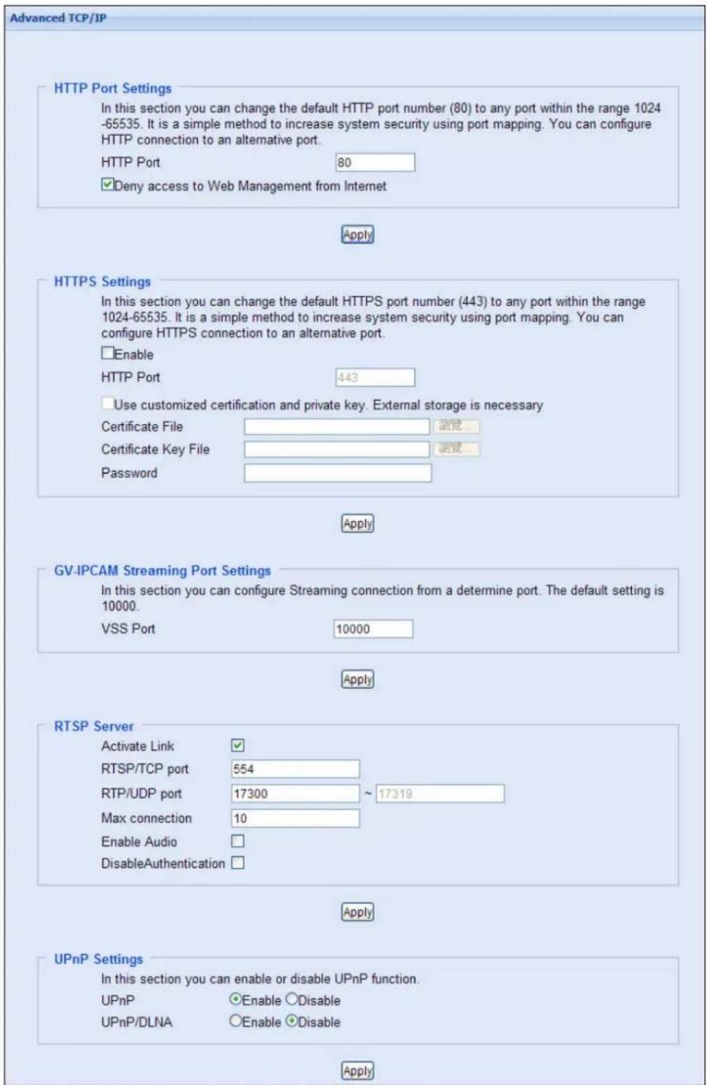
Figure 6-17
[HTTP Port Settings] The HTTP port enables connection of the camera to the Web. For security integration, the Administrator can hide the server from the general HTTP port by changing the default HTTP port of 80 to a different port number within the range of 1024 through 65535.
Deny access to Web Management from Internet: When enabled, you can only access the camera's Web interface in the same LAN.
[HTTPS Settings]
By enabling the HTTPS settings, you can access the camera through a secure protocol. The default HTTPS port is 443. You can use your own generated Certificate and Private Key or ones verified by the SSL authority. Click Browse to locate the Certificate file and
Certificate Key file, and type the password if the .pem files are protected by a password.
Click Apply. The Web interface will be restarted automatically and you will need to log in again.
Note: Only .pem file format is supported for Certification and Private Key.
[GV-IPCAM Streaming Port Settings] This function is currently not functional.
[RTSP Server]
■ Activate Links: Enable the RTSP service.
■ RTSP/TCP port: Keep the default value 554, or modify it if necessary.
■ RTP/UDP port: Keep the default range from 17300 to 17319, or modify it if necessary. The number of ports for use is limited to 20.
■ Max connection: Set the maximum number of connections to the camera. The default number of connections is 10.
■ Enable Audio: Enable the audio function for the camera. This function is not supported in GV-UBLC Cameras.
■ Disable Authentication: By default, when accessing live view through RTSP command, the ID and password of the camera are required. Select this option to disable the authentication prompt.
©
6.9 Management
The Management section includes the settings of data and time and user account. You can also view the firmware version and execute certain system operations.
6.9.1 Date and Time
The date and time settings are used for date and time stamps on the image.
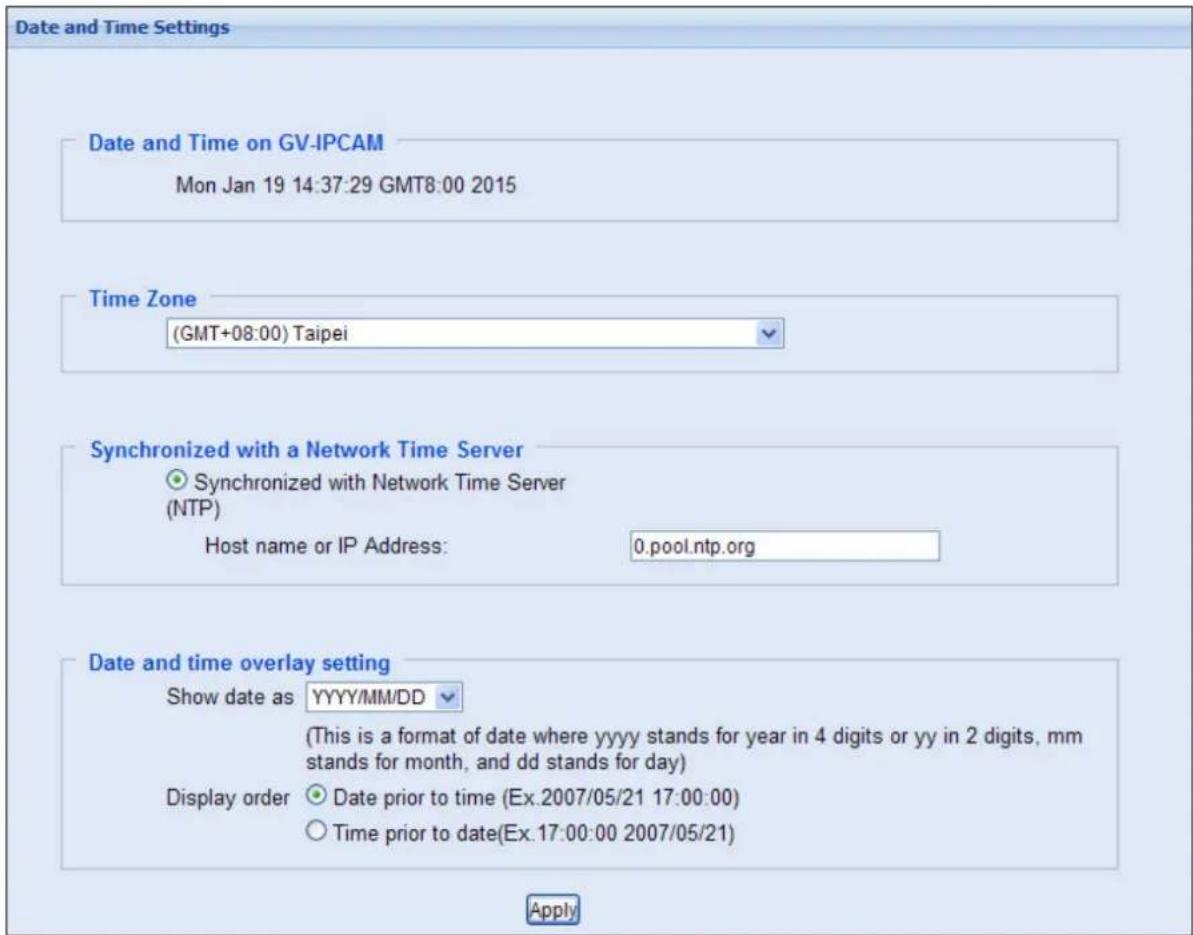
Figure 6-18
[Date & Time on GV-IPCAM] Displays the current date and time on the camera.
[Time Zone] Set the time zone for local settings.
[Synchronized with a Network Time Server] By default, the camera automatically updates its internal clock with the timeserver of 0.pool.ntp.org. You can change the host name or IP address to the timeserver of interest.
[Date and time overlay settings] Select the display format of date and time stamps on the image. For this function to work, you must enable the Overlaid with date stamps and Overlaid with time stamps options. For details on the text overlay settings, see 6.5.2 OSD.
6.9.2 User Account
Two types of users are allowed to log into the GV-Cloud Camera: Administrator and Guest. The Administrator has full access to all system configurations, while the Guest can only access the live view and network status.
You can change the login name and password of Administrator and Guest. The default Administrator login name and password are admin; the default Guest login name and password are guest.
By default, the login status is Administrator. To allow a Guest user to log in, in Advanced Setting field, select Enable Guest Account.
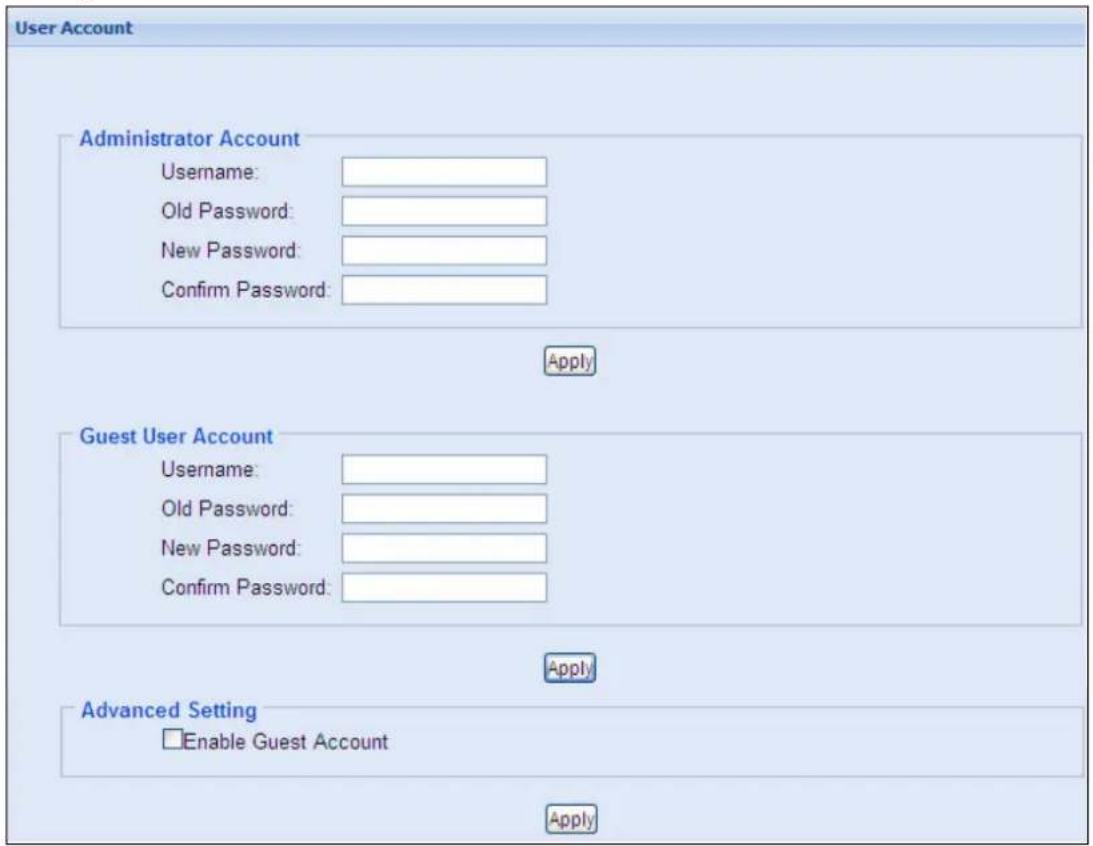
Figure 6-19
6.9.3 Tools
You can execute certain system operations and view the firmware version.
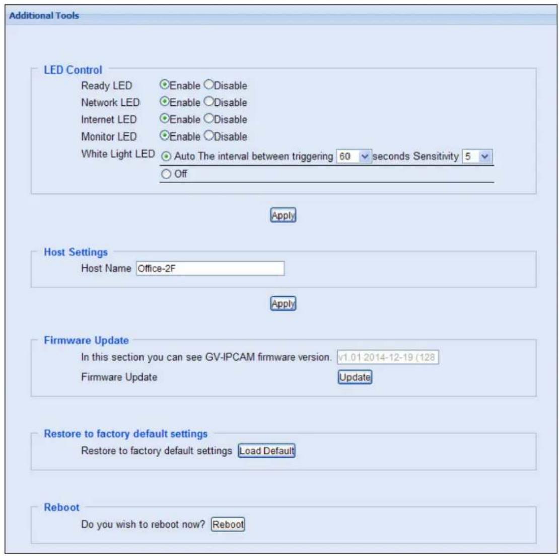
Figure 6-20
[LED Control] Choose whether to enable the LED light for the status of device, LAN, WAN, monitor and alarm. The options available vary depending on the camera model.
■ White Light LED: Select Auto for the LED to illuminate the scene automatically when the PIR sensor detects any motion within 5 meters. This function is only available for GV-HCW Cameras.
For The interval between triggering, select the duration for the White Light LED to light up at full intensity. If you set 30 seconds, when a motion lasts over 30 seconds, the LED will light up with less intensity. The default value is 60 seconds.
For the Sensitivity, select a level for low light detection. The higher the value, the easier the White Light LED is to be triggered. The default value is 5.
[Host Settings] Type a descriptive name for the camera.
[Firmware Update] You can see the firmware version of the camera in this field. To upgrade your camera, click update and choose the firmware file for upload.
[Restore to factory default settings] Click the Load Default button to restore factory default settings. After applying the default settings, it is required to configure the camera's network settings again.
[Internal Temperature] Shows the current chipset temperature inside the camera. This function is not available for GV-HCW Cameras.
[Reboot] Click the Reboot button if you wish to restart the operation of the camera.
6.9.4 Language
Use the Language drop-down list to select the language for the Web interface. By default, the language used for the operating system will be selected if the language is supported. Currently, English, Traditional Chinese, Russian and Japanese are supported.
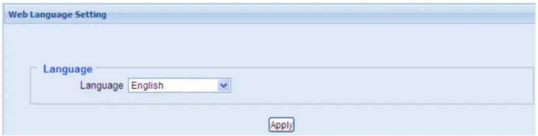
Figure 6-21
6.10 Upgrading System Firmware
GeoVision periodically releases updated firmware on the website. Simply download the new firmware into the camera using the Web interface.
Important Notes before You Start
Before you start upgrading the firmware, please read these important notes:
While the firmware is being updated,
- the power supply must not be interrupted, and
- do not unplug the Ethernet cable if the cable is the source of power supply (Power over Ethernet or PoE supported).
WARNING: The interruption of power supply during updating causes not only update failures but also damages to the camera. In this case, please contact your sales representative.
To upgrade the firmware, go to Tools under the Management section, click update under Firmware Update and choose the firmware file for upload.
Specifications
GV-HCW120
Camera
| Image Sensor | 1/2.5" progressive scan CMOS | |
| Picture Elements | 1280 (H) x 720 (V) | |
| Minimum Illumination | Color | 0.15 Lux |
| B/W | 0.10 Lux | |
| IR On | N/A | |
| Gain Control | Automatic | |
| S/N Ratio | 45 db | |
| WDR | Yes | |
| Dynamic Range | Up to 70 dB | |
| Shutter Speed | Automatic, Manual (1/5, 1/15, 1/30, 1/60) | |
| White Balance | Automatic, Manual (2800K ~ 8500K) | |
Optics Lens
| Megapixel | Yes |
| Day / Night Function | Yes (Electronic) |
| Lens Type | Fixed |
| Focal Length | 3.35 mm |
| Maximum Aperture | F/2.4 |
| Mount | M12 |
| Horizontal FOV | 67° |
| Image Format | 1/2.5” |
| Operation (Focus / Zoom / Iris) | Fixed |
Operation
| Video Compression | H.264 | |
| Video Streaming | Dual streams from H.264 | |
| Frame Rate | 30 fps at 1280 x 720 | |
| Image Setting | myGVcloud Portal | Sharpness, D/N Sensitivity, White Balance, Flicker-less, Image Orientation, Shutter Speed, Wide Dynamic Range (WDR), Defog, |
| Camera Web Interface | D/N Sensitivity, Backlight Compensation | |
| Audio Support | Two-Way Audio | |
| Audio Compression | AAC (16 kHz / 16 bit) | |
Network
| Interface | 10/100 Ethernet |
| Protocol | HTTP, HTTPS, TCP, UDP, DHCP, NTP, UPnP, RTSP |
| Wireless LAN | IEEE 802.11 b/g/n |
| Antenna Type | Built-in |
| Security | WEP, WPA-PSK(TKIP), WPA-PSK(AES), WPA2-PSK(TKIP), WPA2-PSK(AES) |
| Note: The signal range and data throughput may vary depending on the network conditions and environmental factors. | |
Mechanical
| Connectors | Power | DC Jack 5V |
| Ethernet | Ethernet (10 /100 Base-T), RJ45 | |
| Audio | Built-in microphone and speaker | |
| Local Storage | Micro SD card slot (SD / SDHC, version 2.0 only, Class 10) | |
| PIR Sensor | Built-in PIR sensor | |
| WPS Function | WPS button | |
| LED Indicators | 4 LEDs: Live View / Ready / Internet / Recording | |
| White Illumination LED | Yes | |
| Max. PIR / White Illumination LED Distance | 5 m (16.4 ft) | |
| Note: SDXC and USH1 card types are not supported. | ||
General
| Environment Temperature | 0°C ~ 50°C (32 °F ~ 122 °F) |
| Humidity | 10% to 90% (no condensation) |
| Power Source | 5V DC |
| Maximum Power Consumption | 6.67 W |
| Regulatory | CE, FCC, RCM, RoHS compliant |
| Dimension (L x W x H) | 65.8 x 99.8 x 39 mm (2.59 x 3.93 x 1.54 in)(Without mounting base and cover) |
| Weight | 100 g (0.22 lb) |
Applications
| Application Installation | myGVcloud CamWizard |
| Access from Web Browser using myGVcloud Portal | Camera live view, video recording, change video resolution, image snapshot, motion detection, tampering alarm, timeline payback from cloud storage, firmware upgrade, Picture -in-Picture, Picture-and-Picture, Cloud Service, YouTube live streaming |
| Live Viewing | myGVcloud Portal, myGVcloud CamViewer, myGVcloud CamApp |
| Storage Management | Cloud storage through myGVcloud Portal |
| Firmware Upgrade | Through myGVcloud Portal or camera Web interface |
| Mobile Phone Support | myGVcloud CamApp for iOS and Android devices |
| Language | English / Traditional Chinese / Russian / Japanese |
All specifications are subject to change without notice.
GV-UBXC1301
Camera
| Image Sensor | 1/2.5" progressive scan CMOS | |
| Picture Elements | 1280 (H) x 720 (V) | |
| Minimum Illumination | Color | 0.15 Lux |
| B/W | 0.10 Lux | |
| IR On | 0 Lux | |
| Gain Control | Automatic | |
| S/N Ratio | 50 db | |
| WDR | Yes | |
| Dynamic Range | Up to 70 dB | |
| Shutter Speed | Automatic, Manual (1/5, 1/15, 1/30, 1/60) | |
| White Balance | Automatic, Manual (2800K ~ 8500K) | |
Optics Lens
| Megapixel | Yes |
| Day / Night Function | Yes (Electronic) |
| Lens Type | Fixed |
| Focal Length | 2.8 mm |
| Maximum Aperture | F/2.0 |
| Mount | M12 |
| Horizontal FOV | 69° |
| Image Format | 1/3" |
| Operation (Focus / Zoom / Iris) | Fixed |
| IR LED Quantity | 4 IR LEDs |
| Max. IR Distance | 10 m (32.81 ft) |
Operation
| Video Compression | H.264 | |
| Video Streaming | Dual streams from H.264 | |
| Frame Rate | 30 fps at 1280 x 720 | |
| Image Setting | myGVcloud Portal | Sharpness, D/N Sensitivity, White Balance, Flicker-less, Image Orientation, Shutter Speed, Wide Dynamic Range (WDR), Defog |
| Camera Web Interface | D/N Sensitivity, Backlight Compensation | |
| Audio Support | Two-Way Audio | |
| Audio Compression | AAC (16 kHz / 16 bit) | |
Network
| Interface | 10/100 Ethernet |
| Protocol | HTTP, HTTPS, TCP, UDP, DHCP, NTP, UPnP, RTSP |
| Note: The signal range and data throughput may vary depending on the network conditions and environmental factors. | |
Mechanical
| Temperature Detector | Yes | |
| Connectors | Power | 2-pin terminal block, PoE |
| Ethernet | Ethernet (10 /100 Base-T), RJ45 | |
| Audio | 1 In (Built-in Microphone)1 Out (Stereo phone jack, 3.5 mm / 0.14") | |
| Local Storage | Micro SD card slot (SD / SDHC, version 2.0 only, Class 10) | |
| LED Indicators | 2 LEDs: Power / Status | |
| Note: SXHC and USH1 card types are not supported. | ||
General
| Environment Temperature | 0°C ~ 40°C (32 °F ~ 104 °F) |
| Humidity | 10% to 90% (no condensation) |
| Power Source | 5V DC / PoE (IEEE 802.3af) |
| Maximum Power Consumption | 6.5 W |
| Regulatory | CE, FCC, RCM, RoHS compliant |
| Dimension (L x W x H) | 95 x 45 x 40 mm (3.7 x 1.8 x 1.6 “) |
| Weight | 120 g (0.26 lb) |
Power over Ethernet
| PoE Standard | IEEE 802.3af Power over Ethernet / PD |
| PoE Power Supply Type | End-Span |
| PoE Power Output | Per Port 48V DC, 350mA. Max. 15.4 watts |
Applications
| Installation | myGVcloud CamWizard |
| Access from Web Browser using myGVcloud Portal | Camera live view, video recording, change video resolution, image snapshot, motion detection, tampering alarm, timeline payback from cloud storage, firmware upgrade, Picture -in-Picture, Picture-and-Picture, Cloud Service, YouTube live streaming |
| Live Viewing | myGVcloud Portal, myGVcloud CamViewer, myGVcloud CamApp |
| Storage Management | Cloud storage through myGVcloud Portal |
| Firmware Upgrade | Through myGVcloud Portal or camera Web interface |
| Mobile Phone Support | myGVcloud CamApp for iOS and Android devices |
| Language | English / Traditional Chinese / Russian / Japanese |
All specifications are subject to change without notice.
GV-UBLC1301
Camera
| Image Sensor | 1/2.5" progressive scan CMOS | |
| Picture Elements | 1280 (H) x 720 (V) | |
| Minimum Illumination | Color | 0.15 Lux |
| B/W | 0.10 Lux | |
| IR On | 0 Lux | |
| Gain Control | Automatic | |
| S/N Ratio | 45 db | |
| WDR | Yes | |
| Dynamic Range | Up to 70 dB | |
| Shutter Speed | Automatic, Manual (1/5, 1/15, 1/30, 1/60) | |
| White Balance | Automatic, Manual (2800K ~ 8500K) | |
Optics Lens
| Megapixel | Yes |
| Day / Night Function | Yes (Electronic) |
| Lens Type | Fixed |
| Focal Length | 2.8 mm |
| Maximum Aperture | F/2.0 |
| Mount | M12 |
| Horizontal FOV | 69° |
| Image Format | 1/3” |
| Operation (Focus / Zoom / Iris) | Fixed |
| IR LED Quantity | 4 IR LEDs |
| Max. IR Distance | 10 m (32.81 ft) |
Operation
| Video Compression | H.264 | |
| Video Streaming | Dual streams from H.264 | |
| Frame Rate | 30 fps at 1280 x 720 | |
| Image Setting | myGVcloud Portal | Sharpness, D/N Sensitivity, White Balance, Flicker-less, Image Orientation, Shutter Speed, Wide Dynamic Range (WDR), Defog, |
| Camera Web Interface | D/N Sensitivity, Backlight Compensation | |
| Audio Support | N/A | |
Network
| Interface | 10/100 Ethernet |
| Protocol | HTTP, HTTPS, TCP, UDP, DHCP, NTP, UPnP, RTSP |
| Note: The signal range and data throughput may vary depending on the network conditions and environmental factors. | |
Mechanical
| Temperature Detector | Yes | |
| Connectors | Power | 2-pin terminal block, PoE |
| Ethernet | Ethernet (10 /100 Base-T), RJ45 | |
| Audio | N/A | |
| Local Storage | Micro SD card slot (SD / SDHC, version 2.0 only, Class 10) | |
| Note: SXHC and USH1 card types are not supported. | ||
General
| Environment Temperature | -30°C ~ 45°C (-22 °F ~ 113 °F) |
| Humidity | 10% to 90% (no condensation) |
| Power Source | 5V DC / PoE (IEEE 802.3af) |
| Maximum Power Consumption | 5.52 W |
| Regulatory | CE, FCC, RCM, RoHS compliant |
| Ingress Protection | IP67 |
| Vandal Resistance | IK10 for metal casing |
| Dimension (L x W x H) | 124 x 65 x 69 mm (4.8 x 2.6 x 2.7 in) |
| Weight | 730 g (1.6 lb) |
Power over Ethernet
| PoE Standard | IEEE 802.3af Power over Ethernet / PD |
| PoE Power Supply Type | End-Span |
| PoE Power Output | Per Port 48V DC, 350mA. Max. 15.4 watts |
Applications
| Installation | myGVcloud CamWizard |
| Access from Web Browser using myGVcloud Portal | Camera live view, video recording, change video resolution, image snapshot, motion detection, tampering alarm, timeline payback from cloud storage, firmware upgrade, Picture -in-Picture, Picture-and-Picture, Cloud Service, YouTube live streaming |
| Live Viewing | myGVcloud Portal, myGVcloud CamViewer, myGVcloud CamApp |
| Storage Management | Cloud storage through myGVcloud Portal |
| Firmware Upgrade | Through myGVcloud Portal or camera Web interface |
| Mobile Phone Support | myGVcloud CamApp for iOS and Android devices |
| Language | English / Traditional Chinese / Russian / Japanese |
All specifications are subject to change without notice.
GV-MFDC1501
Camera
| Image Sensor | 1/3" progressive scan super low lux CMOS | |
| Picture Elements | 1280 (H) x 720 (V) | |
| Minimum Illumination | Color | 0.01 Lux |
| B/W | ||
| Gain Control | Automatic | |
| S/N Ratio | 55 db | |
| WDR | Yes | |
| Dynamic Range | Up to 70 dB | |
| Shutter Speed | Automatic, Manual (1/5, 1/15, 1/30, 1/60) | |
| White Balance | Automatic, Manual (2800K ~ 8500K) | |
Optics Lens
| Megapixel | Yes |
| Day / Night Function | Yes (Electronic) |
| Lens Type | Fixed |
| Focal Length | 2.8 mm |
| Maximum Aperture | F/2.0 |
| Mount | M12 |
| Horizontal FOV | 87° |
| Image Format | 1/3” |
| Operation (Focus / Zoom / Iris) | Fixed |
Operation
| Video Compression | H.264 | |
| Video Streaming | Dual streams from H.264 | |
| Frame Rate | 30 fps at 1280 x 720 | |
| Image Setting | myGVcloud Portal | Sharpness, D/N Sensitivity, White Balance, Flicker-less, Image Orientation, Shutter Speed, Wide Dynamic Range (WDR), Defog, Super Low Lux |
| Camera Web Interface | D/N Sensitivity, Backlight Compensation | |
| Audio Support | Two-Way Audio | |
| Audio Compression | AAC (16 kHz / 16 bit) | |
Network
| Interface | 10/100 Ethernet |
| Protocol | HTTP, HTTPS, TCP, UDP, DHCP, NTP, UPnP, RTSP |
| Note: The signal range and data throughput may vary depending on the network conditions and environmental factors. | |
Mechanical
| Temperature Detector | Yes | |
| Camera Angle Adjustment | Pan | -45° ~ 45° |
| Tilt | 0° ~ 90° | |
| Connectors | Power | 2-pin terminal block, PoE |
| Ethernet | Ethernet (10 /100 Base-T), RJ45 | |
| Audio | 1 In (Built-in Microphone)1 Out (RCA female for speaker) | |
| Local Storage | Micro SD card slot (SD / SDHC, version 2.0 only, Class 10) | |
| LED Indicators | 4 LEDs: Link, ACT, Power, Status | |
| Note: SXHC and USH1 card types are not supported. | ||
General
| Environment Temperature | 0°C ~ 50°C (32 °F ~ 122 °F) |
| Humidity | 10% to 90% (no condensation) |
| Power Source | 5V DC / PoE (IEEE 802.3af) |
| Maximum Power Consumption | 6 W |
| Regulatory | CE, FCC, RCM, RoHS compliant |
| Dimension (L x W x H) | ∅ 106 x 53.9 mm (4.2 x 2.1") |
| Weight | 280 g (0.62 lb) |
Power over Ethernet
| PoE Standard | IEEE 802.3af Power over Ethernet / PD |
| PoE Power Supply Type | End-Span |
| PoE Power Output | Per Port 48V DC, 350mA. Max. 15.4 watts |
Applications
| Installation | myGVcloud CamWizard |
| Live Viewing | myGVcloud Portal, myGVcloud CamViewer, myGVcloud CamApp |
| Access from Web Browser using myGVcloud Portal | Camera live view, video recording, change video resolution, image snapshot, motion detection, tampering alarm, timeline payback from cloud storage, firmware upgrade, Picture -in-Picture, Picture-and-Picture, Cloud Service, YouTube live streaming |
| Storage Management | Cloud storage through myGVcloud Portal |
| Firmware Upgrade | Through myGVcloud Portal or camera Web interface |
| Mobile Phone Support | myGVcloud CamApp for iOS and Android devices |
| Language | English / Traditional Chinese / Russian / Japanese |
All specifications are subject to change without notice.
Appendix
A. Settings for Internet Explorer 8 or Later
If you use Internet Explorer 8 or later, it is required to complete the following setting.
- Set the Security to Medium-high (default).
- Enable Allow previously unused ActiveX controls to run without prompt.
- Disable Only allow approved domains to use ActiveX without prompt.
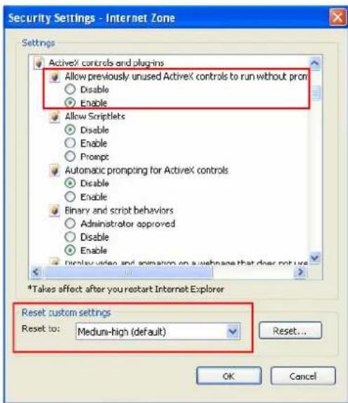
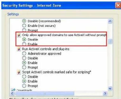
B. Changing the Default Media Player for Event Playback
The motion events in myGVcloud Portal are recorded in .mp4 format, and thus can be played back using any media player that supports .mp4 format. The following media players have been tested for compatibility with myGVcloud Portal:
- Quick Time V7.7.2 or later
• VLC Media Player V2.1.0 or later
• Windows Media Player V11.0 or later - KMPlayer V3.7 or later
To change the default media player for playback:
- Go to Window's Control Panel, go to Programs and select Make a file type always open in a specific program.
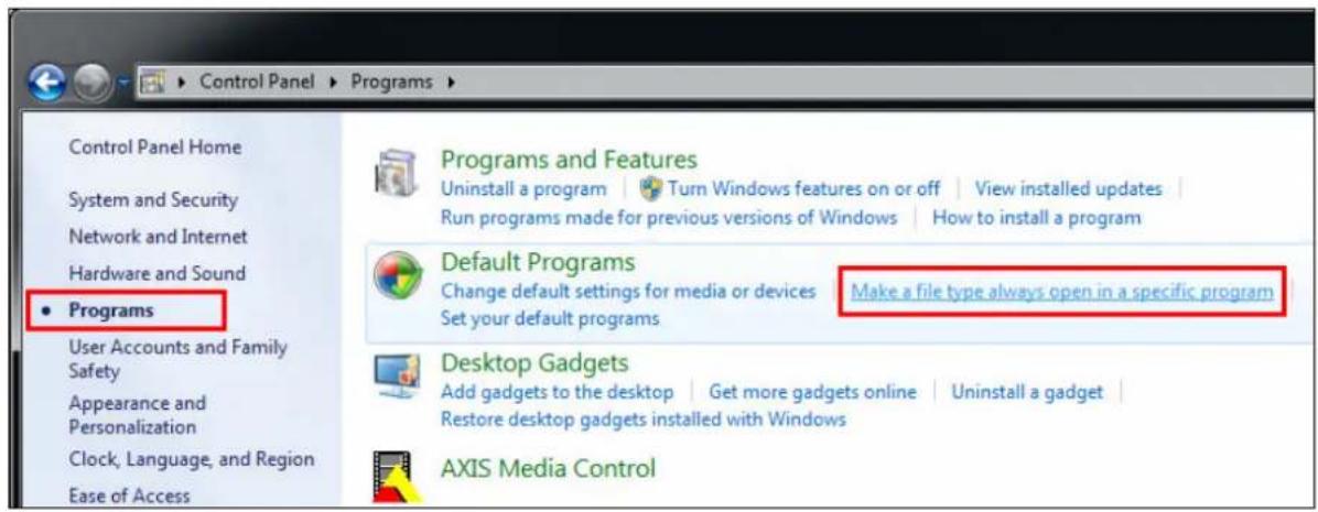
- Find the .mp4 file type and click the Change Program button.
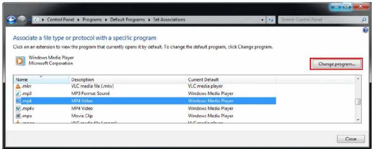
- Choose the program you want to use to open .mp4 files and click OK.
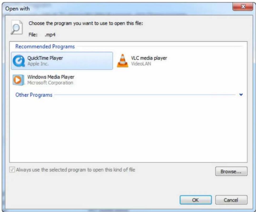
C. Setting Live Streaming on YouTube or UStream
To live stream camera live view, you need to have an account for YouTube, or UStream, and complete the required settings to obtain the stream name / key and RTMP server URL. Copy and paste the obtained stream name / key and RTMP server URL to myGVcloud Portal (Cloud Service tab > Live streaming sharing).
YouTube:
- Log in your YouTube account, select My Channel, and click Video Manager.
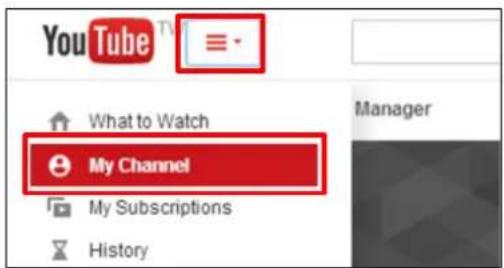
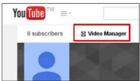
- Select Live Events under Video Manager and click the Enable live streaming button.
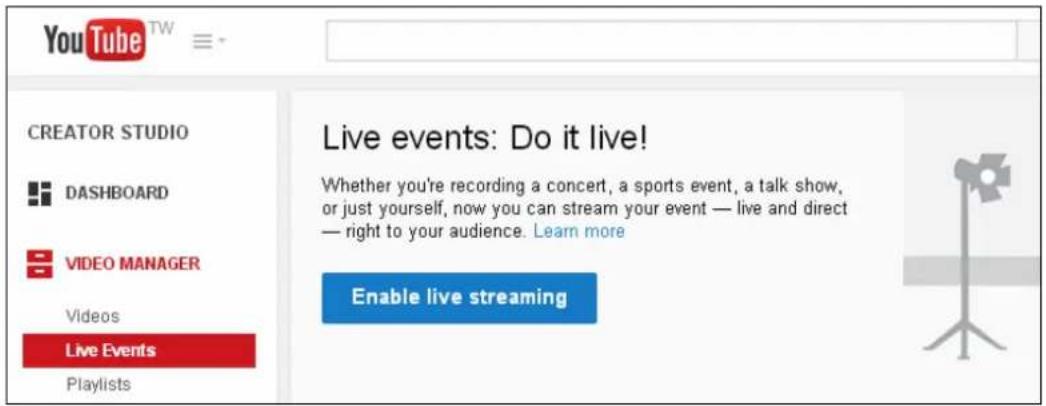
- Name the live stream, set the Type to Custom and click the Create Event button. Make sure the video is set to Public or Unlisted.
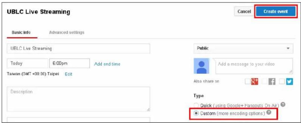
- Under Basic ingestion, select a resolution that is equal to or smaller than the camera's resolution.
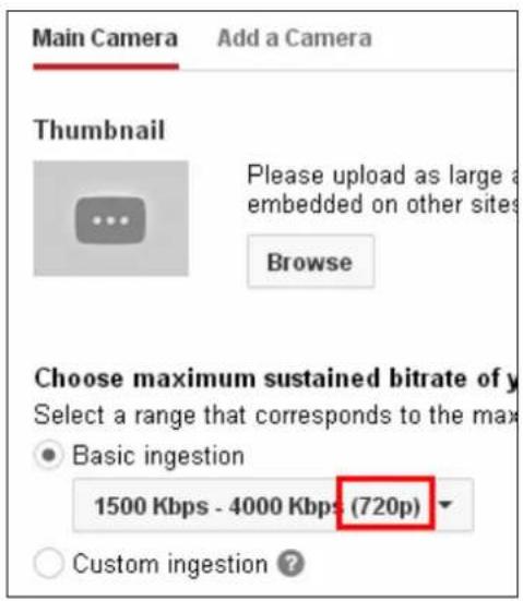
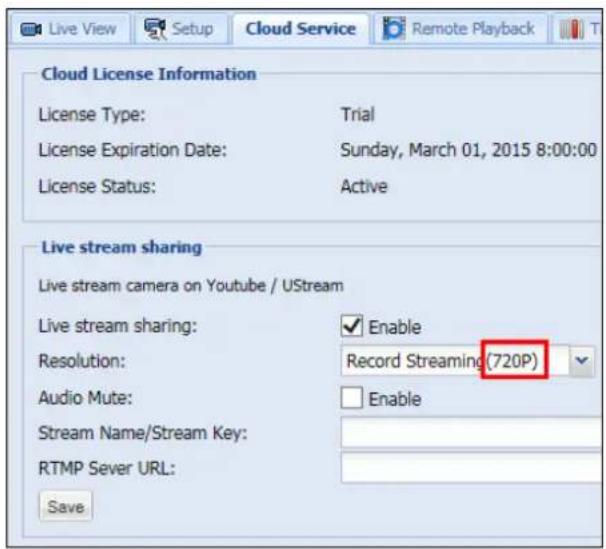
- Select Other encoders and copy and paste Stream name and Primary Server URL to myGVcloud Portal.

- Click Live Control Room to preview and start streaming.
You can also watch the demo video below to see how to set up live stream.
https://www.youtube.com/watch?v=gMGNp5735_Y
UStream
Refer to the instructions below on how to set up live stream:
https://ustream.zendesk.com/entries/21649743-How-to-stream-to-Ustream-using-Wirecast-
FMLE-TriCaster-or-any-RTMP-encoder
- GeoVision Inc
- © 2015 GeoVision, Inc. All rights reserved.
- Contents
- Important Notes ......v
- Chapter 1 Introduction....1
- Chapter 2 Getting Started....24
- Chapter 3 myGVcloud Portal....31
- Chapter 4 myGVcloud CamViewer....49
- Chapter 5 myGVcloud CamApp .... 54
- Chapter 6 Camera Web Interface 62
- Management 87
- Upgrading System Firmware 92
- Specifications....93
- GV-HCW120....93
- GV-UBXC1301....96
- GV-UBLC1301....99
- GV-MFDC1501 102
- Appendix 105
- Important Notes
- Note for Cloud License
- Note for Memory Card
- Chapter 1 Introduction
- Ideal Solution for Small Businesses
- Remote Access from PC and Mobile Devices
- Key Features
- myGVcloud Portal, CamViewer and CamApp
- GV-Cloud Cameras
- GV-HCW120
- GV-UBXC1301
- GV-UBLC1301
- GV-MFDC1501
- Packing List
- GV-HCW120
- GV-UBXC1301
- GV-UBLC1301
- GV-MFDC1501
- Camera Overview
- GV-HCW120
- GV-UBXC1301
- GV-UBLC1301
- GV-MFDC1501
- Installing the Camera
- GV-HCW120 and GV-UBXC1301
- GV-UBLC1301
- IMPORTANT:
- GV-MFDC1501
- Connecting the Camera
- GV-HCW120
- Note:
- GV-UBXC1301 and GV-MFDC1501
- GV-UBLC1301
- Waterproofing and Connecting the Network Cable
- Connecting to Power
- Chapter 2 Getting Started
- Setting Up the Camera
- Registering myGVcloud Account
- Link camera to myGVcloud
- Create a myGVcloud account
- Installing myGVcloud CamViewer or Mobile
- Applications
- Chapter 3 myGVcloud Portal
- The Main Screen
- The Live View Window
- Camera Settings
- [Basic]
- [Video / Audio]
- [Event Monitor]
- [Tampering Alarm]
- [Mobile Notification]
- [Storage]
- [Advanced Image Setting]
- Cloud Service
- Remote Playback
- Timeline (Cloud)
- General Account Settings
- [User Account]
- [General Setup]
- Chapter 4 myGVcloud CamViewer
- Accessing Live View and Recorded Videos
- General Setting
- Chapter 5 myGVcloud CamApp
- Supported Operating Systems:
- Logging In myGVcloud Account
- Configuring the Camera Settings
- Accessing Camera Live View
- Playing Back Recordings
- Notification
- Configure myGVcloud CamApp Settings
- [Login Account]
- [Live View]
- [System Setting]
- Chapter 6 Camera Web Interface
- Logging in the Camera's Web Interface
- List of Menu Option
- Event List
- Live View
- The Live View Window
- Internet Explorer
- Non-IE Browsers
- Snapshot of Live Video
- Video Recording
- Picture-in-Picture and Picture-and-Picture View
- Picture-in-Picture View
- Picture-and-Picture View
- Video Settings
- Streaming 1 / 2
- [Special View Setting – Additional functions for Live View]
- OSD
- Events and Alerts
- Notification
- myGVcloud
- Monitoring
- Monitoring
- Storage Settings
- [Disk Information]
- To add a memory card:
- To remove a memory card:
- Network
- Wireless
- Status
- LAN
- LANConfiguration
- Network type
- LAN Configuration
- Wireless
- [Network type]
- [LAN Configuration]
- Advanced TCP/IP
- [HTTPS Settings]
- [RTSP Server]
- Management
- Date and Time
- User Account
- Tools
- Language
- Upgrading System Firmware
- Important Notes before You Start
- Specifications
- Appendix
- Settings for Internet Explorer 8 or Later
- Changing the Default Media Player for Event Playback
- Setting Live Streaming on YouTube or UStream
- YouTube:
- UStream
Brand : Geovision
Model : GV-MFDC1501-0FV
Category : Security Camera