LP-2596K - Access Point Premiertek - Free user manual and instructions
Find the device manual for free LP-2596K Premiertek in PDF.

User questions about LP-2596K Premiertek
0 question about this device. Answer the ones you know or ask your own.
Ask a new question about this device
Download the instructions for your Access Point in PDF format for free! Find your manual LP-2596K - Premiertek and take your electronic device back in hand. On this page are published all the documents necessary for the use of your device. LP-2596K by Premiertek.
USER MANUAL LP-2596K Premiertek
Outdoor Long Range 802.11a/n 5GHz Wireless AP/CPE/Bridge (2T2R)
User Manual
Model: LP-2596K
Version: 1.0
Table of Contents
Notice....3
Chapter 1 Product Introduction....4
Product Outline 4
Product Feature....5
Application 5
Wireless ISP (WISP) Mode: 5
Bridge Mode: 6
Product Specification 7
General....7
IEEE 802.11 a/n Specification....7
Outline Introduction......8
Front view....8
Back view 8
LED Indication 9
I/O Interface....9
Product Label....10
Mounting Options 11
Pole Mount....11
Wall Mount 11
Package Content 12
Chapter 2 Hardware Installation....13
Connection Diagram 13
Installation Steps....13
Example - Scenario for IP surveillance 15
Chapter 3 Software Configuration....16
System Requirements:....16
Network Connection Setup: 16
Get started with LP-2596K....17
Web configuration of LP-2596K 18
Network 18
Radio....21
Information 26
Maintenance....28
System 29
Compliance....32
Notice
- This document is issued to guide users how to install and operate LP-2596K Outdoor Long Range 802.11a/n Wireless AP/CPE/Bridge. Please read the document carefully to avoid any damage which is caused by inappropriate use excluding from the warranty.
- Loopcomm Technology Inc. reserves the right to revise/update the content of LP-2596K user manual without advance notice.
Chapter 1 Product Introduction
Loopcomm LP-2596K is an Outdoor Long Range 5GHz Wireless AP/CPE/Bridge that provides wide coverage of network connection in existing environment. It can operate up to 300Mbps data rate by supporting IEEE 802.11a/n standard and with full WEP, WPA/WPA2 data security, Wireless LAN Access Control List and TKIP/AES encryption, It keeps the data transmission safe in any network connection mode. Moreover, it supports different operation modes for any user's applications like point to point network and IP surveillance.
Product Outline

natural_image
White rectangular electronic device labeled 'Loopcomm' with no visible text or symbols on its bodyProduct Feature
• Wireless Standards : IEEE 802.11a/n
• Data transmission rate up to 300 Mbps at 40 MHz bandwidth
• Operation Mode: Bridge/Wireless ISP
• Wireless Mode: AP/Station/WDS AP/WDS Station
- Reliable data security including WEP, WPA/WPA2, WPA-PSK/RADIUS, and WPA2-PSK/RADIUS with TKIP/AES encryption.
• DFS (Dynamic Frequency Selection) Channel supported (for EU version)
• Support SNMP V2 management, SSH, NTP, and Telnet.
• Support QoS bandwidth control
• MAC Access Control
• Built-in Web-based management and firmware upgrade
- PoE pass through available on Secondary Ethernet port (Configurable via Web UI)
• Remotely enable system reset by PoE Injector
Application
Wireless ISP (WISP) Mode:
LP-2596K can operate as station (client) in WISP mode to remotely receive broadband signal from WISP outdoor AP (base station) of Internet Service Provider (ISP).

flowchart
graph TD
    A["Internet"] --> B["WISP Outdoor AP"]
    B --> C["LP-2596K (Station)"]
Bridge Mode:
Since the antenna characteristics for LP-2596K is directional with high gain design, it can transmit RF signal for several miles. Based on this point, LP-2596K is greatly used to bridge at long distance transmission for point to point applications like IP surveillance, networking company.

flowchart
graph LR
    A["Internet"] --> B["ADSL2+ MODEM Router (LP-8696PW)"]
    B --> C["LP-2596K (AP)"]
    C --> D["LP-2596K (Station)"]
    D --> E["LAN"]
flowchart
graph LR
    A["NVR"] --> B["WDS AP"]
    B --> C["WDS Station"]
    C --> D["Switch (LP-5308C)"]
    D --> E["IP CAM (LPC-2001ID-F)"]
    B --> F["LP-2596K"]
    C --> G["LP-2596K"]
    style B fill:#f9f,stroke:#333
    style C fill:#f9f,stroke:#333
    style D fill:#ccf,stroke:#333
    style E fill:#cfc,stroke:#333
Product Specification
General
| Item Description | |
| SOC Atheros AR9344 | |
| Physical Interface One 10/100Mbps Fast Ethernet port (Main)One 10/100Mbps Fast Ethernet port (Secondary)Reset buttonEarth Ground | |
| LED Indicator Power, Secondary, Main, Signal Strength | |
| Antenna 14dBi PCB directional antenna | |
| Power Requirement 24V/1A Passive PoE (DC+: pin 4, 5; DC-: pin 7,8) | |
| Power Consumption 12W (maximum) | |
| Operating Temperature -20° ~ 70°C | |
| Storage Temperature | -30° ~ 80°C |
| Humidity | 0 ~ 90% |
| ESD Protection | Contact 4KV, Air 8KV |
| Lightning Protection | 1KV |
| Certification | FCC, CE |
IEEE 802.11a/n Specification
| Item | Description |
| Wireless Standard | IEEE 802.11a/n |
| Frequency | 5.18 ~ 5.825GHz |
| Channel | CH 36 ~ 165 (5.18 ~ 5.825GHz) for US versionCH 100 ~ 140 (5.5 ~ 5.68GHz) for EU version |
| Date Rate | 802.11a: 54Mbps802.11n (BW 20MHz): 144Mbps802.11n (BW 40MHz): 300Mbps |
| Modulation | 802.11a: BPSK, QPSK, 16QAM, 64QAM802.11n: OFDM |
| Media Access Control | CSMA/CA with ACK |
| Transmit Power | 802.11a: 25 +/-1 dBm802.11n: 24 +/-1 dBm |
| Receive Sensitivity | -94dBm@802.11a-93dBm@802.11n |
Outline Introduction
Front view

text_image
High Power 600mW 5GHz Amplifiers 14dBi Directional PCB Antenna Waterproof Sliding coverBack view

text_image
Serial Number label LED Indicator Secondary Main Wall mount holes Pole mount Product labelLED Indication

text_image
Power Secondary Main| LED Indicator Status Description | ||
| ON The LP-2596K | is powered ON. | |
| OFF The LP-2596K | is powered OFF. | |
| Secondary ON Port linked. | ||
| OFF No connection. | ||
| Blink Data is being transmitted or received on the Secondary Ethernet port. | ||
| Main ON Port linked. | ||
| OFF No connection. | ||
| Blink Data is being transmitted or received on the Main Ethernet port. | ||
| Signal Strength AP/Station mode It stands for the TX power strength as AP mode or connection quality as Station mode. | ||
I/O Interface
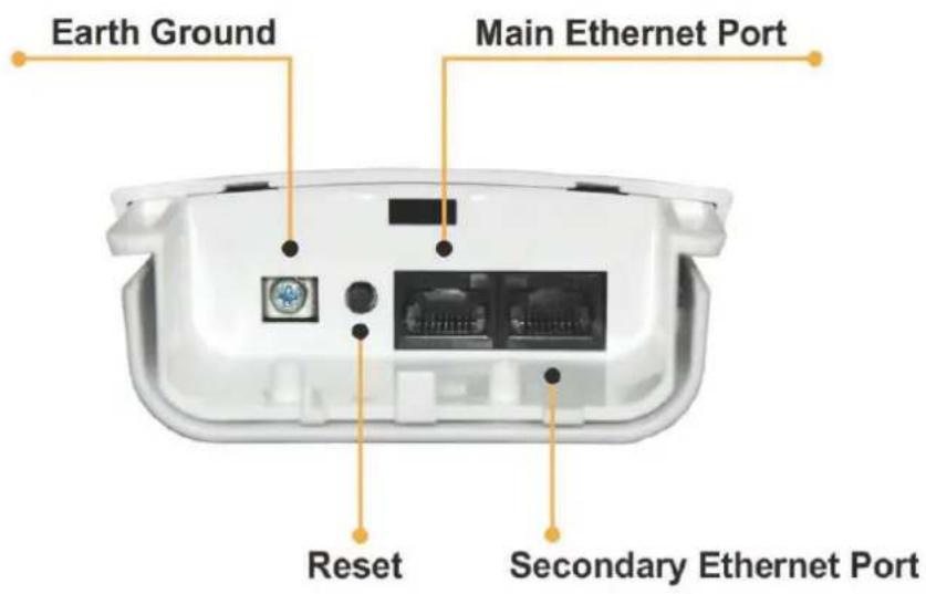
text_image
Earth Ground Main Ethernet Port Reset Secondary Ethernet Port| Item Description | |
| Main | It mainly used as Power over Ethernet (PoE) port, which allows the router powered up by PoE adapter when the connection is established by RJ-45 Cat.5 cable. It supports auto-sensing on 10/100M speed, half/ full duplex, and complies with IEEE 802.3/802.3u respectively. |
| Secondary | The Secondary Ethernet port allows users to connect to another device through RJ-45 Cat.5 cable. It supports auto-sensing on 10/100M speed, half/ full duplex, and complies with IEEE 802.3/802.3u respectively. |
| Reset Bottom | Press continually the reset button at least 5 seconds to reset the configuration parameters to factory defaults |
| Earth Ground | It used to connect the metal line to ground in order to avoid the device from external electrical damage. |
Note. LP-2596K built in PoE pass through function on Secondary Ethernet port. It means the Secondary Ethernet port is able to provide 24V power for a secondary device if this function enabled on Web Configuration (Please refer to the statement on Advanced Setting of Radio menu).
Product Label
It includes related essential information about LP-2596K stickered on the back of device.

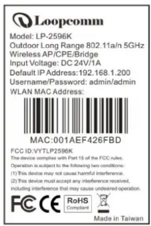
text_image
Loopcomm Model: LP-2596K Outdoor Long Range 802.11a/n 5GHz Wireless AP/CPE/Bridge Input Voltage: DC 24V/1A Default IP Address: 192.168.1.200 Username/Password: admin/admin WLAN MAC Address: MAC:001AEF426FBD FCC ID: VYTLP2596K The device complies with Part 15 of the FCC rules. Operation is subject to the following two conditions: (1) This device may not cause harmful interference. (2) This device must accept any interference received, including interference that may cause undesired operation. FCC CE RoHS Compliant Made in Taiwan
text_image
59mmMounting Options
Pole Mount
Use cable tie and make it pass through the one of middle holes to fix and tie on the pole.
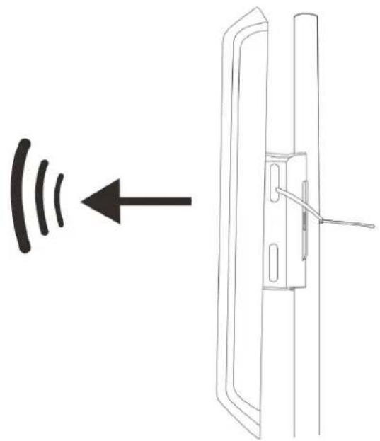
natural_image
Diagram showing a door with a switch and sound waves, no text or symbols presentWall Mount
Please fix the screws into the wall and hang LP-2596K on the corresponding screws.
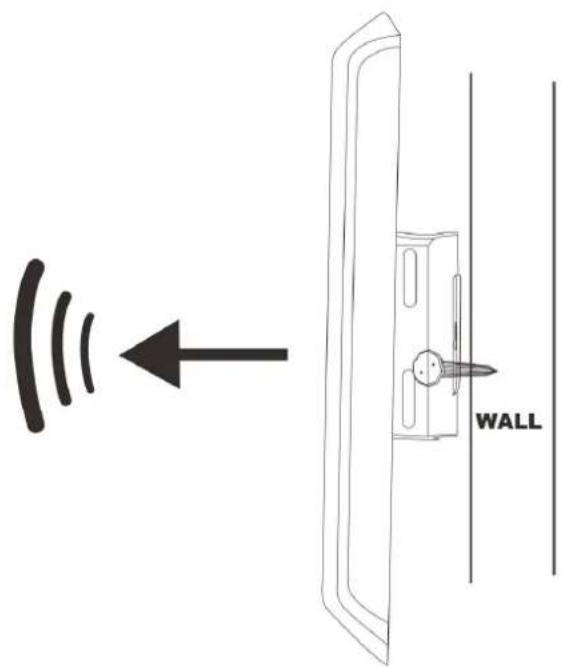
text_image
WALLPackage Content
The package content includes the following items, shown from left to right as figure.
- LP-2596K
• DC 24V/1A Power adapter - PoE Injector
- Product CD
- Cable Tie
- Quick Installation Guide (QIG)

Chapter 2 Hardware Installation
Connection Diagram
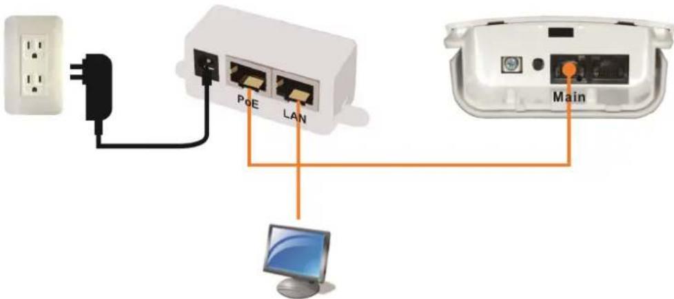
text_image
PoE LAN MainInstallation Steps
- Take off the water-proof sliding cover.
- Connect the Main Ethernet port of LP-2596K with a RJ-45 cable.

text_image
Reset Secondary Residual Setting | Impulse Print Mode #100% DIP/Service - Enable #200% User Status and Secondary / Intraholders #300% does only bonded Full InjectorNote. LP-2596K built in PoE pass through function on Secondary Ethernet port. It means the Secondary Ethernet port is able to provide 24V power for a secondary device if this function enabled on Web Configuration (Please refer to the statement on Advanced Setting of Radio menu).
- Make the water-proof sliding cover well installed.
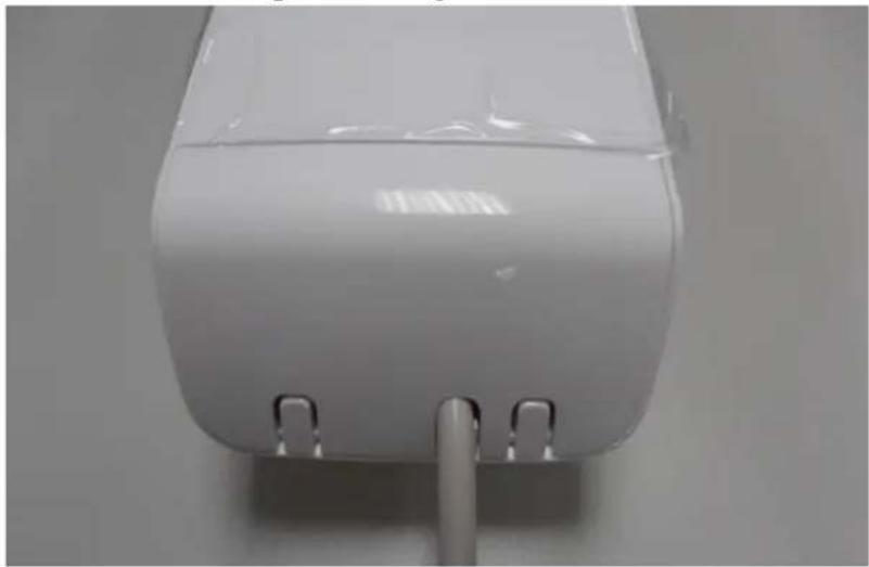
natural_image
Close-up of a white plastic appliance with two metallic clips at the bottom (no visible text or symbols)-
Connect PoE Injector to LP-2596K shown on diagram.
-
DC: Plug in the DC jack of 24V/1A power adapter
- PoE port: Connect to Main Ethernet port with a RJ-45 cable.
• LAN port: Connect to your computer/laptop for Web configuration. - Reset button: It allows user to remotely reset the system of LP-2596K.
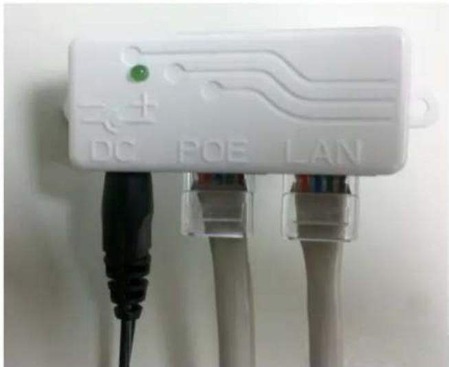
text_image
DC POE LAN
text_image
RESET ●Note.
- There is no software driver or utility installation needed.
- RJ-45 8P8C Ethernet cable is required.
- It takes about 60 seconds to complete the boot up sequence after LP-2596K powered up.
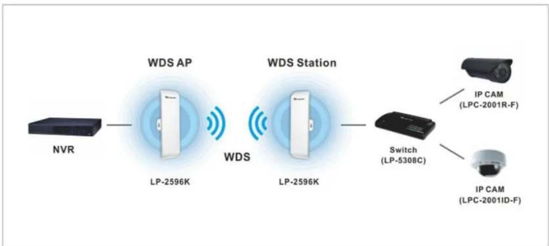
Example – Scenario for IP surveillance
The following figure indicates the basic setup to implement IP surveillance with a pair of LP-2596K. The remote monitoring image can be delivered to local NVR via the high powered, long distance transmission by LP-2596K.
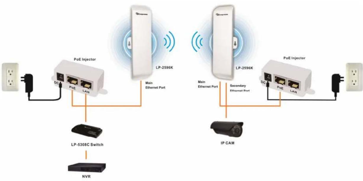
flowchart
graph TD
    A["Power Supply"] --> B["Switch"]
    B --> C["PoE Injector"]
    C --> D["LP-2596K"]
    D --> E["Main Ethernet Port"]
    E --> F["IP CAM"]
    F --> G["PoE Injector"]
    G --> H["DC"]
    G --> I["PoE"]
    G --> J["LAN"]
    C --> K["DC"]
    C --> L["PoE"]
    C --> M["LAN"]
    D --> N["LP-5308C Switch"]
    G --> O["Secondary Ethernet Port"]
    G --> P["IP CAM"]
Chapter 3 Software Configuration
System Requirements:
- Microsoft Windows XP/Vista/7/8, Mac iOS, Linux
- A Web Browser supports HTTP such as Internet Explorer, Google Chrome, Safari, and Mozilla Firefox etc.
Network Connection Setup:
The default IP of LP-2596K is 192.168.1.200. You have to make sure your computer is on the same network segment as LP-2596K before connecting to LP-2596K.
Example: In the Windows 7 operating system
- Press Start and enter ncpa.cpl in search bar. You will see network connection page.
- Select your network interface card and Right click to set Properties.
- Double click Internet Protocol Version 4 (TCP/IPv4).
- Select Specify an IP address and enter the IP address.
IP Address: 192.168.1.x (x can be any number between 1 to 254 except for 200)
Subnet Mask: 255.255.255.0
Default Gateway: 192.168.1.200
- Click OK to complete the IP setting.

text_image
Internet Protocol Version 4 (TCP/IPv4) Properties General You can get IP settings assigned automatically if your network supports this capability. Otherwise, you need to ask your network administrator for the appropriate IP settings. Obtain an IP address automatically Use the following IP address: IP address: 192 . 168 . 1 . 100 Subnet mask: 255 . 255 . 255 . 0 Default gateway: 192 . 168 . 1 . 200 Obtain DNS server address automatically Use the following DNS server addresses Preferred DNS server: . Alternate DNS server: . Validate settings upon exit Advanced... OK CancelGet started with LP-2596K
- Open Web browser and enter 192.168.1.200 in the URL field of Web browser.

http://192.168.1.200/

- Enter "admin" as default user name, and "admin" as default password.

text_image
Windows Security The server 192.168.1.200 at . requires a username and password. Warning: This server is requesting that your username and password be sent in an insecure manner (basic authentication without a secure connection). User name Password Remember my credentials OK CancelAfter successful login, you'll see the system status shown as below.
| ✓ Network Operation Mode LAN Setup QoS Setup Static Routes | Status | Refresh | |
| Radio Band: 11NAHT40 Mode: AP Encryption: None SSID: 2596K Current Frequency: 5.18 GHz MAC Address: 00:1a:ef.00:01:29 Current TX Power: 27 dBm Link Status: Check Vertical TX / Horizontal TX -71 dBm / -74 dBm Vertical RX / Horizontal RX -89 dBm / -93 dBm | |||
| ✓ Radio Information Maintenance System | LAN IP Address: 192.168.1.200 Subnet Mask: 255.255.255.0 MAC Address: 00:1a:ef.00:01:28 | ||
| System System Uptime(Day Hr.Min.Sec): 00 00:40:57 Current Time(Yr-Mon-Day Hr.Min.Sec): 2013-01-01 04:55:23 Device Name: AP Hardware Version: v1.3 Software Version: v1.02.05 | |||
Web configuration of LP-2596K
Network
There're four sub-menus in Network menu including Operation Mode, LAN Setup, QoS Setup and Static Routes.
Operation Mode
Select network mode on the drop down menu and click Apply button to take it effect.
Bridge - All Ethernet ports (Main/Secondary) and wireless interface are bridged in the same network segment, so DHCP server is disabled.
Operation Mode
| Network Mode: | Bridge |
| In this mode, all ethernet ports and wireless interface are bridged together and NAT function is disabled. All the WAN related function and firewall are not supported. | |
Apply
Wireless ISP – When LP-2596K is switched to Wireless ISP mode, please also set wireless mode LP-2596K as station that means LP-2596K remotely receive broadband signal from WISP outdoor AP (base station) of Internet Service Provider (ISP). Main and Secondary Ethernet ports are bridged in the same network segment and DHCP server will be enabled.
Operation Mode
| Network Mode: | Wireless ISP ▼ |
| In this mode, all ethernet ports are bridged together and the wireless client will connect to ISP access point. The NAT is enabled and PCs in ethernet ports share the same IP to ISP through wireless LAN.You must set the wireless to client mode first and connect to the ISPAp in SiteSurvey page. | |
Apply
LAN Setup
You can configure LAN (secondary) including IP and DHCP on this page.
LAN
| IP Address: | 192 . 168 . 1 . 200 |
| Subnet Mask: | 255 . 255 . 255 . 0 |
| Gateway: | 0 . 0 . 0 . 0 |
| DHCP Server: | Disable ▼ Show Clients |
| Spanning Tree Protocol: | Disable ▼ |
| Domain Name: | Loopcomm |
| Device Name: | LP-2596K |
| DHCP Client IP Range Start: | 192 . 168 . 1 . 100 |
| DHCP Client IP Range End: | 192 . 168 . 1 . 200 |
| DHCP Client MAX Leases: | 100 (1 to 254) |
| DHCP Client Lease Time: | 864000 (864000 to 8640000 seconds) |
Apply
Note.
- When spanning tree protocol (STP) enabled, it will eliminate bridging loops across the LAN interfaces.
- DHCP server is disabled in condition of the bridge operation mode, otherwise it's enabled as default when LP-2596K operates in Wireless ISP mode.
QoS Setup
Quality of service (QoS) is especially used for network traffic/bandwidth control with specific requirements such as Video Streaming in IP surveillance application.
QoS Setup
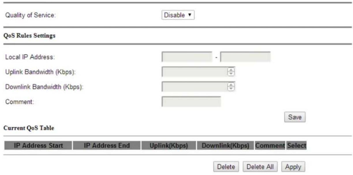
text_image
Quality of Service: Disable QoS Rules Settings Local IP Address: - Uplink Bandwidth (Kbps): Downlink Bandwidth (Kbps): Comment: Current QoS Table IP Address Start IP Address End Uplink(Kbps) Downlink(Kbps) Comment Select Delete Delete All ApplyStatic Routes
Static routing is a network routing method that builds up the connection by manually-configured routing entry. In most cases, static routes are usually manually configured by a network administrator by adding in entries into a routing table.
Static Routes
| ID | Enable | IP Address | Netmask | Gateway IP | Comment |
| 1 | No ▼ | ||||
| 2 | No ▼ | ||||
| 3 | No ▼ | ||||
| 4 | No ▼ | ||||
| 5 | No ▼ | ||||
| 6 | No ▼ |
Note. It will be enabled when operation mode is switched to Wireless ISP.
Radio
There're four sub-menus in Radio menu including Basic Settings, Advanced Settings, Security and MAC Address Control.
Basic Setting
This page contains essential wireless network settings as follows:
Basic Settings
| Band: | 5G 11NA HT40 ▼ | |
| Channel: | 36 -5180MHz ▼ | |
| Data Rate: | Auto ▼ | |
| Mode: | Access Point ▼ | SiteSurvey |
| SSID: | LP-2596K | |
| Suppress SSID: | Disable ▼ | |
| Country code: | USA ▼ | |
| Change MAC Address: | Disable ▼ | |
| MAC Address: | 00:00:00:00:00:00 | |
| Transmission Distance: | ■ | 1 km |
Apply
| Band Click to select wireless band from pull down menu. | |
| Channel | Select the wireless communication frequency/channel from pull-down menu. |
| Data Rate | Defines the data rate (in Mbps) at which the device should transmit wireless packets. You can fix a specific data rate between MCS 0 and MCS 7 (or MCS 15 for 2x2 chain devices). |
| Mode | Click to select wireless mode (AP/ Station/ WDS+AP/ WDS+Station) from drop-down menu. |
| SSID | It is the wireless network name. The SSID can be 32 bytes long.User can use the default SSID or change it. |
| Suppress SSID Enable or disable the SSID broadcast function. | |
| Country Code Choose your own country. | |
| Change MAC Address When the router operates as station mode, sometimes you will see the multiple SSID of many AP will be likely the same. In this condition, you can connect the required SSID and then enter its MAC address to keep the connection constant, even if reconnect it next time. | |
| Transmission Distance | Changing the distance value will change the ACK (Acknowledgement) timeout value accordingly, so it means the distance should be set as real distance between LP-2596K and other device for accurate transmission performance. |
Note. WDS (wireless distribution system) is a wireless interconnection system of access points in an IEEE 802.11 network. It allows wireless network coverage to be expanded with multiple access points. The condition of WDS AP mode should be set as the same channel, encryption, and IP/network segment.
Advanced Setting
In Advanced setting, there're further wireless network configurations for whom needs to adjust in transmission.
Advanced Settings

text_image
Transmit Power: 25 dbm Cilent Isolation: Disable DFS: Disable RTS/CTS Threshold: 0 bytes Beacon Interval: 100 milliseconds DTIM: 1 Software Retry Tx: 3 Roaming Threshold: -94 dBm Short GI: 800 ns Fragment Size: 2346 bytes Aggregation: Enable Aggregated Frames Number: 32 Maximum Aggregated Size: 50000 Tx ChainMask: 2 Chain Rx ChainMask: 2 Chain PoE Pass Through: OFF SetApply
| Transmit Power Defines the | the maximum average transmit output power (in dBm) of the device. The transmit power level maximum is limited according to country regulations. |
| RTS/CTS Determines the | packet size of a transmission and, through the use |
| Threshold of an AP, helps | control traffic flow. The range is 0-2346 bytes. |
| Beacon Interval Beacons | are the packets sending by Access point to synchronize the wireless network. The beacon interval is the time interval between beacons sending by this unit in AP or AP+WDS operation. The default and recommended beacon interval is 100 milliseconds. |
| DTIM This is the Delivery | Traffic Indication Map. It is used to alert the clients that multicast and broadcast packets buffered at the AP will be transmitted immediately after the transmission of this beacon frame. You can change the value from 1 to 255. The AP will check the buffered data according to this value. For example, selecting “1” means to check the buffered data at every beacon. |
| Roaming Threshold Defines | the minimum client signal level accepted by the AP for the client to connect. |
| Short GI Guard intervals are used to ensure that distinct transmissions do not interfere with one another. Only effect under Mixed Mode. | |
| Fragment Size A large data frame is fragmented into several fragments each of size equal to fragment threshold. By tuning the fragment threshold value, we can get varying fragment sizes. | |
| Aggregation A part of the 802.11n standard that allows sending multiple frames per single access to the medium by combining frames together into one larger frame. It creates the larger frame by combining smaller frames with the same physical source, destination end points, and traffic class (QoS) into one large frame with a common MAC header | |
| Aggregated Frames Number | Determines the number of frames combined in the new larger frame. |
| Maximum Aggregation Size | Determines the size (in bytes) of the larger frame. |
| Tx/Rx Chain Mask | Displays the number of independent spatial data streams the device is transmitting (TX) and receiving (RX) simultaneously within one spectral channel of bandwidth. Multiple chains increase data transfer performance significantly. |
| PoE Pass Through | It allows Secondary Ethernet port to provide 24V power for a secondary device when it enabled. |
Security
The security setting includes WEP and WPA encryption with enhanced options.
Security Settings
Encryption: None ▼
None
No security applied
Apply
WEP
WEP (Wired Equivalent Privacy) is the basic security algorithm for data encryption and supports 64/104/128 bits length.
Security Settings
Encryption: WEP ▼
WEP
Simple WEP Security
WEP Mode:
Open ▼
Key Length:
64-bit ▼
Key 1
ASCII (5 characters)
Key 2
ASCII (5 characters)
Key 3
ASCII (5 characters)
Key 4
ASCII (5 characters)
Apply
WPA
Wi-Fi Protected Access (WPA) and Wi-Fi Protected Access II (WPA2) developed by the Wi-Fi Alliance are two advanced security protocols, and it's popular used in securing wireless computer networks.
Security Settings
Encryption: WPA ▼
WPA
WPA Mode:
WPA ▼
Enhanced Security for:
Personal Shared Key (Preshared Key) ▼
Preshared Key:
(8 to 63 characters)
Cipher:
TKIP ▼
Apply
| Enhanced Security Specify one of the following WPA key selection methods. | |
| Preshared Key | Specify a passphrase. The preshared key is an alphanumeric password between 8 and 63 characters long. |
| Cipher | Select TKIP, AES, or AUTO for WPA algorithms. |
MAC Address Control
The MAC Address Control will allow/deny any AP client connect to router.
MAC Access Control
MAC Access Control:
Disable
MAC Address:
Add
Apply
| MAC Access Control | MAC access control is implemented using an IP tables (routing) firewall that protects the resources of a private network from outside threats by preventing unauthorized access and filtering specified types of network communication. |
| MAC address The network | device identified by its MAC address. |
Information
There're five sub-menus in Information menu including Status, Statistics, Association List, Memory Utilization, and Routes.
Status
It shows the present overview of LP-2596K system configurations..
| Status | Refresh | |
| Radio | ||
| Band: | 11NAHT40 | |
| Mode: | AP | |
| Encryption: | None | |
| SSID: | LP-2596K | |
| Current Frequency: | 5.18 GHz | |
| MAC Address: | 00:1a:ef.42:6f.5a | |
| Current TX Power: | 25 dBm | |
| Link Status: | Check | |
| LAN | ||
| IP Address: | 192.168.1.200 | |
| Subnet Mask: | 255.255.255.0 | |
| MAC Address: | 00:1a:ef.42:6f.59 | |
| System | ||
| System Uptime(Day Hr.Min:Sec): | 00 00:23:36 | |
| Current Time(Yr-Mon-Day Hr.Min:Sec): | 2013-01-01 03:42:02 | |
| Device Name: | LP-2596K | |
| Hardware Version: | v1.3 | |
| Software Version: | v1.02.08 | |
Statistics
It shows the statistic data flow of Wireless and LAN interface in LP-2596K.
Statistics
| Wireless | ||||
| bytes | packets | errors | drop | |
| Receive: | 0 | 0 | 0 | 0 |
| Transmit: | 0 | 0 | 0 | 510 |
| LAN | ||||
| bytes | packets | errors | drop | |
| Receive: | 240675 | 2369 | 0 | 38 |
| Transmit: | 654899 | 2010 | 0 | 0 |
Refresh Reset
Association List
It shows which device and its connection information to LP-2596K.
Association
| MAC Address | Channel | Tx Rate (Mbps) | Signal Strength (dbm) |
| Refresh |
Memory Utilization
It presents the status of LP-2596K memory utilization.
Memory Utilization

bar_stacked
| Category | Blue Segment (%) | Gray Segment (%) | Total Available (KB / 65536 KB) | | :--- | :--- | :--- | :--- | | Total Available: | 73 | 47844 | 47844 | | Used: | 18 | 8956 | 8956 | | Free: | 80 | 38720 | 38720 | | Buffers: | 0 | 0 | 0 | | Cached: | 26 | 2368 | 2368 |Refresh
Routes
It presents LP-2596K device route.
Routes
Destination Gateway Genmask Flags Metric Ref Use Iface 192.168.1.0 0.0.0.0 255.255.255.0 U 0 0 0 br0
Refresh
Note. It will be enabled when operation mode is switched to Wireless ISP.
Maintenance
In Maintenance, it contains of Account and Firmware Upgrade submenu.
Account
It allows user to change password setting.
Password Setup
| User name: | admin |
| Old password: | |
| New password: | |
| Confirm new password: |
Apply
Firmware Upgrade
Click the Browse button to select the new firmware image file on PC. And click the Upgrade button to upgrade firmware.
Firmware Upgrade
| Select file: | Browse... | Upgrade |
Note. Please do not take off the power or remove the Ethernet cable connected to LP-2596K when firmware upgrade is in process. Otherwise, it will probably cause system crush.
System
There're four parts in System menu including Backup Settings, Time Settings, Service Settings and Log.
Backup Settings
It consists of Back Up configuration, Restore Configuration, System Reboot and System Reset.
Miscellaneous
| Back Up Configuration: | Save |
| Restore Configuration: | Upload |
| System Reboot: | Reboot |
| Reset device to factory default: | Reset |
Time Settings
Time Settings
| Current Time: | 2013-01-01 05:32:10 Refresh | |||||
| SNTP Client: | Disable ▼ | |||||
| SNTP Server IP : | 64 . 90 . 182 . 55 | |||||
| Time Zone : | GMT ▼ | |||||
| System Time Setup: | Year Month Day Hour Minute Second | |||||
| 2014 ▼ 02 ▼ 12 ▼ 19 ▼ 58 ▼ 49 ▼ | ||||||
Save
| SNTP Client Enable or Disable SNTP Client function. | |
| SNTP Server IP Enter the | IP address of SNTP server. |
| Time Zone Select the time | zone in your country from pull-down menu. |
Service Settings
It includes SNMP configuration, HTTPS secure connection, Telnet, and SSH setting.
Services Settings
SNMP Configuration

text_image
Read Community: public Write Community: public Trap IP 1: 192 . 168 . 1 . 1 Trap Community 1: private System Contact: System Location:Use Secure Connection

text_image
HTTPS: Disable Secure Server Port: 443 Server Port: 80Telnet Configuration

SSH Configuration

Apply
Log
System Log
System Log
Disable ▼
System Log Server:
Disable ▼
System Log Server IP:

System Log Server Port:

Refresh
Clear
Apply
| System Log | This option enables the registration routine of system log (syslog) messages. By default it is disabled. |
| Log Server IP The host IP | address that receives syslog messages. |
| Log Server Port The TCP/IP port that receives syslog messages. | |
Compliance
Federal Communication Commission Interference Statement
This equipment has been tested and found to comply with the limits for a Class B digital device, pursuant to Part 15 of the FCC Rules. These limits are designed to provide reasonable protection against harmful interference in a residential installation. This equipment generates, uses, and can radiate radio frequency energy and, if not installed and used in accordance with the instructions, may cause harmful interference to radio communications. However, there is no guarantee that interference will not occur in a particular installation. If this equipment does cause harmful interference to radio or television reception, which can be determined by turning the equipment off and on, the user is encouraged to try to correct the interference by one or more of the following measures:
- Reorient or relocate the receiving antenna.
- Increase the separation between the equipment and receiver.
- Connect the equipment into an outlet on a circuit different from that to which the receiver is connected.
- Consult the dealer or an experienced radio/TV technician for help.
FCC Caution:
This device complies with Part 15 of the FCC Rules. Operation is subject to the following two conditions: (1) This device may not cause harmful interference, and (2) this device must accept any interference received, including interference that may cause undesired operation.
RF Radiation Exposure and Hazard Statement:
To ensure compliance with FCC RF exposure requirements, this device must be installed in a location such that the antenna of the device will be greater than 20 cm (8 in.) away from all persons. Using higher gain antennas and types of antennas not covered under the FCC certification of this product is not allowed. Installers of the radio and end users of the product must adhere to the installation instructions provided in this manual. This transmitter must not be co-located or operating in conjunction with any other antenna or transmitter.
Non-modification Statement:
Use only the integral antenna supplied by the manufacturer when operating this device.
Unauthorized antennas, modifications, or attachments could damage the TI Navigator access point and violate FCC regulations. Any changes or modifications not expressly approved by the party responsible for compliance could void the user's authority to operate this equipment.