GV-HYBRIDLPR - Security Camera Geovision - Free user manual and instructions
Find the device manual for free GV-HYBRIDLPR Geovision in PDF.


| Product Type | Security Camera |
| Brand | Geovision |
| Model | GV-HYBRIDLPR |
| Category | Hybrid LPR Camera |
| Image Sensor | 1/3" Progressive Scan CMOS |
| Resolution | Up to 2 MP (1920 x 1080) |
| Lens Type | Vari-focal, 2.8-12 mm |
| Dimensions | 150 mm x 80 mm x 70 mm |
| Weight | 0.8 kg |
| Power Supply | DC 12V / PoE (IEEE 802.3af) |
| Main Functions | License Plate Recognition (LPR), hybrid analog/IP, video analytics, motion detection, privacy masking |
| Video Compression | H.265, H.264, MJPEG |
| Interface | BNC analog input, RJ45 IP output |
| Infrared Range | Up to 30 meters |
| Weather Rating | IP66 |
| Maintenance | Clean lens with soft dry cloth; check cable connections regularly |
| Safety | Use certified power adapter; avoid exposure to moisture |
| Spare Parts | Lens, IR LEDs, power adapter available |
| General Information | ONVIF compliant; supports GV-VMS software |
Frequently Asked Questions - GV-HYBRIDLPR Geovision
User questions about GV-HYBRIDLPR Geovision
0 question about this device. Answer the ones you know or ask your own.
Ask a new question about this device
Download the instructions for your Security Camera in PDF format for free! Find your manual GV-HYBRIDLPR - Geovision and take your electronic device back in hand. On this page are published all the documents necessary for the use of your device. GV-HYBRIDLPR by Geovision.
USER MANUAL GV-HYBRIDLPR Geovision
natural_image
Exterior view of two GeoVision security cameras with visible camera modules and no text or symbols on the device itself.
GeoVision
© 2014 GeoVision, Inc. All rights reserved.
Under the copyright laws, this manual may not be copied, in whole or in part, without the written consent of GeoVision.
Every effort has been made to ensure that the information in this manual is accurate. GeoVision, Inc. makes no expressed or implied warranty of any kind and assumes no responsibility for errors or omissions. No liability is assumed for incidental or consequential damages arising from the use of the information or products contained herein. Features and specifications are subject to change without notice.
GeoVision, Inc.
9F, No. 246, Sec. 1, Neihu Rd.,
Neihu District, Taipei, Taiwan
Trademarks used in this manual: GeoVision, the GeoVision logo and GV series products are trademarks of GeoVision, Inc. Windows and Windows XP are registered trademarks of Microsoft Corporation.
May 2014
Preface
Welcome to the GV-Hybrid LPR Camera 20R / 10R / GV-IP LPR Camera 5R User's Manual.
The GV-IP LPR Camera has a series of models designed to meet different needs. This manual is designed for the following models and firmware versions:
| Models Firmware Version | |
| GV-Hybrid LPR Camera 20R 1.02 | |
| GV-Hybrid LPR Camera 10R 1.02 | |
| GV-IP LPR Camera 5R 1.0 |
Contents
Naming Definition....v
Options ...... v
Note for Connecting to GV-System......vi
Note for Installing Camera Outdoor......vii
Note for Adjusting GV-Hybrid LPR Camera 20R ......viii
Chapter 1 Introduction....1
1.1 GV-Hybrid LPR Camera 20R /10R....1
1.1.1 Features 2
1.1.2 System Requirements....3
1.1.3 Packing List 4
1.1.4 Overview....5
1.1.5 Device Installation....6
1.1.6 Connecting the Camera....10
1.2 GV-IP LPR Camera 5R 14
1.2.1 Features 15
1.2.2 System Requirements....16
1.2.3 Packing List 17
1.2.4 Overview....18
1.2.5 Device Installation....19
1.2.6 Connecting the Camera 20
1.2.7 Adjusting the Angles .....21
1.2.8 Replacing the Silica Gel Bag....24
1.2.9 Installing the Sun-Shield Cover 25
Chapter 2 Getting Started ....26
2.1 Looking Up the IP Address....26
2.2 Accessing Your Surveillance Images 29
2.3 Configuring the Basics 30
Chapter 3 Guest Mode and Live View Panel....31
3.1 The Live View Window....32
3.2 The Control Panel of the Live View Window 34
3.3 Snapshot of a Live Video 37
3.4 Video Recording 37
3.5 Picture-in-Picture and Picture-and-Picture View....38
3.6 Alarm Notification....40
3.7 Video and Audio Configuration....41
3.8 Remote Configuration....42
3.9 Camera Name Display....42
3.10 Image Enhancement....42
Chapter 4 Administrator Mode ....43
4.1 Video & Motion 45
4.1.1 Video Settings....46
4.1.2 Motion Detection....51
4.1.3 Privacy Mask 52
4.1.4 Text Overlay....53
4.1.5 Tampering Alarm....54
4.2 Events & Alerts 56
4.2.1 E-mail 57
4.2.2 FTP....59
4.2.3 Center V2....61
4.2.4 VSM....63
4.2.5 Backup Center 65
4.2.6 GV-Video Gateway / GV-Recording Server 67
4.2.7 ViewLog 69
4.2.8 RTSP 70
4.3 Monitoring....71
4.3.1 GV-Hybrid LPR Camera 20R / 10R 71
4.3.2 GV-IP LPR Camera 5R 72
4.4 Recording Schedule 73
4.4.1 Recording Schedule Settings 73
4.5 Network 74
4.5.1 LAN Configuration....74
4.5.2 Advanced TCP/IP 76
4.5.3 IP Filtering....80
4.5.4 SNMP Settings....81
4.6 Management 83
4.6.1 Date and Time Settings....83
4.6.2 GPS Maps Settings....85
4.6.3 Storage Settings 87
4.6.4 User Account 90
4.6.5 Log Information....91
4.6.6 System Log....92
4.6.7 Tools 94
4.6.8 Language....96
Chapter 5 Advanced Applications....97
5.1 Upgrading System Firmware....97
5.1.1 Using the Web Interface....98
5.1.2 Using the GV-IP Device Utility 99
5.2 Backing Up and Restoring Settings....102
5.3 Restoring to Factory Default Settings....104
5.3.1 Using the Web Interface....104
5.3.2 Directly on the Camera 104
5.4 Verifying Watermark....105
5.4.1 Accessing AVI Files....105
5.4.2 Running Watermark Proof....105
5.4.3 The Watermark Proof Window 106
Chapter 6 DVR Configurations ......107
6.1 Setting Up IP Cameras 109
6.1.1 Customizing Camera Settings.... 112
6.2 Remote Monitoring with Multi View 114
6.3 Remote Monitoring with E-Map.... 116
Chapter 7 CMS Configurations....118
7.1 Center V2 118
7.2 VSM....120
7.3 Dispatch Server 121
Chapter 8 Smart Device Connection....122
8.1 Android 123
8.1.1 Connecting to the Camera 123
8.1.2 Accessing Live View 126
8.2 Apple 128
8.2.1 Connecting to the Camera 129
8.2.2 Accessing Live View 130
Specifications....132
GV-Hybrid LPR Camera 20R / 10R 132
GV-IP LPR Camera 5R 136
Appendix....139
A. The CGI Command....139
B. RTSP Protocol Support....140
C. Settings for Internet Explorer 8 or later 141
Naming Definition
| GV-System | GeoVision Analog and Digital Video Recording Software. The GV-System also refers to Multicam System, GV-NVR System, GV-DVR System and GV-Hybrid DVR System at the same time. |
Options
Optional devices can expand your camera's capabilities and versatility. Contact your dealer for more information.
| Device Description | |
| GV-PA191 PoE Adapter | The GV-PA191 PoE adapter is designed to provide power and network connection to the cameras over a single Ethernet cable. The GV-PA191 PoE adapter is only available for GV-IP LPR Camera 5R. |
| GV-PoE Switch | The GV-POE Switch is designed to provide power along with network connection for IP devices. The GV-POE Switch is available in various models with different numbers and types of ports. |
Note for Connecting to GV-System
The GV-Hybrid LPR Camera 20R / 10R / GV-IP LPR Camera 5R is designed to work with and record on GV-System, a hybrid or digital video management system.
Once the camera is connected to the GV-System, the resolution set on the GV-System will override the resolution set on the camera's Web interface. You can only change the resolution settings through the Web interface when the connection to the GV-System is interrupted.
Note for Installing Camera Outdoor
When installing the GV-Hybrid LPR Camera 20R / 10R / GV-IP LPR Camera 5R outdoor, mind the following:
- Set the camera above the junction box to prevent water from entering the camera along the cables.
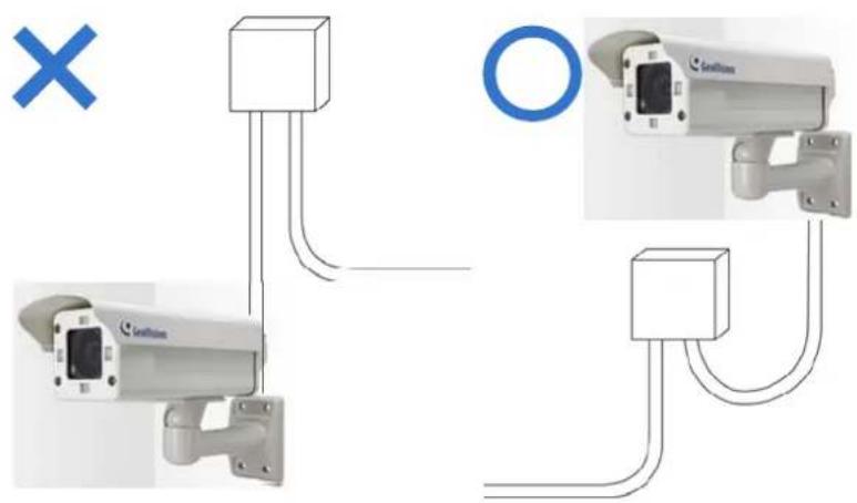
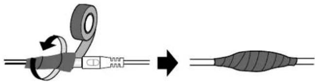
- Waterproof the PoE, power and TV-out cables with waterproof silicon rubber or the like.
natural_image
Diagram showing a cable being twisted with a tape, resulting in a striped cable (no text or symbols present)-
To prevent the lens from fogging up, replace the silica gel bag every time you open the camera, and conceal the gel bag in camera within 2 minutes of exposing to open air. The silica gel bag loses it effectiveness when the dry camera is opened.
-
For each newly replaced silica gel bag, allow it to absorb moisture for at least 5 hours before operating the camera.
-
The camera casing can be hot due to its IR LED. Make sure you unplug the power cable and allow the camera casing to cool down before handling the camera.
Note for Adjusting GV-Hybrid LPR Camera 20R
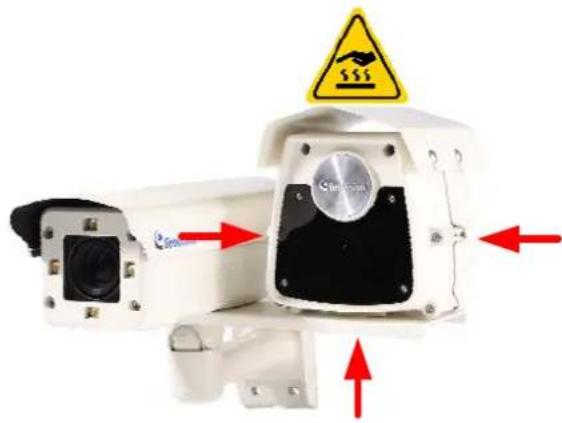
During the operation of the GV-Hybrid LPR Camera 20R, the external IR Illuminator is at the high temperature of up to 50°C (122°F). When adjusting the camera angle or reinstalling the camera, avoid touching the surface of the external IR Illuminator.
natural_image
Close-up of a surveillance camera with red arrows indicating sensor movement, no visible text or symbolsChapter 1 Introduction
1.1 GV-Hybrid LPR Camera 20R / 10R
natural_image
Exterior view of a modern security camera with visible lens and control panel (no text or symbols on body)GV-Hybrid LPR Camera 20R
natural_image
Exterior view of a GeoVision surveillance camera (no text or symbols visible on body)GV-Hybrid LPR Camera 10R
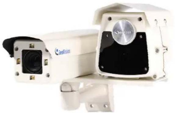
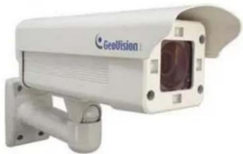
The GV-Hybrid LPR Camera 20R, with an external IR Illuminator, is a 1.3 MP B/W network camera designed solely for recognition of reflective license plates on vehicles traveling at 120 km/hr (75 mph) or less. Equipped with an external IR Illuminator which allows the maximum IR distance of 22 m (72.2 ft), the camera is able to produce clear license plate capture for one lane under low-light conditions. It is also able to work in environments with extreme temperatures from as low as -40^ (-40°F) up to 50^ (122°F).
The GV-Hybrid LPR Camera 10R is a 1.3 MP B/W network camera designed solely for recognition of reflective license plates on vehicles traveling at 120 km/hr (75 mph) or less. With its high-power LEDs and intelligent IR, the camera is able to automatically adjust its shutter speed to the scene and produce clear license plate capture under low-light conditions. Under certain conditions, the GV-Hybrid LPR Camera 10R can capture up to two lanes in a single shot. It is also able to work in environments with extreme temperatures from as low as -40°C (-40°F) up to 50°C (122°F).
The GV-Hybrid LPR Camera 20R / 10R can be easily configured through its Web interface and you can record and play back recordings using the free GV-NVR software included in the standard package.
1.1.1 Features
• 1.3 megapixel B/W progressive scan CMOS
• Dual streams from MJPEG or H.264
- Up to 30 fps at 1280 x 1024
• Recognition for reflective License Plate only
• Maximum Speed 120 km/h (75 mph)
- Ingress protection (IP67)
• Vandal Resistance (IK10)
• Maximum IR distance 22 m (72.2 ft.) (for GV-Hybrid LPR Camera 20R only)
• Maximum IR distance 12 m (39.4 ft.) (for GV-Hybrid LPR Camera 10R only)
• Built-in heater and fan
- Support for TV-out
- Two-way audio
- Defog
- Motion detection
- Tampering alarm
- Privacy mask
- Text overlay
- IP address filtering
• Power supplied through PoE (IEEE 802.3 at)
• Support for iPhone, iPad, Android and 3GPP
• ONVIF (Profile S) conformant
• 31 languages on Web interface
1.1.2 System Requirements
To access the camera functions and settings through Web browser, ensure your PC is in good network connection and use one of the following Web browsers:
• Microsoft Internet Explorer 7.x or later
- Google Chrome
- Mozilla Firefox
- Safari
Note:
- For users of Internet Explorer 8 or later, additional settings are required. For details, see Appendix C.
- With non-IE browsers,
A. Motion Detection, Text Overlay, two-way audio and GPS map settings are not supported.
B. The Play function is only available on the live view window (Figure 3-2).
C. RTSP streaming must be kept as enabled. For more details, see 4.3.8 RTSP / 3GPP.
Compatible Software Version
| Model Firmware Version GV-System Version | ||
| GV-Hybrid LPR Camera 20R V1.02 V8.5.7.0 | ||
| GV-Hybrid LPR Camera 10R | V1.00 | V8.5.5.0 |
| V1.01 | V8.5.7.0 | |
| V1.02 | ||
1.1.3 Packing List
• GV-Hybrid LPR Camera 20R / 10R
- Iron Screw Anchor x 4 (for GV-Hybrid LPR Camera 20R only)
- Plastic Screw Anchor x 4 (for GV-Hybrid LPR Camera 10R only)
- Expansion Screw x 4 (for GV-Hybrid LPR Camera 20R only)
- Screw x 4 (for GV-Hybrid LPR Camera 10R only)
- Washer x 4
- Big Torx Wrench
- Small Torx Wrench
- Sun-Shield Cover
- Silica Gel Bag x 2 (1 already installed)
- Sticker x 2
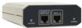
• GV-PA481 PoE Adapter
• GV-PA481 Power Cord
• GV-IP LPR Camera Software CD
• GV-NVR Software DVD
• GV-ASManager Software DVD
1.1.4 Camera Overview
To access the functional panel of the GV-Hybrid LPR Camera 20R / 10R, follow the section below to remove its camera cover first.
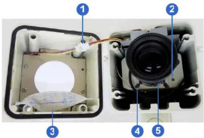
Figure 1-1
| No. | Name | Description |
| 1 IR | power plug | Supplies power to the built-in IR LEDs. |
| 2 Status | LED | Turns on when the unit is ready for use. |
| 3 Silica gel bag | keeps | the camera housing dry. |
| 4 Zoom Screw | Adjusts | the zoom of the camera. |
| 5 Focus Screw | Adjusts | the focus of the camera. |
1.1.5 Device Installation
1.1.5.1 Installation Guidelines
To produce quality image and to avoid software recognition errors, make sure you adhere to the guidelines when installing your GV-Hybrid LPR Camera 20R / 10R. See GV-LPR Camera Installation Guide.
1.1.5.2 Installing the Camera
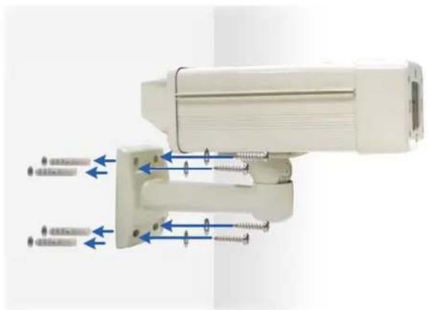
After you have read through the installation guides and chosen an installation site, follow the steps below to install the GV-Hybrid LPR Camera 20R / 10R. Here we use the GV-Hybrid LPR Camera 10R as the example.
- Mark the installation site and drill four holes for screw anchors.
- Insert the supplied screw anchors.
- Secure the camera to the wall using the supplied washers and screws.
natural_image
White medical device with blue arrows indicating force or movement, mounted on a vertical support (no text or symbols visible)Figure 1-2
- Connect the camera to the network and supply power via the PoE cable. See 1.6 Connecting the Camera.
-
Access the live view. See 2.1 Accessing the Live View.
-
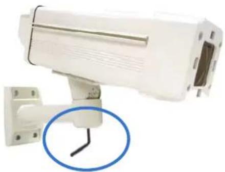
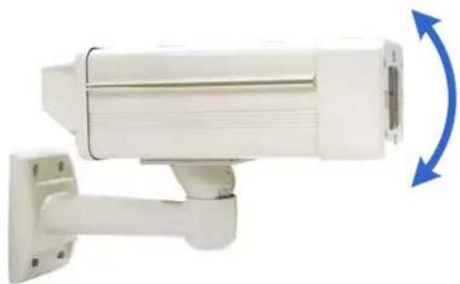
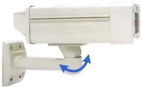
Based on the live view, adjust the angle of the camera. Loosen the indicated screw with the supplied big torx wrench and adjust the joint.
natural_image
White surveillance camera mounted on a wall, with a blue circular annotation highlighting the cable (no text or symbols present)Figure 1-3
Tilt Adjustment
natural_image
White surveillance camera with mounted sensor and wall-mounted cable, showing blue directional arrow (no text or symbols)Figure 1-4
Pan Adjustment
natural_image
White surveillance camera mounted on a wall-mounted base, showing a blue directional arrow indicating rotation (no text or symbols visible)Figure 1-5
- Based on the live view, adjust the focus and zoom of the camera.
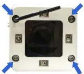
A. Unscrew the cover with the supplied small torx wrench.
natural_image
Close-up of a small electronic device with a central black square and blue directional arrows pointing to its top (no text or symbols visible)Figure 1-6
B. Hold the connectors and unplug them.
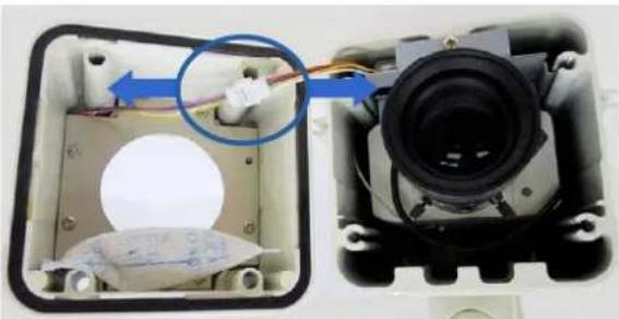
natural_image
Interior view of a device showing a camera lens mounted inside a transparent enclosure, with a blue arrow indicating the cable direction (no text or symbols visible)Figure 1-7
Important:
-
Unscrew and remove the cover carefully. Pulling the cover off may cause damages to the inner wiring of the camera.
-
To prevent the live view from being darkened when the cover is removed, see LPR Setting in 4.1.1 Video Setting.
C. Adjust the focus and zoom.
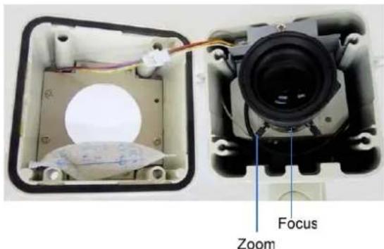
Figure 1-8
- Replace the silica gel bag. Paste the sticker to the front side of the silica gel bag. Press the sticker several times to make sure it adheres properly. Paste the silica gel bag to the indicated place.
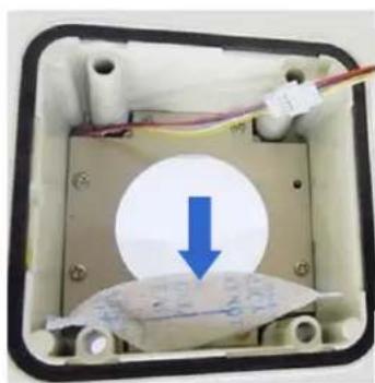
natural_image
Interior view of an electronic device showing a circular component with a blue downward arrow and wire, no visible text or symbols.Figure 1-9
Important:
- Be sure that the silica gel bag is concealed in the camera housing within 2 minutes of exposing to open air.
- To prevent the lens from fogging up, you must replace the silica gel bag every time you open the camera. The gel bag loses its effectiveness when the dry camera is opened.
-
For each newly replaced silica gel bag, allow it to absorb moisture for at least 5 hours before operating the camera.
-
Refer to step 7 to plug the connectors and secure the camera cover.
1.1.6 Connecting the Camera
Follow the steps below to connect your GV-Hybrid LPR Camera 20R / 10R.
1.1.6.1 GV-Hybrid LPR Camera 20R
- Optionally connect a speaker to the green RCA wire and an external microphone to the pink RCA wire.
- Optionally connect a monitor to the black BNC wire. Enable the TV-Out function by selecting the correct signal format at the TV Out field on the Web interface. See 4.1.1 Video Settings.
- Connect the camera's cable to the GV-PA481 PoE adapter as illustrated below. The power and network will be supplied simultaneously.
- Connect the external IR Illuminator's cable to the power source.
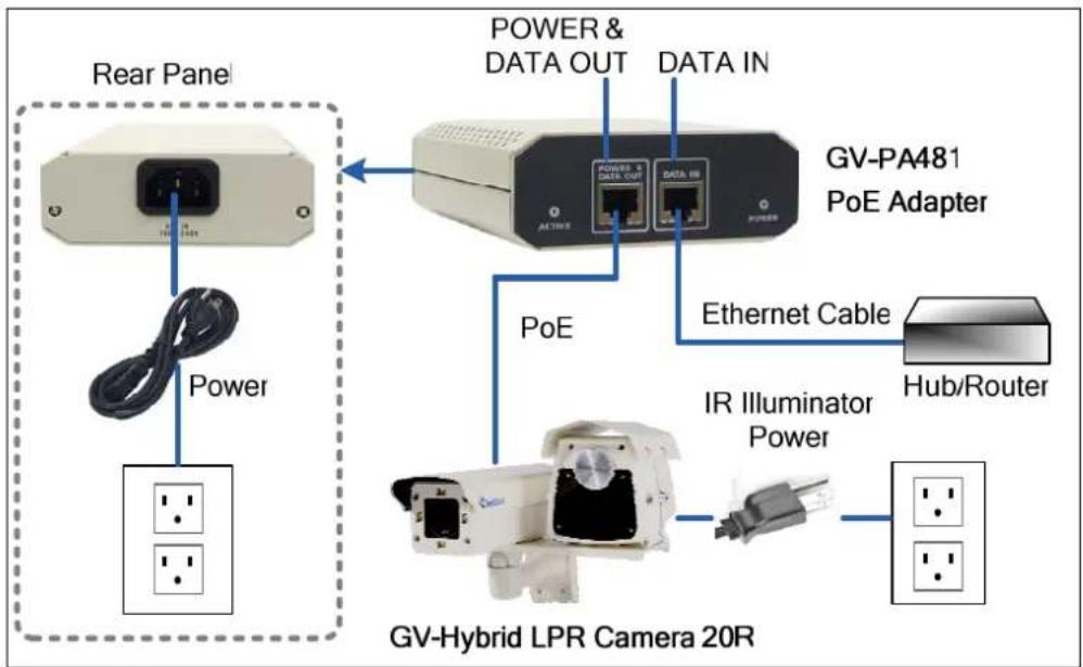
flowchart
graph TD
    A["Rear Panel"] -->|Power| B["Power"]
    A --> C["GV-Hybrid LPR Camera 20R"]
    C --> D["GV-PA481 PoE Adapter"]
    D -->|PoE| E["POWER & DATA OUT"]
    D -->|PoE| F["Data IN"]
    D -->|Ethernet Cable| G["Hub/Router"]
    C --> H["IR Illuminator Power"]
Figure 1-10
- When the status LED of the camera is on, .you are ready to access the live view, adjust the image clarity and configure the basics. See Getting Started, Chapter 2.
CAUTION: The surface of the external IR Illuminator is at the high temperature of up to 50°C (122°F) during operation of the GV-Hybrid LPR Camera 20R.
1.1.6.2 GV-Hybrid LPR Camera 10R
- Optionally connect a speaker to the green RCA wire and an external microphone to the pink RCA wire.
- Optionally connect a monitor to the black BNC wire. Enable the TV-Out function by selecting the correct signal format at the TV Out field on the Web interface. See 4.1.1 Video Settings.
- Connect the camera's cable to the GV-PA481 PoE adapter as illustrated below. The power and network will be supplied simultaneously.
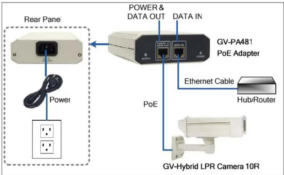
flowchart
graph TD
    A["Rear Panel"] -->|Power| B["Power"]
    A --> C["LV/DC"]
    A --> D["Ground"]
    B --> E["GV-Hybrid LPR Camera 10R"]
    E --> F["PoE"]
    F --> G["GV-PA481 PoE Adapter"]
    G --> H["POWER & DATA OUT"]
    G --> I["DATA IN"]
    G --> J["Ethernet Cable"]
    G --> K["Hub/Router"]
Figure 1-11
- When the status LED of the camera is on, .you are ready to access the live view, adjust the image clarity and configure the basics. See Getting Started, Chapter 2.
1.1.6.3 Wire Definition
GV-Hybrid LPR Camera 20R
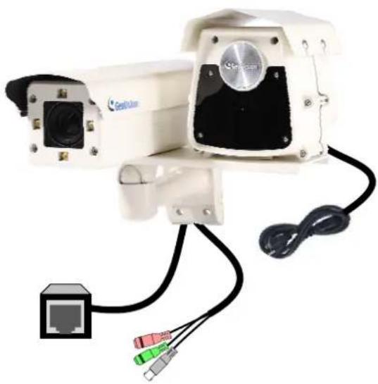
natural_image
Exterior view of a surveillance camera with attached cables and ports (no visible text or symbols)Figure 1-12
Camera
| Wire Color Definition | |
| Black (thick) PoE | |
| Black BNC TV out | |
| Green RCA Audio Out | |
| Pink RCA Audio In |
IR Illuminator
The black cable consists of three wires.
| Wire Color Definition | ||
| White | Line | Wire |
| Black | Neutral | Wire |
| Green | Ground | Wire |
GV-Hybrid LPR Camera 10R
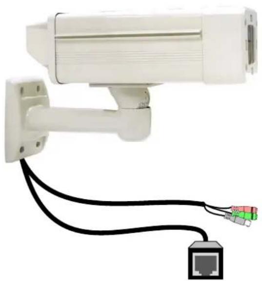
natural_image
White surveillance camera mounted on a wall with black cables and a network port terminal (no text or symbols visible)Figure 1-13
| No. Wire Color Definition | ||
| 1 | Black (thick) | PoE |
| 2 Black BNC TV out | ||
| 3 Green RCA Audio Out | ||
| 4 Pink RCA Audio In | ||
1.2 GV-IP LPR Camera 5R
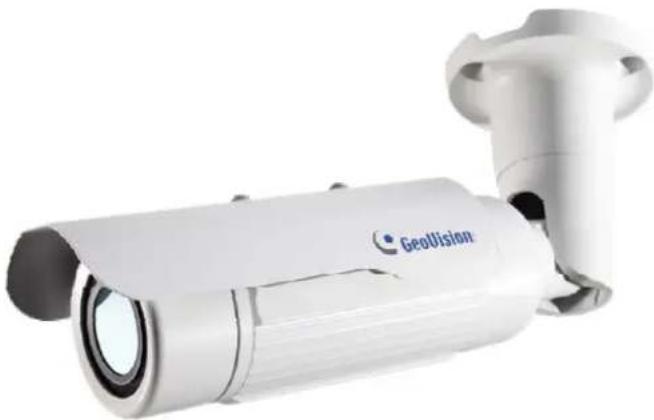
natural_image
Exterior view of a GeoVision surveillance camera (no text or symbols visible on body)Ideal for parking lot installation, the GV-IP LPR Camera 5R is a 1.3 MP B/W network camera designed for recognition of reflective license plates on vehicles traveling at 60 km/hr (37 mph) or less. With its multiple LEDs and intelligent IR, the camera is able to automatically adjust its shutter speed to the scene and produce clear license plate capture under low-light conditions. The motorized varifocal lens take the advantage of its motorized focus / zoom in that the user can remotely adjust the focus and zoom through the Web interface. It is weather proof (IP67) and also able to work in environments with temperatures ranging from -10°C (14°F) to 50°C (122°F).
The GV-IP LPR Camera 5R can be easily configured through its Web interface and you can record and play back recordings using the free GV-NVR software included in the standard package.
1.2.1 Features
• 1.3 megapixel B/W progressive scan CMOS
- Motorized varifocal lens for remote focus / zoom adjustment
• Dual streams from MJPEG or H.264
- Up to 30 fps at 1280 x 1024
• Maximum Speed 60 km/h (37 mph)
• Recognition for reflective License Plate only
- Ingress protection (IP67)
• Vandal Resistance (IK10)
• Built-In 12 IR LEDs
- Built-in fan
- Defog
- Motion detection
- Privacy mask
- Text Overlay
- IP address filtering
• Power supplied through PoE (IEEE 802.3 at)
• Support for iPhone, iPad, Android and 3GPP
• ONVIF (Profile S) conformant
• 31 languages on Web interface
1.2.2 System Requirements
To access the camera functions and settings through Web browser, ensure your PC is in good network connection and use one of the following Web browsers:
• Microsoft Internet Explorer 7.x or later
- Google Chrome
- Mozilla Firefox
- Safari
Note:
- For users of Internet Explorer 8 or later, additional settings are required. For details, see Appendix C.
- With non-IE browsers,
A. Motion Detection, Text Overlay, two-way audio and GPS map settings are not supported.
B. The Play function is only available on the live view window (Figure 3-2).
C. RTSP streaming must be kept as enabled. For more details, see 4.3.8 RTSP / 3GPP.
Compatible Software Version
| Model Firmware Version GV-System Version | |
| GV-IR LPR Camera 5R V1.00 | V8.5.8.0 |
1.2.3 Packing List
• GV-IP LPR Camera 5R
• Self Tapping Screw x 3
- Plastic Screw Anchor x 3
- Torx Wrench x 2
- Sun-Shield Cover Kit (1 Sun-Shield Cover, 2 Philips Head Screws, 2 Plastic Screw Spacers and 2 Hexagon Screws included)
• Silica Gel Bag x 2 (1 already installed)
• GV-IP LPR Camera Software CD
• GV-NVR Software DVD
• GV-ASManager Software DVD
1.2.4 Overview
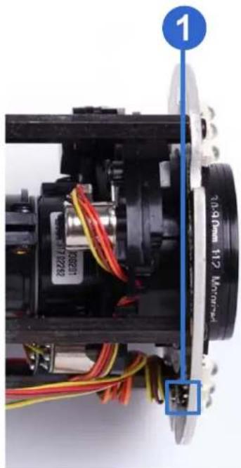
natural_image
Close-up of a mechanical assembly with visible wiring and components, no readable text or symbols present.Figure 1-14
| No. | Name | Description |
| 1 | Default | Resets all configurations of the GV-IP LPR Camera 5R to the default factory settings. See 5.3 Restoring to Factory Default Settings. |
1.2.5 Device Installation
1.2.5.1 Installation Guidelines
To produce quality image and to avoid software recognition errors, make sure you adhere to the guidelines when installing your GV-IP LPR Camera 5R. See GV-LPR Camera Installation Guide.
1.2.5.2 Installing the Camera
After you have read through the installation guides and chosen an installation site, follow the steps below to install the GV-IP LPR Camera 5R.
- Mark the installation site and drill three holes for screw anchors.
- Insert the supplied screw anchors.
- Secure the camera to the wall using the supplied screws.
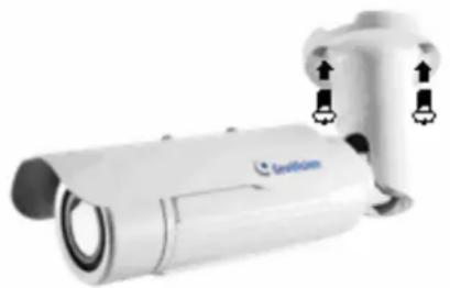
natural_image
White portable security camera with mounted sensor and control buttons (no visible text or symbols)Figure 1-15
- Remove the protection sticker from the camera's cover.
- Connect the camera to the network and supply power via the PoE cable. See 1.2.6 Connecting the Camera.
- Access the live view. See Chapter 2 Getting Started.
- Based on the live view, adjust the angle, zoom and focus of the camera of the camera. For adjusting three shafts, see 1.2.7 Adjusting the Angles. For changing zoom and focus, see Figure 1-14.
- Install the sun-shield cover to the camera. For details, see 1.2.9 Installing the Sun-Shield Cover.
1.2.6 Connecting the Camera
It is suggested to use GV-PA191 PoE Adapter to connect the GV-IP LPR Camera 5R to the network. Follow the steps below for connection.
- Connect the camera's cable to the GV-PA191 PoE Adapter as illustrated below. The power and network will be supplied simultaneously.
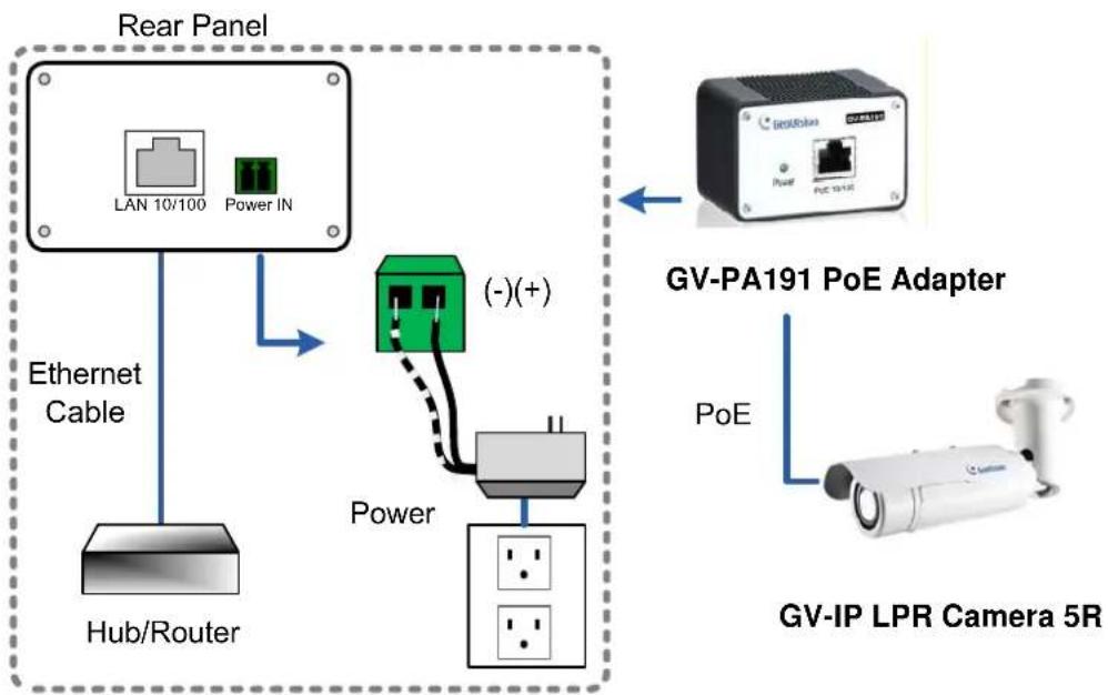
flowchart
graph TD
    A["Rear Panel"] -->|Ethernet Cable| B["Hub/Router"]
    A --> C["Power IN"]
    C --> D["(-)(+)"]
    D --> E["Power"]
    E --> F["LV"]
    G["GV-PA191 PoE Adapter"] --> H["Power"]
    I["GV-IP LPR Camera 5R"] --> J["PoE"]
    K["LAN 10/100"] --> A
Figure 1-16
- When the Power LED on the front panel of the GV-PA191 PoE Adapter turns green, you are ready to access the live view, adjust the image clarity and configure the basics. See Getting Started, Chapter 2.
Note: The GV-PA191 PoE Adapter (AC Power Adapter included) can be purchased upon request.
1.2.7 Adjusting the Angles
The GV-IP LPR Camera 5R is designed to be adjustable in three shafts for easy and flexible installation.
First Shaft
You can adjust the camera body by 360 degrees to the right or the left.
- Unscrew the panning lock screw with the torx wrench.
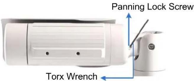
Figure 1-17
- Adjust the angle of camera body to the right or the left, and fasten the panning lock screw.
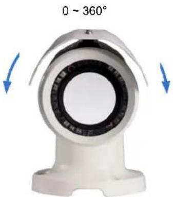
natural_image
Close-up of a white mechanical component with circular bore and central bore, showing directional arrows indicating rotation (no text or symbols)Figure 1-18
Second Shaft
You can adjust the camera body up and down by 90, 112.5, 135, 157.5 or 180 degrees by using the gears inside the camera body and the camera base.
- Unscrew the tilting lock screw with the torx wrench.
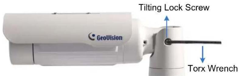
Figure 1-19
- Hold the camera body, and move the camera base to the right to separate the camera gears.
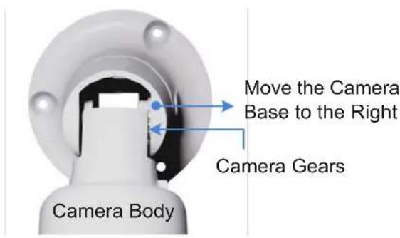
Figure 1-20
- Adjust the angle of camera body to 90^ , 112.5^ , 135^ , 157.5^ or 180^ . Then move the camera base to the left to combine the gears.
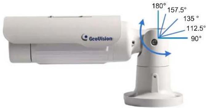
Figure 1-21
- Fasten the tilting lock screw.
Third Shaft
You can adjust the camera base by 360°.
- Unscrew the base fixing screw with the torx wrench.
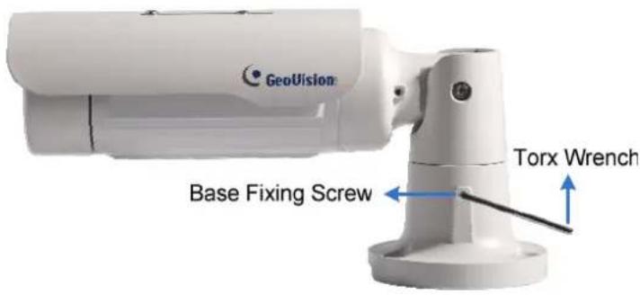
Figure 1-22
- Adjust the angle of camera base, and fasten the base fixing screw.
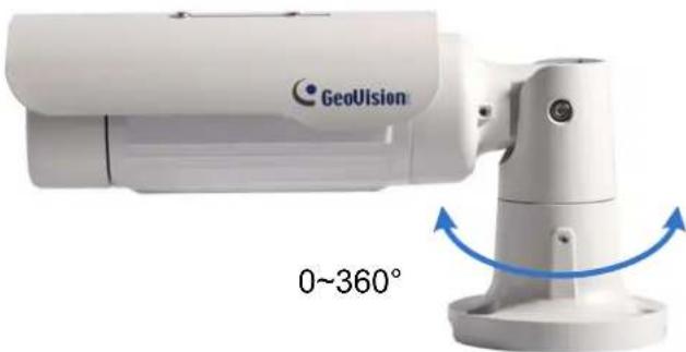
natural_image
Geovision camera module with angular measurement annotation (0~360°) shown, no readable text or symbols on device bodyFigure 1-23
1.2.8 Replacing the Silica Gel Bag
To replace the original silica gel bag with a new one, follow the steps below.
- Loosen the camera's cover.
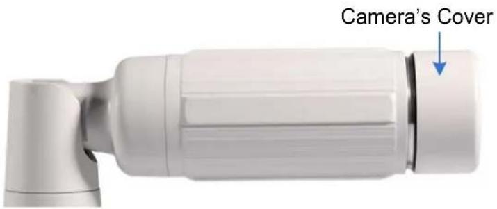
Figure 1-24
- Remove the silica gel bag.
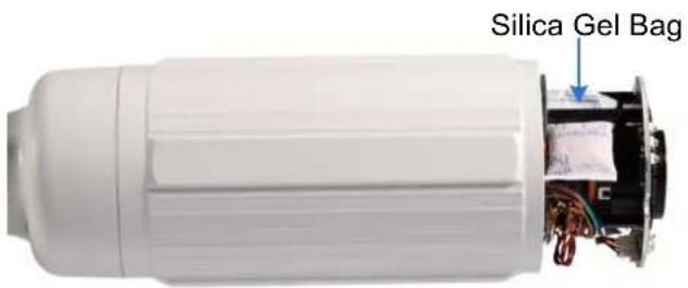
Figure 1-25
- Insert a new silica gel bag to the camera module and fasten the camera's cover within 2 minutes of opening the silica gel bag package.
IMPORTANT:
- The silica gel loses its effectiveness when the dry camera is opened. To prevent the lens from fogging up, replace the silica gel bag every time when you open the camera and conceal the gel bag in the camera within two minutes of exposing to the open air.
- For each newly replaced silica gel bag, allow it to absorb moisture for at least 5 hours before operating the camera.
1.2.9 Installing the Sun-Shield Cover
After setting up the Bullet Camera, now you can install the sun-shield cover to the camera.
- Fasten the hexagon screws either on top or below the camera.
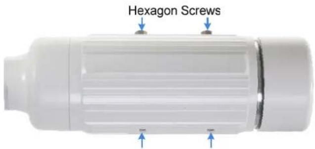
Figure 1-26
- Put the sun-shield cover on top of hexagon screws. Make sure to aim the rear hexagon screw at the edge of the sun-shield cover's aperture for optimal sun-shield performance.
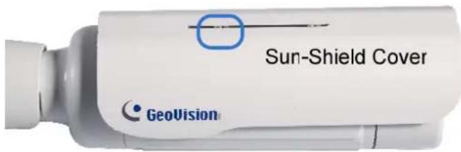
Figure 1-27
- Fasten the Philips head screws with the plastic screw spacers.
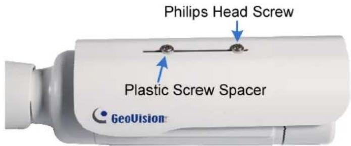
Figure 1-28
Chapter 2 Getting Started
2.1 Looking Up the IP Address
By default, your GV-Hybrid LPR Camera 20R / 10R / GV-IP LPR Camera 5R is assigned with an unused IP address by the DHCP server when the camera is connected to the network. This IP address remains unchanged unless you unplug or disconnect your camera from the network.
Note: If your router does not support DHCP, the default IP address will be 192.168.0.10. In this case, it is strongly suggested to modify the IP address to avoid IP address conflict with other GeoVision IP device on the same LAN. To change the IP address, see Changing the IP Address later in this section.
Follow the steps below to find out the IP address of your camera:
- Install the GV-IP Device Utility program from the Software DVD.
Note: The PC installed with GV-IP Device Utility must be under the same LAN with the camera you wish to configure.
- On the PC desktop, select Start, point to Programs and select GV IP Device Utility to execute the program. The GV-IP Device Utility window appears and automatically searches for the GV-IP devices on the same LAN.
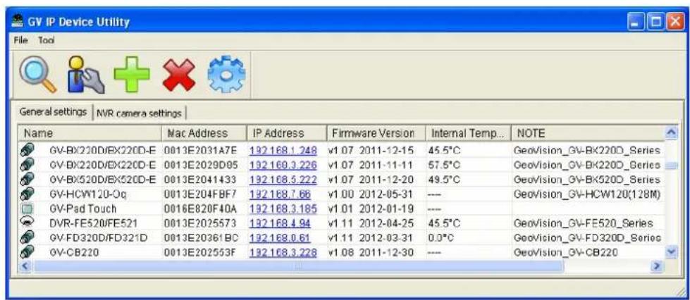
Figure 2-1
3. Click the Name or Mac Address column to sort.
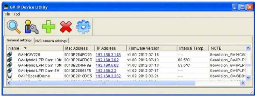
Figure 2-2
4. Find the Mac Address of the camera to see its IP address.
Changing the IP Address
To modify the static IP address or set the camera to a public dynamic IP address, log in the Web interface to access the network setting page.
- Open your Web browser, and type in the IP address.
• For static network connection, type the default IP address http://192.168.0.10
- For DHCP connection, follow steps in 2.1 Looking Up the IP Address to look up the current IP address.
-
In both Login and Password fields, type the default value admin. Click Apply.
-
In the left menu, select Network and then LAN to begin the network settings. This page appears.
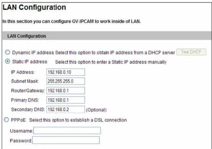
Figure 2-3
- Select Static IP address or PPPoE and type the required network information.
- Click Apply. The camera is now accessible by entering the assigned IP address on the Web browser.
Important:
- If your camera uses a public dynamic IP address via PPPoE, use the dynamic DNS Service to obtain a domain name linked to the camera's changing IP address first. For details on Dynamic IP Address and PPPoE, see 4.5.2 Advanced TCP/IP and 4.5.1 LAN Configuration.
- If PPPoE is enabled and you cannot access the camera, you may have to reset it to the factory default and then perform the network settings again. To restore the factory settings, see 5.3 Restoring to Factory Default Settings.
2.2 Accessing Your Surveillance Images
Follow these steps to access your surveillance images:
- Open the Internet Explorer browser.
- Enter the IP address or domain name of the GV-Hybrid LPR Camera 20R / 10R / GV-IP LPR Camera 5R in the Location/Address field of your browser. To look up the IP address, see 2.1 Looking Up the IP Address.
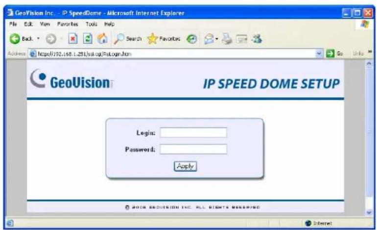
Figure 2-4
-
Enter the login name and password. The administrator account has unrestricted access to all the features and functions. The guest account is restricted to accessing live view and network status information.
-
The default login name and password for Administrator are admin.
• The default login name and password for Guest are guest. -
A video image, similar to the example in Figure 3-1, is now displayed on your browser.
Note: To enable the updating of images in Microsoft Internet Explorer, you must set your browser to allow ActiveX Controls and perform a once-only installation of GeoVision's ActiveX component onto your computer.
2.3 Configuring the Basics
Once you have installed and logged in the GV-Hybrid LPR Camera 20R / 10R / GV-IP LPR Camera 5R, you are ready to configure some of its primary settings through the Web interface:
• Date and time adjustment: see 4.6.1 Date and Time Settings.
- Login and privileged passwords: see 4.6.4 User Account.
• Network gateway: see 4.5 Network.
• Camera image adjustment: see 3.2 The Control Panel of the Live View Window.
• Video format, resolution and frame rate: see 4.1.1 Video Settings.
Chapter 3 Guest Mode and Live View Panel
This section introduces the features of the guest mode and the Live View window.
Main Page of Guest Mode
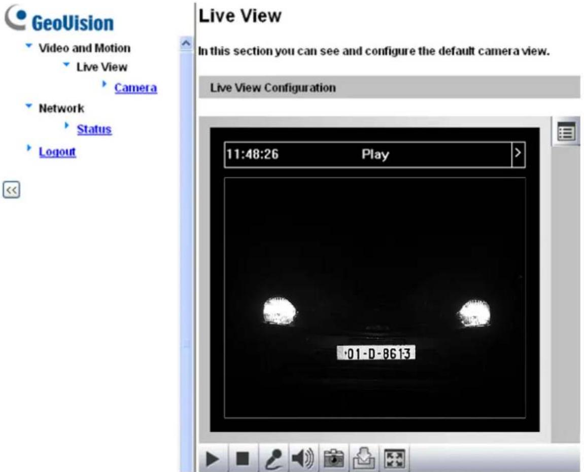
Figure 3-1
3.1 The Live View Window
In the left menu, click Live View, and then select Camera to see the live video.
Live View
In this section you can see and configure the default camera view.
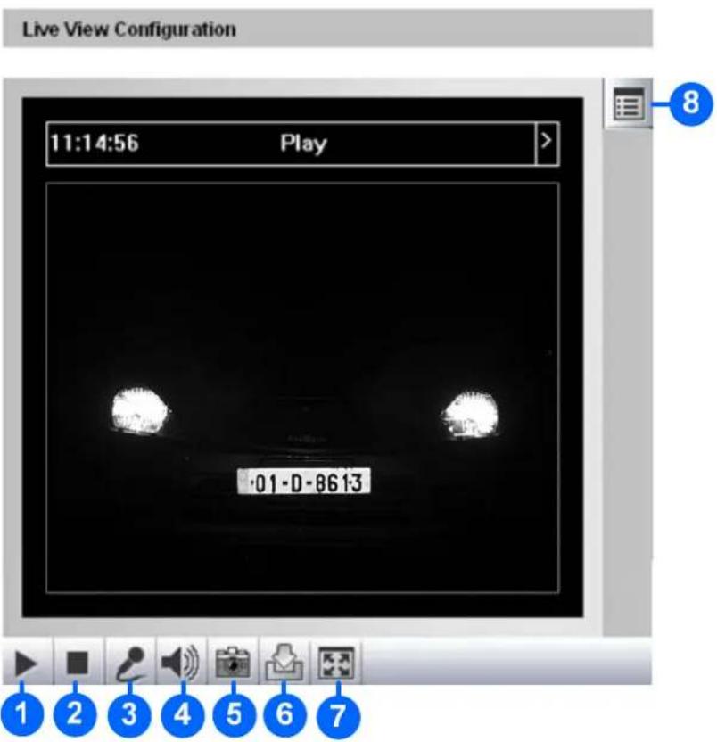
Figure 3-2
| No. | Name Function | |
| 1 | Play | Plays live video. |
| 2 Stop | Stops playing video. | |
| 3 | Microphone | Talks to the surveillance area from the local computer. Note this function is not available for GV-IP LPR Camera 5R. |
| 4 | Speaker | Listens to the audio around the camera. Note this function is not available for GV-IP LPR Camera 5R. |
| 5 | Snapshot | Takes a snapshot of live video.--- See 3.3 Snapshot of a Live Video. |
| 6 | File Save | Records live video to the local computer.--- See 3.4 Video Recording. |
| 7 | Full Screen | Switches to full screen view. Right-click the image to have these options:Snapshot, Full Screen, Resolution, PIP, PAP, GPS and Google Maps.--- See 3.5 Picture-in-Picture and Picture-and-Picture View. |
| 8 | Show System Menu | Brings up these functions: Alarm Notify, Video and Audio Configuration, Remote Config, Show Camera Name and Image Enhance.--- See 3.6 Alarm Notification, 3.7 Video and Audio Configuration, 3.8 Remote Configuration, 3.9 Camera Name Display and 3.10 Image Enhancement respectively. |
3.2 The Control Panel of the Live View Window
To open the control panel of the Live View window, click the arrow button on top of the viewer. You can access the following functions by using the right and left arrow buttons on the control panel.
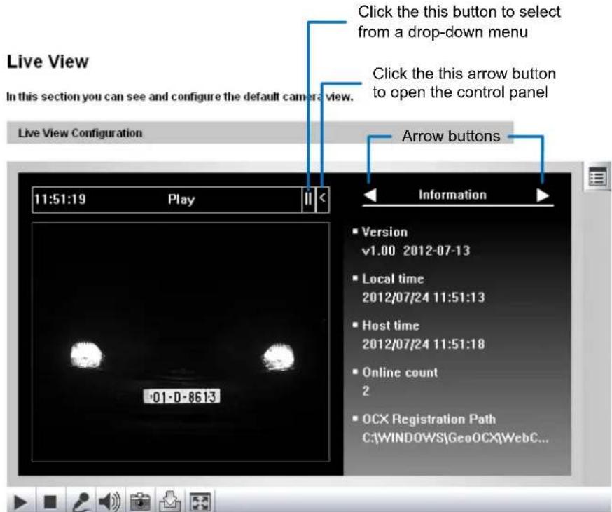
Figure 3-3
[Information] Displays the version of the GV-Hybrid LPR Camera 20R / 10R / GV-IP LPR Camera 5R, local time of the local computer, time of the camera, the number of users logging in to the camera and the OCX registration path.
[Video] Displays the current video codec, resolution and data rate.
[Audio] Displays the audio data rates when the microphone and speaker devices are enabled.
[Alarm Notify] Displays the captured images by motion detection. For this function to work, you must configure the Alarm Notify settings first. See 3.6 Alarm Notification.
[Camera Adjustment] Adjust the image quality settings. Click Save to store the changes to the settings.
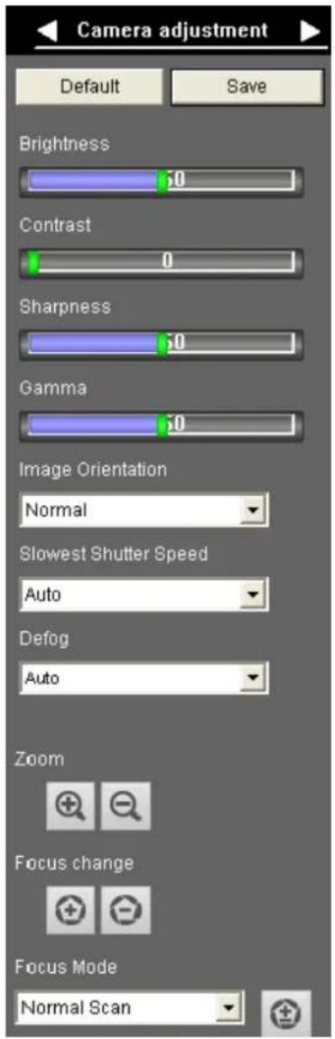
Figure 3-4
■ Brightness: Adjust the brightness of the image.
■ Contrast: Adjust the relative differences between one pixel and the next.
■ Sharpness: Adjust the sharpness of the image.
■ Gamma: Adjust the relative proportions of bright and dark areas.
■ Image Orientation: Change the image orientation on the Live View window.
■ Slowest Shutter Speed: Set the shutter speed. Shutter speed controls the amount of the lights enters the image sensor and directly impacts the quality of image presentation. A slow shutter speed allows higher light exposure that creates a brighter overall image by blurring moving objects and bringing out background details, and a faster shutter speed lowers color and image clarity in order to capture motions. The minimum shutter speed ranges from 1/500 to 1/8000 sec. Select Auto for automatic shutter control or select a shutter speed value.
■ Defog: Select Auto to automatically enhance the visibility of images. Select Close to disable the function.
■ Zoom: Click the Zoom In Ⓧ and Zoom Out Ⓧ buttons to adjust the apparent distance of the scene. Note this function is only available for GV-IP LPR Camera 5R.
■ Focus Change: Click the Focus In ⚙️ and Focus Out ⚙️ buttons to adjust the focus. To focus automatically, click the Auto Focus ⚙️ button. Note this function is only available for GV-IP LPR Camera 5R.
■ Focus Mode: Select Normal Scan, Regional Scan or Full Scan and then click the Start ⏻ button to automatically adjust the camera focus. The Normal Scan mode focuses the camera the fastest. The Regional Scan mode focuses the area selected on the live view. The Full Scan mode performs a detailed checkup and applies the best focus. Note this function is only available for GV-IP LPR Camera 5R.
[GPS] Position the GV-Hybrid LPR Camera 20R / 10R / GV-IP LPR Camera 5R on Google maps. For details, see 4.6.2 GPS Maps Settings.
[Internal Temperature] Shows the current internal temperature of the camera and the normal temperature range.
[Download] Allows you to install programs from the hard drive.
3.3 Snapshot of a Live Video
To take a snapshot of live video, follow these steps:
- Click the Snapshot button (No. 5, Figure 3-2). The Save As dialog box appears.
- Specify Save in, type the File name, and select JPEG or BMP for Save as Type. You may also choose to display the camera name and/or the date, the text color and image quality for the snapshot.
- Click the Save button to save the image in the local computer.
Note: You can also obtain a snapshot of the live view without logging in the user interface by executing the CGI command. See Appendix A.
3.4 Video Recording
You can record live video for a certain period of time to your local computer.
- Click the File Save button (No. 6, Figure 3-2). The Save As dialog box appears.
- Specify Save in, type the File name, and move the Time Period scroll bar to specify the time length of the video clip from 1 to 5 minutes.
- Click the Save button to start recording.
- To stop recording, click the Stop button (No. 2, Figure 3-2).
3.5 Picture-in-Picture and Picture-and-Picture View
The Live View window provides two types of close-up views: Picture-in-Picture (PIP) and Picture-and Picture (PAP). The two views are useful to provide clear and detailed images of the surveillance area.
Picture-in-Picture View
With the Picture-in-Picture (PIP) view, you can crop the video to get a close-up view or zoom in on the video.
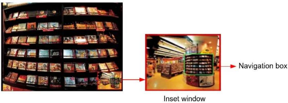
Figure 3-5
- Right-click the live view and select PIP. An inset window appears.
- Click the insert window. A navigation box appears.
- Move the navigation box around in the inset window to have a close-up view of the selected area.
- To adjust the navigation box size, move the cursor to any of the box corners, and enlarge or diminish the box.
- To exit the PIP view, right-click the image and click PIP again.
Picture-and-Picture View
With the Picture-and-Picture (PAP) view, you can create a split video effect with multiple close-up views on the image. A total of 7 close-up views can be defined.
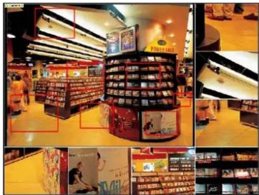
Figure 3-6
- Right-click the live view and select PAP. A row of three inset windows appears at the bottom.
- Draw a navigation box on the image, and this selected area is immediately reflected in one inset window. Up to seven navigation boxes can be drawn on the image.
- To adjust a navigation box size, move the cursor to any of the box corners, and enlarge or diminish the box.
-
To move a navigation box to another area on the image, drag it to that area.
-
To add, display/hide or to change the frame color of the navigation boxes, right-click the live view, select Mega Pixel Setting and click one of these options:
■ Enable Add-Focus-Area Mode: Allows the user to add navigation boxes to the image.
■ Display Focus Area of PAP Mode: Displays or hides the navigation boxes on the image
■ Set Color of Focus Area: Changes the color of the box frames.
-
To delete a navigation box, right-click the desired box, select Focus Area of PAP Mode and click Delete.
-
To exit the PAP view, right-click the image and click PAP again.
3.6 Alarm Notification
When a motion is detected, you can be alerted by a pop-up live video and view up to four captured images.
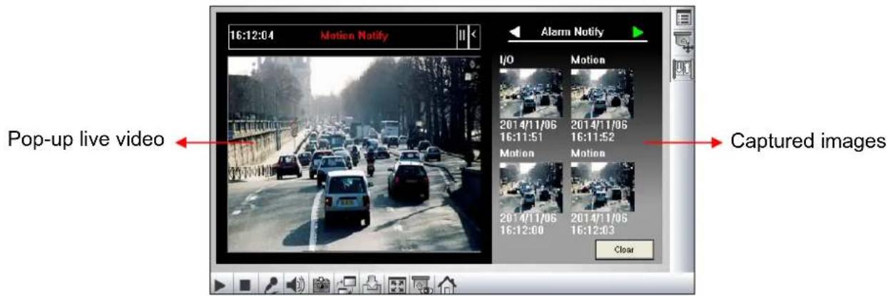
Figure 3-7
To configure this function, click the Show System Menu button (No. 8, Figure 3-2), and select Alarm Notify. This dialog box appears.
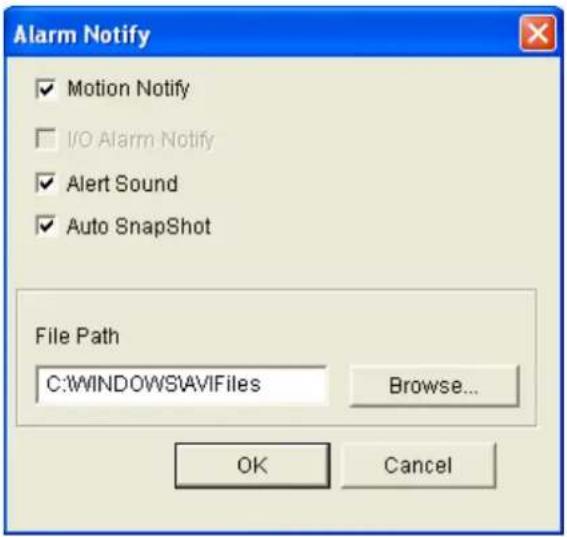
Figure 3-8
■ Motion Notify: Once motion is detected, the captured images are displayed on the control panel of the Live View window.
■ I/O Alarm Notify: This function is not available for GV-Hybrid LPR Camera 20R / 10R / GV-IP LPR Camera 5R.
■ Alert Sound: Activates the computer alarm on motion.
■ Auto Snapshot: The snapshot of live video is taken every 5 seconds on motion.
■ File Path: Assigns a file path to save the snapshots.
3.7 Video and Audio Configuration
You can enable the microphone and speaker for two-way audio communication and adjust the set the number of frames to keep for live view buffer.
Click the Show System Menu button (No. 8, Figure 3-2), and select Video and Audio Configuration.
■ Camera: Sets the number of frames to keep in live view buffer. Keeping more frames for live view buffer can ensure a smooth live view, but the live view will be delayed for the number of seconds specified.
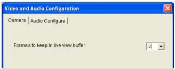
Figure 3-9
■ Audio Configure: You can enable the microphone and speaker and adjust the audio volume. Note this setting is not available for GV-IP LPR Camera 5R.
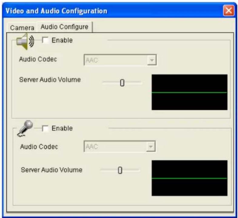
Figure 3-10
3.8 Remote Configuration
You can upgrade the device firmware over the network. Click the Show System Menu button (No. 8, Figure 3-2), and select Remote Config. The Remote Config dialog box will appear.
[Firmware Upgrade] In this tab, you can upgrade the firmware over the network. For details, see Chapter 5 Advanced Applications.
3.9 Camera Name Display
To display the camera name on the image, click the Show System Menu button (No. 8, Figure 3-2), and select Show Camera Name.
3.10 Image Enhancement
To enhance the image quality of live video, click the Show System Menu button (No. 8, Figure 3-2), and select Image Enhance. This dialog box appears.
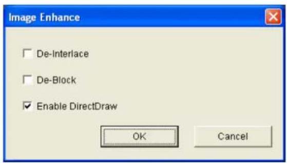
Figure 3-11
■ De-Interlace: Covert the interlaced video into non-interlaced video.
■ De-Block: Remove the block-like artifacts from low-quality and highly compressed video.
■ Enable DirectDraw: Activate the DirectDraw function.
Chapter 4 Administrator Mode
The Administrator can access and configure the GV-Hybrid LPR Camera 20R / 10R / GV-IP LPR Camera 5R over the network. The configuration categories include: Video and Motion, Events and Alerts, Monitoring, Recording Schedule, Remote ViewLog, Network, and Management.
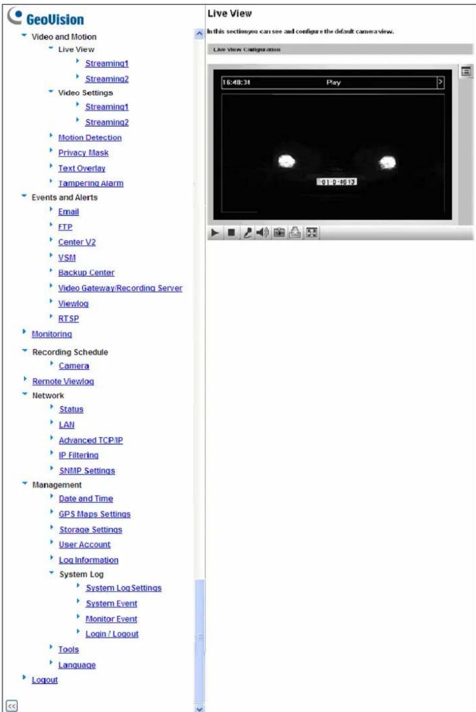
Figure 4-1
Corresponding Section for Configuration Menu
Find the topic of interest by referring to the indicated section.
| 4.1 Video and Motion | 4.1.1 Video Settings4.1.2 Motion Detection4.1.3 Privacy Mask4.1.4 Text Overlay4.1.5 Tampering Alarm |
| 4.2 Events and Alerts | 4.2.1 Email4.2.2 FTP4.2.3 Center V24.2.4 VSM4.2.5 Backup Center4.2.6 GV-Video Gateway / GV-Recording Server4.2.7 ViewLog4.2.8 RTSP |
| 4.3 Monitoring | 4.3.1 GV-Hybrid LPR Camera 20R / 10R4.3.2 GV-IP LPR Camera 5R |
| 4.4 Recording Schedule 4.4.1 | Recording Schedule Settings |
| 4.5 Network | 4.5.1 LAN4.5.2 Advanced TCP/IP4.5.3 IP Filter4.5.4 SNMP Settings |
| 4.6 Management | 4.6.1 Date and Time Settings4.6.2 GPS Maps Settings4.6.3 Storage Settings4.6.4 User Account4.6.5 Log Information4.6.6 System Log4.6.7 Tools4.6.8 Language |
4.1 Video & Motion
The GV-Hybrid LPR Camera 20R / 10R / GV-IP LPR Camera 5R supports dual streams, Streaming 1 and Streaming 2, which allow separate codec and resolutions settings for a single video transmission. In a bandwidth-limited network, such as mobile phone surveillance, this dual-stream feature allows you to view live video in lower resolution and codec (Streaming 2), and record in highest resolution 1280 x 1024 and codec MJPEG (Streaming 1) at the same time.
Comparison between Stream 1 and Stream 2:
| Video Setting Options | Stream 1 Stream 2 | |
| Video Signal Type | Different codec, resolutions and frame rates can be applied to Stream 1 and 2. | |
| Watermark Setting | Yes | Not configurable. Settings in Stream 1 will be automatically applied to Stream 2. |
| Audio Codec | ||
| TV Out Setting | ||
| Status LED Control | ||
4.1.1 Video Settings
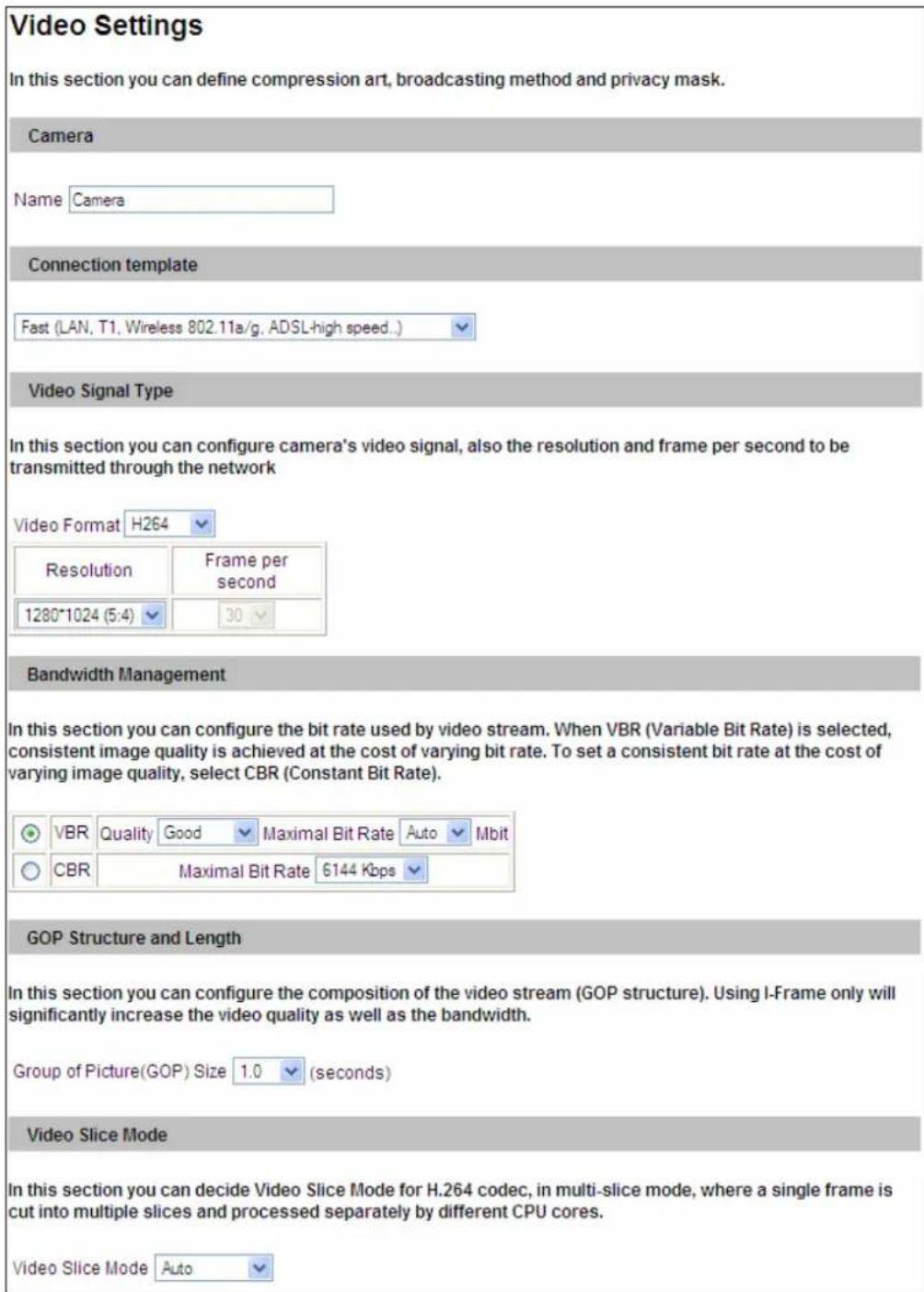
Figure 4-2A
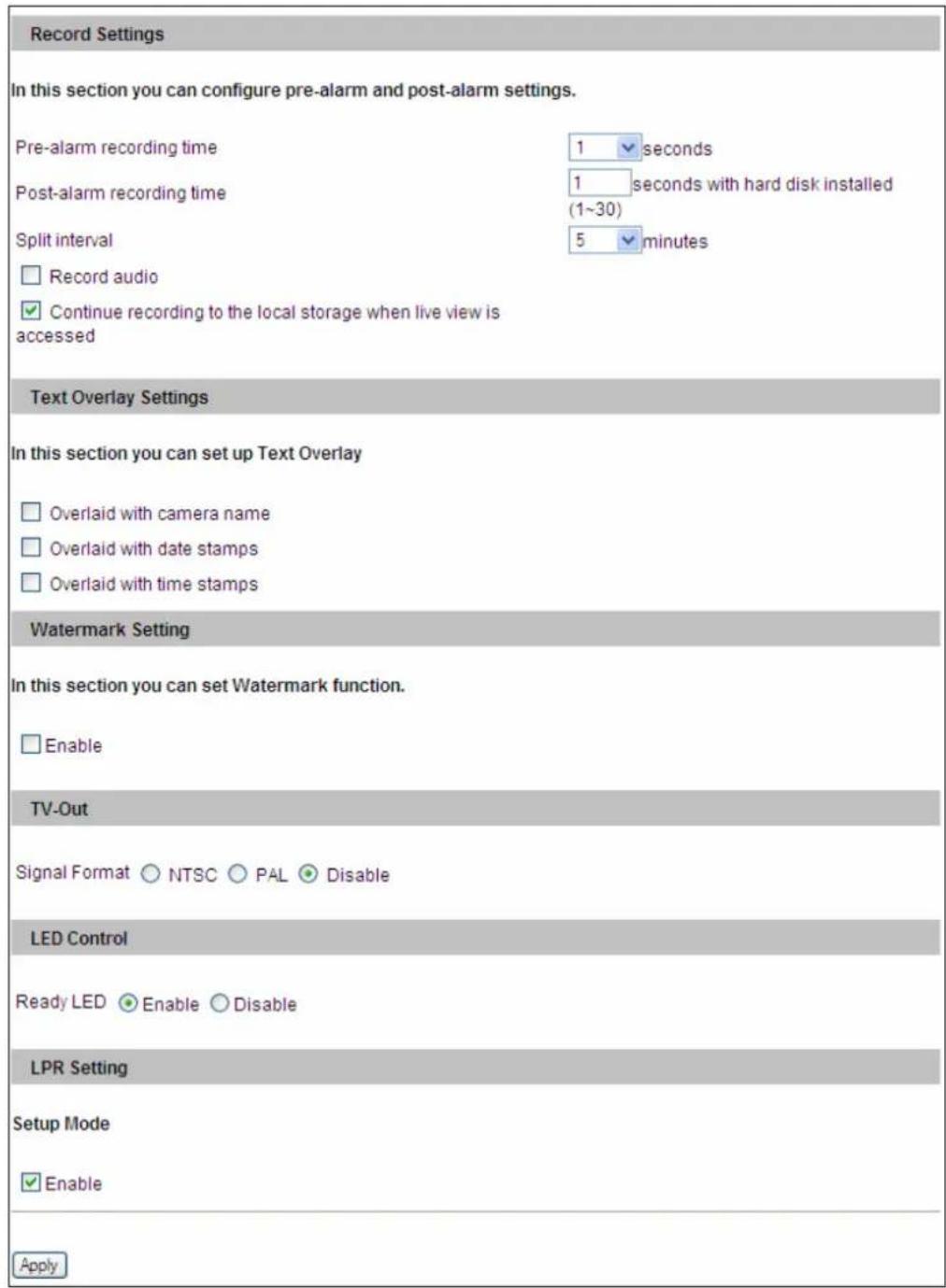
Figure 4-2B
[Name]
Rename the camera. The camera name will appear on the Live View. To display the camera name, see 3.9 Camera Name Display.
[Connection Template]
Select the type of your network connection. Unless you select Customized, this option will automatically bring up the recommended video resolution, frame rate, bandwidth and GOP size.
[Video Signal Type]
Select the codec type, resolution and frame rate. The default codec is MJPEG. Choose H.264 or MJPEG for the main stream/sub stream. The supported resolutions are listed blow:
| Video Resolution | ||
| Main Stream | 4:3 | 1280 x 960, 640 x 480, 320 x 240 |
| 16.9 | 1280 x 720, 640 x 360, 448 x 252 | |
| 5:4 | 1280 x 1024, 640 x 512, 320 x 256 | |
| Sub Stream | 4:3 | 640 x 480, 320 x 240 |
| 16.9 | 640 x 360, 448 x 252 | |
| 5:4 | 640 x 512, 320 x 256 | |
[Bandwidth Management]
When using the H.264 codec, it is possible to configure the bitrate settings to control bandwidth usage.
■ VBR (Variable Bitrate): The quality of the video stream is kept as constant as possible at the cost of a varying bitrate. The bandwidth is much more efficiently used than a comparable CBR. Set the image quality to one of the 5 standards: Standard, Fair, Good, Great and Excellent.
Maximal Bit Rate: When the system bitrate exceeds the specified Maximal Bit Rate, the system will automatically lower its bitrate so as not to exceed it. Select one of the bitrates from the drop-down list or select Auto if you do not want to enable this function. The default value is 6 MB
■ CBR (Constant Bitrate): CBR is used to achieve a specific bitrate by varying the quality of the stream. The bitrates available for selection depend on the image resolution.
[GOP Structure and Length]
Set the maximum number of seconds between every key frame.
[Video Slice Mode]
Select Single Slice if the camera is displayed on a third-party NVR/DVR software and the live view is incomplete or broken. The default is Auto.
[Record Settings]
Note this function is not available for GV-Hybrid LPR Camera 20R / 10R. The alarm settings allow you to capture images before and/or after the motion happens.
■ Pre-alarm recording time: Activate video recording before an event occurs. Set the recording time to 1 or 2 seconds. The recording is saved in the buffer of the camera.
■ Post-alarm recording time: Activate video recording onto the inserted memory card after an event occurs. Set the recording time from 1 to 30 seconds.
■ Split interval: Set the maximum time length of each recorded file from 1 to 5 minutes.
■ Continue recording to the local storage when live view is accessed: Select this function for continuous recording to the memory card even when the live view is accessed through the Web interface or other software. This option is enabled by default.
[Text Overlay Settings]
■ Overlaid with camera name: Include camera names on live and recorded videos.
■ Overlaid with date stamps: Include date stamps on live and recorded videos.
■ Overlaid with time stamps: Include time stamps on live and recorded videos.
[Watermark Setting]
Enable this option to watermark all recordings. The watermark allows you to verify whether the video has been tampered while it was recorded. See 5.4 Verifying Watermark.
[TV Out]
Select the signal format for the video output of the camera as either NTSC or PAL. This function is disabled by default. Note this function is not available for GV-IP LPR Camera 5R.
[LED Control]
■ Ready LED: Select Disable if you do not wish to use the Status LED. Note this function is not available for GV-IP LPR Camera 5R.
[LPR Setting]
- Setup Mode: Select Enable to keep the brightness of the live view when the camera's cover is removed for focus adjustment. This function can prevent the live view from being darkened when the camera's cover with infrared illuminator is uninstalled. Note this function is not available for GV-IP LPR Camera 5R.
Note: When this function is enabled, the text of "Setup Mode" will be overlaid on the live view.
4.1.2 Motion Detection
Motion detection is used to generate an alarm whenever movement occurs within the scene. You can configure up to 8 detection zones with different sensitivity values. Create at least one detection zone to enable this function.
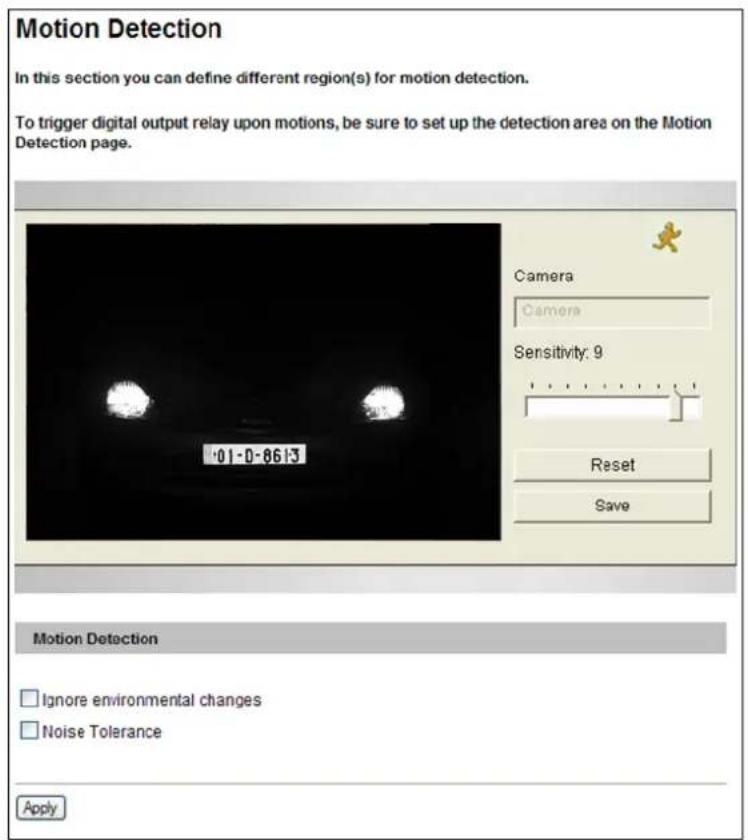
Figure 4-3
- Select a sensitivity value using the slider bar. There are 10 sensitivity levels. The higher the value, the more sensitive the camera is to motion. The default sensitivity value is 9.
- Define a detection zone by dragging an area on the image. Click Add when you are prompted to confirm the setting.
- To create several areas with different sensitivity values, repeat Steps 1 and 2.
- Click Save to save the above settings.
- Click Reset to clear all the selected areas.
- For the camera to ignore environmental changes such as rain or snow, select the Ignore environmental changes.
- To reduce video noise when the lighting condition changes, select Noise Tolerance.
- Click the Apply button.
4.1.3 Privacy Mask
The Privacy Mask can block out sensitive areas from view, covering the areas with dark boxes in both live view and recorded clips. This feature is ideal for privacy protection on locations with private information, keyboard sequences (e.g. passwords), and any place you would like to keep inaccessible to view.
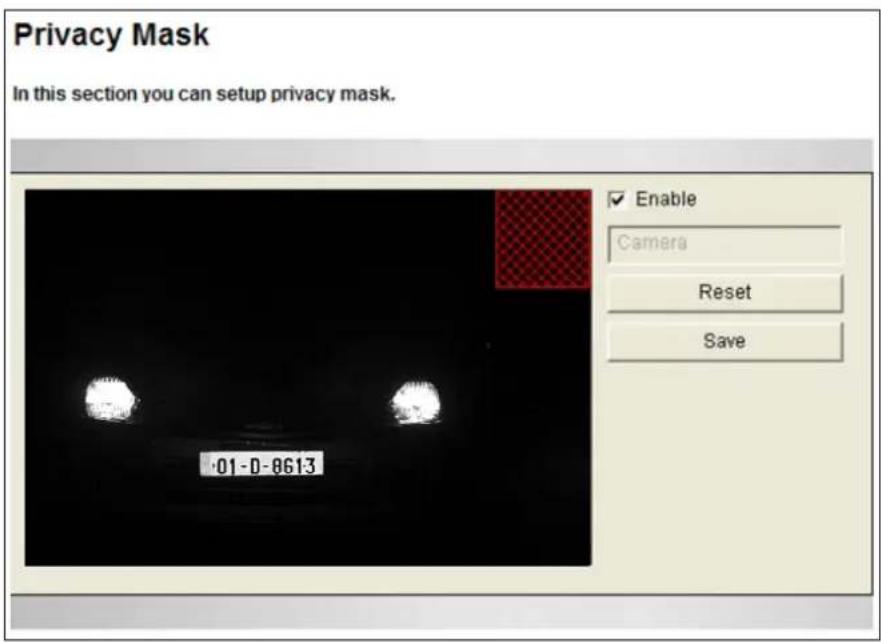
Figure 4-4
- Select the Enable option.
- Drag the area(s) where you want to block out on the image. Click Add when you are prompted to confirm the setting.
- Click the Save button to save all the settings.
4.1.4 Text Overlay
The Text Overlay allows you to overlay any text in any place on the camera view. Up to 16 text messages can be created on one camera view. The overlaid text will be saved in the recordings.
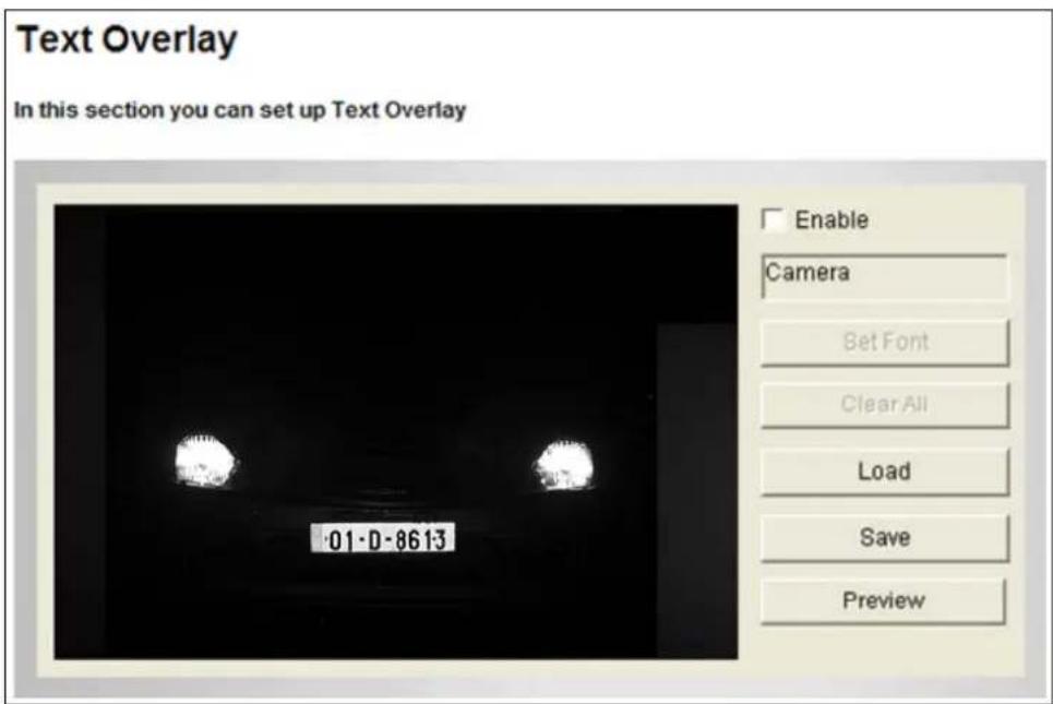
Figure 4-5
- Select the Enable option.
- Click Set Font to set up the font, font style and font size in a pop-up window.
- Click any place on the image. This dialog box appears.
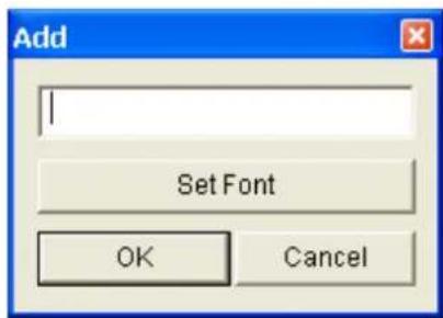
Figure 4-6
- Type the desired text, and click OK. The text is overlaid on the image.
- Drag the overlaid text to a desired place on the image.
- Click Set Font to modify the font settings.
- Click Save to apply the settings, or click Load (Undo) to revert to the last saved setting.
- Click Preview to see how the text will appear on the image. Click Close to end the preview.
4.1.5 Tampering Alarm
Note this function is not available for GV-IP LPR Camera 5R.
The Tampering Alarm is used to detect whether a camera is being physically tampered. An e-mail alarm can be sent when the camera is moved, covered up, or out of focus. Make sure the e-mail settings are set up. For detail, see 4.2.1 E-Mail.
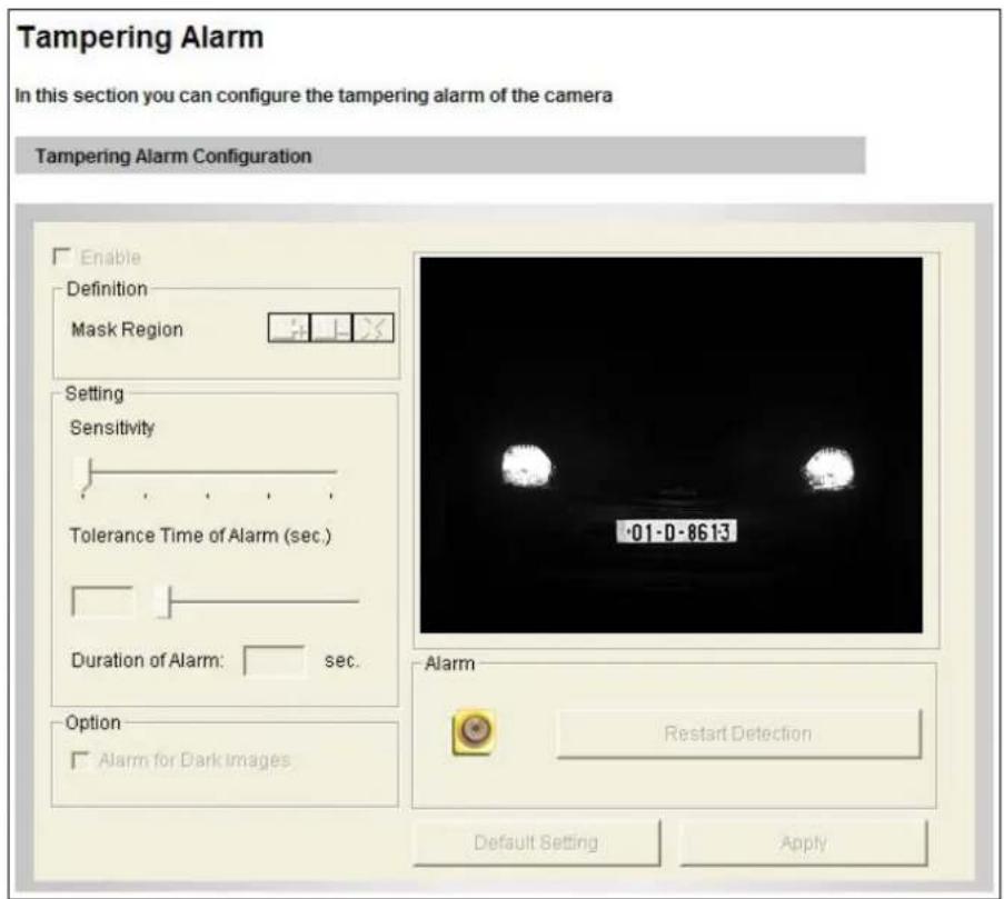
Figure 4-7
To configure the tampering alarm:
- Select the Enable option.
- If you want the camera to ignore any movement or scene change in certain areas, click the ☐ button to drag areas on the camera view.
- Select the desired detection sensitivity by moving the slider. The higher the value, the more sensitive the camera is to scene changes.
-
In the Tolerance Time of Alarm field, specify the time length allowed for scene changes before an e-mail notification is sent.
-
To trigger an alarm when the scene turns dark, e.g. the lens of camera has been covered, select Alarm for Dark Images.
- Click Apply to save all the settings.
4.2 Events & Alerts
For motion and tampering events, the Administrator can set up two types of alert:
- Send a captured image by e-mail or FTP. See 4.2.1 E-Mail and 4.2.2 FTP.
- Notify Center Monitoring Stations such as Center V2, VSM, by video or text alerts.
To enable above alerts, you must also set the following features:
• Motion Detection (See 3.1.2 Motion Detection)
- For e-mail and FTP alerts, it is required to start monitoring (See 4.3 Monitoring).
4.2.1 E-mail
When a motion is detected, the GV-Hybrid LPR Camera 20R / 10R / GV-IP LPR Camera 5R can send an e-mail alert, containing a captured image to a remote user.
Important: To send e-mail alert upon motion / tampering events, make sure you also enable the Motion Detection / Tampering Alarm function. For setup details, see 3.1.2 Motion Detection and 3.1.5 Tampering Alarm.
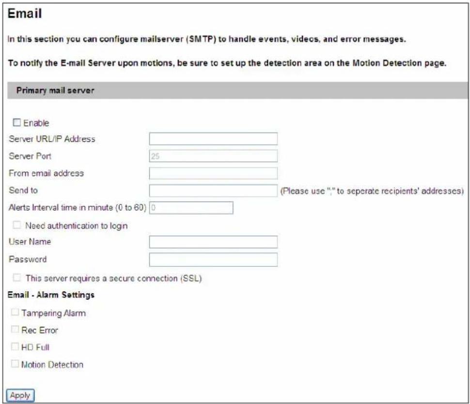
Figure 4-8
To enable the e-mail functions:
- Select Enable to set up e-mail notifications.
- Server URL/IP Address: Type the SMTP Server's URL address or IP address.
- Server Port: Type the SMTP Server's port number or keep the default value 25.
- From email address: Type the sender's e-mail address.
-
Send to: Type the e-mail address(s) you want to send alerts to.
-
Alerts interval time in minute: Specify the interval between e-mail alerts. The valid interval is from 0 to 60 minutes. This option is useful for frequent event occurrence. Any event detected during the interval period will be ignored.
- If the SMTP Server needs authentication, select Need authentication to login and type a valid Username and Password to log in the SMTP server. If the SMTP Server needs a secure connection (SSL), select This server requires a secure connection.
- Email-Alarm Settings: Select the event to automatically send an e-mail alert. Note the Tampering Alarm option is not available for GV-IP LPR Camera 5R.
- Click Apply.
- In the left menu, select Monitoring and click the Start button to start monitoring.
4.2.2 FTP
You can also send the captured image to a remote FTP server for alerts.
Important: To send FTP alert upon motions, be sure to set up the detection area on the Motion Detection page. For details, see 4.1.2 Motion Detection.
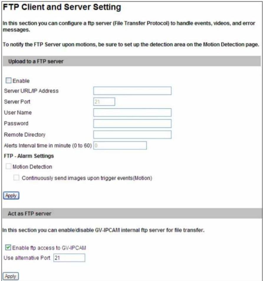
Figure 4-9
[Upload to a FTP server]
- Select Enable to set up the FTP function.
- Server URL/IP Address: Type the URL address or IP address of the FTP Server.
- Server Port: Type the port number of the FTP Server or keep the default value 21.
- Type the Username and Password of the FTP Server.
-
Remote Directory: Type the name of the storage folder on the FTP Server.
-
Alerts interval time in minute: Specify the interval between FTP alerts. The interval can be between 0 and 60 minutes. The option is useful for frequent event occurrence. Any event triggers during the interval period will be ignored.
- FTP-Alarm Settings: Select Motion Detection to automatically send a snapshot to the FTP Server upon motion detection. Select Continuously send images upon trigger events (Motion) to upload a series of snapshots to the FTP Server upon motion detection.
- In the left menu, select Monitoring and click the Start button to start monitoring.
[Act as FTP server]
- Enable FTP access to the GV-IP Cam: Select to allow the camera to act as an FTP server for users to download AVI files.
- Use alternative port: The default port is set to 21.
4.2.3 Center V2
The central monitoring station Center V2 can be notified of a motion event by live videos and text alerts. Up to two Center V2 servers can be connected. For live monitoring through Center V2, you must already have a subscriber account on each of the Center V2 server.
Important: To notify the Center V2 Server upon motion events, be sure to set up the detection area on the Motion Detection page. For details, see 4.1.2 Motion Detection and 7.1 Center V2.
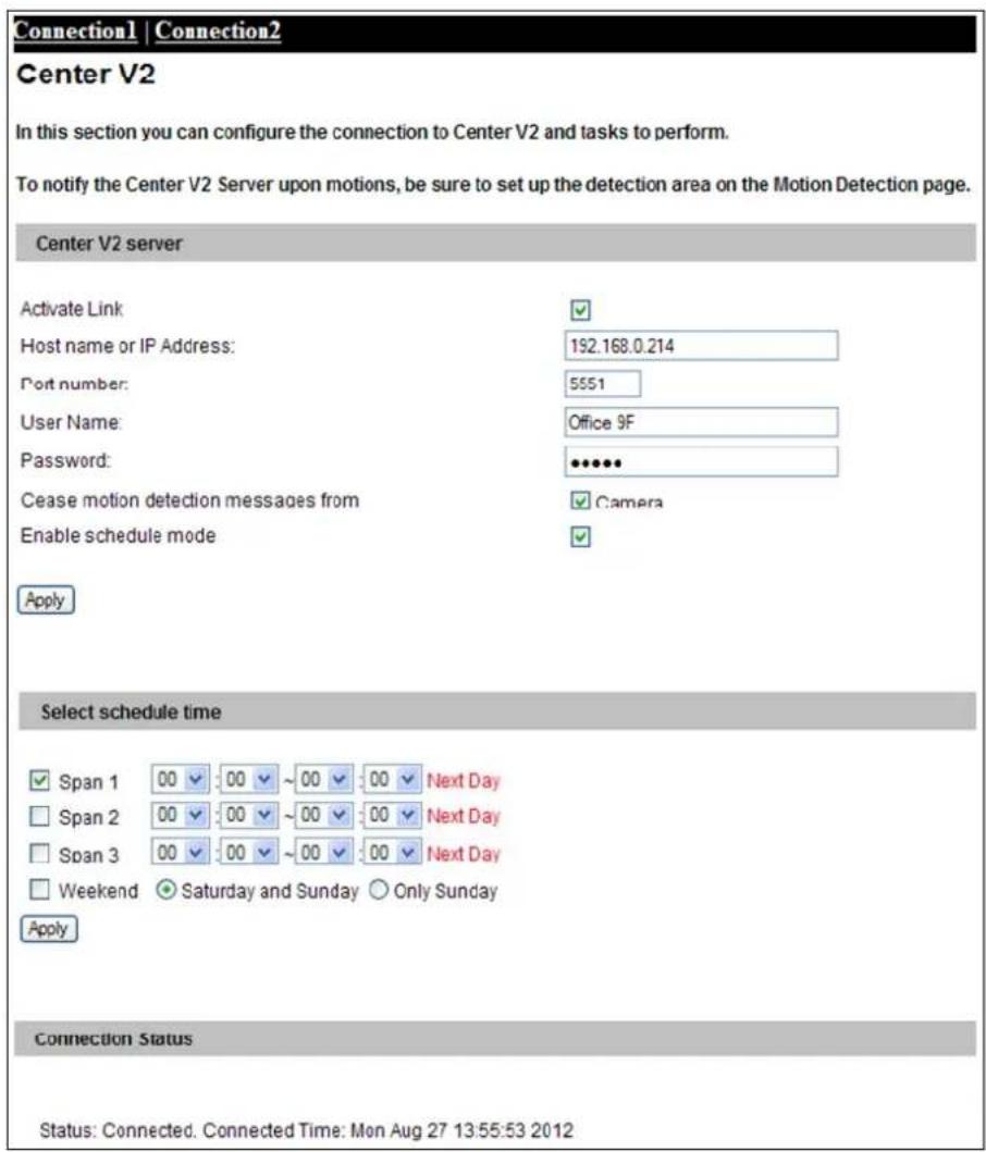
Figure 4-10
To enable the Center V2 connection:
- Activate Link: Enable the monitoring through Center V2.
- Host Name or IP Address: Type the host name or IP address of Center V2.
- Port Number: Match the port to Port 2 on Center V2. Or keep the default value 5551. For details, see 8.1 Center V2.
- User Name: Type a valid user name to log in to Center V2.
- Password: Type a valid password to log in to Center V2.
- Click Apply. The Connection Status should display "Connected" and connected time.
- To establish connection to the second Center V2, click the Connection 2 tab and repeat the above steps for setup.
You can also find on this Center V2 settings page:
■ Cease motion detection messages from: Stops notifying Center V2 of motion detection.
■ Enable schedule mode: Starts the monitoring through Center V2 based on the schedule you set in the Select Schedule Time section.
[Select schedule time]
■ Span 1- Span 3: Enable recording (upon motion events) at up to 3 different time frames for a day, represented by Span 1 to Span 3.
■ Weekend: Enable recording (upon motion events) for both Saturday and Sunday or for Sunday only.
4.2.4 VSM
The central monitoring station VSM can be notified of a motion event by text alerts. Up to two VSM servers can be connected. For live monitoring through VSM, you must already have a subscriber account on each of the VSM server.
Important: To notify the VSM upon motions, be sure to set up the detection area on the Motion Detection page. For details, see 4.1.2 Motion Detection and 7.2 VSM.
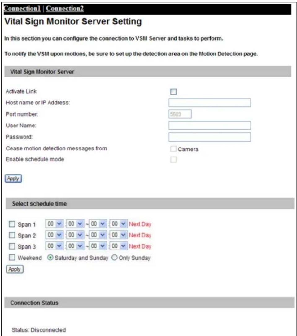
Figure 4-11
To enable the VSM connection:
- Activate Link: Enable the monitoring through VSM.
- Host Name or IP Address: Type the host name or IP address of VSM.
- Port Number: Match the port to Port 2 on VSM or keep the default value 5609. For details, see 7.2 VSM.
- User Name: Type a valid user name to log into VSM.
- Password: Type a valid password to log into VSM.
- Click Apply. The Connection Status should display "Connected" and connected time.
- To establish connection to the second VSM, click the Connection 2 tab and repeat the above steps for setup.
These options you can also find on this VSM setting page:
■ Cease motion detection messages from: Stops notifying VSM of motion detection.
■ Enable schedule mode: Starts the monitoring through VSM based on the schedule you set in the Select Schedule Time section. For schedule setup, refer to 4.2.3 Center V2.
4.2.5 Backup Center
Note this function is not available for GV-Hybrid LPR Camera 20R / 10R.
The connection to the GV-Backup Center allows you to back up another copy of recordings and system log to the GV-Backup Center on an offsite location while the camera is saving these data to the memory card. The GV-Backup Center provides a PC-based storage and backup solution. For details on the GV-Backup Center, see GV-Backup Center User's Manual.
Important: This function is currently not supported in GV-IP LPR Camera 5R.
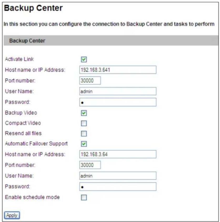
Figure 4-12
To enable connection to GV-Backup Center:
- Activate Link: Enable the connection to the GV-Backup Center.
-
Host Name or IP Address: Type the host name or IP address of the GV-Backup Center.
-
Port Number: Match the communication port on the GV-Backup Center or keep the default value 30000.
- User Name: Type a valid user name to log into the GV-Backup Center.
- Password: Type a valid password to log into the GV-Backup Center.
- Backup Video: Select the streams to back up their recordings to the GV-Backup Center.
- Compact Video: Select the streams to only back up their Key Frames to the GV-Backup Center, instead of full recordings. This option is useful to save the backup time.
- Resend all files: Select this option to send all the recorded files that have received by the Backup Center again.
- Enable Schedule Mode: Enable the GV-Backup Center connection on the schedule you set in the Select Schedule Time section. Refer to 4.4 Recording Schedule for the same settings.
- Click Apply. The Connection Status should display "Connected" and connected time.
If you have a failover GV-Backup Center server which provides uninterrupted backup services in case the first GV-Backup Center failed, configure the failover GV-Backup Center as below.
- Automatic Failover Support: Enable the automatic connection to the failover GV-Backup Center once the connection between camera and the first GV-Backup Center is interrupted.
- Host Name or IP Address: Type the host name or IP address of the failover GV-Backup Center.
- Port Number: Match the communication port on the failover GV-Backup Center or keep the default value 30000.
- User Name: Type a valid user name to log into the failover GV-Backup Center.
- Password: Type a valid password to log into the failover GV-Backup Center.
- Click Apply.
4.2.6 GV-Video Gateway / GV-Recording Server
The GV-Video Gateway and GV-Recording Server are video streaming servers designed for large-scale video surveillance deployments. The GV-Video Gateway / GV-Recording Server (with recording capability) can receive up to 128 channels from various IP video devices, and distribute up to 300 channels to its clients. With the GV-Video Gateway / GV-Recording Server, the desired frame rate can be ensured while the CPU loading and bandwidth usage of the IP video devices are significantly reduced.
The GV-Hybrid LPR Camera 20R / 10R / GV-IP LPR Camera 5R can be connected with up to two GV-Video Gateway / GV-Recording Server. To send the video images to the GV-Video Gateway or GV-Recording Server, you must already have an account on each of the GV-Video Gateway / GV-Recording Server with the user name and password specified below.
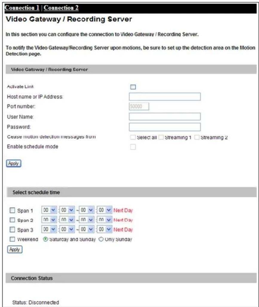
Figure 4-13
To enable connection to GV-Video Gateway / GV-Recording Server:
- Activate Link: Enable the monitoring through GV-Video Gateway / GV-Recording Server.
- Host Name or IP Address: Type the host name or IP address of the GV-Video Gateway / GV-Recording Server.
- Port Number: Match the communication port specified on GV-Video Gateway / GV-Recording Server. Or keep the default value 50000.
- User Name: Type a valid user name to log into GV-Video Gateway / GV-Recording Server.
- Password: Type a valid password to log into GV-Video Gateway / GV-Recording Server.
- Click Apply. The Connection Status should display "Connected" and connected time.
- To establish connection to the second GV-Video Gateway / GV-Recording Server, click the Connection 2 tab and repeat the above steps for setup.
You can also find these options:
■ Enable schedule mode: Starts the monitoring through GV-Video Gateway / GV-Recording Server based on the schedule you set in the Select Schedule Time section. For schedule setup, refer to 4.2.3 Center V2.
■ Cease motion detection messages from: Stops notifying GV-Video Gateway / GV-Recording Server of motion events.
4.2.7 ViewLog
Note this function is not available for GV-Hybrid LPR Camera 20R / 10R.
The ViewLog Server is designed for remote playback function. This server allows you to remotely access the recorded files saved at the camera and play back video with the ViewLog player.
This function is enabled by default using port 5552. Keep the default setting and only modify it when necessary.
Important: This function is currently not supported in GV-IP LPR Camera 5R.
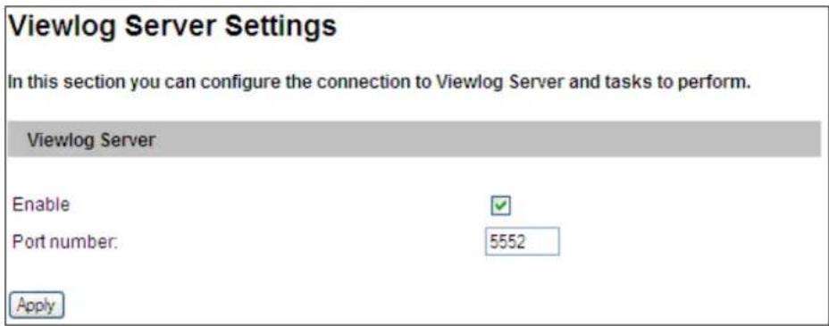
Figure 4-14
4.2.8 RTSP
The RTSP Server enables video and audio streaming to your 3G-enabled mobile phone.
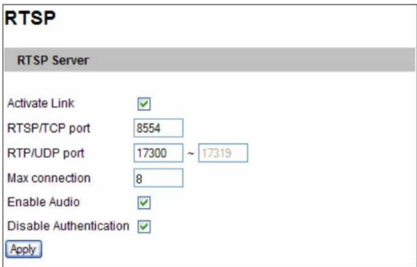
Figure 4-15
■ Activate Link: Enable the RTSP / 3GPP service.
■ RTSP/TCP Port: Keep the default value 8554, or modify it if necessary.
■ RTP/UDP Port: Keep the default range from 17300 to 17319, or modify it if necessary. The number of ports for use is limited to 20.
■ Max Connection: Set the maximum number of RTSP and 3GPP connections to the GV-Hybrid LPR Camera 20R / 10R / GV-IP LPR Camera 5R. The maximum value is 8.
■ Enable Audio: This option is enabled by default. Select to enable audio streaming through RTSP. Note this function is not available for GV-IP LPR Camera 5R.
■ Disable Authentication: Authentication is disabled by default, with which the ID and password of the GV-Hybrid LPR Camera 20R / 10R / GV-IP LPR Camera 5R are not required when accessing live view through the RTSP command.
For details on remote monitoring with mobile phones, see Smart Device Connection, Chapter 8. For RTSP command, see Appendix B RTSP Protocol Support.
4.3 Monitoring
Configure the monitoring settings for GV-Hybrid LPR Camera 20R / 10R / GV-IP LPR Camera 5R.
4.3.1 GV-Hybrid LPR Camera 20R / 10R
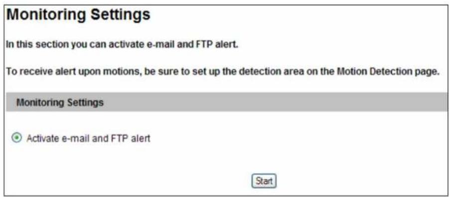
Figure 4-16
[Activate e-mail and FTP alert] Allows the camera to send e-mail and/or FTP alert upon motion events. Select this option and click the Start button.
4.3.2 GV-IP LPR Camera 5R
You can start monitoring manually or by schedule.
Important: This function is currently not supported in GV-IP LPR Camera 5R.
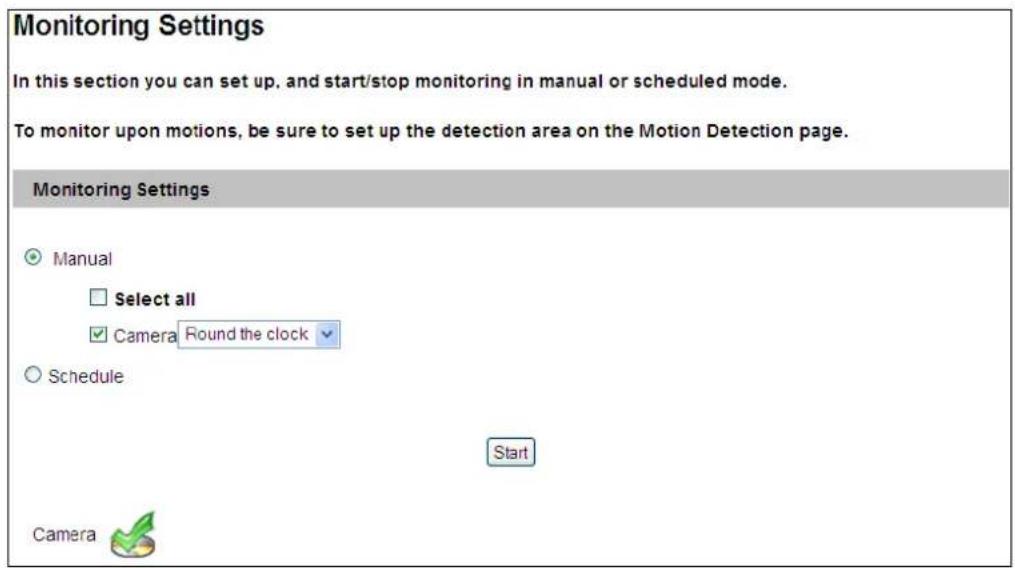
Figure 4-16
[Manual] Manually activates motion detection. Select one of the following options and click the Start button.
■ Select all: Manually starts motion detection.
■ Camera: Manually starts recording. Select the desired recording mode for recording.
[Schedule] The system starts motion detection according to the schedule you have set. For schedule settings, see 4.4 Recording Schedule.
[Camera Status Icon]
![Geovision GV-HYBRIDLPR - [Camera Status Icon] - 1](/content/2026/06/1146107/images/6c14786eac562f82feae49506d23aada11bec3da5ac590fbe76c0d5259311a6c.jpg)
: On standby
![Geovision GV-HYBRIDLPR - [Camera Status Icon] - 2](/content/2026/06/1146107/images/790d524332eb1026c0cfa500b364859611e6f4b65c930403c409831ee0b4484b.jpg)
: Enabled for motion detection
![Geovision GV-HYBRIDLPR - [Camera Status Icon] - 3](/content/2026/06/1146107/images/63f5140bdd873072e84be3d45f50d71fbd03831f0fb24d853ea0d8c1bd9d09a0.jpg)
: Recording is on
4.4 Recording Schedule
Note this function is not available for GV-Hybrid LPR Camera 20R / 10R.
The schedule is provided to activate recording on a specific time each day.
Important: This function is currently not supported in GV-IP LPR Camera 5R.
4.4.1 Recording Schedule Settings
You can set the schedule for recording.
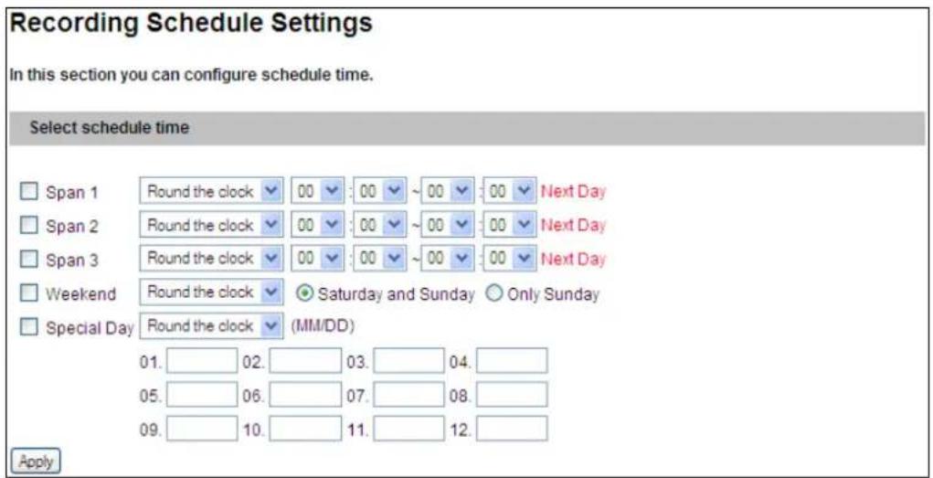
Figure 4-17
■ Span 1- Span 3: Set a different recording mode for each time frame during the day. Each day can be divided into 3 time frames, represented by Span 1 to Span 3.
■ Weekend: Enable this option to start monitoring all day on the weekend and select the recording mode to be used. Define whether your weekend includes Saturday and Sunday or Only Sunday.
■ Special Day: Set the recording mode on a specified day.
4.5 Network
The Network section includes some basic but important network configurations that enable the GV-Hybrid LPR Camera 20R / 10R / GV-IP LPR Camera 5R to be connected to a TCP/IP network.
4.5.1 LAN Configuration
According to your network environment, select among Static IP, DHCP and PPPoE.
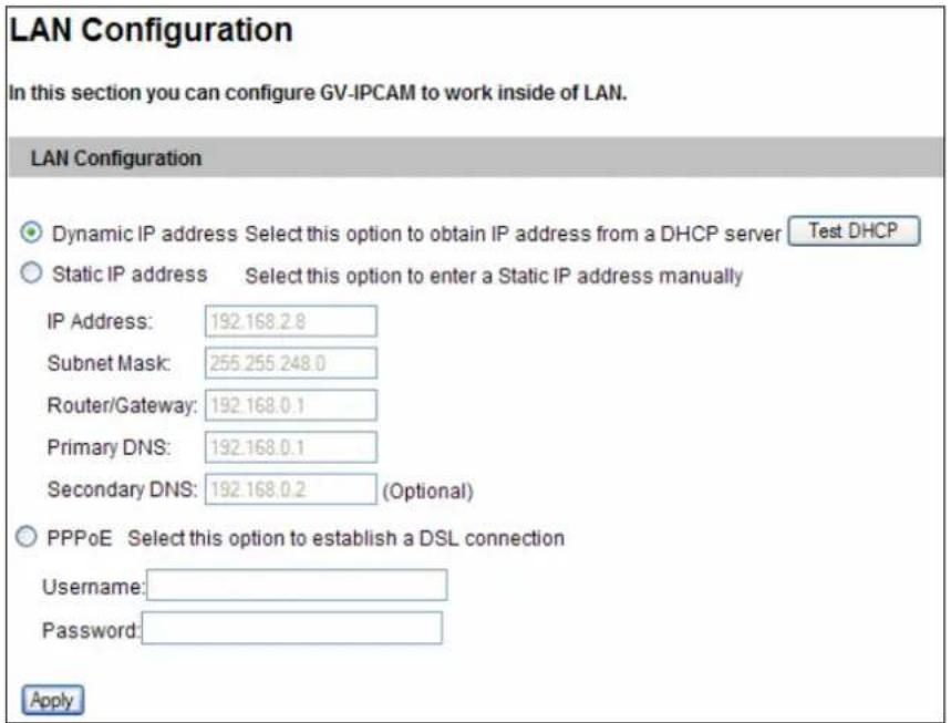
Figure 4-18
[LAN Configuration]
■ Dynamic IP address: The network environment has a DHCP server which will automatically assign a dynamic IP address to the camera. Click the Test DHCP to see the currently assigned IP address or look up the address using GV-IP Device Utility.
■ Static IP address: Assign a static IP or fixed IP to the camera. Type the camera's IP address, Subnet Mask, Router/Gateway, Primary DNS server and Secondary DNS server.
| Parameters Default | |
| IP address 192.168.0.10 | |
| Subnet Mask 255.255.255.0 | |
| Router/Gateway | 192.168.0.1 |
| Primary DNS server 192.168.0.1 | |
| Secondary DNS server 192.168.0.2 |
■ PPPoE: The network environment is xDSL connection. Type the Username and Password provided by ISP to establish the connection. If you use the xDSL connection with dynamic IP addresses, first use the DDNS function to obtain a domain name linking to the camera's changing IP address.
For details on Dynamic DNS Server Settings, see 4.5.2 Advanced TCP/IP.
4.5.2 Advanced TCP/IP
This section introduces the advanced TCP/IP settings, including DDNS Server, HTTP port, streaming port and UPnP.
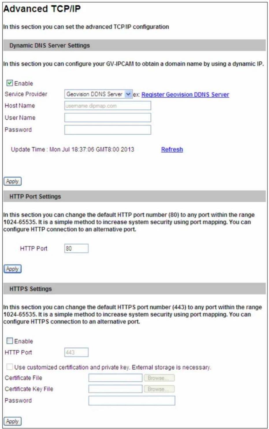
Figure 4-19A
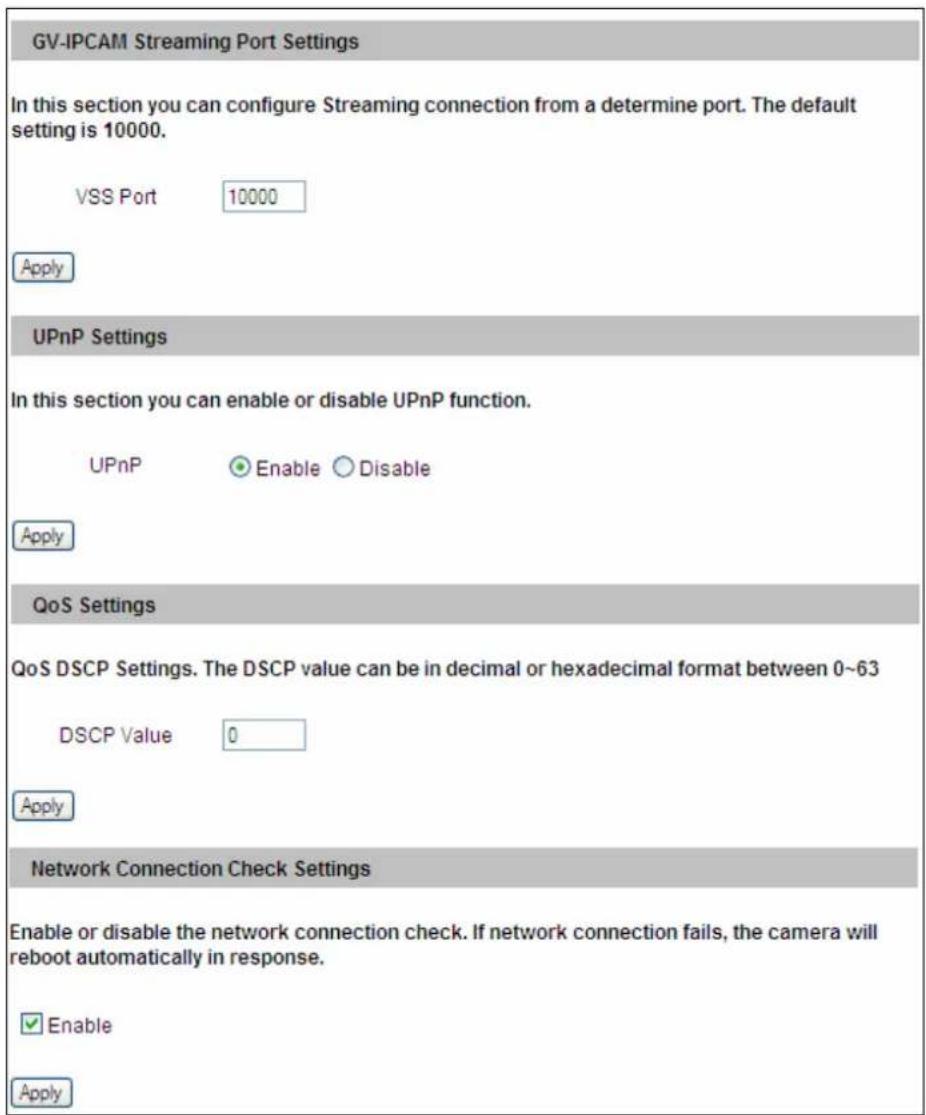
Figure 4-19B
[Dynamic DNS Server Settings]
DDNS (Dynamic Domain Name System) provides a convenient way of accessing the GV-Hybrid LPR Camera 20R / 10R / GV-IP LPR Camera 5R when using a dynamic IP. DDNS assigns a domain name to the camera, so that the Administrator does not need to go through the trouble of checking if the IP address assigned by DHCP Server or ISP (in xDSL connection) has changed.
Before enabling the DDNS function, you should apply for a Host Name from the DDNS service provider's website. There are 2 providers listed in the GV-Hybrid LPR Camera 20R / 10R / GV-IP LPR Camera 5R: GeoVision DDNS Server and DynDNS.org.
To enable the DDNS function:
- Enable: Enable the DDNS function.
- Service Provider: Select the DDNS service provider you have registered with.
- Host Name: Type the host name used to link to the GV-Hybrid LPR Camera 20R / 10R / GV-IP LPR Camera 5R. For the users of GeoVision DDNS Server, it is unnecessary to fill the field because the system will detect the host name automatically.
- User Name: Type the user name used to enable the service from the DDNS.
- Password: Type the password used to enable the service from the DDNS.
- Click Apply.
[HTTP Port Settings]
The HTTP port enables connecting the GV-Hybrid LPR Camera 20R / 10R / GV-IP LPR Camera 5R to the Web. For security integration, the Administrator can hide the server from the general HTTP port by changing the default HTTP port 80 to a different port one within the range of 1024 through to 65535.
[HTTPS Settings]
By enabling the Hypertext Transfer Protocol Secure (HTTPS) settings, you can access the GV-Hybrid LPR Camera 20R / 10R / GV-IP LPR Camera 5R through a secure protocol. Note the customized certification function is currently not supported in GV-IP LPR Camera 5R.
[Camera Streaming Port Settings]
The VSS port enables connecting the GV-Hybrid LPR Camera 20R / 10R / GV-IP LPR Camera 5R to the GV-System. The default setting is 10000.
[UPnP Settings]
UPnP (Universal Plug & Play) is a networking architecture that provides compatibility among networking equipment, software and peripherals of the 400+ vendors that are part of the Universal Plug and Play Forum. It means that they are listed in the network devices table for the operating system (such as Windows XP) supported by this function. Enabling this function, you can connect to the GV-Hybrid LPR Camera 20R / 10R / GV-IP LPR Camera 5R directly by clicking on the camera listed in the network devices table. This function is enabled by default.
[QoS Settings]
The Quality of Service (QoS) is a bandwidth control mechanism that guarantees delay-sensitive data flows such as voice and video streams, obtain a certain amount of bandwidth to keep the streaming smooth.
To apply QoS to GV-Hybrid LPR Camera 20R / 10R / GV-IP LPR Camera 5R, all network routers must support QoS and QoS must be enabled on these devices. To enable the QoS on the camera, enter a Differentiated Services Code Point (DSCP) value. This value is a field in an IP packet that enables different levels of services for the network traffic. When the video stream from GV-Hybrid LPR Camera 20R / 10R / GV-IP LPR Camera 5R reaches a router, the DSCP value will tell the router what service level should be applied, e.g. the bandwidth amount. This value ranges from 0 to 63 in decimal format. The default value is 0 which means QoS is disabled. Click Apply to finish.
[Network Connection Check Settings]
When the network connection check is enabled, the GV-Hybrid LPR Camera 20R / 10R / GV-IP LPR Camera 5R will check for Internet connection and reboots automatically when it is disconnected from the Internet. This function is enabled by default.
4.5.3 IP Filtering
The Administrator can set IP filtering to restrict access to the GV-Hybrid LPR Camera 20R / 10R / GV-IP LPR Camera 5R.
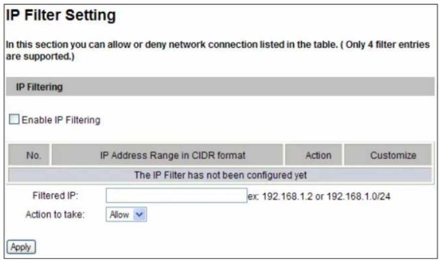
Figure 4-20
To enable the IP Filter function:
- Enable IP Filtering: Enable the IP Filtering function.
- Filtered IP: Type the IP address from which you want to restrict the access.
- Action to take: Select the action of Allow or Deny to be taken by the IP address(es) you have specified.
- Click Apply.
4.5.4 SNMP Settings
The Simple Network Management Protocol (SNMP) allows you to monitor the status of the GV-Hybrid LPR Camera 20R / 10R / GV-IP LPR Camera 5R through SNMP network management software.
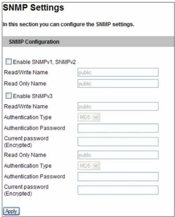
Figure 4-21
To allow management of SNMP software:
- Select Enable SNMPv1 SNMPv2c to enable the function.
- To enable access to Read/Write Name, type a community string. This will serve as a password to allow read and write access to the GV-Hybrid LPR Camera 20R / 10R / GV-IP LPR Camera 5R from the SNMP software.
- To enable Read Only Name, type a community string to allow read-only access to the GV-Hybrid LPR Camera 20R / 10R / GV-IP LPR Camera 5R from the SNMP software.
- For a more secured connection, select Enable SNMPv3 to enable SNMP version 3.
- To enable access to Read/Write Name, type a community string.
-
Select an Authentication Type to be used for SNMP requests.
-
Type the Authentication Password and Current Password (Encrypted). You will need to type these passwords in the SNMP software to be able to access the GV-Hybrid LPR Camera 20R / 10R / GV-IP LPR Camera 5R.
- To enable access to Read Only Name, type a community string to allows read-only access to the GV-Hybrid LPR Camera 20R / 10R / GV-IP LPR Camera 5R, and set up the Authentication Type, Authentication Password and the Current Password (Encrypted).
- Click Apply to save the settings.
4.6 Management
The Management section includes the settings of data and time, GPS Maps and user account. Also you can view the firmware version and execute certain system operations.
4.6.1 Date and Time Settings
The date and time settings are used for date and time stamps on the image.
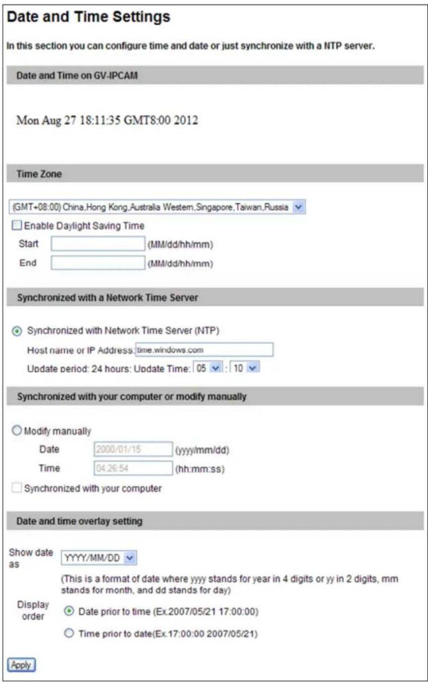
Figure 4-22
[Date & Time on GV-IPCAM] Displays the current date and time on the GV-Hybrid LPR Camera 20R / 10R / GV-IP LPR Camera 5R.
[Time Zone] Sets the time zone for local settings. Select Enable Daylight Saving Time to automatically adjust the GV-Hybrid LPR Camera 20R / 10R / GV-IP LPR Camera 5R for daylight saving time. Type the Start Time and End Time to enable the daylight saving function.
[Synchronized with a Network Time Server] By default, the GV-Hybrid LPR Camera 20R / 10R / GV-IP LPR Camera 5R uses the timeserver of time.windows.com to automatically update its internal clock every 24 hours. You can change the host name or IP setting to the timeserver of interest. To change the time of automatic update, use the drop-down lists to specify the time.
[Synchronized with your computer or modify manually] Manually changes the camera date and time or synchronize its date and time with those of the local computer.
[Date and time overlay setting] Select the display format of date and time stamps on the image. For this function to work, you must also enable the Overlaid with date stamps and Overlaid with time stamps options in Figure 4-2B.
Note: When connecting to GV-System (V8.5.7.0 or later), the Daylight Saving Time of GV-Hybrid LPR Camera 20R / 10R / GV-IP LPR Camera 5R can be synchronized automatically with that of GV-System by enabling Automatically adjust DST (Configure button < Camera Install < IP Camera Install).
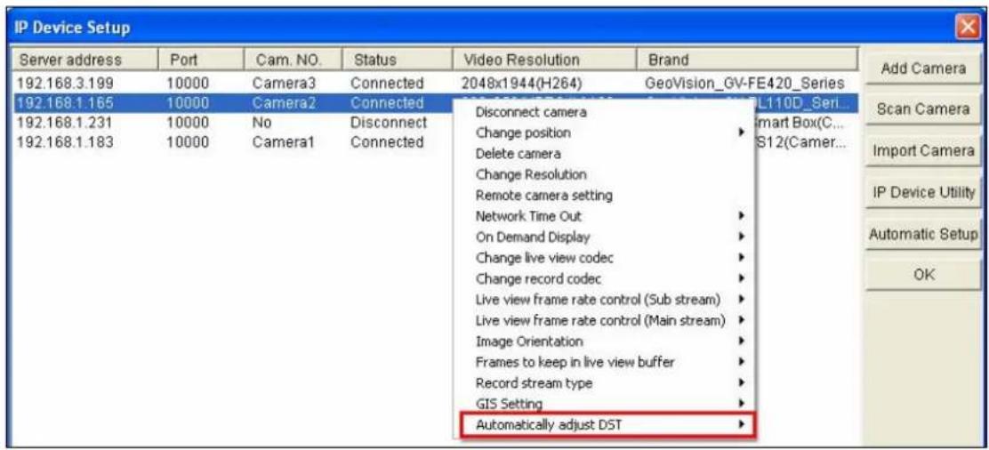
Figure 4-23
4.6.2 GPS Maps Settings
The Maps Settings allows you to see the location of your GV-Hybrid LPR Camera 20R / 10R / GV-IP LPR Camera 5R on Google maps, without the need of a GPS device.
To see the location of your GV-Hybrid LPR Camera 20R / 10R / GV-IP LPR Camera 5R on maps:
- It is required to sign up for a Google Maps API key before using the Google Maps. Click Link to the Google Maps API.
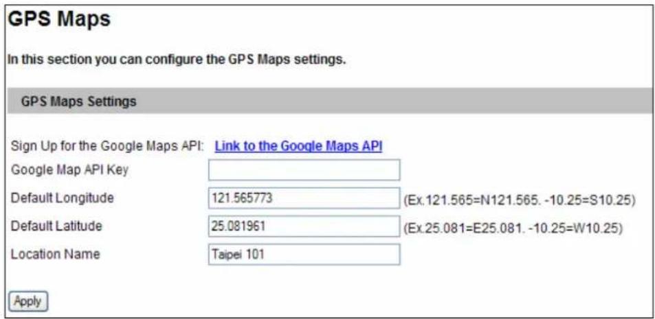
Figure 4-24
- Enter the registered Maps API Key, the longitude and latitude of your camera location, and location name. Click Apply to enable this function.
- Open the control panel of the Live View window.
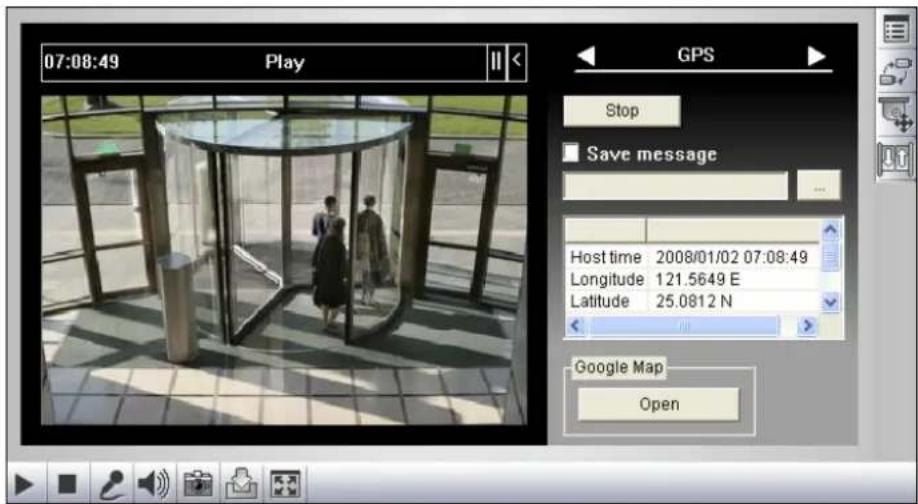
Figure 4-25
4. Click Open. A warning message appears.
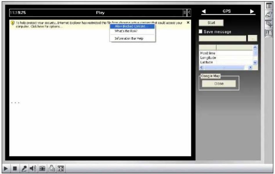
Figure 4-26
- Right-click the warning message and select Allow Blocked Content. The map will be displayed. The 🔒 icon indicates the location of your camera. In the upper right corner you have options to view different map formats, such as Satellite and Hybrid.
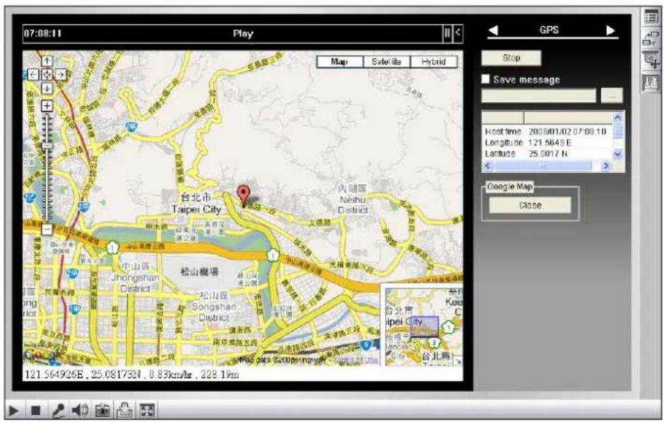
Figure 4-27
4.6.3 Storage Settings
Note this function is not available for GV-Hybrid LPR Camera 20R / 10R.
The GV-IP LPR Camera 5R can support memory cards for video and audio recordings. You need to format the storage device by using the following Storage Settings.
Important: This function is currently not supported in GV-IP LPR Camera 5R.
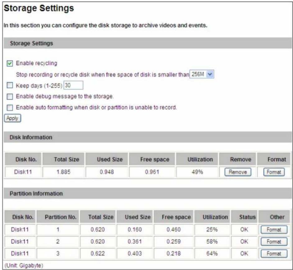
Figure 4-28
[Storage Settings]
■ Enable recycling: If Enable recycling is selected, when the space of the storage device is lower than the specified space, the system will overwrite the oldest recorded files. If Enable recycling is not selected, the system will stop recording when the specified space is reached.
- Keep days (1-255): Specify the number of days to keep the files from 1 day to 255 days. When both Keep days and Enable recycling are selected, the system applies whichever condition comes first. For example, if the specified smallest amount of storage space comes earlier than the designated keep days, then recycle is applied first.
■ Enable debug message to the storage: Select this option to store debug messages (log information) to an inserted storage device.
■ Enable auto formatting when disk or partition is enable to record: Select this option for the camera to automatically format the storage device when there is error during recording.
[Disk Information]
This section shows the details of the attached storage device. Use the Format/Remove button to format or unload a storage device. For detail steps, see Partition Information below.
[Partition Information]
This section shows the partition details of the attached storage device.
To add a storage device:
-
Insert the storage device to the camera.
-
Click the Format button.
-
After the format is complete, the partition information will display. The maximum space for one partition is 200 GB.
To remove a storage device:
- Click the Remove button.
- When you are prompted to ensure the action, click Yes. The page will be refreshed and the partition information will be cleaned.
- Remove the storage device from the camera.
The storage device status is shown in the status column:
| Status Description | |
| Formatting The | storage device is being formatted. |
| Unknown The | camera can not recognize the format of the storage device or the |
| OK Storage formatting is successful. | |
| Try Mount The | camera is attempting to connect to the storage device. |
| Error File There | is a recording error in the storage device. All the recording data is |
| Read Only The | storage device cannot be written due to abnormal power disruption. |
| Repairing The | system is attempting to repair the recording data. |
Note:
- If Enable Recycling is selected, the available space of the storage device must be higher than the space you specified at the Stop recording or recycle disk when free space of disk is smaller than x option. Otherwise no video will be recoded.
- The recording data may be lost if you remove the storage device during recording.
- If you do not remove the storage device properly, the data cannot be read in another computer. In this case, re-plug the storage device back to the camera. The system will repair the data automatically. When the system is repairing the data, the Remove field will display "Repairing".
4.6.4 User Account
You can change the login name and password of Administrator and Guest accounts.
- The default Administrator login name and password are admin.
- The default Guest login name and password are guest. To allow a Guest user log in without entering the username and password, select Disable authentication for guest account.
• To remain logged in after reboot, select Disable auto logout after reboot.
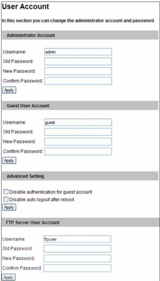
Figure 4-29
Note: You can also access this User Account interface simply by executing a CGI command. See Appendix A.
4.6.5 Log Information
The log contains dump data that is used by service personnel for analyzing problems.
![Log Information In this section you can see all system activities. Startup time log In this section you can see latest booting time of system. [81]Thu Jul 25 05:04:49 2013 [9]Thu Jul 25 05:35:42 2013 [9]Thu Jul 25 06:06:34 2013 [9]Thu Jul 25 06:37:25 2013 [9]Thu Jul 25 07:08:17 2013 [9]Thu Jul 25 07:39:08 2013 [9]Thu Jul 25 08:10:01 2013 [9]Thu Jul 25 08:40:52 2013 Debug Messages This section shows the data used for debugging. Jul 29 17:14:16 Video Server[979]: (1080) connect_bkserver [322]: "Connect to pIF=192.168.3.64 port=30000\n" Jul 29 17:14:16 Video Server[979]: (1080) Connect[134]: "[Connect] bkserver:192.168.3.64 usr:admin pwd:1\n" Jul 29 17:14:16 Video Server[979]: (1077) connect_video_gateway [222]: "Video-Gateway thread: connect() failed\n" Jul 29 17:14:16 Video Server[979]: (1080) connect_bkserver [332]: "Can't connect to Backup Server:192.168.3.64:30000\n" Jul 29 17:14:16 Video Server[979]: (1080) connect_all_bkserver [395]: "Retry sUser.username = admin sUser.password = 1 username = admin password = 1\n" Jul 29 17:14:17 thttpd[907]: (907) httpd_parse_request [1973]: "remote client[127.0.0.1] request URL[/DeviceInfo.htm]" Jul 29 17:14:17 sipd: (980) show_gvpacket[191]: "sync:1450132839, size:888, cmd_id:0xa002, version:4097" ", VS's mac1 [00:00:00:00:00:00], ip[], source ip[192.168.4.13], source port:15000" ", PC's MAC[00:00:00:00:00:00]\n" Jul 29 17:14:17 sipd: (980) main[1340]: "Reply Temperature: 42.5 (C) / 108.5(F)\n" Jul 29 17:14:17 sipd: (980) show_reply[405]: "reply - ip [192.168.2.89], mac1[00:13:E2:FF:OA:65], svr_type[729]\n" Jul 29 17:14:19 Video Server[979]: (1077) connect_video_gateway [222]: "Video-Gateway thread: connect() failed\n" Jul 29 17:14:19 Video Server[979]: (1077) video_gateway_server_thread Clear](/content/2026/06/1146107/images/98d6147a5e0669979979dccf002ec62896a29a81a5f5f0175a344412d2628e04.jpg)
Figure 4-30
4.6.6 System Log
Note this function is not available for GV-Hybrid LPR Camera 20R / 10R.
The System Log records the events in the four types of logs: System Event, Monitoring Event and Login/Logout Event. With the System Log, you can search and obtain the detailed information of an event. To use the System Log, an SD card is required to be inserted to the GV-IP LPR Camera 5R.
Important: This function is currently not supported in GV-IP LPR Camera 5R.
- For the first-time user of the System Log, click Create to create a system log database (access file) on the inserted SD card.
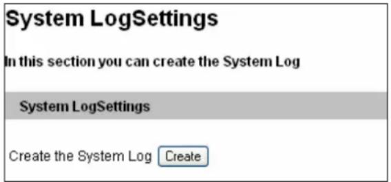
Figure 4-31
Note: If you have created the system log database on the SD card, clicking Create again will clean your System Log.
- Select the log type System Event, Monitor Event or Login/Logout Event from the left menu of the Web interface.
- Select the filtering criteria. For example, we want to know the login and logout information during a specific period of time.
- Click Query. The filtering results may look like the figure below.
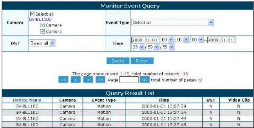
Figure 4-32
4.6.7 Tools
This section allows you to execute certain system operations and view the firmware version.
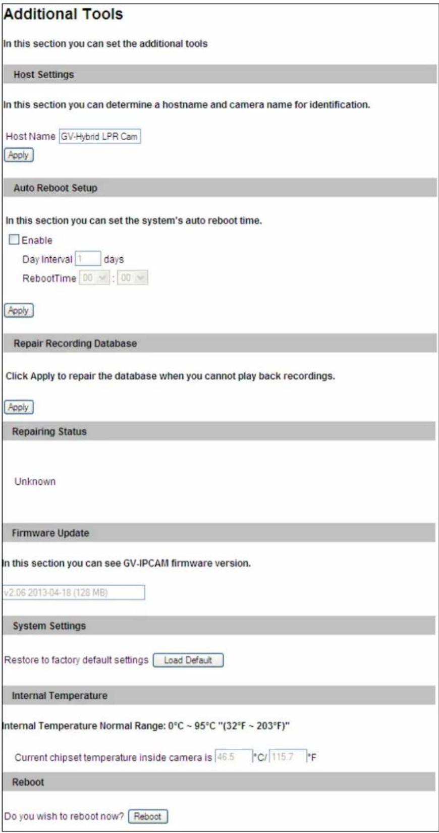
Figure 4-33
[Host Settings] Enter a descriptive name for the camera.
[Auto Reboot Setup] Select Enable to activate automatic reboot and specify the time for reboot in the sub fields below.
■ Day Interval: Type the day interval between the reboots.
■ Reboot Time: Use the drop-down list to specify the time for automatic reboot.
[Repair Recording Database] Click Apply to repair the database when errors occur while playing back the recordings with the Remote ViewLog player. Problems can occur when there are errors in firmware or damages to the SD card. Note this function is only available for GV-IP LPR Camera 5R.
[Repairing Status] This field displays the repairing status of database. Note this function is currently not supported in GV-IP LPR Camera 5R.
[Firmware Update] This field displays the firmware version of the camera.
[System Settings] Click the Load Default button to restore the factory default settings.
Note: After applying the default function, the default network connection will be DHCP or fixed IP (192.168.0.10) if the router does not support DHCP. Re-configure your network settings if necessary.
[Internal Temperature] This field displays the current chipset temperature inside the camera.
[Reboot] Click the Reboot button to reset the software configuration of the camera.
4.6.8 Language
You can select the language for the Web interface.
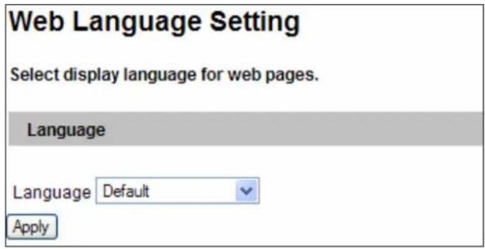
Figure 4-34
Use the Language drop-down list to select a language for the Web interface. By default, the language on the Web interface will be the same with the one used for the operating system.
Chapter 5 Advanced Applications
This chapter introduces more advanced applications.
5.1 Upgrading System Firmware
GeoVision periodically updates the latest firmware to the company website. You can update your camera firmware through the Web interface or GV-IP Device Utility included in the Software DVD.
Important Notes before You Start
Before you start updating the firmware, please read these important notes:
- While the firmware is being updated, the power supply must not be interrupted.
WARNING: The interruption of power supply during updating causes not only update failures but also damages to your camera. In this case, please contact your sales representative and send your device back to GeoVision for repair.
- Do not turn the power off within 10 minutes after the firmware has been updated.
- If you use GV-IP Device Utility for firmware upgrade, the computer used to upgrade firmware must be under the same network as the GV-Hybrid LPR Camera 20R / 10R / GV-IP LPR Camera 5R.
- Stop monitoring the GV-Hybrid LPR Camera 20R / 10R / GV-IP LPR Camera 5R.
- Stop all the remote connections including Center V2, VSM, ViewLog Server and 3GPP/RTSP.
- Stop the connection to GV-System.
- If firmware upgrade fails, you will need to restore the camera to its default settings. For details, see 5.3 Restoring to Factory Default Settings.
5.1.1 Using the Web Interface
- In the Live View window, click the Show System Menu button (No. 8, Figure 3-2) and select Remote Config. This dialog box appears.
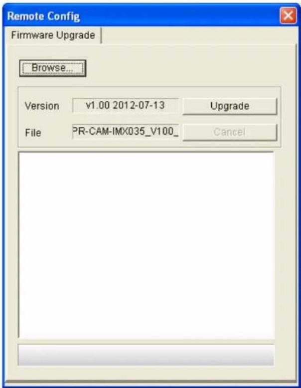
Figure 5-1
- Click the Browser button to locate the firmware file (.img) saved at your local computer.
- Click the Upgrade button to start upgrading.
5.1.2 Using the GV-IP Device Utility
The GV-IP Device Utility provides a direct way to upgrade the firmware to multiple GV-Hybrid LPR Camera 20R / 10R / GV-IP LPR Camera 5R. Note the computer used to upgrade firmware must be under the same network with the cameras.
- Insert the Software DVD, select GV IP Device Utility, and follow the onscreen instructions to install the program.
- Double-click the GV IP Device Utility icon created on your desktop. This dialog box appears.
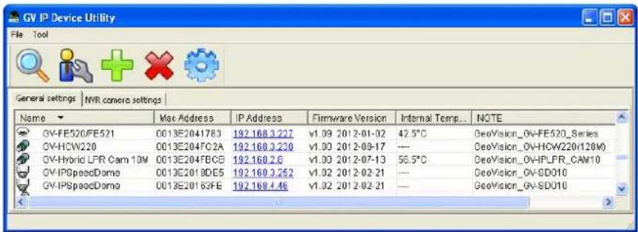
Figure 5-2
-
Click the Search button to locate the IP devices on the LAN or click the New button and assign the IP address to locate a GV-Hybrid LPR Camera 20R / 10R / GV-IP LPR Camera 5R on the network. Or highlight one IP device in the list and click the Delete button to remove it.
-
Click on the IP address of the camera and select Configure. This dialog box appears.
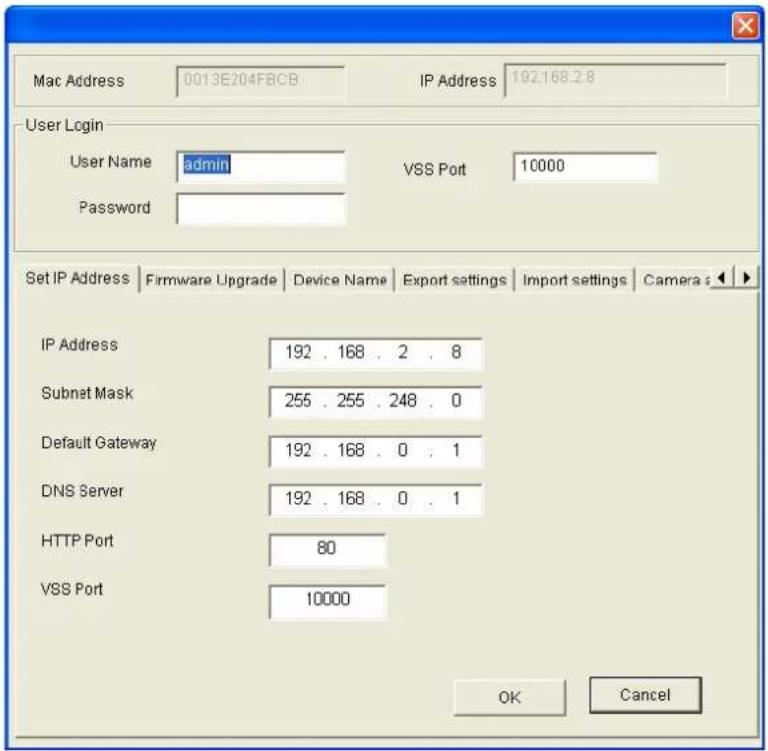
Figure 5-3
- Click the Firmware Upgrade tab. This dialog box appears.
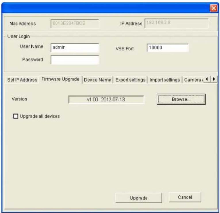
Figure 5-4
-
Click the Browse button to locate the firmware file (.img) saved at your local computer.
-
If you like to upgrade all the GV-Hybrid LPR Cameras 20R / 10R / GV-IP LPR Camera 5R in the list, check Upgrade all devices.
- Type Password, and click Upgrade to start the upgrade.
5.2 Backing Up and Restoring Settings
With the GV-IP Device Utility included on the Software DVD, you can back up the configurations in the GV-Hybrid LPR Camera 20R / 10R / GV-IP LPR Camera 5R, and restore the backup data to the current unit or import it to another unit.
To back up the settings
- Run GV IP Device Utility and locate the desired camera. See Steps 1-3 in 5.1.2 Using the GV-IP Device Utility.
- Double-click the camera in the list. Figure 5-3 appears.
- Click the Export Settings tab. This dialog box appears.
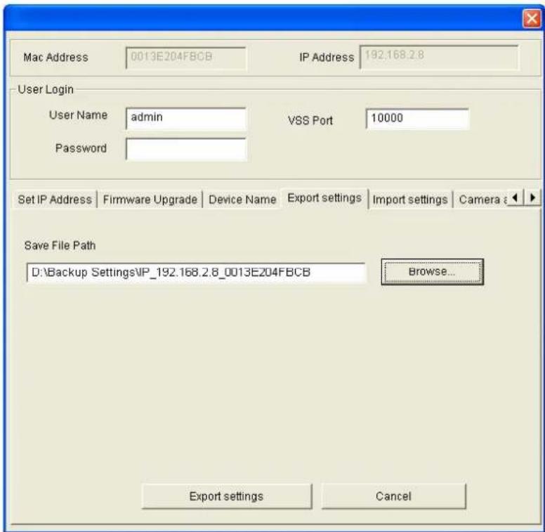
Figure 5-5
-
Click the Browse button to assign a file path.
-
Type Password, and click Export Settings to save the backup file.
To restore the settings
- In Figure 5-3, click the Import Settings tab. This dialog box appears.
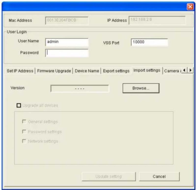
Figure 5-6
- Click the Browse button to locate the backup file (.dat).
- Select Upgrade all devices to import the settings into the same type of device in the same LAN. To import password settings and/or network settings, select Password Settings and/or Network settings.
- Click the Upgrade setting button to start restoring.
5.3 Restoring to Factory Default Settings
To restore the factory default settings, you can use the camera's Web interface or operate directly on the camera.
5.3.1 Using the Web Interface
For GV-Hybrid LPR Camera 20R / 10R / GV-IP LPR Camera 5R, follow the steps below to restore the factory default settings through the camera's Web interface.
- In the left menu of the Web interface, Click Tools.
- In System Settings field, click the Load Default button to restore the factory default settings.
5.3.2 Directly on the Camera
For GV-IP LPR Camera 5R, you can alternatively press the default button inside the camera.
- Keep the power and network cables connected to the camera.
- Loosen the camera's cover and remove the Silica Gel Bag.
- Press and hold the default button for 8 seconds.
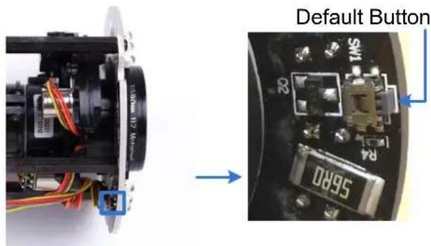
- Release the default button. When the process of loading default settings is completed, the camera reboots automatically.
- Insert a new Silica Gel Bag and fasten the camera's cover immediately.
5.4 Verifying Watermark
The watermark is an encrypted and digital signature embedded in the video stream during the compression stage, protecting the video from the moment of creation. Watermarking ensures that an image is not edited or damaged after it is recorded. To enable the watermark function, see Watermark Setting, 4.1.1 Video Settings.
The Watermark Proof is a watermark-checking program. It can verify the authenticity of the recording before you present it in court.
5.4.1 Accessing AVI Files
To verify watermark, access the recorded AVI files by one of the following methods:
- Use the File Save function (No. 6, Figure 3-2) to start recording on the local computer.
- Locate recorded files on the GV-System.
5.4.2 Running Watermark Proof
- Install Watermark Proof from the Software DVD. After installation, a WMProof icon is created on your desktop.
- Double-click the created icon. The Water Mark Proof window appears.
- Click File from the menu bar, select Open and locate the recording (.avi). The selected recording is then listed on the window. Alternatively, you can drag the recording directly from the storage folder to the window.
- If the recording is unmodified, a check mark will appear in the Pass column. On the contrary, if the recording is modified or does not contain watermark during recording, a check mark would appear in the Failed column. To review the recording, double-click the listed file on the window.
5.4.3 The Watermark Proof Window
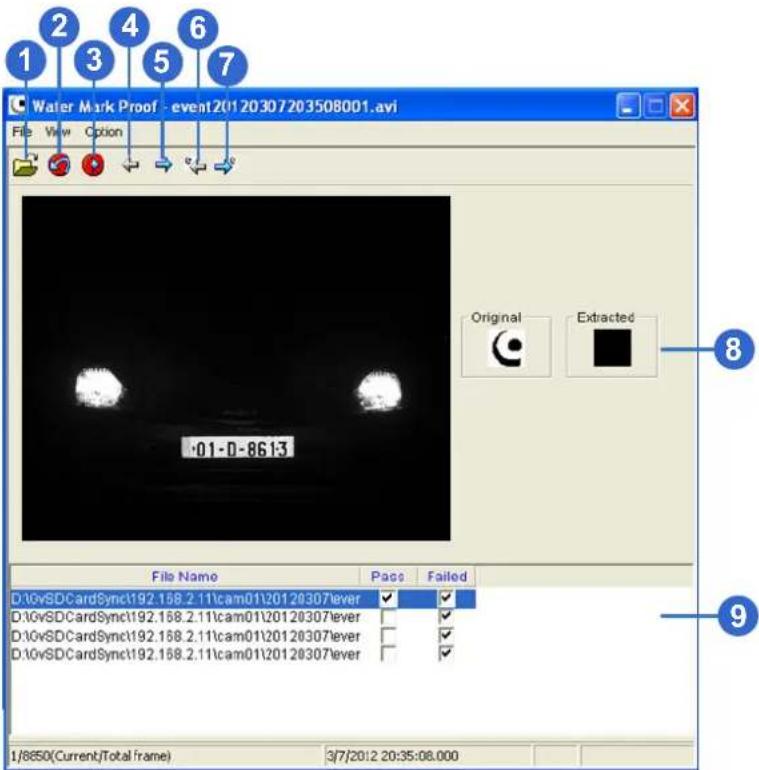
Figure 5-7
The controls in the window:
| No. | Name Description | |
| 1 | Open File Opens the recording. | |
| 2 | First Frame Goes to the first frame of the file. | |
| 3 | Play Plays the file. | |
| 4 | Previous Frame Goes to the previous frame of the file. | |
| 5 | Next Frame Goes to the next frame of the file. | |
| 6 | Previous Watermarked Frame | Goes to the previous frame that contains watermark. |
| 7 | Next Watermarked Frame Goes to the next frame that contains watermark. | |
| 8 | Original vs. Extracted | The Extracted icon should be identical with the Original icon. If not, it indicates the recording has been tampered. |
| 9 | File List Displays the proof | results. |
Chapter 6 DVR Configurations
The GV-System provides hybrid solution, integrating the digital videos from GV-Hybrid LPR Camera 20R / 10R / GV-IP LPR Camera 5R with other analog videos. For digital videos, the GV-System provides the complete video management, such as video viewing, playback, alert settings and almost every feature of the system. The following is the integration specifications:
- GV-System version 8.5.7.0 or later is required for connection with the GV-Hybrid LPR Camera 20R / 10R.
- GV-System version 8.5.8.0 or later is required for connection with the GV-IP LPR Camera 5R.
- The GV-Hybrid LPR Camera 20R / 10R / GV-IP LPR Camera 5R allows for up to 8 streams of connection.
- When a GV-Hybrid LPR Camera 20R / 10R / GV-IP LPR Camera 5R is connected to IE browser or any other applications, it takes up 1 stream; when it is connected to GV-System, it takes up 2 streams.
Note:
- The above maximum number of streams is based on the camera's maximum resolution 1280 × 1024 and the codec H.264.
- By default, GV-Hybrid LPR Camera 20R / 10R / GV-IP LPR Camera 5R is in dual streams and will take up 2 streams when connected to GV-System.
- The hardware compression and the "Pre-Recording Using RAM" feature cannot work on the videos from GV-Hybrid LPR Camera 20R / 10R / GV-IP LPR Camera 5R. For details about the "Pre-Recording Using RAM" feature, see "System Configuration", Chapter 1, DVR User's Manual on the GV-NVR Software DVD.
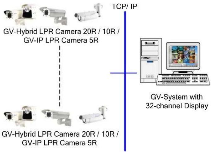
flowchart
graph TD
    A["GV-Hybrid LPR Camera 20R / 10R / GV-IP LPR Camera 5R"] --> B["TCP/ IP"]
    C["GV-Hybrid LPR Camera 20R / 10R / GV-IP LPR Camera 5R"] --> B
    D["GV-System with 32-channel Display"] --> E["Computer"]
    style A fill:#f9f,stroke:#333
    style C fill:#f9f,stroke:#333
    style D fill:#f9f,stroke:#333
    style B fill:#ccf,stroke:#333
    style E fill:#ccf,stroke:#333
Figure 6-1
6.1 Setting Up IP Cameras
Follow the steps below to manually connect your GV-Hybrid LPR Camera 20R / 10R / GV-IP LPR Camera 5R to GV-System.
Note: The following instructions are based on V8.5.7.0 software and user interfaces.
- On the GV-System's main screen, click the Configure button, select System Configure, select Camera Install and click IP Camera Install. This dialog box appears.
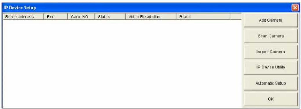
Figure 6-2
-
To automatically set up an IP camera, click Scan Camera to detect any IP cameras on the same LAN.
• To manually set up an IP camera, click Add Camera.
• To import IP cameras from the GV-IP Device Utility, click Import Camera.
• To map IP devices through the GV-IP Device Utility program, click IP Device Utility.
• To add all IP cameras within the IP address range, click Automatic Setup. -
Click Add Camera. This dialog box appears.
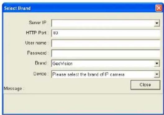
Figure 6-3
- Type the IP address, username and password of the camera. Modify the default HTTP port if necessary.
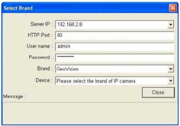
Figure 6-4
- Select GeoVision from the Brand drop-down list and select GV-IPLPR_CAM10 / GV-IPLPR_CAM 5 from the Device drop-down list. This dialog box appears.
Note: For the GV-Hybrid LPR Camera 20R, select GV-IPLPR_CAM10.
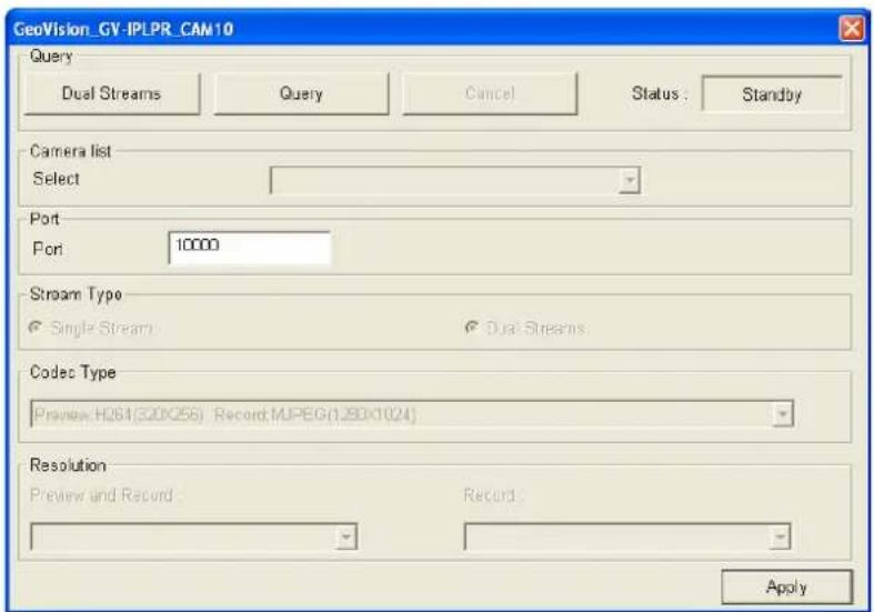
Figure 6-5
■ Dual Streams: Click this button to set the codec type to MJPEG in the main stream and to H.264 in the sub stream with the resolutions listed below.
■ Port: Modify the video streaming port number if necessary.
■ Stream Number: Click the Query button and select Single Stream or Dual Streams.
■ Codec type: The live view codec and resolution settings are displayed here.
■ Resolution: Select resolutions for preview and recording.
-
Click Apply. The camera is added to the list.
-
Click the listed camera, select Display position and select a channel number to map the camera to a channel on the GV-System.
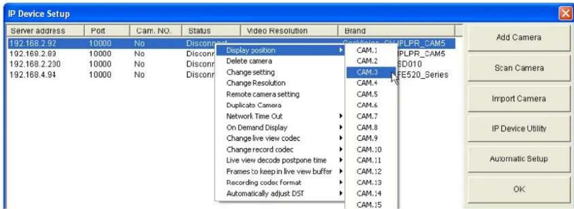
Figure 6-6
- The Status column now should display "Connected". Click OK. The dome view is displayed on the selected channel of GV-System.
6.1.1 Customizing Camera Settings
After the GV-Hybrid LPR Camera 20R / 10R / GV-IP LPR Camera 5R is connected and assigned with a display channel, you can configure the camera's settings such as frame rate, codec type and resolution. Right-click the camera to see the following list of options:
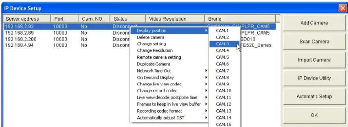
Figure 6-7
■ Change Setting: Changes the IP address, port number, username and password of the camera. This function is only available when the camera is disconnected.
■ Change Resolution: Changes the display ratio, live view resolution and record resolution.
■ Remote camera setting: Accesses the configuration interface of the connected camera.
■ Network Time Out: When network disconnection exceeds the specified time period, the camera status will be displayed as Connection Lost.
■ On Demand Display: Enables automatic adjustment of live view resolution and produces good image quality without causing high CPU usage.
■ Change live view codec: Changes the live view codec.
■ Change record codec: Changes the recording codec.
■ Live view decode postpone time: Specifies the number of milliseconds to postpone live view decoding. When network connection with the camera is unstable or when the time length between frames is not evenly distributed, postponing the live view decoding will make the video smoother.
■ Frames to keep in live view buffer: Specifies the number of frames to keep in the live view buffer.
■ Recording Codec Format: Specifies whether to record in standard or GeoVision type of JPEG, H.264 codec.
GIS Setting: Records the video with the GPS data. To record the GPS data, remember to also enable the GIS function of the GV-System (Configure button < Accessories < Enable Local GIS).
■ Automatically Adjust DST: If enabled, the time on the camera's Web interface will be synchronized with the time of the GV-System when DST period starts or ends on the GV-System.
6.2 Remote Monitoring with Multi View
You can monitor the live view of the GV-Hybrid LPR Camera 20R / 10R / GV-IP LPR Camera 5R using the Multi View.
Connecting to GV-Hybrid LPR Camera 20R / 10R / GV-IP LPR Camera 5R
The Multi View program is available in the GV-System applications, and is also included in the Software DVD as an independent program. The following is an example of running the Multi View through WebCam Server on the GV-System.
- To enable the remote access to the GV-System, click the Network button, select WebCam Server to display the Server Setup dialog box, and click OK to start the WebCam server.
- At the local computer, open the Web browser and type the IP address of the GV-System. The Single View page appears.
- Select Multi View and the desired viewing resolution. The valid user name and password are required for login. For the first-time user, you will be directed to the Download page. Install the Multi View program before you can run it.
- On the Multi View window, click the Edit Host button. The Edit Host window appears.
-
To create a host, click the New button. You need to create a group before creating a host.
-
Select GV-IP Camera, GV-IP Speed Dome from the Device drop-down list. Type the host name, IP address, user name and password of the camera. Modify the default VSS port 10000 if necessary.
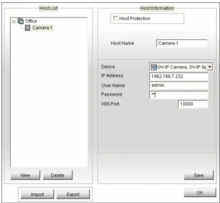
Figure 6-8
- Click Save to establish connection.
For details on the Multi View functions, see "Multi View Viewer", Chapter 8, DVR User's Manual on the GV-NVR Software DVD.
6.3 Remote Monitoring with E-Map
You can use the Remote E-Map to monitor the GV-Hybrid LPR Camera 20R / 10R / GV-IP LPR Camera 5R.
Creating an E-Map for the Camera
With the E-Map Editor, you can create an E-Map for the camera. The E-Map Editor is available in the two applications: Main System and E-Map Server. The following is an example of running the E-Map Editor from the Main System.
- Go to Windows Start menu, point to Programs, select GV folder and click E-Map Editor.
- To create an E-Map, click the Add Map button on the toolbar. A New Map file appears.
- Double-click the New Map file, and click the Load Map button on the toolbar to import a graphic file.
- To create a host, click the Add Host button on the toolbar and select Add Video Server.
- Right-click the created New Host in the Host View, and select Host Settings. This dialog box appears.
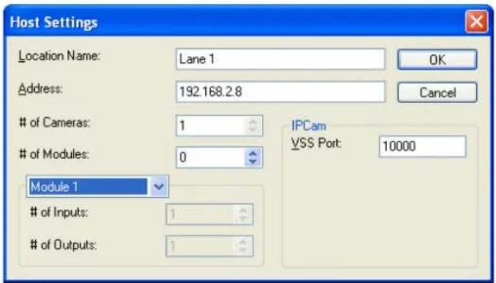
Figure 6-9
-
Give the camera a location name, and type its IP address (or domain name). Keep the default VSS port 10000, or modify it to match that of the camera.
-
Click OK to save the settings.
-
Expand the created host folder. Drag and drop the camera icon onto the imported E-Map.
-
Close the E-Map Editor. Click Yes when you are prompted to save the file.
For details on creating an E-Map file on the E-Map Server, see "E-Map Server", Chapter 9, DVR User's Manual on the GV-NVR Software DVD.
Connecting to the Camera
Depending on where you save the created E-Map file (GV-System, E-Map Server or Control Center), the steps to open the Remote E-Map window for monitoring may vary slightly. The following is the connection example when you store the E-Map file in the GV-System.
- To enable the remote access to the GV-System, click the Network button, select WebCam Server to display the Server Setup dialog box, and click OK to start the WebCam server.
- At the local computer, open the Web browser and type the address of the GV-System. The Single View page appears.
- Select Remote eMap. The valid user name and password are required for login. For the first-time user, you will be directed to the Download page. Install the E-Map program before you can run it.
- On the Remote E-Map window, click the Login button and select the camera host to access its videos. The valid user name and password are required to log in the camera.
For details on the Remote E-Map functions, see "The Remote E-Map Window", Chapter 9, DVR User's Manual on the GV-NVR Software DVD.
Chapter 7 CMS Configurations
This section introduces the related settings to enable connecting to the GV-Hybrid LPR Camera 20R / 10R / GV-IP LPR Camera 5R in the central monitoring stations Center V2 and VSM and Dispatch Server.
7.1 Center V2
The Center V2 can monitor the GV-Hybrid LPR Camera 20R / 10R / GV-IP LPR Camera 5R.
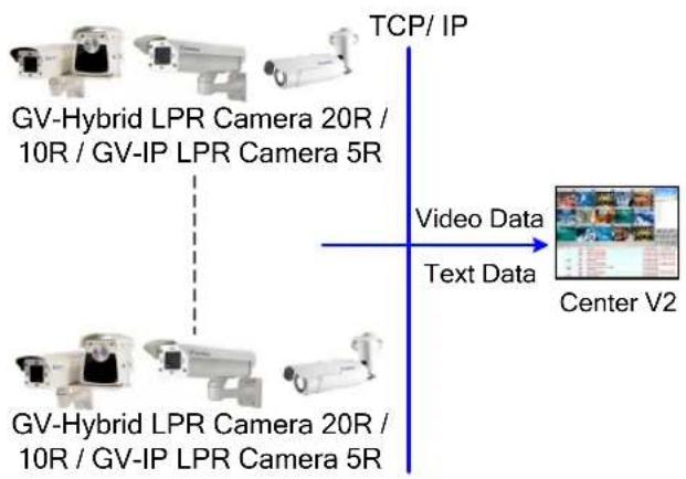
flowchart
graph TD
    A["GV-Hybrid LPR Camera 20R / 10R / GV-IP LPR Camera 5R"] --> B["Center V2"]
    C["GV-Hybrid LPR Camera 20R / 10R / GV-IP LPR Camera 5R"] --> B
    D["TCP/ IP"] --> E["Video Data"]
    D --> F["Text Data"]
Figure 7-1
To set the appropriate port connecting to the camera, click the Preference Settings button, select System Configure, click the Network tab, and check Accept connections from GV-Compact DVR, Video Server & IP Cam. Keep the default port 5551 for the Port 2 option, or modify it to match the Center V2 port on the camera.
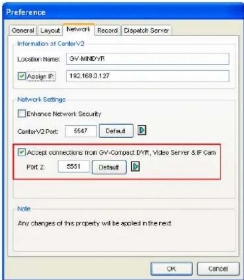
Figure 7-2
To define how to display the received video on motion detection, click the Preference Settings button and select System Configure. This dialog box appears.
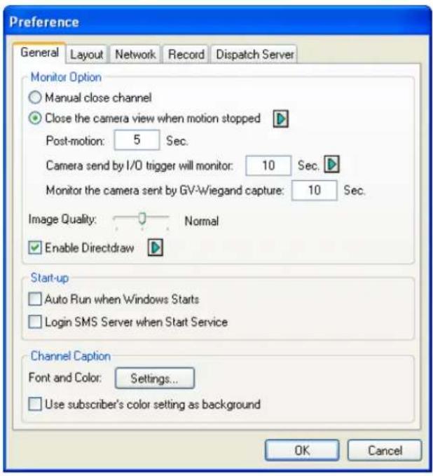
Figure 7-3
■ Manual close channel: Closes the triggered camera view manually.
■ Close the camera view when motion stopped: Closes the triggered camera view automatically when motion stops.
■ Post Motion: Specify the duration of the camera view remaining on the monitoring window after motion stops.
■ Camera send by I/O trigger will monitor: This feature is not functional for GV-Hybrid LPR Camera 20R / 10R / GV-IP LPR Camera 5R.
For further information on how to mange the received video from the camera, see GV-CMS Series User's manual.
7.2 VSM
The VSM can monitor the GV-Hybrid LPR Camera 20R / 10R / GV-IP LPR Camera 5R.
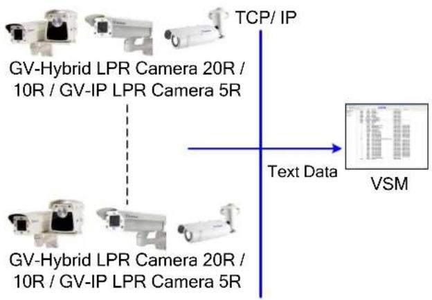
flowchart
graph TD
    A["GV-Hybrid LPR Camera 20R / 10R / GV-IP LPR Camera 5R"] -->|Text Data| B["VSM"]
    C["GV-Hybrid LPR Camera 20R / 10R / GV-IP LPR Camera 5R"] -->|Text Data| B
    D["TCP/ IP"] --> B
    style A fill:#f9f,stroke:#333
    style C fill:#f9f,stroke:#333
    style D fill:#ccf,stroke:#333
Figure 7-4
To set the appropriate port connecting to the camera, click Configure on the window menu, and select System Configure to display this dialog box. In the Connective Port field, keep the default value 5609 for the Port 2 option, or modify it to match the VSM port on the camera.
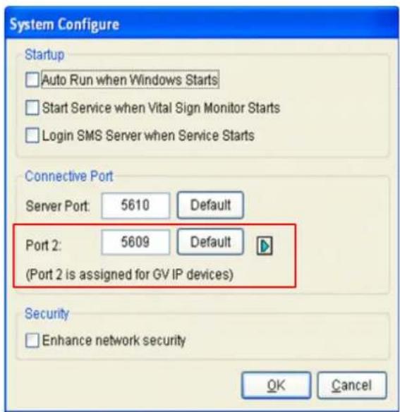
Figure 7-5
For further information on how to mange the received video from the camera, see GV-CMS Series User's manual.
7.3 Dispatch Server
The Dispatch Server can manage the GV-Hybrid LPR Camera 20R / 10R / GV-IP LPR Camera 5R, and distribute them to the Center V2.
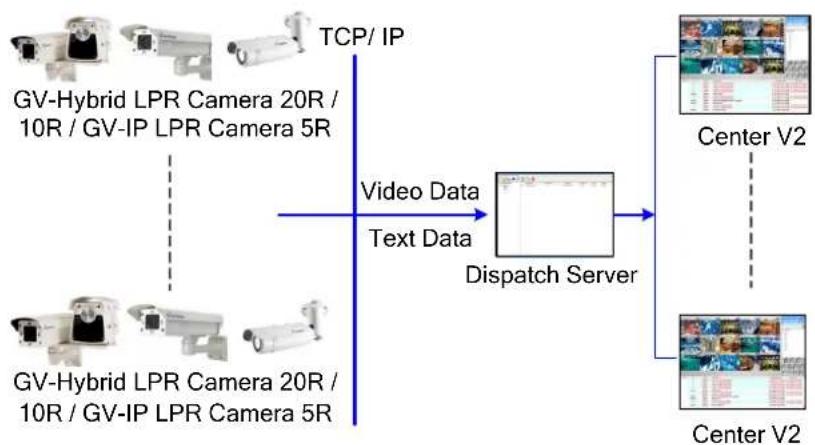
flowchart
graph TD
    A["GV-Hybrid LPR Camera 20R / 10R / GV-IP LPR Camera 5R"] -->|TCP/IP| B["Dispatch Server"]
    C["GV-Hybrid LPR Camera 20R / 10R / GV-IP LPR Camera 5R"] -->|Video Data Text Data| B
    B --> D["Center V2"]
    B --> E["Center V2"]
Figure 7-6
To enable connecting to the camera, click the Server Setting button on the toolbar, and enable Allow GV IP devices to login as subscriber from Port. Keep the default port 5551, or modify it to match the Center V2 port on the camera.
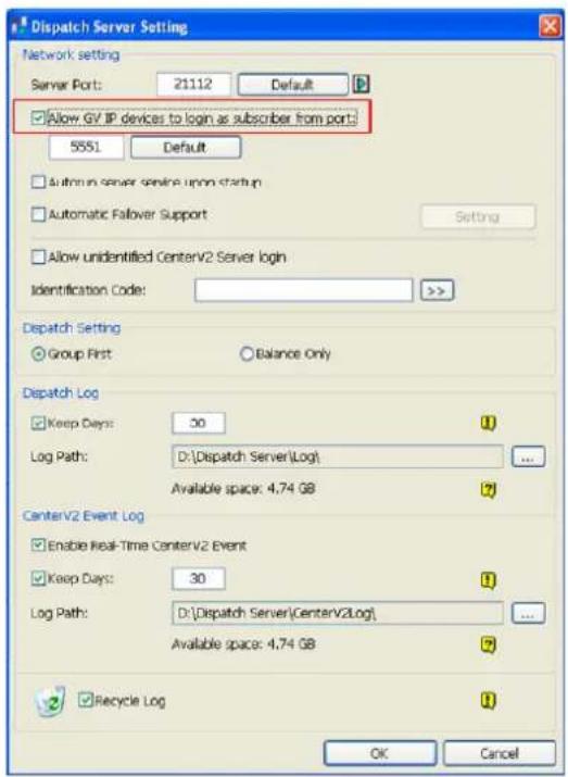
Figure 7-7
For further information on how to mange the received video from the camera, see GV-CMS Series User's manual
Chapter 8 Smart Device Connection
Using Android or Apple smart devices, you can receive live video streaming from the GV-Hybrid LPR Camera 20R / 10R / GV-IP LPR Camera 5R. The charts below list the GV mobile applications supporting the GV-Hybrid LPR Camera 20R / 10R / GV-IP LPR Camera 5R.
For the latest OS supported and detailed instructions, please visit our website: http://www.geovision.com.tw/english/5_4_iview.asp
| Smart Device View | OS Supported | Default Port |
| GV-Eye (HD) V1.3.0 | Android V2.2 to 4.3iOS 4.3.3 to 7.0.4 | VSS Port: 10000 |
| Supported Resolution and Codec | |
| MPEG4 | D1 (720 x 480) or below |
| MJPEG | 2M (1920 x 1080) or below |
| H.264 | |
| Supported Functions | |
| GV-IP Device | Live View, One-Way Audio, Snapshots, I/O Trigger, PTZ Control & Presets, Multiple Camera View |
Note:
- The default live view is stream 2 from the GV-IP Device with MJPEG codec and VGA (640 x 480) resolution.
- For MJPEG, resolution of 704 x 480 is not supported.
- The current version only supports Admin users to access the live view.
8.1 Android
Download GV-Eye from Android Market and install the application. The GV-Eye icon will appear on the desktop.
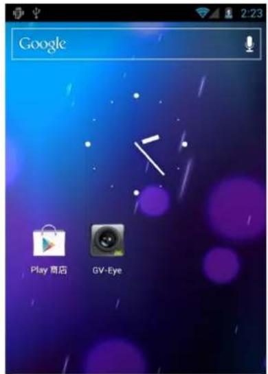
Figure 8-1
8.1.1 Connecting to the Camera
To connect your Android devices to the GV-Hybrid LPR Camera 20R / 10R / GV-IP LPR Camera 5R, follow the steps below.
-
Tap the GV-Eye icon on you mobile phone.
-
In the address book, tap the Add button to add the camera.
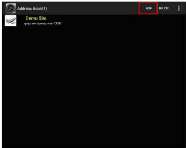
Figure 8-2
- Type the IP address, port number (default value is 10000), ID and password of the camera you want to access.
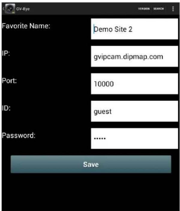
Figure 8-3
- Click Save to add the camera. The camera is added to the address book.
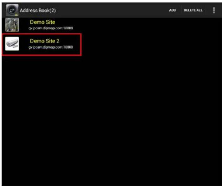
Figure 8-4
- In the address book, tap the desired camera to access the live view.
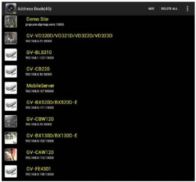
Figure 8-5
8.1.2 Accessing Live View
You can press the Menu button on the mobile phone to see or hide the connection information.
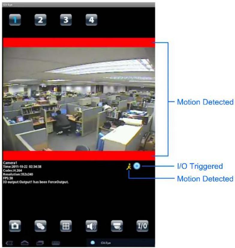
Figure 8-6
The following function buttons are available:
| Icon Name Function | ||
 | Channel number | Switches to a different channel. You can drag across the numbers to see more channels. This function is only supported by GV-Video Server and GV-Compact DVR. |
 | Snapshot Saves | the current image in the mobile device |
 | Dual Streams Switches between the video streams if the camera supports dual streams. | |
 | Screen division | Displays up to four channels on the same page if the camera supports multiple channels. This function is only supported by GV-Video Server and GV-Compact DVR. |
 | Audio Enables or | disables the audio function. G.711 and G.723 audio codec are supported. |
 | PTZ Control Enables | ables the PTZ function. A message will appear asking if you want to use Gesture Detector to control PTZ. Tap OK if you want to be able to drag across the live view screen to control the PTZ function in addition to using the PTZ control buttons on the bottom of the screen. ▲: Moves the camera toward different directions. ▲: Moves the camera back to Home position. ●: Zooms in and out. ●: Adjusts the focus. ●: Auto adjusts focus. ●: Adjusts the iris. ●: Moves the camera to a preset point by typing the preset number. ←→: See more PTZ function buttons. ▲: Exits the PTZ mode. |
 | I/O Device Tap a | number to force the output device to be triggered. The I/O icon will appear briefly when I/O is triggered. |
Note: The PTZ control and I/O device functions are only accessible on devices with PTZ control and I/O devices.
8.2 Apple
Download GV-Eye / HD from App Store and install the application. The GV-Eye / GV-EyeHD icon will appear on the desktop.
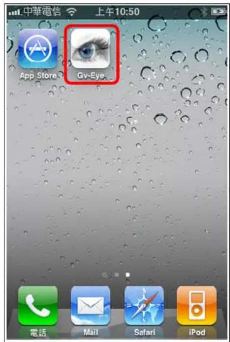
GV-Eye HD icon on iPad
Figure 8-7
8.2.1 Connecting to the Camera
To connect your iPhone, iPod Touch or iPad to the GV-Hybrid LPR Camera 20R / 10R / GV-IP LPR Camera 5R, follow the steps below.

-
Click the GV-Eye ic on your phone. The welcome page appears.
-
Tap the Add button. This page appears.
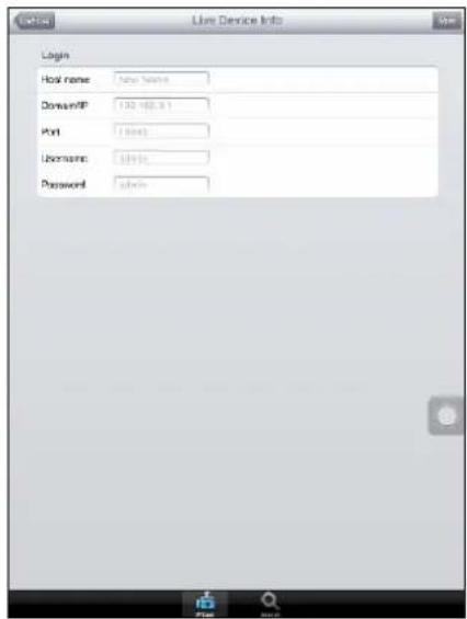
Figure 8-8
-
Enter the Host name, Domain/IP address, port number (default value is 10000), username and password to log into the camera.
-
Tap the Save button. The camera is added to the connection list.
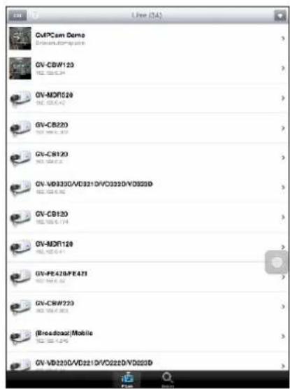
Figure 8-9
- In the connection list, tap the host name to access the live view.
8.2.2 Accessing Live View
You can tap the information button at the top-right corner to see the connection information.
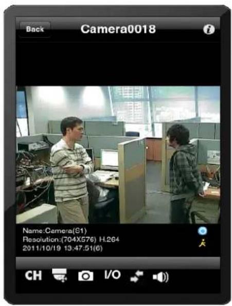
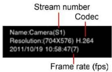

I/O Status (Not Triggerec)

I/O Triggered

Motion Detected
Figure 8-10
The buttons below are available when the iPhone, iPod Touch or iPad is positioned vertically.
| Icon Name Function | ||
 | Screen division | Displays up to four channels on the same page if the camera supports multiple channels. |
 | Z control Enables PTZ | control. Drag across the camera live view screen to adjust the camera position. The following buttons are available:Zooms in and out.Adjusts the focus.Moves the camera back to Home position.Adjusts the iris. This function is only supported by GV-SD010.Moves the camera to a preset point by typing the preset number. |
| Snapshot Saves the current image in the mobile device. | ||
 | Device Tap a number to force the output device to be triggered. The I/O icon will be highlighted briefly when I/O is triggered. | |
 | Stream change Switch the live view streams. | |
 | Audio Enables or disables the one-way audio function. G.711 and G.723 audio codec are supported. | |
Note: The PTZ control and I/O device functions are only accessible on devices with PTZ control and I/O devices.
Specifications
GV-Hybrid LPR Camera 20R / 10R
| Camera | ||
| Image Sensor | 1/3” B/W progressive scan CMOS | |
| Picture Elements | 1280 (H) x 1024 (V) | |
| Shutter Speed | Automatic, Manual (1/500 ~ 1/8000 sec) | |
| White Balance | Auto / Manual (2800K ~ 8500K) | |
| S/N Ratio | 50 dB | |
| Max. Speed | 120 km/h (75 mph) | |
| Lens | ||
| Megapixel | 1.3 MP | |
| Lens Type | Varifocal | |
| Focal Length | 5 ~ 50 mm | |
| Maximum Aperture | F/1.6 | |
| Mount | CS | |
| Image Format | 1/3” | |
| Operation | Focus | Manual (w/lock) |
| Zoom | Manual (w/lock) | |
| Iris | DC drive | |
| IR LED Quantity (for 10R only) | 4 high power IR LEDs | |
| IR Distance (for 10R only) | 6 ~ 12 m (19.7 ~ 39.4 ft) | |
| Max. Torque(Focus / Zoom Screws) | 0.049 N.m | |
| Operation | ||
| Video Compression | H.264, MJPEG | |
| Video Stream | Dual streams from H.264 and MJPEG | |
| Frame Rate | 30 fps at 1280 x 1024*The frame rate and the performance may vary depending on the number of connections and data bitrates (different scenes) | |
| Image Setting | Brightness, Contrast, Sharpness, Gamma, Image Orientation, Shutter Speed, Defog | |
| Operation | ||
| Audio Compression | G.711, AAC (Optional) | |
| Audio Support | Two-way audio | |
| Video Resolution | ||
| Main Stream | 4:3 | 1280 x 960, 640 x 480, 320 x 240 |
| 16.9 | 1280 x 720, 640 x 360, 448 x 252 | |
| 5:4 | 1280 x 1024, 640 x 512, 320 x 256 | |
| Sub Stream | 4:3 | 640 x 480, 320 x 240 |
| 16.9 | 640 x 360, 448 x 252 | |
| 5:4 | 640 x 512, 320 x 256 | |
| TV-Out | NTSC, PAL | |
| Network | ||
| Interface | 10/100 Base-T Ethernet, RJ-45 connector | |
| Protocol | DHCP, DynDNS, FTP, HTTP, HTTPS, NTP, ONVIF (Profile S), PSIA, QoS (DSCP), RTSP, SMTP, SNMP, TCP, UDP, UPnP, 3GPP/ISMA | |
| Mechanical | ||
| Lens Mounting | CS-Mount | |
| Temperature Detector | Yes | |
| Camera Angle Adjustment | Pan | 0° ~ 330° |
| Tilt | 0° ~ 90° | |
| Connectors | Power | PoE |
| Ethernet | RJ-45 | |
| Audio | 1 In (externally connecting a microphone)1 Out (Stereo phone jack, 3.5 mm / 0.14") | |
| Digital I/O | N/A | |
| TV-Out | BNC connector (640 x 480 resolution)*The TV-Out function only works in 640 x 480 resolution.For TV-Out to work properly, you must set the video resolution to 1280 x 1024 or lower. If both streams are enabled, the Sub Stream must be set to 640 x 480. | |
| LED Indicator | 1 LED (Status) | |
| General | |||
| Operating Temperature | -40°C ~ 50°C (-40°F ~ 122°F) | ||
| Humidity | 10% ~ 90% (non-condensing) | ||
| Power Source | PoE (IEEE802.3at) | ||
| Max. Power Consumption | 48 W | ||
| Dimensions | Camera Body | 10R | 317.5 x 108.5 x 230.57 mm (12.5 x 4.27 x 9.08") (with mounting base) |
| 20R | 317.5 x 284.2 x 290 mm (12.5 x 11.19 x 11.41") (including IR Illuminator / with mounting base) | ||
| Cable Length | 1 m (3.28 ft) | ||
| Weight | 10R | 3.2 kg (7.05 lb) | |
| 20R | 5.4 kg (11.9 lb) (including IR Illuminator) | ||
| Ingress Protection | IP67 | ||
| Vandal Resistance | IK10 for metal casing | ||
| Heater On | -40°C ~ 8°C (-40°F ~ 46.4°F) | ||
| Fan | Constantly On | ||
| Regulatory | CE, FCC, C-Tick, RoHS compliant | ||
| Power over Ethernet | |||
| PoE Standard | IEEE 802.3at Power over Ethernet / PD | ||
| PoE Power Supply Type | End-Span | ||
| PoE Power Output | DC 48 V, 600mA (34.2 W Max.) | ||
| Web Interface | |||
| Installation & Management | Web-based configuration | ||
| Firmware Upgrade | Remote upgrade through Web Browser GV-IP Device Utility included in the Software DVD | ||
| Access from Web Browser | Live View, Video Recording, Video Quality, Bandwidth Control, Image Snapshot, Audio, Picture in Picture, Picture and Picture, Privacy Mask, Tampering Alarm, Text Overlay | ||
| Language | Arabic / Bulgarian / Czech / Danish / Dutch / English / Finnish / French / German / Greek / Hebrew / Hungarian / Indonesian / Italian / Japanese / Lithuanian / Norwegian / Persian / Polish / Portuguese / Romanian / Russian / Serbian / Simplified Chinese / Slovakian / Slovenian / Spanish / Swedish / Thai / Traditional Chinese / Turkish | ||
| Applications | ||
| Network Storage | GV-NVR, GV-System, GV-Recording Server | |
| Smart Device Access | -GV-Eye for Android Smartphone, Tablet, iPhone and iPod Touch-GV-Eye HD for iPad | |
| Live Viewing | IE, GV-MultiView | |
| CMS Server support | GV-Control Center, GV-Center V2, GV-VSM | |
| IR Illuminator (for GV-Hybrid LPR Camera 20R) | ||
| IR LED Quantity | 12 high power IR LEDs | |
| IR Distance | 18 ~ 22 m (59.1 ~ 72.2 ft) | |
| Power Source | DC 90 V ~ 260 V | |
| Max. Power Consumption | 28 W | |
| Operating Temperature | -40°C ~ 60°C (-40°F ~ 140°F) | |
| Dimensions (L x W x H) | 170 x 160 x 158 mm (6.69 x 6.3 x 6.22") | |
| Weight | 2.2 g (4.85 lb) | |
| Conduit | Cable Entry | G(PF) 1/2" thread |
| Thread Diameter | 20.4 mm (0.8") | |
| GV-PA481 | ||
| PoE Standard | IEEE 802.3at Power over Ethernet / PSE | |
| PoE Power Output | DC 48 V, 1A (48 W Max.) | |
| Ethernet Cable Length | Max 10 m (32.8 ft) from GV-PA481 to IP device, CAT5 | |
| Power Input | DC 48 V, 1A | |
| Operating Temperature | -40°C ~ 50°C (-40°F ~ 122°F) | |
| Dimensions (L x W x H) | 138 x 104 x 38 mm (5.43 x 4.09 x 1.5") | |
| Weight | 610 g (1.342 lb) | |
| Note: All specifications are subject to change without notice. | ||
GV-IP LPR Camera 5R
| Camera | ||
| Image Sensor | 1/3" progressive scan CMOS | |
| Picture Elements | 1280 (H) x 1024 (V) | |
| Shutter Speed | Automatic, Manual (1/500 ~ 1/8000 sec) | |
| White Balance | Auto / Manual (2800K ~ 8500K) | |
| S/N Ratio | 50 dB | |
| Max. Speed | 60 km/h (37 mph) | |
| Lens | ||
| Megapixel | 1.3 MP | |
| Lens Type | Motorized varifocal lens | |
| Focal Length | 3 ~ 9 mm | |
| Maximum Aperture | F/1.2 | |
| Mount | Ø14 mm | |
| Image Format | 1/2.7” | |
| Operation | Focus | Auto Focus |
| Zoom | 3X Optical Zoom | |
| Iris | DC drive | |
| IR LED Quantity | 12 | |
| Max. IR Distance | 5 m (16.4 ft.) | |
| Operation | ||
| Video Compression | H.264, MJPEG | |
| Video Stream | Dual streams from H.264 and MJPEG | |
| Frame Rate | 30 fps at 1280 x 1024*The frame rate and the performance may vary depending on the number of connections and data bitrates (different scenes) | |
| Image Setting | Brightness, Contrast, Sharpness, Gamma, Image Orientation, Shutter Speed, Defog, Zoom, Focus Change | |
| Audio Support | N/A | |
| Video Resolution | ||
| Main Stream | 4:3 | 1280 x 960, 640 x 480, 320 x 240 |
| 16.9 | 1280 x 720, 640 x 360, 448 x 252 | |
| 5:4 | 1280 x 1024, 640 x 512, 320 x 256 | |
| Sub Stream | 4:3 | 640 x 480, 320 x 240 |
| 16.9 | 640 x 360, 448 x 252 | |
| 5:4 | 640 x 512, 320 x 256 | |
| TV-Out | N/A | |
| Network | ||
| Interface | 10/100 Base-T Ethernet, RJ-45 connector | |
| Protocol | DHCP, DynDNS, FTP, HTTP, HTTPS, NTP, ONVIF (Profile S), PSIA, QoS (DSCP), RTSP, SMTP, SNMP, TCP, UDP, UPnP, 3GPP/ISMA | |
| Mechanical | ||
| Temperature Detector | Yes | |
| Camera Angle Adjustment | Pan | 0° ~ 360° |
| Tilt | 90° ~ 180° | |
| Rotate | 0° ~ 360° | |
| Connectors | Power | PoE |
| Ethernet | RJ-45 | |
| Audio | N/A | |
| Digital I/O | N/A | |
| LED Indicator | No | |
| General | ||
| Operating Temperature | -10°C ~ 50°C (14°F ~ 122°F) | |
| Humidity | 10% ~ 90% (non-condensing) | |
| Power Source | PoE (IEEE802.3at) | |
| Max. Power Consumption | 16.6 W | |
| Dimensions | Camera Body | 289.02 x 87.75 x 148.95 mm (11.4 x 3.45 x 5.86") |
| Cable Length | 1 m (3.28 ft) | |
| Max. Cable Diameter | ø 7.1 mm (0.28") | |
| Max. Connector Diameter | ø 25.2 mm (0.99") | |
| Weight | 1.4 kg (3.08 lb) | |
| General | |
| Ingress Protection | IP67 |
| Vandal Resistance | IK10 for metal casing |
| Fan | Constantly On |
| Regulatory | CE, FCC, C-Tick, RoHS compliant |
| Power over Ethernet | |
| PoE Standard | IEEE 802.3at Power over Ethernet / PD |
| PoE Power Supply Type | End-Span |
| PoE Power Output | DC 48 V, 345mA (16.6 W Max.) |
| Web Interface | |
| Installation & Management | Web-based configuration |
| Firmware Upgrade | Remote upgrade through Web Browser or GV-IP Device Utility included in the Software DVD |
| Access from Web Browser | Live View, Video Recording, Video Quality, Bandwidth Control, Image Snapshot, Picture in Picture, Picture and Picture, Privacy Mask, Tampering Alarm, Text Overlay |
| Language | Arabic / Bulgarian / Czech / Danish / Dutch / English / Finnish / French / German / Greek / Hebrew / Hungarian / Indonesian / Italian / Japanese / Lithuanian / Norwegian / Persian / Polish / Portuguese / Romanian / Russian / Serbian / Simplified Chinese / Slovakian / Slovenian / Spanish / Swedish / Thai / Traditional Chinese / Turkish |
| Applications | |
| Network Storage | GV-NVR, GV-System, GV-Recording Server |
| Smart Device Access | - GV-Eye for Android Smartphone, Tablet, iPhone and iPod Touch- GV-Eye HD for iPad- embedded 3GPP/ISMA browser |
| Live Viewing | IE, GV-MultiView |
| CMS Server support | GV-Control Center, GV-Center V2, GV-VSM |
| Note: All specifications are subject to change without notice. | |
Appendix
A. The CGI Command
With GV-Hybrid LPR Camera 20R / 10R, you can obtain a snapshot of the live view or access the User Account Web interface simply by executing CGI commands. For a GV-Hybrid LPR Camera 10R with the following details:
IP address: 192.168.2.11
Username: admin
Password: admin
Desired Stream: 1
● To obtain a snapshot of live view, type the following into your Web browser:
http://192.168.2.11/PictureCatch.cgi?username=admin&password=admin&channel=1
- To access the User Account settings on the Web interface, type the following into your Web browser:
http://192.168.2.11/ConfigPage.cgi?username=admin&password=admin&page=UserSetting
B. RTSP Protocol Support
The GV-Hybrid LPR Camera 20R / 10R supports RTSP protocol for both video and audio streaming. For RTSP command, enter:
rtsp://<IP of the GV-Hybrid LPR Camera 10R:8554/
For example, rtsp://192.168.3.111:8554/CH001.sdp
Note:
- The RTSP streaming provides source video images of 352 x 240 / 352 x 288 only.
- The RTSP server must be enabled on the Web interface. See Figure 4-15.
- Only VLC and QuickTime players are supported for streaming video via RTSP protocol.
C. Settings for Internet Explorer 8 or later
If you use Internet Explorer 8 or later, it is required to complete the following setting.
- Set the Security to Medium-high (default).
- Enable Allow previously unused ActiveX controls to run without prompt.
- Disable Only allow approved domains to use ActiveX without prompt.
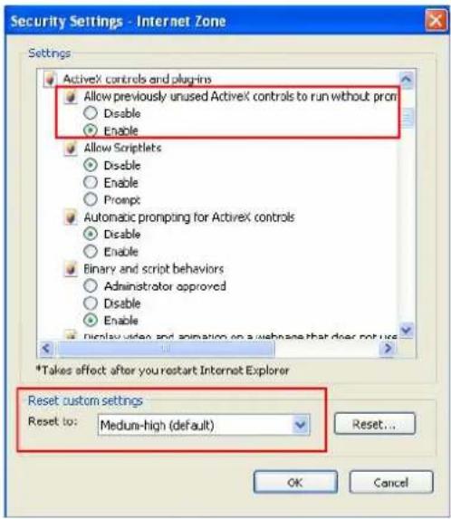
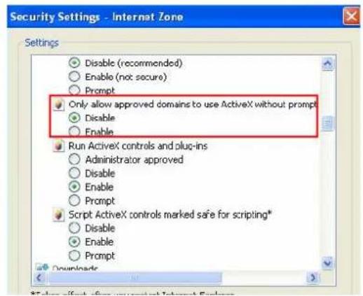
- GeoVision
- Preface
- Contents
- Naming Definition....v
- Options ...... v
- Note for Connecting to GV-System......vi
- Note for Installing Camera Outdoor......vii
- Note for Adjusting GV-Hybrid LPR Camera 20R ......viii
- Chapter 1 Introduction....1
- GV-Hybrid LPR Camera 20R /10R....1
- GV-IP LPR Camera 5R 14
- Chapter 2 Getting Started ....26
- Chapter 3 Guest Mode and Live View Panel....31
- Chapter 4 Administrator Mode ....43
- Chapter 5 Advanced Applications....97
- Chapter 6 DVR Configurations ......107
- Chapter 7 CMS Configurations....118
- Chapter 8 Smart Device Connection....122
- Specifications....132
- Appendix....139
- Naming Definition
- Options
- Note for Connecting to GV-System
- Note for Installing Camera Outdoor
- Note for Adjusting GV-Hybrid LPR Camera 20R
- Chapter 1 Introduction
- GV-Hybrid LPR Camera 20R / 10R
- Features
- System Requirements
- Note:
- Packing List
- Camera Overview
- Device Installation
- Installation Guidelines
- Installing the Camera
- Important:
- Connecting the Camera
- GV-Hybrid LPR Camera 20R
- GV-Hybrid LPR Camera 10R
- Wire Definition
- IR Illuminator
- GV-Hybrid LPR Camera 10R
- GV-IP LPR Camera 5R
- Features
- System Requirements
- Packing List
- Overview
- Device Installation
- Installation Guidelines
- Installing the Camera
- Connecting the Camera
- Adjusting the Angles
- First Shaft
- Second Shaft
- Third Shaft
- Replacing the Silica Gel Bag
- Installing the Sun-Shield Cover
- Chapter 2 Getting Started
- Looking Up the IP Address
- Click the Name or Mac Address column to sort.
- Find the Mac Address of the camera to see its IP address.
- Changing the IP Address
- Accessing Your Surveillance Images
- Configuring the Basics
- Chapter 3 Guest Mode and Live View Panel
- Main Page of Guest Mode
- The Live View Window
- Live View
- The Control Panel of the Live View Window
- Snapshot of a Live Video
- Video Recording
- Picture-in-Picture and Picture-and-Picture View
- Picture-in-Picture View
- Picture-and-Picture View
- Alarm Notification
- Video and Audio Configuration
- Remote Configuration
- Camera Name Display
- Image Enhancement
- Chapter 4 Administrator Mode
- Corresponding Section for Configuration Menu
- Video & Motion
- Video Settings
- [Name]
- [Connection Template]
- [Video Signal Type]
- [Bandwidth Management]
- [GOP Structure and Length]
- [Video Slice Mode]
- [Record Settings]
- [Text Overlay Settings]
- [Watermark Setting]
- [TV Out]
- [LED Control]
- [LPR Setting]
- Motion Detection
- Privacy Mask
- Text Overlay
- Tampering Alarm
- Events & Alerts
- FTP
- [Upload to a FTP server]
- [Act as FTP server]
- Center V2
- [Select schedule time]
- VSM
- Backup Center
- GV-Video Gateway / GV-Recording Server
- ViewLog
- RTSP
- Monitoring
- GV-Hybrid LPR Camera 20R / 10R
- GV-IP LPR Camera 5R
- [Camera Status Icon]
- Recording Schedule
- Recording Schedule Settings
- Network
- LAN Configuration
- [LAN Configuration]
- Advanced TCP/IP
- [Dynamic DNS Server Settings]
- To enable the DDNS function:
- [HTTP Port Settings]
- [HTTPS Settings]
- [Camera Streaming Port Settings]
- [UPnP Settings]
- [QoS Settings]
- [Network Connection Check Settings]
- IP Filtering
- SNMP Settings
- Management
- Date and Time Settings
- GPS Maps Settings
- Click Open. A warning message appears.
- Storage Settings
- [Storage Settings]
- [Disk Information]
- [Partition Information]
- User Account
- Log Information
- System Log
- Tools
- Language
- Chapter 5 Advanced Applications
- Upgrading System Firmware
- Important Notes before You Start
- Using the Web Interface
- Using the GV-IP Device Utility
- Backing Up and Restoring Settings
- To back up the settings
- To restore the settings
- Restoring to Factory Default Settings
- Using the Web Interface
- Directly on the Camera
- Verifying Watermark
- Accessing AVI Files
- Running Watermark Proof
- The Watermark Proof Window
- Chapter 6 DVR Configurations
- Setting Up IP Cameras
- Customizing Camera Settings
- Remote Monitoring with Multi View
- Connecting to GV-Hybrid LPR Camera 20R / 10R / GV-IP LPR Camera 5R
- Remote Monitoring with E-Map
- Creating an E-Map for the Camera
- of Cameras: 1
- of Modules: 0
- of Inputs: 1
- of Outputs: 1
- Connecting to the Camera
- Chapter 7 CMS Configurations
- Center V2
- VSM
- Dispatch Server
- Chapter 8 Smart Device Connection
- Android
- Connecting to the Camera
- Accessing Live View
- Apple
- Connecting to the Camera
- Accessing Live View
- Specifications
- Appendix
- The CGI Command
- RTSP Protocol Support
- Settings for Internet Explorer 8 or later
Brand : Geovision
Model : GV-HYBRIDLPR
Category : Security Camera