C-VS-1300-TBZ - Car kit Havis - Free user manual and instructions
Find the device manual for free C-VS-1300-TBZ Havis in PDF.


| Product Type | Vehicle Console Kit |
| Brand | Havis |
| Model | C-VS-1300-TBZ |
| Compatible Vehicles | 2002-2009 Chevrolet Trailblazer |
| Console Material | High-strength polymer and steel bracket |
| Mounting Location | Between front seats, floor-mounted |
| Installation Method | Bolt-on using OEM seat studs and brackets |
| Required Tools | Phillips screwdriver, T-15 and T-20 Torx drivers, 7/16" wrench, ratchet wrench, 7/16" and 15mm sockets, jig saw or plastic cutting tool, eye goggles |
| Included Hardware - Console Body | 1x C-VS-1300-TBZ-H |
| Included Hardware - Brackets | 1x bail bracket (C-B1), 1x rear hump bracket set (C-B27), 2x side L brackets (CM93594) |
| Included Hardware - Plates & Kits | 1x duct block off plate (CM001516), 1x console hardware kit (C-HK), 1x Torx screw kit (C-HK-1), 1x #10x1/2 PPHSMS (GSM33194) |
| Special Notes | Disconnect battery before installation; check for obstructions before drilling; use only provided hardware |
| Modifications Required | Cutting of rear console section required |
| Weight Capacity | Not specified, typical up to 20 lbs |
| Warranty | Refer to manufacturer |
| Manufacturer | Havis, Inc. |
Frequently Asked Questions - C-VS-1300-TBZ Havis
User questions about C-VS-1300-TBZ Havis
0 question about this device. Answer the ones you know or ask your own.
Ask a new question about this device
Download the instructions for your Car kit in PDF format for free! Find your manual C-VS-1300-TBZ - Havis and take your electronic device back in hand. On this page are published all the documents necessary for the use of your device. C-VS-1300-TBZ by Havis.
USER MANUAL C-VS-1300-TBZ Havis
INSTALL INSTRUCTIONS C-VS-1300-TBZ VEHICLE SPECIFIC CONSOLE 2002-2009 CHEVROLET TRAILBLAZER
TOOLS REQUIRED:
□ Phillips screwdriver
□ T-15 Torx driver
□ T-20 Torx driver
□ 7/16 wrench
□ Ratchet wrench
□ 7/16" socket
□ 15mm socket
□ Jig Saw or plastic cutting tool
□ Eye goggles
HARDWARE:
QTY DESCRIPTION PART #
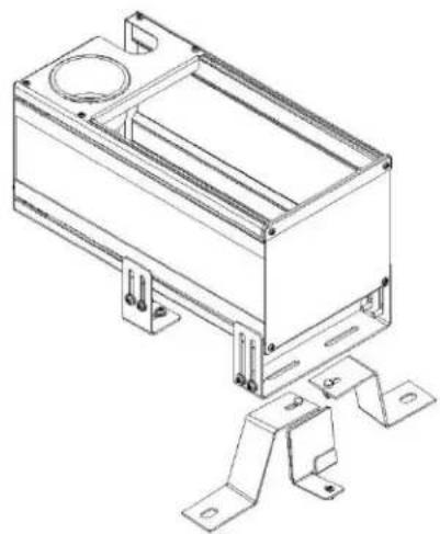
1 Trailblazer vehicle specific console C-VS-1300-TBZ-H
1 Bail bracket C-B1
1 Rear hump bracket set C-B27
1 Duct block off plate CM001516
2 Side "L" brackets CM93594
1 Console hardware kit C-HK
1 Torx screw kit C-HK-1
1 #10x1/2 PPHSMS (Block off plate screw) GSM33194
Always!
Read all instructions before installing any Havis, Inc. products.
➢ Disconnect the vehicle battery. Removing seat bolts on some vehicles may give the vehicles computer a false reading, causing a warning light on the instrument cluster. This requires the vehicles' computer to be reset with a vehicle diagnostics tool.
➢ Check for obstructions (Wire, brake lines, fuel tank, etc.) before drilling any holes!
➢ Use only hardware provided with install kit.
natural_image
Technical line drawing of a rectangular electronic enclosure with mounting brackets and mounting holes (no text or symbols)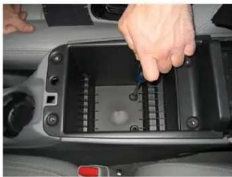
natural_image
Close-up of a hand inserting a component into a black plastic control box (no visible text or symbols)Remove six phillips screws that hold inner storage pocket. Remove storage pocket and arm rest assembly.
natural_image
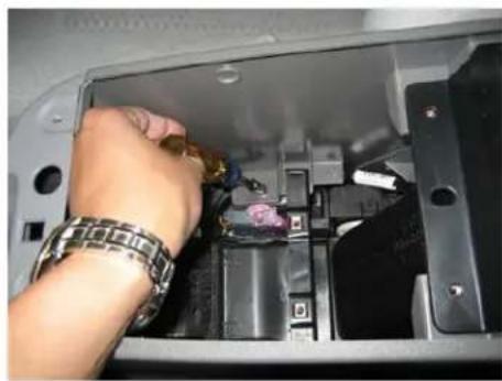
Close-up of a hand inserting a component into an automotive battery pack (no visible text or symbols)Remove main console screws.
natural_image
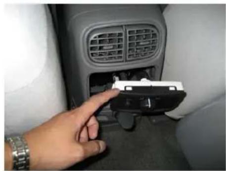
Hand inserting a small electronic device into a car air vent (no visible text or symbols)Unplug wires for rear controls.
natural_image
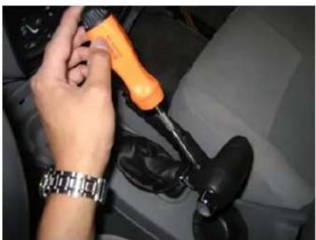
Close-up of a hand using an orange screwdriver to adjust the gear shift lever inside a car (no visible text or symbols)Remove shift lever "T" knob. (T15 Torx)
natural_image
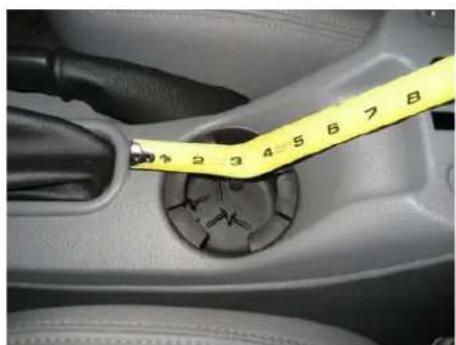
Close-up of a car headset with a yellow measuring tape showing measurement markings (no text or symbols on the object itself)Measure approximately 3 12 " back from shift lever boot.
natural_image
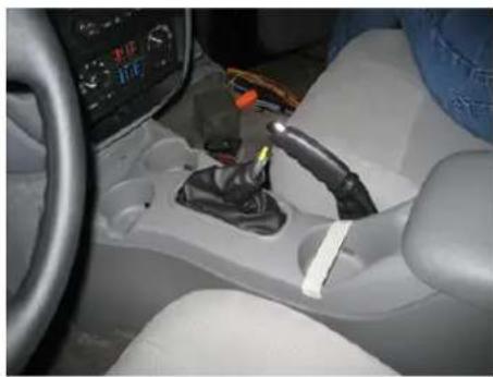
Interior view of a car showing a white car gear shift lever and dashboard (no visible text or symbols)Mark Measurement with tape.
natural_image
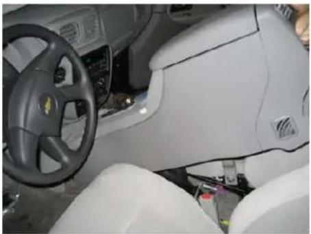
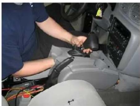
Interior view of a car dashboard and steering wheel (no visible text or symbols)Position shift lever in drive or further back. Remove entire console assembly.
natural_image
Person working inside a car gear shift lever, no visible text or symbolsNote: In order to remove console, you must reach up inside the shifter boot and disconnect the traction control plug.
natural_image
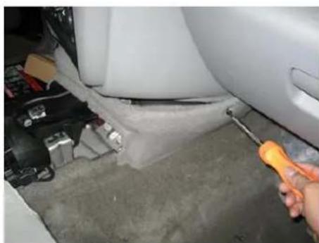
Close-up of a car interior showing a hand using a screwdriver to adjust the seat area (no visible text or symbols)Remove front trim to aid in running additional wiring.
natural_image
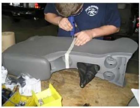
Person adjusting a gray car seat with a black handle, surrounded by tools and materials (no visible text or symbols)Extend cut line on console sides. Carefully cut off back console section. (Jig saw, Air saw, Dremel or Air drill)
natural_image
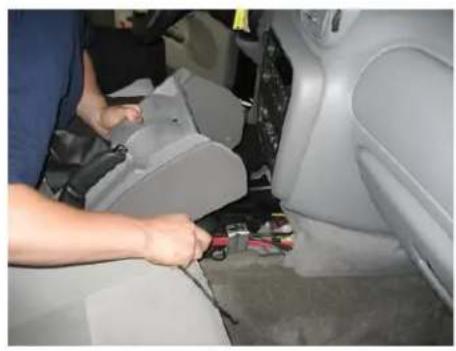
Person adjusting a car seatbelt inside a vehicle (no visible text or symbols)Carefully reinstall front console section. (Reattach Traction Control Plug)
natural_image
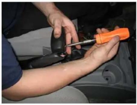
Person using a screwdriver to adjust or repair a car's seatbelt (no visible text or symbols)Reattach shift lever "T" handle.
natural_image
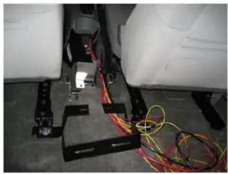
Interior view of a vehicle chassis with wiring and sensors, no visible text or symbolsRemove inboard rear seat nuts. (15mm) Place new rear hump brackets on seat studs under seat brackets.
natural_image
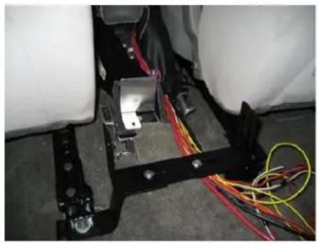
Interior view of a vehicle's seat assembly with colored wires and wiring (no visible text or symbols)Attach bail bracket onto rear hump brackets with 14 x 34 bolts. Note: You may need to bend hump brackets slightly forward.
natural_image
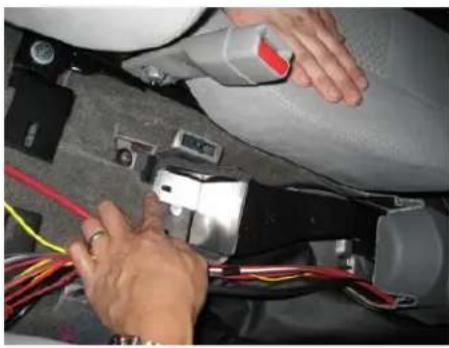
Close-up of hands installing or adjusting a mechanical component with wires and a tool (no visible text or symbols)Place duct block off plate in duct opening and screw down with #10 x 12 " sheet metal screw.
natural_image
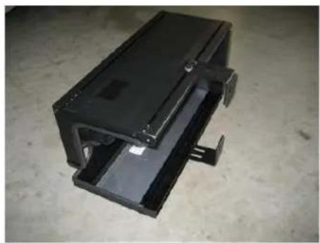
Metallic mechanical component with internal channels and mounting brackets, placed on a concrete floor (no text or symbols visible)Attach "L" mount brackets to new console lower side tracks with 14 × 12 bolts and washers. **Leave loose to aid in positioning.
natural_image
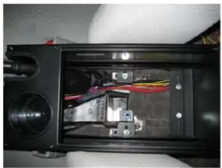
Interior view of a black electronic device showing internal wiring and components (no visible text or symbols)Place new console between seats and position "L" mount brackets onto OEM bracket. Attach with 1/4" x 3/4" bolts.
natural_image
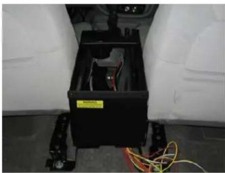
Interior view of a vehicle showing a black battery box with visible wiring and a yellow warning label, placed on wheels (no text or symbols)Position console housing as desired and tighten all mount hardware. **Check shift lever in rear position.
natural_image
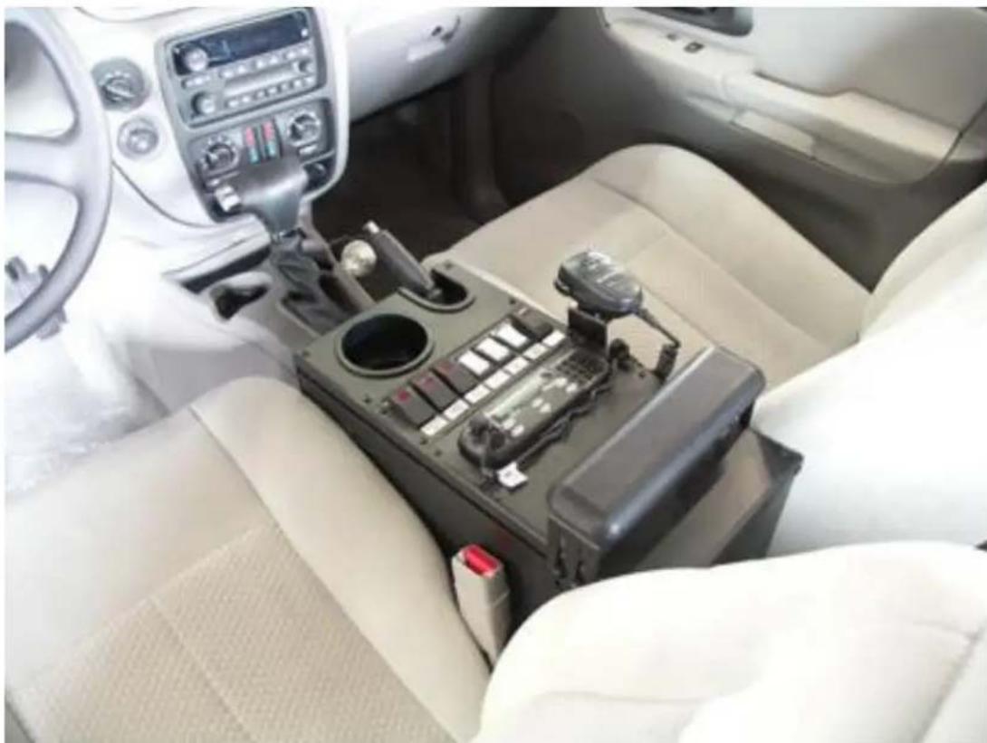
Interior view of a car showing the driver's seat, dashboard, and control panel (no visible text or symbols)Finish wiring and complete installation
Brand : Havis
Model : C-VS-1300-TBZ
Category : Car kit