
DME64NV1 - Audio signal processor YAMAHA - Free user manual and instructions
Find the device manual for free DME64NV1 YAMAHA in PDF.

| Product Type | Audio Signal Processor (Digital Mixing Engine) |
| Brand | YAMAHA |
| Model | DME64N (DME64NV1) |
| Maximum Audio Capacity | 64 channels (with 4 I/O cards, 16 channels per card) |
| Number of I/O Slots | 4 slots for mini-YGDAI cards |
| Front Connectors | USB port, LED indicators (clock, network, MIDI, master, scene), display, navigation keys, wheel, headphone jack, SCENE/HOME/UTILITY/LEVEL/MUTE/MONITOR buttons, POWER switch |
| Rear Connectors | AC IN, ground screw, GPI (16 inputs/outputs), MIDI IN/OUT/THRU, WORD CLOCK IN/OUT, NETWORK (Ethernet), REMOTE (RS-232C), CASCADE IN/OUT (D-SUB 68 pins), 4 I/O slots |
| Main Functions | Configurable digital mixing, DSP processing (equalizers, compressors, reverb, delay, effects), matrix routing, scene management (up to 999), user parameters (24 per zone), control via DME Designer, CobraNet support (with MY16-C card), cascade up to 32 audio and clock channels, external clock synchronization |
| Power Supply | Mains, voltage according to nameplate (e.g., 100-240 V AC, 50/60 Hz) |
| Dimensions (W × H × D) | 480 mm × 88 mm × 400 mm (approximate, 2U rack format) |
| Maintenance and Cleaning | Use a dry, soft cloth. Disconnect before cleaning. Do not use solvents. |
| Safety | Do not open the device (no user-serviceable parts). Use only the specified voltage. Mandatory grounding. Do not expose to moisture. Disconnect during thunderstorms or extended periods of non-use. |
| Spare Parts and Repairability | Internal lithium battery for memory backup (replacement by a Yamaha authorized technician). No other user-repairable parts. Contact Yamaha service for any intervention. |
| Supplied Accessories | Power cable, cable clamp, Euroblock connectors (16P × 2, 8P × 4), CD-ROM (DME Designer, drivers) |
| Options | mini-YGDAI I/O cards (MY16-C, MY8-AE, etc.), control panels ICP1, CP4SW, CP4SF, CP1SF |
Frequently Asked Questions - DME64NV1 YAMAHA
User questions about DME64NV1 YAMAHA
0 question about this device. Answer the ones you know or ask your own.
Ask a new question about this device
Download the instructions for your Audio signal processor in PDF format for free! Find your manual DME64NV1 - YAMAHA and take your electronic device back in hand. On this page are published all the documents necessary for the use of your device. DME64NV1 by YAMAHA.
USER MANUAL DME64NV1 YAMAHA
DIGITAL MIXING ENGINE
DME64N / DME24N
Owner's Manual
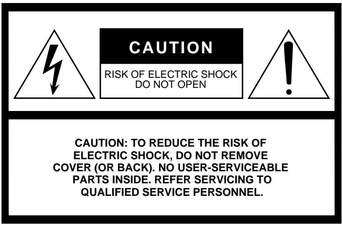
The above warning is located on the top of the unit.
Explanation of Graphical Symbols
The lightning flash with arrowhead symbol within an equilateral triangle is intended to alert the user to the presence of uninsulated "dangerous voltage" within the product's enclosure that may be of sufficient magnitude to constitute a risk of electric shock to persons.

The exclamation point within an equilateral triangle is intended to alert the user to the presence of important operating and maintenance (servicing) instructions in the literature accompanying the product.
IMPORTANT SAFETY INSTRUCTIONS
1 Read these instructions.
2 Keep these instructions.
3 Heed all warnings.
4 Follow all instructions.
5 Do not use this apparatus near water.
6 Clean only with dry cloth.
7 Do not block any ventilation openings. Install in accordance with the manufacturer's instructions.
8 Do not install near any heat sources such as radiators, heat registers, stoves, or other apparatus (including amplifiers) that produce heat.
9 Do not defeat the safety purpose of the polarized or grounding-type plug. A polarized plug has two blades with one wider than the other. A grounding type plug has two blades and a third grounding prong. The wide blade or the third prong are provided for your safety. If the provided plug does not fit into your outlet, consult an electrician for replacement of the obsolete outlet.
10 Protect the power cord from being walked on or pinched particularly at plugs, convenience receptacles, and the point where they exit from the apparatus.
WARNING
TO REDUCE THE RISK OF FIRE OR ELECTRIC SHOCK, DO NOT EXPOSE THIS APPARATUS TO RAIN OR MOISTURE.
11 Only use attachments/accessories specified by the manufacturer.
12 Use only with the cart, stand, tripod, bracket, or table specified by the manufacturer, or sold with the apparatus. When a cart is used, use caution when moving the cart/ apparatus combination to avoid injury from tip-over.
13 Unplug this apparatus during lightning storms or when unused for long periods of time.
14 Refer all servicing to qualified service personnel. Servicing is required when the apparatus has been damaged in any way, such as power-supply cord or plug is damaged, liquid has been spilled or objects have fallen into the apparatus, the apparatus has been exposed to rain or moisture, does not operate normally, or has been dropped.

FCC INFORMATION (U.S.A.)
1. IMPORTANT NOTICE: DO NOT MODIFY THIS UNIT!
This product, when installed as indicated in the instructions contained in this manual, meets FCC requirements. Modifications not expressly approved by Yamaha may void your authority, granted by the FCC, to use the product.
- IMPORTANT: When connecting this product to accessories and/ or another product use only high quality shielded cables. Cable/s supplied with this product MUST be used. Follow all installation instructions. Failure to follow instructions could void your FCC authorization to use this product in the USA.
- NOTE: This product has been tested and found to comply with the requirements listed in FCC Regulations, Part 15 for Class "B" digital devices. Compliance with these requirements provides a reasonable level of assurance that your use of this product in a residential environment will not result in harmful interference with other electronic devices. This equipment generates/uses radio frequencies and, if not installed and used according to the instructions found in the users manual, may cause interference harmful to the operation of other electronic devices. Compliance with FCC regulations does
not guarantee that interference will not occur in all installations. If this product is found to be the source of interference, which can be determined by turning the unit "OFF" and "ON", please try to eliminate the problem by using one of the following measures:
Relocate either this product or the device that is being affected by the interference.
Utilize power outlets that are on different branch (circuit breaker or fuse) circuits or install AC line filter/s.
In the case of radio or TV interference, relocate/reorient the antenna. If the antenna lead-in is 300 ohm ribbon lead, change the lead-in to co-axial type cable.
If these corrective measures do not produce satisfactory results, please contact the local retailer authorized to distribute this type of product. If you can not locate the appropriate retailer, please contact Yamaha Corporation of America, Electronic Service Division, 6600 Orangethorpe Ave, Buena Park, CA90620
The above statements apply ONLY to those products distributed by Yamaha Corporation of America or its subsidiaries.
- This applies only to products distributed by YAMAHA CORPORATION OF AMERICA.
(class B)
IMPORTANT NOTICE FOR THE UNITED KINGDOM
Connecting the Plug and Cord
WARNING: THIS APPARATUS MUST BE EARTHED
IMPORTANT. The wires in this mains lead are coloured in accordance with the following code:
GREEN- AND- YELLOW : EARTH
BLUE : NEUTRAL
BROWN : LIVE
As the colours of the wires in the mains lead of this apparatus may not correspond with the coloured markings identifying the terminals in your plug proceed as follows:
The wire which is coloured GREEN-and-YELLOW must be connected to the terminal in the plug which is marked by the letter E or by the safety earth symbol or colored GREEN or GREEN-and-YELLOW.
The wire which is coloured BLUE must be connected to the terminal which is marked with the letter N or coloured BLACK.
The wire which is coloured BROWN must be connected to the terminal which is marked with the letter L or coloured RED.
This applies only to products distributed by Yamaha-Kemble Music (U.K.) Ltd. (3 wires)
NEDERLAND/THE NETHERLANDS
- For the removal of the battery at the moment of the disposal at the end of the service life please consult your retailer or Yamaha Service Center as follows:
Yamaha Music Nederland Service Center
Address : Kanaalweg 18-G, 3526 KL UTRECHT
Tel : 030-2828425
- Gooi de batterij Niet weg, maar lever hem in als KCA.
- Do not throw away the battery. Instead, hand it in as small chemical waste.
(lithium disposal)
ADVARSELI!
- Please keep this manual in a safe place for future reference.

WARNING
Always follow the basic precautions listed below to avoid the possibility of serious injury or even death from electrical shock, short-circuiting, damages, fire or other hazards. These precautions include, but are not limited to, the following:
Power supply/Power cord
- Only use the voltage specified as correct for the device. The required voltage is printed on the name plate of the device.
- Use only the specified power cord.
- Do not place the power cord near heat sources such as heaters or radiators, and do not excessively bend or otherwise damage the cord, place heavy objects on it, or place it in a position where anyone could walk on, trip over, or roll anything over it.
Do not open
- Do not open the device or attempt to disassemble the internal parts or modify them in any way. The device contains no user-serviceable parts. If it should appear to be malfunctioning, discontinue use immediately and have it inspected by qualified Yamaha service personnel.
Water warning
- Do not expose the device to rain, use it near water or in damp or wet conditions, or place containers on it containing liquids which might spill into any openings.
- Never insert or remove an electric plug with wet hands.
If you notice any abnormality
- If the power cord or plug becomes frayed or damaged, or if there is a sudden loss of sound during use of the device, or if any unusual smells or smoke should appear to be caused by it, immediately turn off the power switch, disconnect the electric plug from the outlet, and have the device inspected by qualified Yamaha service personnel.
- If this device should be dropped or damaged, immediately turn off the power switch, disconnect the electric plug from the outlet, and have the device inspected by qualified Yamaha service personnel.

CAUTION
Always follow the basic precautions listed below to avoid the possibility of physical injury to you or others, or damage to the device or other property. These precautions include, but are not limited to, the following:
Power supply/Power cord
- Remove the electric plug from the outlet when the device is not to be used for extended periods of time, or during electrical storms.
- When removing the electric plug from the device or an outlet, always hold the plug itself and not the cord. Pulling by the cord can damage it.
Location
- Before moving the device, remove all connected cables.
- Avoid setting all equalizer controls and faders to their maximum. Depending on the condition of the connected devices, doing so may cause feedback and may damage the speakers.
- Do not expose the device to excessive dust or vibrations, or extreme cold or heat (such as in direct sunlight, near a heater, or in a car during the day) to prevent the possibility of panel disfiguration or damage to the internal components.
- Do not place the device in an unstable position where it might accidentally fall over.
- Do not block the vents. This device has ventilation holes at the front and rear to prevent the internal temperature from rising too high. In particular, do not place the device on its side or upside down, or place it in any poorly-ventilated location, such as a bookcase or closet.
- Do not use the device in the vicinity of a TV, radio, stereo equipment, mobile phone, or other electric devices. Otherwise, the device, TV, or radio may generate noise.
Connections
- Before connecting the device to other devices, turn off the power for all devices. Before turning the power on or off for all devices, set all volume levels to minimum.
- Be sure to connect to a properly grounded power source. A ground screw terminal is provided on the rear panel for safely grounding the device and preventing electrical shock.
Maintenance
- Remove the power plug from the AC outlet when cleaning the device.
Handling caution
- Do not insert your fingers or hand in any gaps or openings on the device (vents, ports, etc.).
- Avoid inserting or dropping foreign objects (paper, plastic, metal, etc.) into any gaps or openings on the device (vents, ports, etc.) If this happens, turn off the power immediately and unplug the power cord from the AC outlet. Then have the device inspected by qualified Yamaha service personnel.
- Do not use the device or headphones for a long period of time at a high or uncomfortable volume level, since this can cause permanent hearing loss. If you experience any hearing loss or ringing in the ears, consult a physician.
- Do not rest your weight on the device or place heavy objects on it, and avoid use excessive force on the buttons, switches or connectors.
Backup battery
- This device has a built-in backup battery. When you unplug the power cord from the AC outlet, the internal SRAM data is retained. However, if the backup battery fully discharges, this data will be lost. When the backup battery is running low, the Display indicates "Low Battery" or "No Battery." In this case, immediately save the data to an external devices such as a computer, then have qualified Yamaha service personnel replace the backup battery.
Yamaha cannot be held responsible for damage caused by improper use or modifications to the device, or data that is lost or destroyed.
Always turn the power off when the device is not in use.
The performance of components with moving contacts, such as switches, volume controls, and connectors, deteriorates over time. Consult qualified Yamaha service personnel about replacing defective components.
The illustrations in this document are for instructional purposes, and may appear somewhat different from the actual equipment.
- The bitmap fonts used in this device have been provided by and are the property of Ricoh Co., Ltd.
CobraNet and Peak Audio are trademarks of Cirrus Logic, Inc.
- Ethernet is a trademark of Xerox Corporation.
- All other trademarks are the property of their respective holders and are hereby acknowledged.
Foreword
Thank you for choosing a Yamaha DME64N/24N Digital Mixing Engine.
Using the supplied DME Designer software, the DME64N and DME24N can be easily configured to handle a wide range of audio processing applications – institutional audio installations, sub-mixing, speaker system control, matrix and routing, multi-effect processing, and much more.
In order to take full advantage of the features and performance provided by the DME64N/24N, we urge you to read this owner's manual thoroughly before use, and keep it in a safe place for future reference.
The Yamaha Pro Audio web site is at: http://www.yamahaaproaudio.com/
Contents
About the Documentation. 8
Supplied Accessories 8
DME64N and DME24N I/O Configuration . . 8
Options 8
DME64N/24N Audio System Overview 9
The DME64N/24N Configurable Digital Mixing
Engine 9
System Examples. 10
DME64N/24N Audio System Network . 13
DME64N/24N Audio System Control . 14
DME Designer 15
The Controls and Connectors 16
Front Panel 16
Rear Panel 18
Preparation 20
Setup Procedure. 20
I/O Card Installation. 22
Compatible I/O Cards 22
I/O Card Installation Procedure 23
Connection 24
Signal Types 24
USB Connection 26
Ethernet Connection ([NETWORK] Connector) ..... 27
MIDI Connection 30
GPI Connection 31
CASCADE Connection (DME64N only) 32
WORD CLOCK Connection 33
REMOTE Connection. 34
Analog Audio Connection ([IN] and [OUT] Connectors)
(DME24N only). 35
I/O Slots. 37
Panel Operation and Displays 38
The Panel Buttons and Displays 38
Main Display. 39
Parameter Edit Displays. 40
Editing User Defined Parameters 42
Mute Switching 42
Output Level Control. 42
Scene Recall 43
SceneStore. 43
Monitoring. 44
Spectrum Display. 45
Level Meter Display. 46
Utility Displays 47
Items accessible via the Utility display. 47
Utility Display Operation 48
Info Page. 48
Network Settings (Net) Page. 48
Display Setup (Disp) Page 49
Security Setup (Lock) Page 50
Miscellaneous Setup (Misc) Page 51
WordClock Setup (WCLK) Page. 51
Slot Information (Slot) Page 52
MIDI Setup (MIDI) Page. 52
GPI Setup (GPI) Page. 53
Head Amplifier Setup (HA) Page 54
Cascade Setup (CASCAD) Page 55
Appendix 56
Options 56
ICP1. 56
CP4SW, CP4SF, and CP1SF 59
Error Messages. 61
Troubleshooting 63
Specifications. 65
Control I/O 65
Connector Pin Assign 66
Dimensions 68
MIDI Data Format 69
Glossary. 74
Index 76
About the Documentation
The following manuals are provided with the DME64N/24N.
DME64N/24N Owner's Manual (This document)
This document covers the specifications, installation, and operation of the DME64N/24N.
DME Designer Installation Guide
This document covers the installation of the DME Designer software application and related drivers (USB-MIDI driver, DME-N Network driver) on a computer, computer setup, and connection of the computer to the DME64N/24N.
DME Designer Owner's Manual (PDF file)
The DME Designer Manual describes operation of the DME Designer software as well as the functions of the individual modules that can be used.
Supplied Accessories
- DME64N/24N Owner's Manual (This document)
- DME Designer Installation Guide
CD-ROM -
AC power cord
-
AC plug clamp
Euroblock plug (16P) x 2 - Euroblock plug (8P) x 4 (DME64N only)
Euroblock plug (3P) x 16 (DME24N only)
DME64N and DME24N I/O Configuration
The DME64N has four I/O card slots, while the DME24N has one I/O card slot and eight channels of built-in analog audio I/O.
A single I/O card can handle up to 16 channels of audio I/O, so the DME64N can handle a maximum of 64 audio I/O channels. The DME24N can handle up to 24 audio I/O channels.
The DME64N has approximately double the DSP processing power of the DME24N.
Options
Control Panels
- ICP1 Intelligent Control Panel
- CP4SW Control Panel
- CP4SF Control Panel
- CP1SF Control Panel
NOTE
Refer to the appendix on page 56 for information about the control panels.
mini-YGDAI (Yamaha General Digital Audio Interface) I/O Cards
- MY16-C, MY16-AT, MY16-AE, MY16-TD, and others.
NOTE
Refer to I/O Card Installation on page 22 for information on I/O card installation and the types of I/O cards that can be used.
DME64N/24N Audio System Overview
The DME64N/24N Configurable Digital Mixing Engine
In addition to basic mixing and matrix output functions, the DME64N/24N includes a full range of processing modules – equalizers, compressors, reverb and delay, effects, etc. – that can be patched together using the DME Designer software to support just about any audio system you need. It can serve as the central audio processing and routing unit in an installed system, or it can serve to augment the functionality of an existing or touring system. A few examples are provided below:
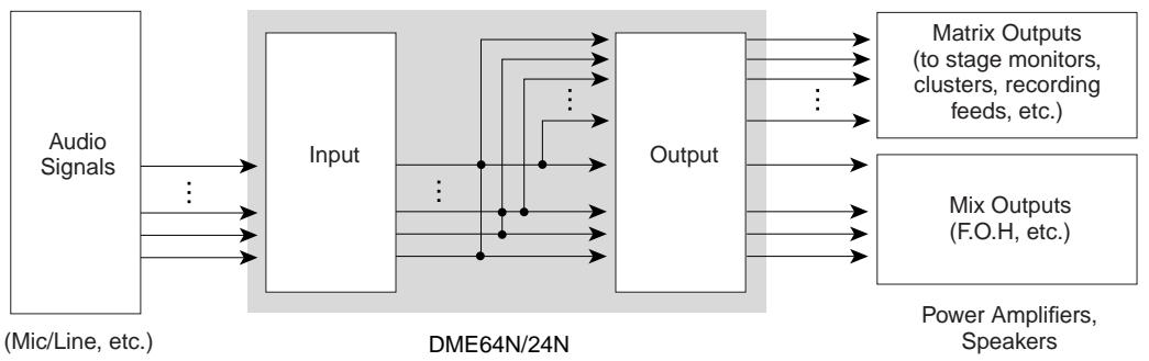
Matrix Output Expansion
Particularly in concert situations there always seems to be a need for more feeds and outputs. The DME64N/24N can function as an extremely versatile output matrixROUTer system that can be easily reconfigured to meet changing system requirements.
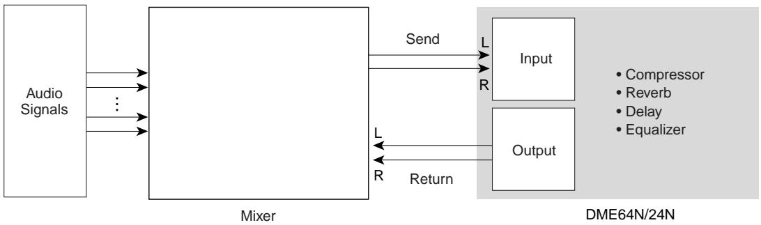
Outboard Signal Processing
A single DME64N/24N can replace racks of standard outboard processing and effects gear.
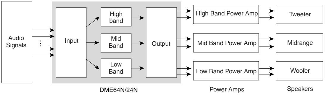
Output Processor
Multi-band output processing is just one of the many output processing functions the DME64N/24N could be applied to. A single DME64N can handle up to 64 channels, while a DME24N can handle up to 24 channels, for extraordinary capacity and versatility.
System Examples
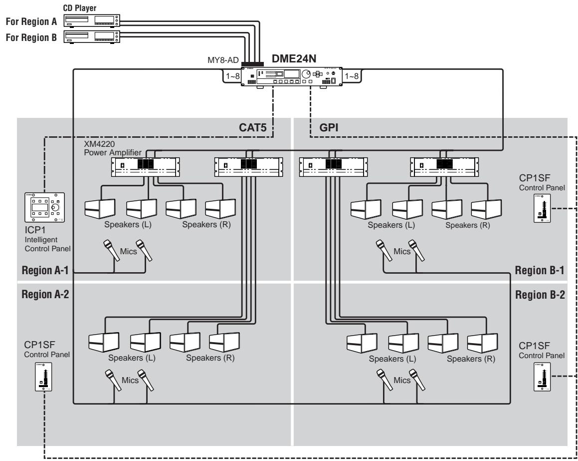
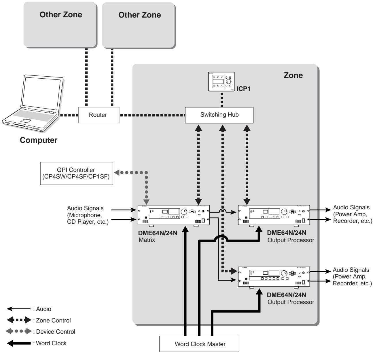
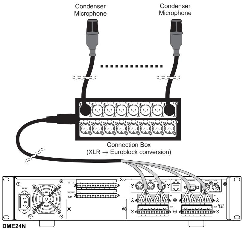
Single DME24N: A Meeting Room Installation
Here's an example of a single DME24N used to control the sound in four partitionable regions. The built-in microphone preamplifiers and A/D converters allow direct connection of up to 8 microphone inputs, while the 8 analog outputs can directly feed four stereo power amplifiers. Scenes can be set up to handle any of the possible partition configurations, allowing background music and microphone sources to be handled as required by each configuration.
In this example an ICP1 Intelligent Control Panel is installed in one region to allow scene recall and parameter control. Other regions have a 1-fader 1-switch CP1SF control panels to allow users to adjust microphone and background music levels.
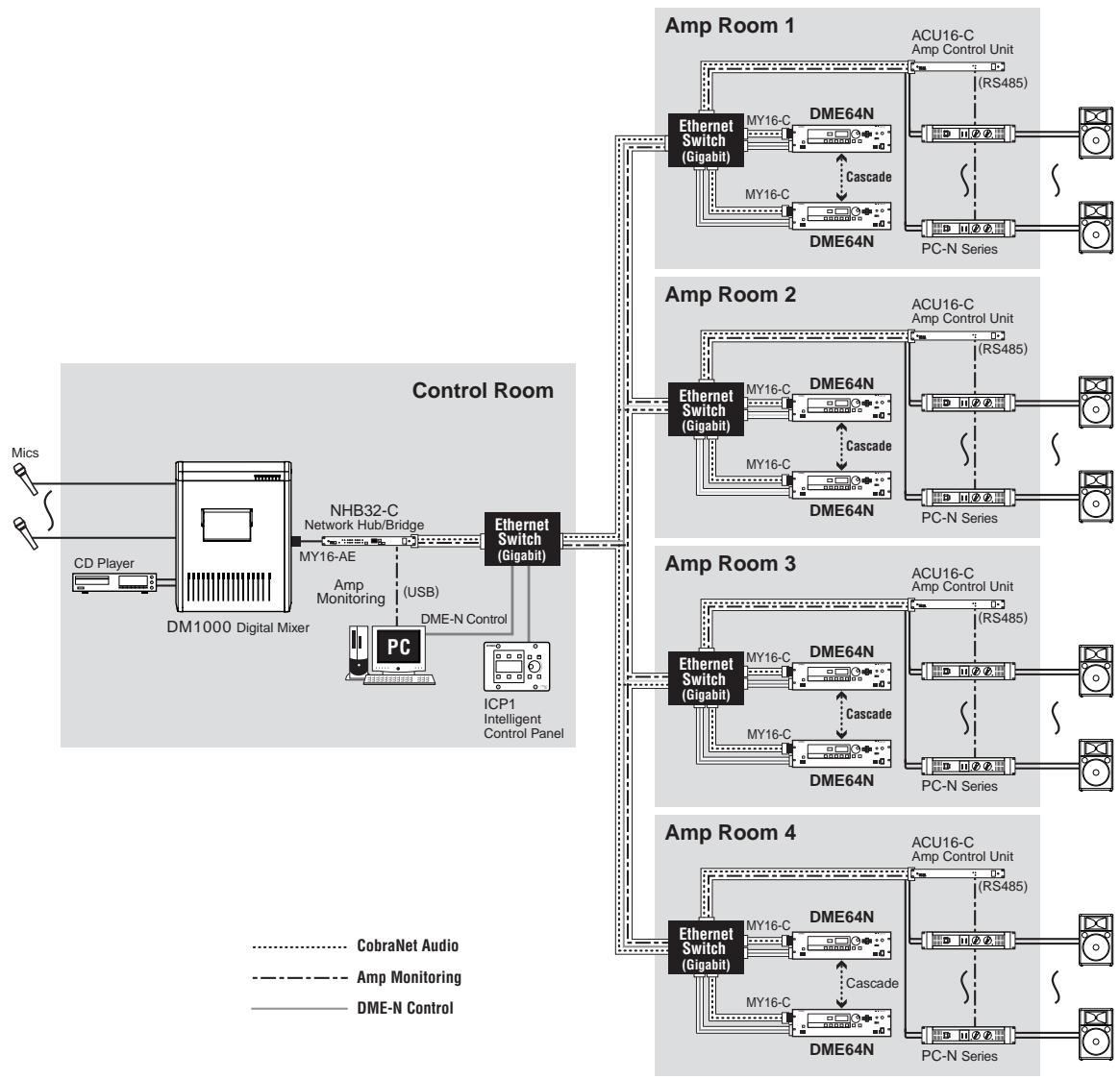
Multiple DME64N: Large Stadium Or Multi-purpose Hall System
In this system live audio from microphones is mixed with background music and other sources in the central control room using a Yamaha DM1000 digital mixing console. A DM1000 equipped with an MY16-AE digital I/O card and an NHB32-C network hub bridge can feed the control room output to the system's DME64N units over distances of up to 2 kilometers via multimode optical fiber cables. The control room also houses the system-control computer running the DME Designer application software, and an ICP1 Intelligent Control Panel for general DME unit control. The audio and control signals from the control room are distributed to four amp rooms (zones) via the CobraNet Ethernet cable. One or more DME64N units in each amp room handles signal routing and output processing (equalization, limiting, crossover) and the resultant digital output is converted to analog audio and fed to the power amplifiers via ACU16-C Amplifier Control Units. Scene switching to accommodate a variety of spectator/audience seating areas for different types of events can be handled from both the control-room PC and ICP1 control panel.
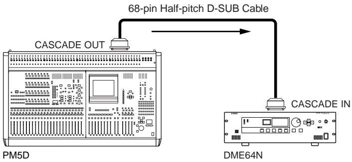
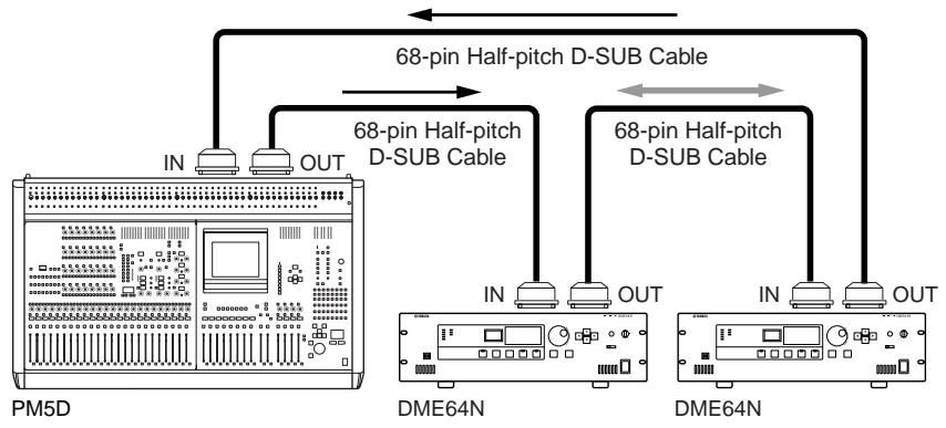
Single DME64N: Sound Reinforcement
For live sound reinforcement applications a DME64N can be connected to a Yamaha PM5D digital mixing console, for example, to provide significantly expanded processing power. In this type of application the DME64N could be used to provide up to an additional 64 matrix outs as well as output processing such as GEQs, level controls, crossovers, delays, and more. The DME-to-conSOLE connection can be made either the cascade connector.
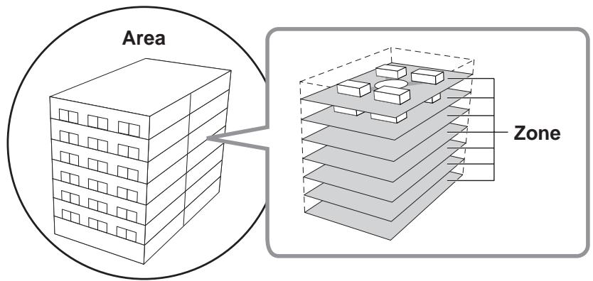
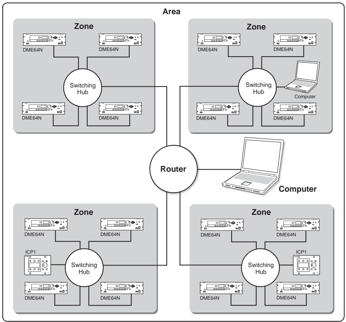
DME64N/24N Audio System Network
To facilitate understanding and conceptualizing an overall DME64N/24N system, the terms "area" and "zone" are applied. The entire area serviced by the system is the "area," while audio processing divisions within the area are "zones." A single computer can be used to control the entire area as well as individual zones in a DME64N/24N audio system.
Up to 16 DME64N/24N units can operate in any one zone. DME64N/24N units in each zone are interconnected and function as a single system.
Each zone always includes one DME64N/24N, which functions as the “zone master” and controls all other DME64N/24N and ICP1 units (zone slaves) in the same zone. If a computer is connected to the zone master, the computer can be used to control all devices in the zones.
DME64N/24N Audio System Control
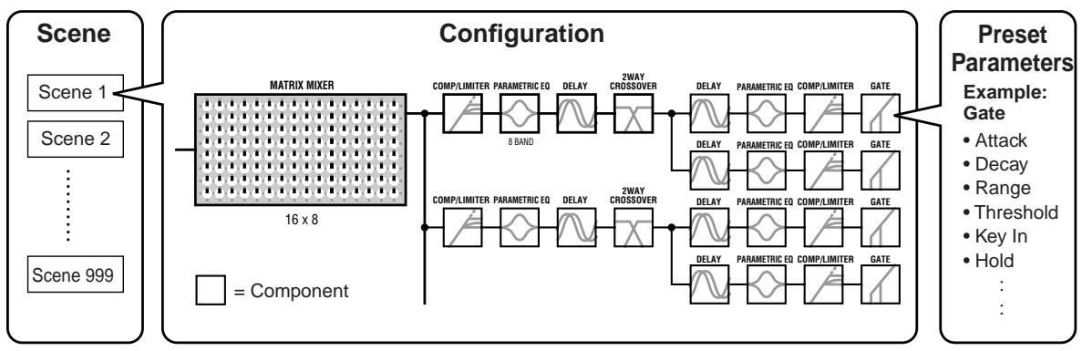
To facilitate understanding and controlling an overall DME64N/24N system, the terms "component," "parameter," "scene," and "user-defined parameter" are applied.
Components & Parameters
The individual audio modules (equalizers, compressors, etc.) are called "components." Head amplifier modules are also prepared as components. Changing the parameters of components enables control over the operation of the components.
Configurations
A "configuration" is a complete set of components for constructing an audio system. Each configuration determines the audio function(s) of the corresponding DME64N/24N unit. All parameter sets included with each component are called "preset parameters." One DME64N/24N unit has a number of configurations, and a configuration has a number of preset parameters.
User-defined Parameters
By assigning a parameter to a user-defined parameter, the user-defined parameter can be controlled from the panels of the DME64N/24N and ICP1, or other controllers connected via MIDI or GPI. Multiple parameters assigned to a single user-defined parameter will be controlled simultaneously. Up to 24 user-defined parameters can be used in a zone.
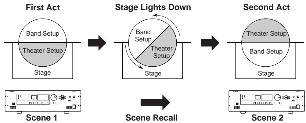
Scenes
A combination of all configuration and preset parameter combinations is called a "scene." A scene determines the audio effect(s) in the zone. Scenes can be recalled from the panels of the DME64N/24N and ICP1, other controllers connected via MIDI or GPI, or computer control. Up to 999 scenes can be stored for each zone.
NOTE
Slight delays might be experienced when switching scenes or editing user-defined parameters, depending on the network condition.
Scene Structure
Scene Change
DME Designer
The DME Designer software application, supplied with the DME64N/24N, can be used to create configurations as well as control the entire area.
A DME64N/24N network system cannot be set up entirely from the DME64N/24N alone. Configurations and scene data must be created on a computer running the DME Designer application, and then transferred from the computer to the DME64N/24N. The DME Designer can also be used to determine how external controllers will control DME64N/24N parameters.
Refer to the DME Designer Installation Guide for detailed information on connecting a computer to the DME64N/24N and installing the required software drivers.
Refer to the DME Designer Owner's Manual for setup and operation instructions. The PDF manual will automatically be copied to the computer when the DME Designer application is installed.

The Controls and Connectors
Front Panel
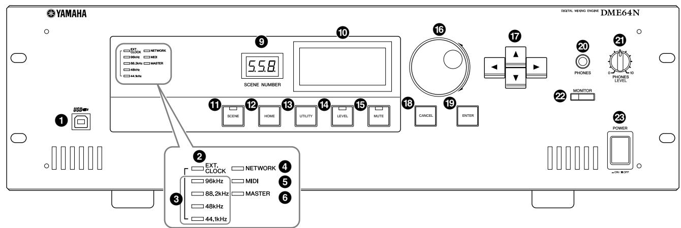
DME64N
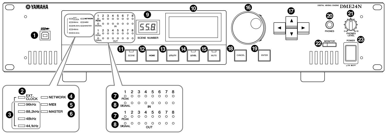
DME24N
1 [USB] Connector
A computer can be connected here when it is necessary to program or control the device. When a USB connection is to be used, the USB-MIDI driver must be installed on the computer. Refer to the DME Designer Installation Guide for installation instructions.
[EXT. CLOCK] Indicator
When a clock signal from an external device is selected, the indicator will light green. If the clock signal is not appropriate the indicator will flash red. The indicator will go out when the internal word clock is selected.
[96kHz] [88.2kHz] [48kHz] [44.1kHz] Indicator
Normally, the indicator corresponding to the current word clock frequency will light green. If a problem with the master clock is detected all of these indicators will flash red. 2 seconds after a problem is detected with an external master clock the internal clock will temporarily be selected. When this happens the indicator corresponding to the frequency of the internal clock will light green, and all other indicators will continue to flash red.
4 [NETWORK] Indicator
Lights while data communication is occurring via the [USB], [NETWORK], or [CASCADE] connector.
Received data causes the indicator to light in green, while transmitted data causes the indicator to light in orange. If a problem occurs the indicator will light in red.
[MIIDI] Indicator
Lights while data communication is occurring via the [MIDI] connector. Received data causes the indicator to light green, while transmitted data causes the indicator to light orange. The indicator will light green when reception and transmission occur simultaneously. If a problem occurs the indicator will light red.
[MASTER] Indicator
Lights green when the device is operating as the zone master (page 13). The indicator will not light if the device is operating as a zone slave. Refer to page 48 for zone master setup instructions.
[PEAK] Indicator (DME24N only)
Light red when a signal on the corresponding built-in analog audio input or output ([IN] and [OUT] connectors) reaches or exceeds -3 dB.
[ SIGNAL ] Indicator (DME24N only)
Light green when a signal with a level greater than -40 dB is present at the built-in analog audio inputs and outputs ([IN] and [OUT] connectors).
NOTE
The DME64N has no built-in analog audio inputs or outputs ([IN] and [OUT] connectors).
[SCENE NUMBER] Indicator
Shows the current scene number.
10 Display
Displays scene information and device parameters.
[SCENE] Button
Calls the scene recall/store display (page 43). The scene store display will appear if the button is held for longer than 2 seconds (page 43). The indicator will light green while the scene recall or store display is showing.
[HOME] Button
Directly recalls the home (main) display. If pressed while the main display is showing the [HOME] button steps through the user-defined parameter display pages (refer to page 42 in this manual).
[UTILITY] Button
Calls the output level display. If this button is held for longer than 2 seconds while the main display is showing the utility display will appear. Switches between the Utility display pages if pressed while the Utility display is showing.
LEVEL]Button
Calls the output level setup display (page 46). The indicator will light green.
[ MUTE ] Button
Calls the mute display (page 42). The indicator will light orange when mute is on. The indicator will light green when mute is off and the mute display is showing, and will be off if the mute display is not showing.
Dial
Adjusts the value of selected parameters.
17 [▲] [▲] [▼] [▶] Buttons
Move the display cursor in the corresponding directions.
18 [CANCEL] Button
Closes the window on the display.
[ENTER] Button
Confirms and enters a value or setting.
20 [PHONES] Jack
A pair of headphones can be plugged in here.
[PHONES LEVEL] Control
Adjusts the headphone volume. Even when the control is set to the minimum level, the sound at the headphones is not completely muted.
[MONITOR] Button
Calls the monitoring point slot selection display (page 44). When the [ENTER] button is pressed to select a slot, the monitoring point selection display will appear.
The spectrum analyzer display will then appear when the [ENTER] button is pressed to select a monitoring point. The indicator will light green while the monitoring slot/ point or spectrum analyzer display is showing.
23 [POWER] Switch
Turns mains power to the device on and off.
Rear Panel
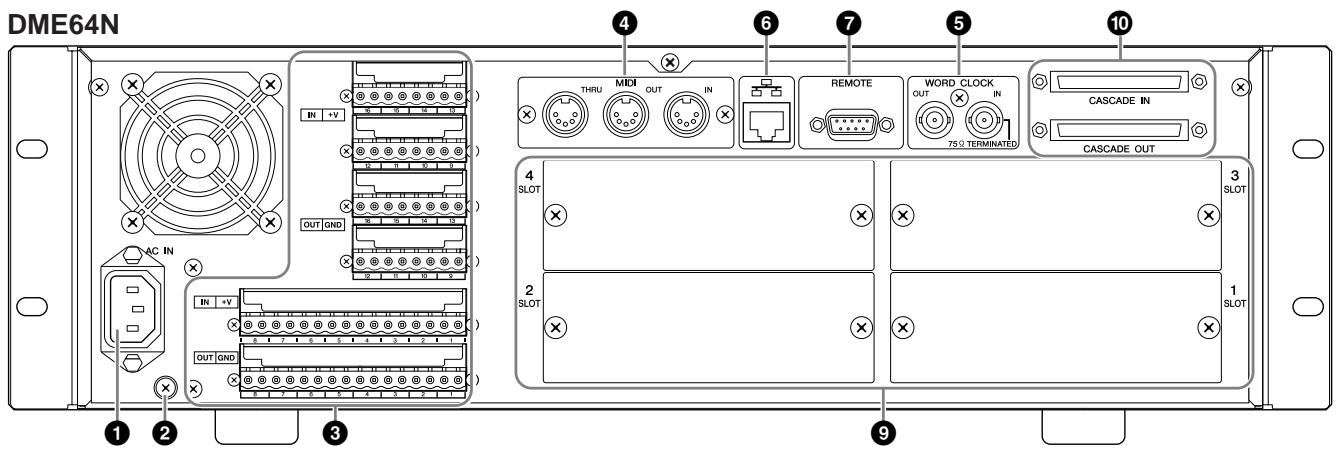
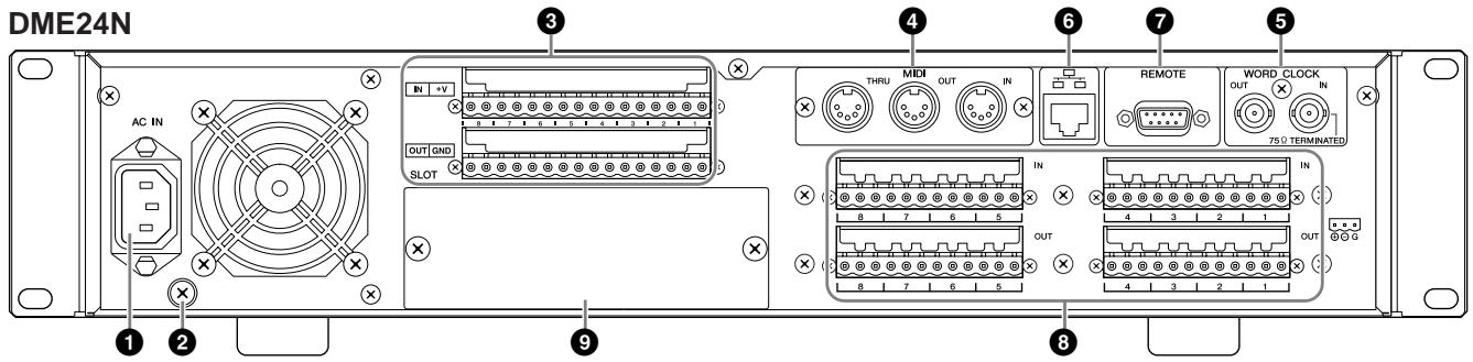
[AC IN] Connector
This is the device's three-pronged AC power connector. Connect to the AC mains using the supplied AC power cord. See "Preparation" on page 20 for details.
NOTE
Use the supplied AC cord clamp to prevent accidental disconnection of the AC power.
NOTE
When connecting to two-prong type AC mains outlets use the supplied plug adaptor.
Ground Screw
The supplied power cable has a three-prong plug that will ground the unit when plugged into an appropriate three-prong type AC mains outlet. When connecting to a two-prong type outlet that has a ground screw, use the supplied AC plug adaptor and connect the adaptor's ground lead to the ground screw. When connecting to a two-prong type outlet that does not have a ground screw be sure to connect the DME64N/24N ground screw to a confirmed ground point. Proper grounding can significantly reduce hum, noise, and interference, while stabilizing phase and imaging.
NOTE
Make sure that the device is securely grounded to a single ground point (e.g. either via a three-prong AC connection, or via the ground screw.)
NOTE
Connect the device to only one ground point.
Connecting the device to more than ground point can result in ground loops that can cause increased hum and noise.
[GPI] Connector
This Euroblock connector provides access to the unit's GPI (General Purpose Interface) interface for transfer of control signals to and from external equipment. The DME64N provides 16 channels of GPI input and output, while the DME24N provides 8 channels. Each input channel has an IN terminal and a +V terminal. Output channels each have an OUT terminal and a GND terminal. The open voltage at the +V terminal is 5V, while the IN terminal detects voltage changes from 0V 5V . The OUT terminals output either 0V or 5V . See "GPI Connection" on page 31 for connection details.
4 [MIDI IN] [MIDI OUT] [MIDI THRU] Connectors
These are standard MIDI connectors that handle reception and transmission of MIDI data: [MIDI IN] receives MIDI data, [MIDI OUT] transmits MIDI data, and [MIDI THRU] re-transmits MIDI data received at the [MIDI IN] connector. See "MIDI Connection" on page 30 for connection details.
5 [WORD CLOCK IN] [WORD CLOCK OUT] Connectors
These BNC connector receive and transmit word clock from and to external equipment. See "Word Clock Connection" on page 33 for connection details. Word clock settings are available via the device's Utility display WCLK page (see page 51 of this document).
[NETWORK] Connector
This is a 100Base-TX/10Base-T Ethernet connector for connection to a computer or other DME64N/24N units. Normally this connector will be connected to a network hub via an Ethernet "straight" cable. When two DME64N/24N units are to be directly connected a "cross" cable should be used.
[REMOTE] Connector
This 9-pin D-SUB connector allows connection to Yamaha AD824 or AD8HR remote head amplifiers or other RS-232C compatible controllers. Refer to page 34 for connection details.
[IN] [OUT] Connectors (DME24N only)
These are balanced Euroblock connectors for analog audio input and output. The analog signal from microphones or line sources such as CD players can be input via the IN connectors, while the OUT connectors can deliver analog output to powered speakers or recording equipment. 48V phantom power can be supplied to the IN connectors (page 54). Refer to page 35 for [IN] and [OUT] connection details.
NOTE
The [IN] and [OUT] connectors each have 24 terminal pins. Each of the eight inputs and outputs uses three pins - hot, cold, and ground. Use the supplied 3-pin Euroblock plugs to connect to the appropriate inputs and outputs.
I/O Slots
- Optional Yamaha or third-party mini-YGDAI cards can be plugged in here for system expansion. The DME64N has four I/O slots, while the DME24N has one.
- One expansion card can be plugged into each slot. Refer to "I/O Card Installation" on page 22 for installation details.
[ CASCADE IN] [CASCADE OUT] Connectors (DME64N only)
This 68-pin D-SUB connector can be connected to the CASCADE connector of other devices via a dedicated cascade cable. The CASCADE connector transmits and receives control, audio, and word clock signals. Refer to "Cascade Connection" on page 32 for connection details.
Preparation
Setup Procedure
Follow the steps outlined below to prepare the DME64N/24N for operation.
1. Install any required I/O cards.
Refer to "I/O Card Installation" on page 22 for details.
2. Connect the AC power cord.

Be sure to turn all devices OFF before connecting AC mains power.
Attach the cable clamp to prevent accidental disconnection.
Attaching the cable clamp.
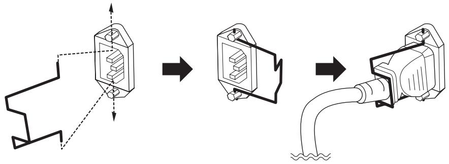
Be sure to properly ground the device to prevent possible electrical shock.
First plug the female-connector end of the AC cord into the [AC IN] socket on the rear panel of the DME64N/24N, then plug the male plug into an appropriate AC mains outlet. Make sure the AC power to be used complies with the conditions marked on the top cover of the device.

Use only the AC power cord supplied with the DME64N/24N. If the supplied cord is lost or damaged ands needs to be replaced, contact your Yamaha dealer. The use of an inappropriate replacement can pose a fire and shock hazard!
The type of AC power cord provided with the DME64N/24N may be different depending on the country in which it is purchased (a third prong may be provided for grounding purposes). Improper connection of the grounding conductor can create the risk of electrical shock. Do NOT modify the plug provided with the DME64N/24N. If the plug will not fit the outlet, have a proper outlet installed by a qualified electrician. Do not use a plug adapter which defeats the grounding conductor.
Security Cover Mounting
Security cover mounting screw holes (M3 size) are provided on the front panel of the unit. The spacings are 423mm width and 96mm (DME64N) / 52mm (DME24N) height. See “Dimensions” on page 68 for details. A security cover made by the customer or contractor can be attached to the front panel via these mounting holes to prevent accidental operation. Yamaha cannot supply a security cover.
When mounting a cover make sure that the screws used do not go deeper than 15 millimeters into the front panel. Also, to ensure that the cover does not come in contact with the panel controls, leave a space of about 20 millimeters between the front panel and the cover.
- Install the DME Designer software and necessary drivers on the computer to be used for zone control.
See the separate "DME Designer Installation Guide" for details.
- Connect the device to the computer and/or other equipment.
Refer to "Connection" on page 24 for details.
- Turn power to the computer, DME64N/24N, and related devices on. Press the DME64N/24N [POWER] switch to turn it on.

To prevent the initial power-on surge from generating a large noise spike or damaging your speaker system, turn devices on in the following order: audio sources, mixer and/or recorders, and finally power amplifiers. Reverse this order when turning power off.
No information will appear on the display the first time the device is turned on. The appropriate scene and other data must first be transferred to the device from the DME Designer.
Once the appropriate data has been transferred to the device, the current number and name will appear on the display:
If any scene data has been stored in the DME64N/24N, the current scene and its name will be displayed.
- Set up the DME64N/24N operation parameters.
See the "Utility Display" section on page 47 for details.
NOTE
The "NET" page settings must be set up as required before using the unit for the first time.
- Launch the DME Designer application on the computer.
DME Designer setup, operation, and data transfer instructions can be found in the DME Designer Manual.
This completes preparation of the DME64N/24N system.
I/O Card Installation
The DME64N has four I/O card slots, and the DME24N has one I/O card slot. The number of audio input channels available on the DME64N/24N can be increased by plugging the appropriate mini-YGDAI I/O card(s) into the available card slot(s).
Compatible I/O Cards
As of July 2004, Yamaha mini-YGDAI cards that can be used with the DME64N/24N are as follows:
| Card Name | Function | Input | Output | No. of Available Cards | |
| DME64N | DME24N | ||||
| MY8-AT | ADAT | 8 | 8 | 4 | 1 |
| MY8-TD | TDIF-1 | 8 | 8 | 4 | 1 |
| MY8-AE | AES/EBU | 8 | 8 | 4 | 1 |
| MY4-AD | ANALOG IN | 4 | - | 4 | 1 |
| MY8-AD | ANALOG IN | 8 | - | 4 | 1 |
| MY4-DA | ANALOG OUT | - | 4 | 4 | 1 |
| MY8-AD24 | ANALOG IN | 8 | - | 4 | 1 |
| MY8-AD96 | ANALOG IN | 8 | - | 4 | 1 |
| MY8-DA96 | ANALOG OUT | - | 8 | 4 | 1 |
| MY8-AE96S | AES/EBU | 8 | 8 | 4 | 1 |
| MY8-AE96 | AES/EBU | 8 | 8 | 4 | 1 |
| MY16-AT | ADAT | 16 | 16 | 4 | 1 |
| MY16-AE | AES/EBU | 16 | 16 | 4 | 1 |
| MY16-TD | TDIF-1 | 16 | 16 | 4 | 1 |
| MY16-C | CobraNet | 16 | 16 | 2 | 1 |
The input/output numbers above apply to 44.1/48kHz operation.
For the latest information on what cards can be used with the DME64N/24N, visit the Yamaha Pro Audio website at: http://www.yamahaproaudio.com/
- Make sure that the DME64N/24N power is OFF.
If the power is on, turn it off.
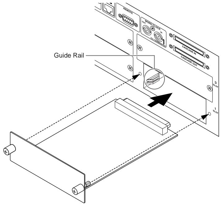
- Loosen the two card slot screws and remove the slot cover, as shown in the diagram.
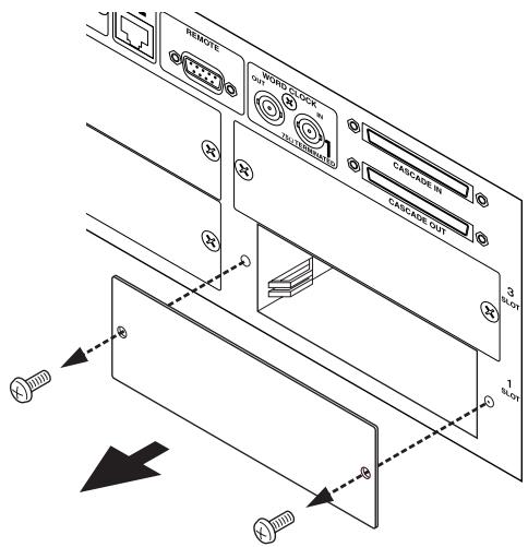
NOTE
The slot cover and screws will need to be re-attached if the I/O card is later removed from the slot, so keep them in a safe place.
- Slide the I/O card into the slots in the guide rails, as shown in the diagram, and push the card into the slot.
Be sure to push the card all the way back into the slot so that the card contacts make proper contact with the slot connector.
- Secure the card with the attached screws.

Be sure to tighten the screws securely. If the screws are left loose proper contact may be lost and malfunction of damage may result.
Connection
The DME64N/24N must be connected to other DME64N/24N units as well as other audio equipment, according to the audio system design.
Signal Types
DME64N/24N audio system signals can be broadly categorized as follows.
1. Audio
The DME64N/24N will be required to send and receive audio signals to and from other DME64N/24N units as well as other audio equipment. Audio signal transmission and reception will occur primarily via I/O cards installed in the unit's I/O card slot(s). The DME24N has 8 channels of built-in audio I/O that can be used without installing any extra cards.
2. Zone Control
Zone control signals control all DME64N/24N units and ICP1 control panels within the zone. There are two types of zone control signals, as follows:
- Signals for communication between the computer or mixer that controls the entire area and the zone master DME64N/24N.
- Signals for communication between the zone master DME64N/24N and other DME64N/24N within the zone.
The DME Designer application running on the area-control computer is used to send components and set parameters as required.
3. Device Control
These signals provide communication and control between individual devices. Included in this category are MIDI messages transferred between [USB] and [MIDI] connectors, GPI signals transferred between [GPI] connectors, and remote head amp control signals handle via the [REMOTE] connector.
4. Word Clock
Individual devices that handle the same digital audio signals must be synchronized to a single word clock of the same frequency. The DME64N/24N transmits and receives word clock via the [CASCADE IN] and [CASCADE OUT] connectors, the [WORD CLOCK IN] and [WORD CLOCK OUT] connectors, and via I/O cards plugged into the I/O card slots.
DME64N/24N Signal Types
| Connector | Audio Signal | Zone Control | Device Control | Word Clock | Page | |
| USB Connection | [USB] Connector | - | Control signals from computer to zone master DME64N/24N. | Transmission/reception of control signals (MIDI commands) between computer and DME64N/24N. | - | Page 26 |
| Ethernet Connection | [NETWORK] Connector | - | Control signals between computer and zone master, and between zone master and other DME64N/24N units in the zone. | - | - | Page 27 |
| MIDI Connection | [MIDI] Connector | - | - | Transmission/reception of control signals (MIDI commands) between MIDI controller and DME64N/24N. | - | Page 30 |
| GPI Connection | [GPI] Connector | - | - | Transmission/reception of GPI control signals between GPI device (GPI controller, etc.) and DME64N/24N. | - | Page 31 |
| CASCADE Connection (DME64N only) | [CASCADE] Connector | 32 channels of input/output. | Control signals from mixer to zone master DME64N/24N. | - | Word clock transmission and reception to and from other devices. | Page 32 |
| WORD CLOCK Connection | [WORD CLOCK] Connector | - | - | - | Word clock transmission and reception to and from other devices. | Page 33 |
| REMOTE Connection | [REMOTE] Connector | - | - | Control signal transmission and reception to and from head amplifier. | - | Page 34 |
| Audio I/O (DME24N only) | (Audio I/O Connectors) | 8 channels of input and output. | - | - | - | Page 35 |
| I/O Card | (I/O Slot) | Number of I/O channels depends on card. | - | Serial signal transmission/ reception (depending on function of card). | Word clock transmission and reception to and from other devices (depending on function of card). | Page 37 |
USB Connection
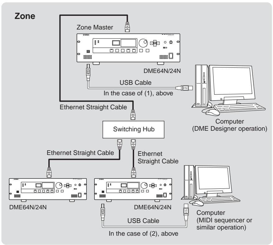
Connect the DME64N/24N [USB] connector to the computer's USB connector using a USB cable. USB connections can be used in the following two ways:
(1) Connect the computer to, and control the zone master DME64N/24N using the DME Designer.
(2) Connect to any individual DME64N/24N and control that DME64N/24N unit using MIDI commands from a MIDI sequencer or similar software.
DME Designer can be used for overall zone control, as well as sending components to the zone via the zone master.
When using MIDI commands from a MIDI sequencer to directly control a DME64N/24N, HOST (see page 52) should be set to USB-1 or USB-2.
NOTE
The correspondence between the MIDI commands to be received/transmitted and the scene parameters can be set up using the DME Designer.
NOTE
The USB port being used by the DME Designer cannot also be used by a MIDI sequencer or other application.
NOTE
When connecting a computer to a DME64N/24N via USB, the appropriate USB-MIDI driver must be installed on the computer. Refer to the DME Designer Installation Guide for details on installing the appropriate driver.
Make sure that the USB-MIDI driver THRU setting is "OFF."
Ethernet Connection ([NETWORK] Connector)
Connect the [NETWORK] connector on the rear panel of the DME64N/24N to the network switching hub via a straight Ethernet cable.
Ethernet connections can be used in the following two ways:
- Connect the computer to the zone master DME64N/24N.
- Connect the zone master DME64N/24N to zone slave DME64N/24N units.
Appropriate IP addresses must be assigned to all devices connected to an Ethernet network. Refer to the Utility display Net page (page 48 of this document) for IP address setting details.
NOTE
When connecting a computer to a DME64N/24N via Ethernet, the appropriate DME-N Network driver must be installed on the computer. Refer to the DME Designer Installation Guide for details on installing the appropriate driver.
A DME64N/24N Ethernet connection falls into the "Class C Network" category. In a class C network, of the assignable IP addresses "########.#####.#####.$$", "########.#####.#####" is the network address and "$$" is the host address. Devices assigned the same network address will function within the same zone. The host address range is 2 - 254. When the host address is "2" the device is the zone master, while host addresses from 3 to 254 are assigned to zone slaves. Only one zone master can be assigned in any one zone.
Devices in the same zone (devices having the same network address) can be directly connected using cross cables, or by using straight cables via a switching hub.
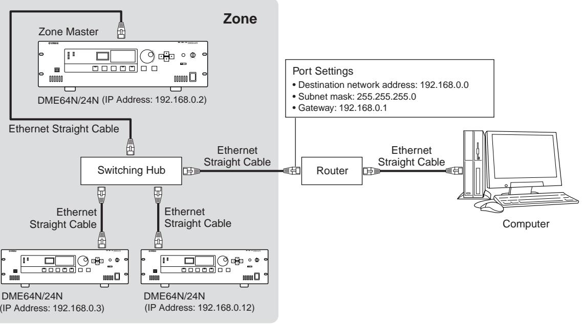
Devices in different zones (devices having different network addresses) can be connected via a router or layer-3 compliant switching hub.
DME64N/24N Units Directly Connected via Ethernet
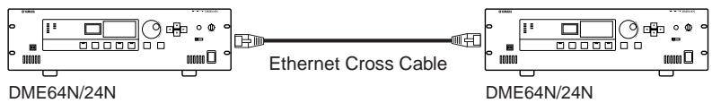
NOTE
A cross cable can be used to directly connect DME64N/24N and/or ICP1 units. In such cases set the Link Mode parameters in the network settings pages of both units the same way (page 49 of this document).
Control from a Computer Having the Same Network Address
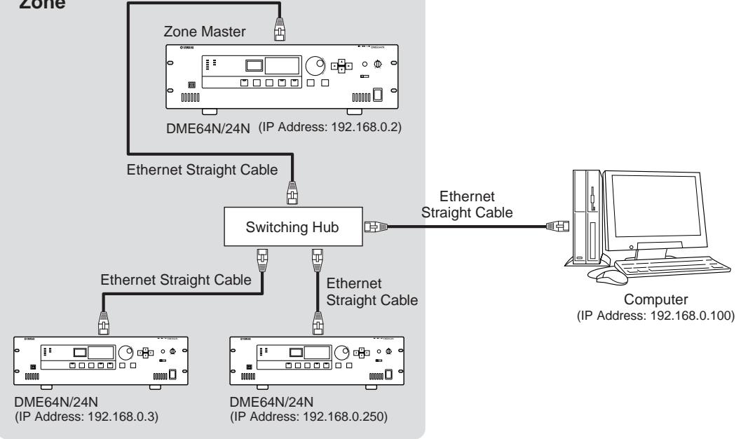
Zone
NOTE
The IP addresses in the diagram are examples.
NOTE
Use a switching hub that is compatible with 100Base-TX/10Base-T network speeds.
When using category 5 UTP cable (Unshielded Twisted Pair), the total length of the cables connecting the DME64N/24N to the hub or control panel unit can be up to 100 meters. Due to differences in cable and switching hub performance, however, proper operation at the maximum length cannot be guaranteed in some cases. The maximum usable cable length will also be reduced if joint connectors, cross cable converters, or other extension adaptors are used.
Control from a Computer Having a Different Network Address
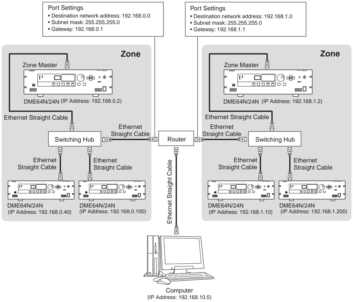
Connecting Multiple Zones
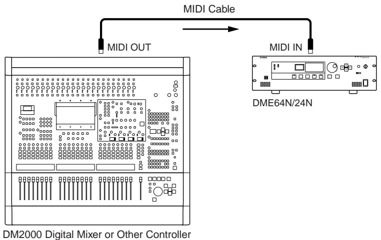
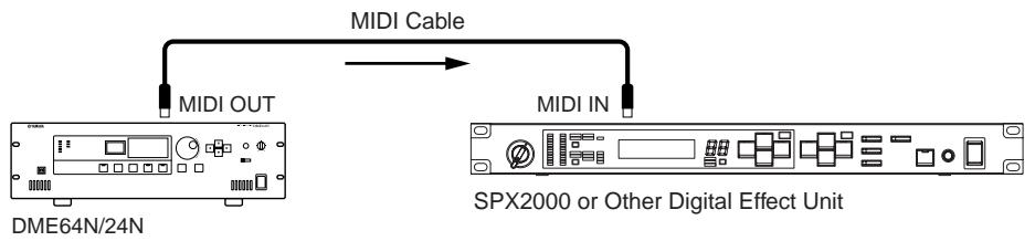
MIDI Connection
In this case connection is made to the rear-panel [MIDI] connectors. MIDI commands are sent to the DME64N/24N from a MIDI device.
NOTE
Refer to "MIDI Page" on page 52 for MIDI setup details.
NOTE
The DME Designer can be used to set up the system so that scene recall operations and user parameter control can be carried out from connected MIDI devices. Refer to the DME Designer manual for details.
By connecting the [MIDI OUT] terminal of a digital mixer (such as the DM2000) to the [MIDI OUT] of the DME64N/24N and making the proper settings on the mixer and the DME64N/24N, you can change scenes by sending program change messages from the mixer.
If the [MIDI OUT] connector of the DME64N/24N is connected to the [MIDI IN] connector of an SPX2000 or similar digital effect unit, and if the DME64N/24N and SPX2000 are set up appropriately, DME64N/24N program change operations will case the corresponding effect to be recalled on the effect unit.
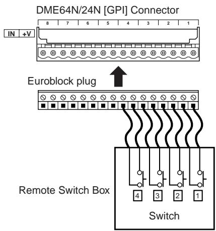
GPI Connection
GPI (General Purpose Interface) device (GPI controller, etc.) can be connected to the rear-panel [GPI] connectors. Using GPI a variety of control signals can be transferred between the DME64N/24N and external controllers or other devices. The optional CP4SW, CP4SF, and CP1SF control panels are also connected via GPI.
NOTE
For more information on the CP4SW, CP4SF, and CP1SF control panels refer to "CP4SW, CP4SF, and CP1SF" in the Appendix of this manual (page 59).
The DME64N provides 16 channels of GPI input and output, and the DME24N provides 8 channels. Each input channel has an IN terminal and a +V terminal. Each output channel has an OUT terminal and a GND terminal. The +V terminals have an open-terminal voltage of 5 volts. The IN terminals can detect a full range of input voltages from 0V through 5V, while the OUT terminals output either 0V or 5V.
The parameters for each GPI input and output are assigned via the DME Designer application.
NOTE
The DME Designer can be used to set up the system so that scene recall operations and user parameter control can be carried out from connected GPI control devices. Refer to the DME Designer manual for details.
Euroblock connectors are used for all GPI input and output connections. Euroblock connection methods are described in "Euroblock Connection" on page 35 in this manual.
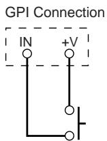
Example: Controlling the DME64N/24N from a switch.
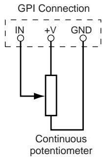
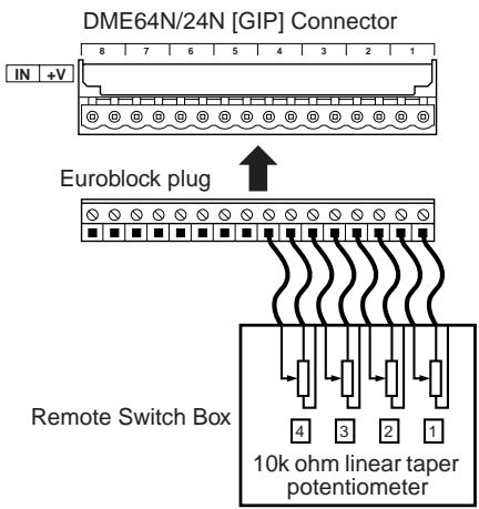
Example: Controlling the DME64N/24N via a 10k ohm linear taper potentiometer.
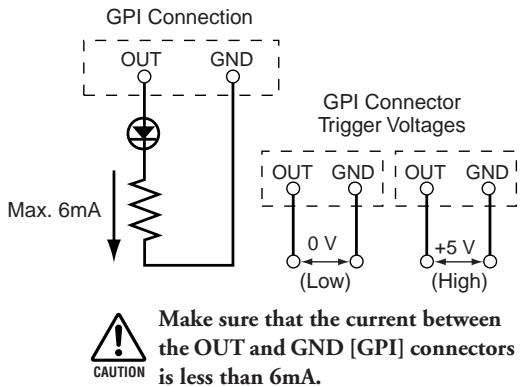
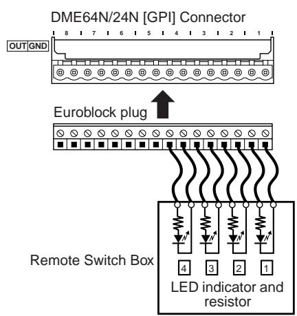
Example: Lighting external LED indicators from the DME64N/24N.
NOTE
GPI connector calibration procedure is described on page 53 of this manual, in the Utility display GPI page.
CASCADE Connection (DME64N only)
The rear-panel [CASCADE] connector can be connected to the [CASCADE] connector on another DME64N/24N or other compatible device via a dedicated cascade cable for bidirectional transfer of control, audio, and word clock signals. The communication direction automatically switches to unidirectional when connecting to a mixer such as the PM5D, or bidirectional when connecting to another DME64N/24N unit. In the unidirectional mode the audio signal flow is from the [CASCADE OUT] connector to the [CASCADE IN] connector. In the bidirectional mode signal flow also occurs in the reverse direction via the same cable. The total number of audio channels that can be connected to a mixer or DME64N/24N unit is 32. Word clock is continuously output from both the [CASCADE IN] and [CASCADE OUT] connectors, and is received by the corresponding [CASCADE IN] or [CASCADE OUT] connector on the connected device. In all cases the [CASCADE OUT] of one device must be connected to the [CASCADE IN] connector of the other. Do not connect [CASCADE IN] to [CASCADE IN], or [CASCADE OUT] to [CASCADE OUT].
NOTE
Maximum length by the optional dedicated Cascade cables
Unidirectional Cascade connection: 200m (44.1/48kHz), 100m (88.2/96kHz)
Bidirectional Cascade connection: 100m (44.1/48kHz), 30m (88.2/96kHz)
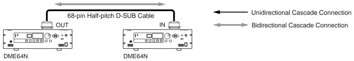
Cascade Connection Example
NOTE
Never create a full cascade loop using only DME64N units!
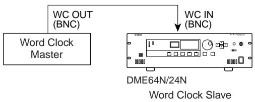
WORD CLOCK Connection
Word clock signals are transferred to and from external devices via the [WORD CLOCK IN] and [WORD CLOCK OUT] connectors. The [WORD CLOCK OUT] connector can be used to supply the DME64N/24N word clock to external equipment. Word clock is continuously output by the DME64N/24N during normal operation. The word clock signal from an external device can be received via the [WORD CLOCK IN] connector.
NOTE
Word clock can also be received and transmitted via a mini-YGDAI card installed in an I/O slot, or the [CASCIDE IN] and [CASCADE OUT] connectors. It is necessary to specify whether the DME64N/24N will use the internal word clock or an external word clock for synchronization. Refer to the Utility display WCLK page described on page 51 of this manual for details.
NOTE
A device transmitting the word clock signal that will be used by other devices for synchronization is the "word clock master," while devices received the word clock are "word clock slaves."
To distribute the word clock signal from one device to multiple slave devices, either a word clock distribution box or daisy-chained connection can be used.
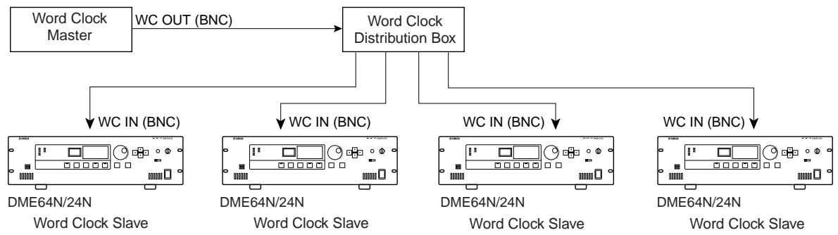
Distribution Box Connection
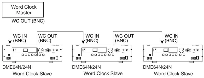
Daisy Chain Connection
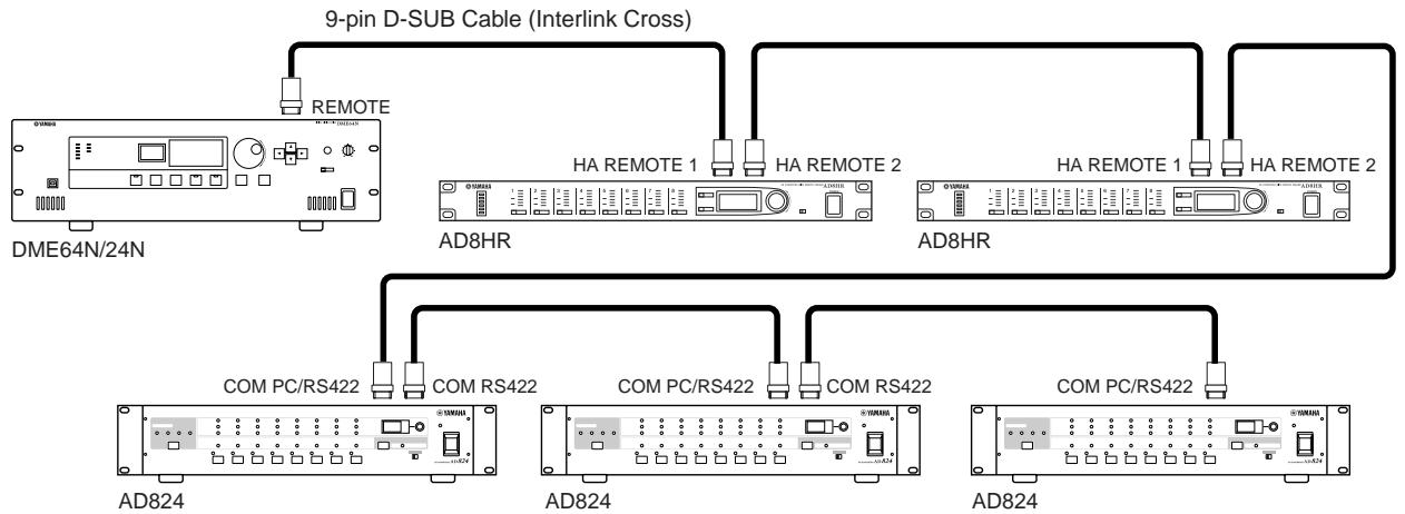
REMOTE Connection
The [REMOTE] connector can be connected to remotely-controllable Yamaha AD8HR or AD824 head amplifiers (preamplifiers), or RS-232C compatible controllers. Up to 8 head AD8HR/AD824 head amplifiers can be connected. Control can be handled either from the Utility display HA page (described on page 54 of this manual), or from the DME Designer application.
When connecting to a combination of AD8HR and AD824 head amplifiers, be sure to place the AD8HR units closest to the DME64N/24N in the chain, otherwise the AD8HR unit(s) may not be properly recognized by the DME64N/24N.
NOTE
Only control signals are transmitted and received via the REMOTE connection. Audio connections must be made separately.
When connecting an RS-232C compatible controller set the Utility display "Misc" page "Remote" parameter to "COM (RS232C)" - see page 51 of this manual.
Analog Audio Connection ([IN] and [OUT] Connectors) (DME24N only)
The DME24N includes [IN] and [OUT] connectors for 8 channels of analog audio input and output. Wire the supplied Euroblock plugs as shown below. Head amplifier gain and phantom power settings can be made via the Utility display HA page described on page 54 of this manual, or via the DME Designer application.
Cable Preparation
Prepare cables to be attached to a Euroblock plug as shown below.
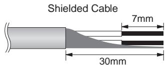

Be sure to use shielded cable.

Do not tin (plate with solder) the exposed sections of the cable.
Euroblock Connection
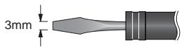
NOTE
A slotted screwdriver with a blade width of about 3 millimeters is recommended.
1. Loosen terminal screws.
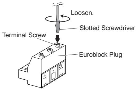
2. Insert cables.
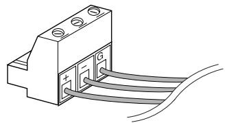
3. Securely tighten terminal screws.
Pull the cables (not too strongly) to confirm that they are securely connected.
4. Plug the Euroblock plug into the panel connector.
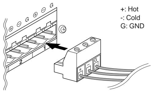
NOTE
Analog audio input and output can also be connected via an I/O Card installed in a DME64N/24N I/O card slot.
I/O Slots
The DME64N has four I/O card slots, and the DME24N has one I/O card slot. The number of audio input channels available on the DME64N/24N can be increased by plugging the appropriate mini-YGDAI I/O card(s) into the available card slot(s). Some types of cards also provide control and/or word clock transmission and reception functionality.
Refer to "I/O Card Installation" on page 22 of this manual for card installation instructions.
For the latest information on what cards can be used with the DME64N/24N, visit the Yamaha Pro Audio website at: http://www.yamahaaproaudio.com/
CobraNet Connection
If an MY16-C CobraNet interface card is installed in a DME64N/24N card slot it becomes possible to transfer audio, control, and word clock signals via a CobraNet network. MY16-C equipped DME64N/24N units can be connected to any other CobraNet compatible equipment for broad-ranging audio and word clock signal networkability. Refer to the MY16-C Owner's Manual for CobraNet network details.
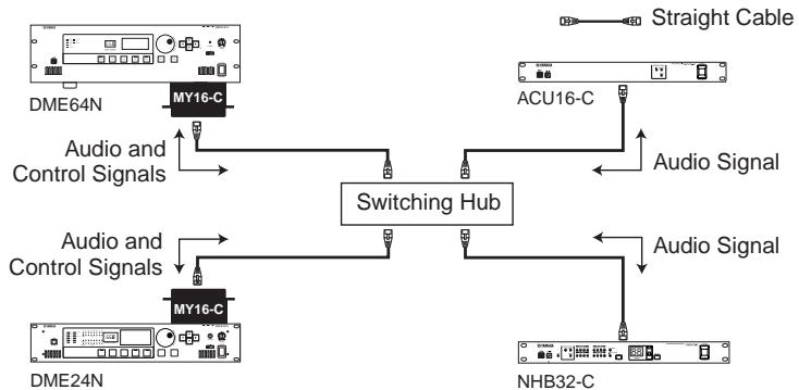
Example: Connection to CobraNet Devices
NOTE
Control signals cannot be transferred between devices that do not use the MY16-C card in some cases.
NOTE
CobraNet is an audio networking system developed by Peak Audio (a division of Cirrus Logic, Inc.) that allows real-time transmission and reception of multiple channels of uncompressed digital audio signals via a Fast Ethernet (100 megabits/sec.) network. A single network cable can handle a maximum of 64 channels (128 channels bidirectional) of audio data.
The Peak Audio home page can be viewed on the web at: http://www.pekaudio.com/
Panel Operation and Displays
The Panel Buttons and Displays
By pressing the panel buttons it is possible to select the DME64N/24N Main display, Utility display, and Parameter Edit displays that allow individual settings to be edited and changed. refer to the pages listed below for more detailed information about each display.
[HOME] button Main Display (Page 39)
The Main display can be directly recalled from any display other than the Main display by pressing the [HOME] button. The Main display shows the current scene information
![YAMAHA DME64NV1 - [HOME] button Main Display (Page 39) - 1](/content/2025/01/114571/images/dc3e2b10bfe1a70f0dc6fb2623541f24d379e9ba288dee3b12c79dd377db7db4.jpg)
[HOME] button User-defined Parameter Page Selection (Page 42)
Pressing the [HOME] button while the Main display is shown sequentially selects the four user-defined parameter pages.
![YAMAHA DME64NV1 - [HOME] button User-defined Parameter Page Selection (Page 42) - 1](/content/2025/01/114571/images/8214034edcaa1b21bc21fb8029412c4e728f95b8b1fe831777c0dc99f95669db.jpg)
Main display
Switches the pages of the user-defined parameter
[MUTE] button Mute Display (Page 42)
[LEVEL] button Output Level Display (Page 42)
[SCENE] button Scene Recall Display (Page 43)/Scene Store Display (Page 43)
These buttons can be pressed from the Main or Utility displays to directly call the related parameter edit displays.
[MONITOR] button Monitor Point Selection Display (Page 44)
This function is useful for level monitoring. When the button is pressed the monitor point selection display will appear, and the spectrum analyzer display will appear when a selection has been made.
[UTILITY] button Utility Display (Page 47)
The Utility display appears when the [UTILITY] button is pressed for longer than two seconds while the Main display is showing.
The Utility display includes a number of pages that can be selected in sequence by repeatedly pressing the [UTILITY] button.
Main Display
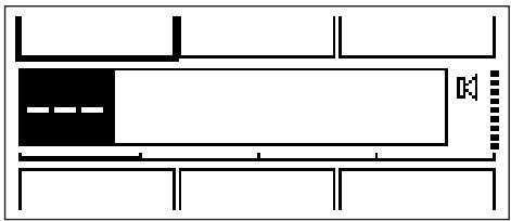
The Main display will appear in a few seconds after the power is turned on. The Main display shows information about the current scene.
NOTE
Nothing will appear on the display if no scene data is stored in the DME64N/24N scene memory (this is the case when the unit is initially shipped, for example).
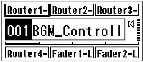
Up to 24 parameters can be accessed from the DME64N/24N or ICP1 control panel for each scene. Six parameters are shown on the Main display at a time.
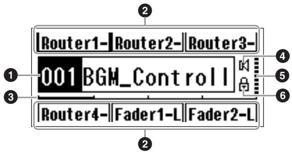
Scene Information
The current scene number and name. Scene names can be entered by using the DME Designer application.
A maximum of 12 one-byte (Roman) characters can be displayed in a scene name. When "two-byte" characters are to be used for languages such as Japanese, the total number of displayable characters is reduced accordingly.
When the power is turned on the last scene selected before the power was turned off is automatically recalled.
User-defined Parameter Names
Displays the user-defined parameters. The parameters are specified by using the DME Designer application.
A maximum of 24 parameters can be made available for user control, but only six parameters can be shown in any one display page. Press the [HOME] button to switch to other available parameter pages. A maximum of 8 one-byte (Roman) characters can be displayed in a parameter name. When "two-byte" characters are to be used for languages such as Japanese, the total number of displayable characters is reduced accordingly.
Parameters are selected for editing by using the cursor buttons- [ ][ ][ ][ ] - to select the parameter, and then pressing [ENTER].
Page Scroll Bar
The scroll bar provides an indication of which parameter page is currently being displayed. 4 pages are available, and the scroll bar moves one position to the right each time the [HOME] button is pressed and a new page of parameters is selected, and then back to the leftmost position after the rightmost position has been reached.
Mute Indicator
Shows the current mute ON/OFF status.
Mute ON
K:Mute OFF
Output Level Indicator
Displays the current output level in 10 increments. The longer the "bar," the higher the output level.
Panel Lock Icon
This icon appears when the panel lock function is turned ON.
:PanelLockON (Panelcontrolslocked)
Panel Lock
The panel controls can be "locked" to prevent accidental mis-operation.
To activate the panel lock function simultaneously press and hold the [HOME] and [ENTER] buttons for longer than 2 seconds.
The panel lock icon will appear on the Main display when the panel is locked.
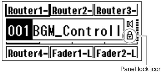
Panel Lock can be disengaged by pressing the [CANCEL] button for longer than 2 seconds.
NOTE
The panel lock function can be set up to lock just the panel buttons ("Key Only"), or the panel buttons and GPI control ("Key+GPI"). You can also select whether or not the panel lock function is automatically engaged when the unit is initially turned on. This selection can be made via the Utility display "Lock" page (refer to the page 50).
Parameter Edit Displays
Parameter Edit displays will appear when the [SCENE], [MUTE], [MONITOR] or other button is pressed to allow scene changes, level adjustment, and other settings to be edited as required. Parameter Edit displays are also used to edit utility parameters.
In most cases the desired parameter edit page can be accessed by selecting the item you want to edit in the appropriate display by using the cursor [ ], [▲], [▼], and [▶] buttons, and then pressing the [ENTER] button.
There are basically three types of parameters that can be accessed via a Parameter Edit display:
- Numeric values
Lists
ON/OFF switches
Numeric Parameters
Numeric parameters can be edited in a number of ways, and depending on the parameter a fader, knob, or minimum and maximum values may appear to the left of the numeric value.
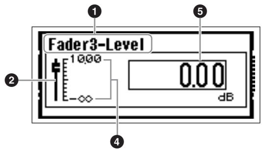
A Numeric Value with a fader
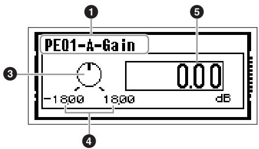
A Numeric Value with a Knob
1 Name of parameter selected for editing
Fader
3 Knob
4 Minimum and maximum values
Current value
Some Parameter Edit displays have just one numeric parameter, while other may have two or more.
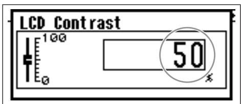
Parameter Edit Display with One Numeric Parameter
- Numeric values can be changed by rotating the dial. Dial rotation produces an immediate, corresponding change in the selected value.
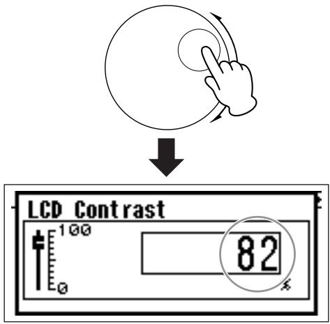
- Press the [ENTER] button to close the Parameter Edit display after the value(s) have been edited as required.
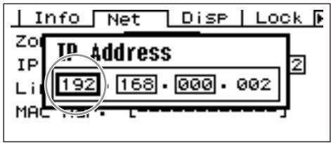
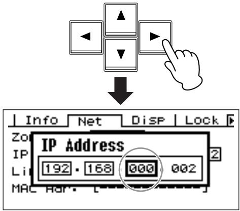
Parameter Edit Display with Multiple Numeric Parameters
- Use the cursor buttons - [▲] [▲] [▼] [▶] - to select the value to be edited.
- DIGITAL MIXING ENGINE
- DME64N / DME24N
- Owner's Manual
- Explanation of Graphical Symbols
- IMPORTANT SAFETY INSTRUCTIONS
- WARNING
- FCC INFORMATION (U.S.A.)
- IMPORTANT NOTICE: DO NOT MODIFY THIS UNIT!
- IMPORTANT NOTICE FOR THE UNITED KINGDOM
- Connecting the Plug and Cord
- WARNING: THIS APPARATUS MUST BE EARTHED
- NEDERLAND/THE NETHERLANDS
- ADVARSELI!
- Power supply/Power cord
- Do not open
- Water warning
- If you notice any abnormality
- CAUTION
- Location
- Connections
- Maintenance
- Handling caution
- Backup battery
- Foreword
- Contents
- DME64N/24N Audio System Overview 9
- The Controls and Connectors 16
- Preparation 20
- Panel Operation and Displays 38
- Appendix 56
- About the Documentation
- DME64N/24N Owner's Manual (This document)
- DME Designer Installation Guide
- DME Designer Owner's Manual (PDF file)
- Supplied Accessories
- DME64N and DME24N I/O Configuration
- Options
- Control Panels
- NOTE
- mini-YGDAI (Yamaha General Digital Audio Interface) I/O Cards
- DME64N/24N Audio System Overview
- The DME64N/24N Configurable Digital Mixing Engine
- Matrix Output Expansion
- Outboard Signal Processing
- Output Processor
- System Examples
- Single DME24N: A Meeting Room Installation
- Multiple DME64N: Large Stadium Or Multi-purpose Hall System
- Single DME64N: Sound Reinforcement
- DME64N/24N Audio System Network
- DME64N/24N Audio System Control
- Components & Parameters
- Configurations
- User-defined Parameters
- Scenes
- DME Designer
- The Controls and Connectors
- Front Panel
- [USB] Connector
- [EXT. CLOCK] Indicator
- [96kHz] [88.2kHz] [48kHz] [44.1kHz] Indicator
- [NETWORK] Indicator
- [MIIDI] Indicator
- [MASTER] Indicator
- [PEAK] Indicator (DME24N only)
- [ SIGNAL ] Indicator (DME24N only)
- [SCENE NUMBER] Indicator
- Display
- [SCENE] Button
- [HOME] Button
- [UTILITY] Button
- LEVEL]Button
- [ MUTE ] Button
- Dial
- [▲] [▲] [▼] [▶] Buttons
- [CANCEL] Button
- [ENTER] Button
- [PHONES] Jack
- [PHONES LEVEL] Control
- [MONITOR] Button
- [POWER] Switch
- Rear Panel
- [AC IN] Connector
- Ground Screw
- [GPI] Connector
- [MIDI IN] [MIDI OUT] [MIDI THRU] Connectors
- [WORD CLOCK IN] [WORD CLOCK OUT] Connectors
- [NETWORK] Connector
- [REMOTE] Connector
- [IN] [OUT] Connectors (DME24N only)
- I/O Slots
- [ CASCADE IN] [CASCADE OUT] Connectors (DME64N only)
- Preparation
- Setup Procedure
- Install any required I/O cards.
- Connect the AC power cord.
- Attaching the cable clamp.
- Security Cover Mounting
- I/O Card Installation
- Compatible I/O Cards
- Connection
- Signal Types
- Audio
- Zone Control
- Device Control
- Word Clock
- USB Connection
- Ethernet Connection ([NETWORK] Connector)
- DME64N/24N Units Directly Connected via Ethernet
- Control from a Computer Having the Same Network Address
- Control from a Computer Having a Different Network Address
- Connecting Multiple Zones
- MIDI Connection
- GPI Connection
- CASCADE Connection (DME64N only)
- WORD CLOCK Connection
- REMOTE Connection
- Analog Audio Connection ([IN] and [OUT] Connectors) (DME24N only)
- Cable Preparation
- Euroblock Connection
- Loosen terminal screws.
- Insert cables.
- Securely tighten terminal screws.
- Plug the Euroblock plug into the panel connector.
- CobraNet Connection
- Panel Operation and Displays
- The Panel Buttons and Displays
- [HOME] button → Main Display (Page 39)
- [HOME] button → User-defined Parameter Page Selection (Page 42)
- [MUTE] button → Mute Display (Page 42)
- [MONITOR] button → Monitor Point Selection Display (Page 44)
- [UTILITY] button → Utility Display (Page 47)
- Main Display
- Scene Information
- User-defined Parameter Names
- Page Scroll Bar
- Mute Indicator
- Output Level Indicator
- Panel Lock Icon
- Panel Lock
- Parameter Edit Displays
- Numeric Parameters
Brand : YAMAHA
Model : DME64NV1
Category : Audio signal processor