
XD150FX-SM - AV Switch Adder - Free user manual and instructions
Find the device manual for free XD150FX-SM Adder in PDF.

| Product Type | AV Switch |
| Brand | Adder |
| Model | XD150FX-SM |
| Number of Inputs | 4 |
| Number of Outputs | 1 |
| Input Connectors | 15-pin VGA (D-sub) |
| Output Connector | 15-pin VGA (D-sub) |
| Maximum Video Resolution | 1920 x 1200 at 60 Hz |
| Audio Support | Embedded stereo audio |
| Remote Control | Infrared (IR) remote included |
| Switching Method | Push-button or IR remote |
| Dimensions (W x D x H) | 200 x 100 x 30 mm |
| Weight | 0.5 kg |
| Power Supply | 5V DC, 1A via included adapter |
| Housing Material | Metal |
| Operating Temperature | 0 to 40 °C |
| Certifications | CE, RoHS |
| Package Contents | Switch, IR remote, power adapter, user manual |
| Warranty | 2 years |
| Mounting | Desktop |
| Maintenance | Clean with a soft, dry cloth |
| Safety | Use only the supplied power adapter; avoid exposure to liquids |
| Spare Parts / Repairability | No user-serviceable parts; contact Adder support for repairs |
Frequently Asked Questions - XD150FX-SM Adder
User questions about XD150FX-SM Adder
0 question about this device. Answer the ones you know or ask your own.
Ask a new question about this device
Download the instructions for your AV Switch in PDF format for free! Find your manual XD150FX-SM - Adder and take your electronic device back in hand. On this page are published all the documents necessary for the use of your device. XD150FX-SM by Adder.
USER MANUAL XD150FX-SM Adder
AdderLink XD150FX features 3
Supplied items 4
Optional extras....5
Installation
Locations 6
Connections 6
Fiber optic link....7
Transmitter video link 8
Transmitter audio links 8
Transmitter USB link 9
Transmitter serial link....9
Transmitter management port link 10
Transmitter power connection .... 11
Receiver video display 12
EDID management....12
Receiver audio devices....12
Receiver USB devices....13
Receiver serial link....13
Receiver power connection....14
Configuration
Accessing the management application....15
The Configure page....16
The Maintenance page 17
Operation
Indicators 18
Resetting a module....19
Further information
Getting assistance 20
Appendix I - Options port pin-out....21
Appendix 2 - Open source licenses....22
Warranty 23
Safety information....23
Radio frequency energy 24
Index

Introduction

WELCOME
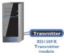
Thank you for choosing the AdderLink XD150FX extender modules. Using fiber optic links, these compact modules allow you to transfer the multiple connections listed below up to 4 kilometers from a host computer (see Transmission distances on the right).
The high grade screening employed within the metal case enclosures combined with the immunity from interference of the fiber optic links make the AdderLink XD150FX modules highly suitable for use in 'noisy' industrial environments.
AdderLink XD150FX extender modules provide support for:
• High quality single- or dual-link DVI digital video (up to 2560 x 2048 @60Hz),
• USB keyboard and mouse plus two other USB devices (up to USB 2.0).
• An RS232 serial device at speeds up to 115200 baud,
- Mono microphone,
- Stereo speakers,
• Line-level audio in/out connections.
The AdderLink XD150FX extender modules are totally transparent in operation, leaving you free to use your computer as though you're still sitting next to it.
Transmission distances
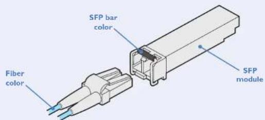
The choice of fiber used with the AdderLink XD150FX modules has a considerable effect on the distance over which operation can take place. Using multi-mode fiber you can achieve distances up to 400m (1,312 feet); whereas, by using single-mode fiber (and accompanying SFP modules), the achievable maximum distance is increased to 4km (2.5 miles):
Distance Fiber type Fiber color code SFP module SFP bar color
70m OMI (TIA-492AAAA) Orange SFP-MM-LC-4G Black
150m OM2 (TIA-492AAAB) Orange SFP-MM-LC-4G Black
380m OM3 (TIA-492AAAC) Aqua SFP-MM-LC-4G Black
400m OM4 (TIA-492AAAC) Aqua SFP-MM-LC-4G Black
4km OS1 (TIA-492C000) Yellow SFP-SM-LC-4G Blue OS2 (TIA-492E000) Yellow SFP-SM-LC-4G Blue
Fiber optic link (up to 4km)
Receiver
XD150FX
Receiver module

One dual-link DVI-D display Four USB devices One RS232 serial device Stereo speakers plus microphone
ADDERLINK XDI50FX FEATURES
The transmitter and receiver modules are contained within slimline metal casings that measure just 169 × 120 × 31 mm.


SUPPLIED ITEMS

natural_image
Two identical electrical devices with cables and connectors, no text or symbols visible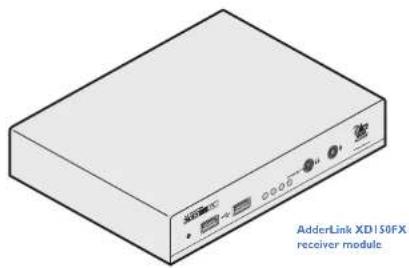
natural_image
Isometric illustration of a beige electronic device labeled 'AdderLink XD150FX receiver module' (no other text or symbols)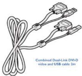
natural_image
Illustration of a combined dual-link DVI-D video and USB cable (2m) with two connectors and coiled cables (no text or symbols on the diagram itself)
natural_image
Two identical pairs of connected audio cables (no text or symbols visible)2 x audio cable 3m (3.5mm stereo jacles)
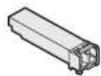
2 x SFP modules with LC connectors
(single- or multi-mode)
Muld mode: SFP-MM-LC-4G
Single mode: SFF-5M-LC-4G
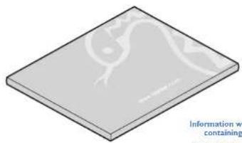
Information wallet
containing:
Quick setup guide
Light self-adhesive rubber feet
safely document

OPTIONAL EXTRAS
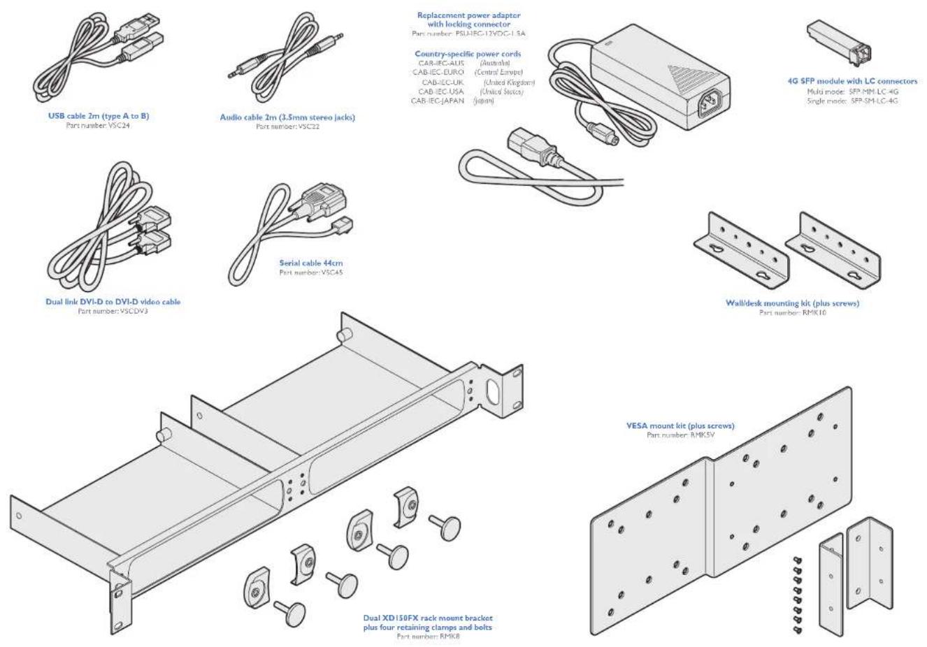
Country-specific power cords
CAR-IEC-AIDS (Australia) CAR-IEC-EURO (Central Festival)
CAB-IEC-UK (United Kingdom)
CAB (EC USA (United States)
CAB-IEC-JAPAN (Japan)
Multi mode: SFP-MM-LC-4G
Single mode: SFP-SM-LC-4G

Installation
LOCATIONS
Please consider the following important points when planning the position of the AdderLink XD150FX modules:
- Situate the transmitter module close to the system to which it will be connected and near to a source of mains power. Place the receiver module in similar close proximity to the peripherals that it will connect with, plus a source of mains power.
- Consult the precautions listed within the Safety information section.
- Connections do not need to be carried out in the order given within this guide, however, where possible connect the power in as a final step.
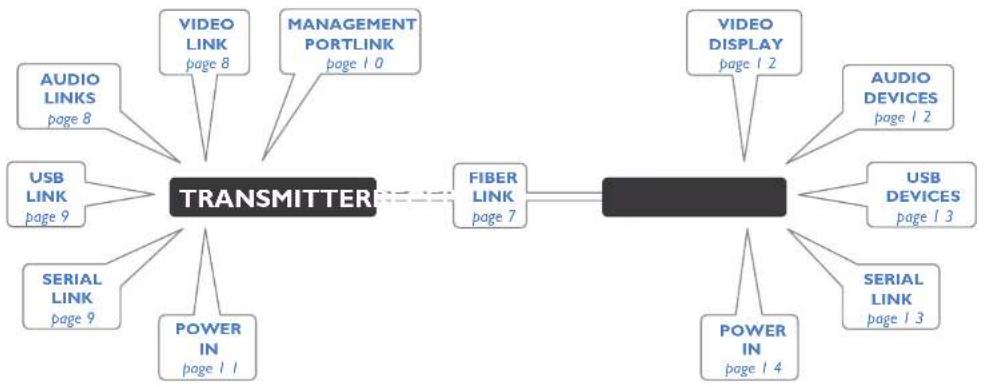
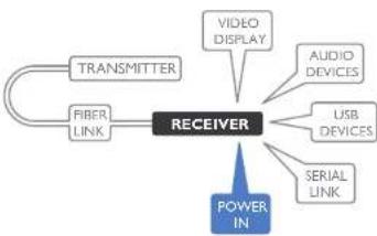
CONNECTIONS
Installation involves linking the AdderLink XD150FX Transmitter module to various ports on the host computer, while the AdderLink XD150FX Receiver module is attached to your peripherals:
flowchart
graph LR
    A["TRANSMITTER"] --> B["FIBER LINK page 7"]
    A --> C["VIDEO DISPLAY page 2"]
    A --> D["AUDIO LINKs page 8"]
    A --> E["USB LINK page 9"]
    A --> F["SERIAL LINK page 9"]
    A --> G["POWER IN page 11"]
    A --> H["MANAGEMENT PORTLINK page 10"]
    A --> I["VIDEO LINK page 8"]
    A --> J["AUDIO DEVICES page 2"]
    A --> K["USB DEVICES page 3"]
    A --> L["POWER IN page 4"]
    A --> M["SERIAL LINK page 3"]
Click a connection to see details

Fiber optic link
Each pair of AdderLink XD150FX modules are supplied together with SFP fiber optic modules of your choice (single or multi-mode). The fiber optic cable used must match the SFP type and also be of a suitable type for the distance being covered. See see Transmission distances for details.
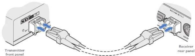
To make the fiber optic link
IMPORTANT: Ensure the power supply is off/disconnected before inserting or removing an SFP module.
1 Remove the SFP module from its protective packing and insert it fully into the empty slot on the AdderLink XD150FX. The XD150FX transmitter slot is located on the front panel; the XD150FX receiver slot is situated on the rear panel.

2 Repeat for the other SFP module on the other XD150FX.
3 For each SFP module, remove the black rubber insert that protects the sensors.
4 If fitted, remove the dual inserts that protect the fiber optic connector.
5 Insert the fiber optic connector into the SFP module so that it clicks into place.
6 Repeat steps 4 and 5 at the other end.

flowchart
graph LR
    A["TRANSMITTER"] --> B["FIBER LINK"]
    A --> C["RECEIVER"]
    A --> D["VIDEO LINK"]
    A --> E["VIDEO DISPLAY"]
    A --> F["AUDIO LINKS"]
    A --> G["USB LINK"]
    A --> H["SERIAL LINK"]
    A --> I["POWER IN"]
    A --> J["AUDIO LINKS"]
    A --> K["VIDEO LINK"]
    A --> L["MGMT LINK"]
    A --> M["AUDIO DEVICES"]
    A --> N["USB DEVICES"]
    A --> O["SERIAL LINK"]
Note: In order to maintain a high level of confidence in the fiber optic link, the SFP's used must be those supplied by Adder: (SFP-MM-LC-4G or SFP-SM-LC-4G).
If alternative parts are used, the system will detect this and will flash the front panel LNK indicator.
To remove an SFP module
If fitted, remove the fiber optic connector from the SFP module (press down on the upper tab of the fiber optic connector to release it).
2 Unclip the small wire extraction lever and open it out (this action releases a locking tab and also provides a grip point).
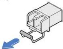
3 Gently pull on the extraction lever to withdraw the SFP module from the slot.
4 If the SFP module and/or fiber optic connector will remain unused for any period of time, be sure to fit the protective inserts to keep the optical interfaces clean.

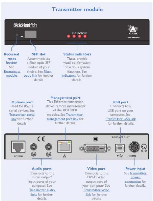
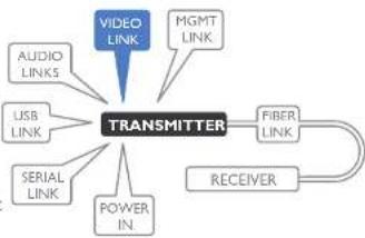
Transmitter video link
AdderLink XD150FX can support various high resolution video modes via the Dual-Link DVI-D port, see Video resolutions below for details.
To connect the video port
Connect the supplied digital video (plus USB) link cable between the DVI-D socket on the transmitter module rear panel and the DVI-D video output socket of the host computer.
flowchart
graph TD
    A["VIDEO LINK"] --> B["TRANSMITTER"]
    C["AUDIO LINKS"] --> B
    D["USB LINK"] --> B
    E["SERIAL LINK"] --> B
    F["POWER IN."] --> B
    G["MGMT LINK"] --> B
    H["FIBER LINK"] --> B
    I["RECEIVER"] --> B

Video resolutions
The XD150FX supports, but is not limited to, the following common video resolutions:
$$ 1 9 2 0 \times 1 0 8 0 (\mathrm{HD}) $$
$$ 1 9 2 0 \times 1 2 0 0 (\text { WUXGA }) $$
$$ 2 5 6 0 \times 1 0 8 0 $$
$$ 2 5 6 0 \times 1 4 4 0 (\text { WQHD }) $$
$$ 2 5 6 0 \times 1 6 0 0 (W Q X G A) $$
$$ 2 5 6 0 \times 2 0 4 8 (\text { Q S X G A }) $$
$$ 2 0 4 8 \times 2 1 6 0 $$
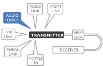
Transmitter audio links
The AdderLink XD150FX modules support stereo audio in and out connections. Where necessary, make connections between the audio input and/or output ports of the host computer and the transmitter module.
To connect the audio ports
For the line in and/or line out ports, connect the supplied audio link cable between the audio port on the transmitter module rear panel and the line in or line out socket of the host computer.
flowchart
graph TD
    A["TRANSMITTER"] --> B["VIDEO LINK"]
    A --> C["MGMT LINK"]
    A --> D["USB LINK"]
    A --> E["SERIAL LINK"]
    A --> F["POWER IN"]
    A --> G["FIBER LINK"]
    G --> H["RECEIVER"]
    I["AUDIO LINKS"] --> A

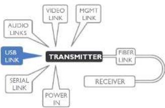
Transmitter USB link
The transmitter module requires a single USB connection to the host computer; this allows the receiver module to operate as a USB 2.0 hub with four ports.
To connect the USB port
Connect the type B connector of the supplied USB/video cable to the USB port on the rear panel of the transmitter module.
flowchart
graph TD
    A["USB LINK"] --> B["TRANSMITTER"]
    C["SERIAL LINK"] --> B
    D["AUDIO LINKS"] --> B
    E["VIDEO LINK"] --> B
    F["MGMT LINK"] --> B
    G["POWER IN"] --> B
    H["FIBER LINK"] --> I["RECEIVER"]
    B --> I
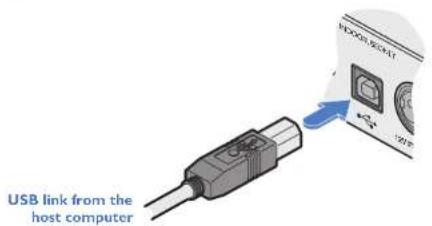
2 Connect the type A connector of the cable to a vacant USB port on the host computer.
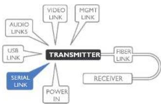
Transmitter serial link
The Options port provides an RS232 serial connection with the receiver module. When serial devices are attached to the Options ports on the transmitter and receiver modules, the units transparently convey the signals between them, via the fiber optic link, at rates up to 115200 baud - no serial configuration is required. An optional serial cable (part number: VSC45) is available from Adder.
flowchart
graph TD
    A["TRANSMITTER"] --> B["FIBER LINK"]
    A --> C["RECEIVER"]
    A --> D["POWER IN"]
    A --> E["USB LINK"]
    A --> F["AUDIO LINKS"]
    A --> G["VIDEO LINK"]
    A --> H["MGMT LINK"]
    A --> I["SERIAL LINK"]
To connect the serial port
I Use the optional serial cable (VSC45) to link the Options port on the rear panel of the transmitter module with a vacant RS232 serial port on your host computer.

Please see Appendix I for pin-out details of the Options port.
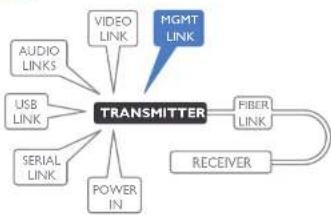
Transmitter management port link
The management port, located on the transmitter, allows the module to be connected to a standard Ethernet 10/100 network in order to allow remote monitoring and management functions to take place.
To connect the management port Connect a standard CATx patch lead between the port on the rear panel of the transmitter module and a standard network switch.
flowchart
graph TD
    A["TRANSMITTER"] --> B["FIBER LINK"]
    A --> C["RECEIVER"]
    A --> D["VIDEO LINK"]
    A --> E["USB LINK"]
    A --> F["SERIAL LINK"]
    A --> G["AUDIO LINKS"]
    A --> H["POWER IN"]
    A --> I["MGMT LINK"]

By default, the IP address is set to 192.168.1.22. If required, you can change the default IP address or alternatively, choose automated address selection by DHCP server. For details, please see the Configuration section.

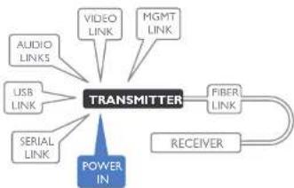
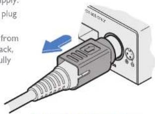
Transmitter power connection
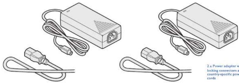
There is no on/off switch on either of the AdderLink XD150FX modules, so operation begins as soon as power is applied. The power adapters supplied with the modules use locking-type plugs to help prevent accidental disconnections; please follow the instructions shown on the right whenever disconnecting a power adapter.
flowchart
graph TD
    A["POWER IN"] --> B["TRANSMITTER"]
    B --> C["FIBER LINK"]
    B --> D["RECEIVER"]
    B --> E["VIDEO LINK"]
    B --> F["MGMT LINK"]
    B --> G["USB LINK"]
    B --> H["AUDIO LINKS"]
To connect the power adapter
1 Attach the output plug of the supplied power adapter to the power input socket on the right side of the rear panel.

2 Connect the IEC connector of the supplied country-specific power cord to the socket of the power adapter.
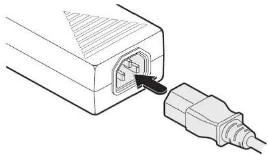
natural_image
Line drawing of an electrical plug inserted into a socket (no text or symbols)3 Connect the power cord to a nearby mains supply socket.
To disconnect the power adapter
I Isolate the power adapter from the mains supply.
2 Grasp the outer body of the power adapter plug where it connects with the module.
3 Gently pull the body of the outer plug away from the module. As the body of the plug slides back, it will release from the socket and you can fully withdraw the whole plug.
natural_image
Close-up of a plug adapter with a blue arrow indicating insertion (no text or symbols visible)Gently pull back the plug outer body to release the lock
IMPORTANT: Please read and adhere to the electrical safety information given within the Safety information section of this guide. In particular, do not use an unearthed power socket or extension cable.
Note: Both the modules and the power supplies generate heat when in operation and will become warm to the touch. Do not enclose them or place them in locations where air cannot circulate to cool the equipment. Do not operate the equipment in ambient temperatures exceeding 40 degrees Centigrade. Do not place the products in contact with equipment whose surface temperature exceeds 40 degrees Centigrade.
Receiver video display
A Dual-Link DVI-D port is provided on the rear panel of the receiver module. AdderLink XD150FX can support various high resolution video modes, see Video resolutions for details.
To connect the video display
Connect the DVI-D video cable from your video display to the video output port on the rear panel of the receiver module.
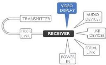
flowchart
graph TD
    A["TRANSMITTER"] --> B["FIBER LINK"]
    C["VIDEO DISPLAY"] --> D["RECEIVER"]
    E["AUDIO DEVICES"] --> D
    F["USB DEVICES"] --> D
    G["SERIAL LINK"] --> D
    H["POWER IN"] --> D
EDID management
The EDID (Extended Display Identification Data) is read from the connected video display at the receiver module; it is then transferred to, and stored within, the transmitter module and then declared to the host computer. If the video display is removed then the cloned EDID stored at the transmitter module will still be presented to the video source.
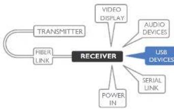
Receiver audio devices
The AdderLink XD150FX receiver module can support multiple audio devices, such as stereo headphones, a mono microphone or line-level in/out connections.
To connect audio devices
Connect stereo headphones and/or a mono microphone to the 3.5mm jack audio sockets on the front panel of the receiver module.
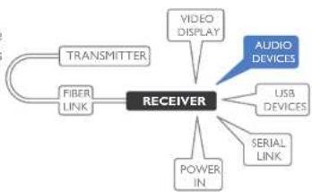
flowchart
graph TD
    A["TRANSMITTER"] --> B["FIBER LINK"]
    B --> C["RECEIVER"]
    C --> D["VIDEO DISPLAY"]
    C --> E["USB DEVICES"]
    C --> F["SERIAL LINK"]
    C --> G["AUDIO DEVICES"]
    C --> H["POWER IN"]
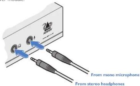
- Optionally use the rear panel 3.5mm jack audio sockets to connect line-level in or out connections from audio devices, such as powered speakers.

Note: If the microphone port on the front panel is used, the module will disconnect the Line In port on the rear panel.
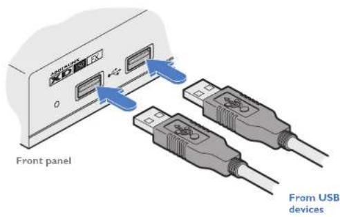
Receiver USB devices
The receiver module contains a USB hub that can support up to four v2.0 or v1.1 USB devices (in any combination). All four USB sockets are identical in operation.
flowchart
graph TD
    A["TRANSMITTER"] --> B["RECEIVER"]
    C["FIBER LINK"] --> B
    B --> D["VIDEO DISPLAY"]
    B --> E["AUDIO DEVICES"]
    B --> F["POWER IN"]
    B --> G["SERIAL LINK"]
    B --> H["USB DEVICES"]
To connect USB devices
Connect your USB keyboard, mouse and any other two USB devices to the four sockets distributed on the front and rear panels of the receiver module.

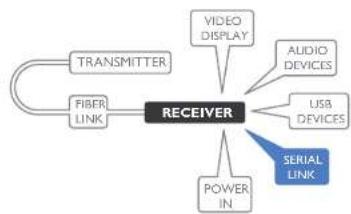
Receiver serial link
The Options port provides an RS232 serial connection with the transmitter module. When serial devices are attached to the Options ports on the transmitter and receiver modules, the units transparently convey the signals between them, via the fiber optic link, at rates up to 115200 baud - no serial configuration is required. An optional serial cable (part number: VSC45) is available from Adder.
flowchart
graph TD
    A["RECEIVER"] --> B["TRANSMITTER"]
    A --> C["FIBER LINK"]
    A --> D["VIDEO DISPLAY"]
    A --> E["AUDIO DEVICES"]
    A --> F["USB DEVICES"]
    A --> G["POWER IN"]
    A --> H["SERIAL LINK"]
To connect the serial port
I Use the optional serial cable (VSC45) to link the Options port on the rear panel of the receiver module with your RS232 serial device.

Please see Appendix 1 for pin-out details of the Options port.
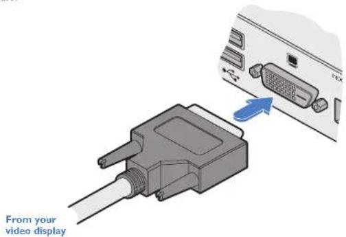
Receiver power connection
There is no on/off switch on either of the AdderLink XD150FX modules, so operation begins as soon as power is applied. The power adapters supplied with the modules use locking-type plugs to help prevent accidental disconnections; please follow the instructions shown on the right whenever disconnecting a power adapter.
flowchart
graph TD
    A["TRANSMITTER"] --> B["FIBER LINK"]
    B --> C["RECEIVER"]
    C --> D["VIDEO DISPLAY"]
    C --> E["AUDIO DEVICES"]
    C --> F["USB DEVICES"]
    C --> G["SERIAL LINK"]
    C --> H["POWER IN"]
To connect the power adapter
1 Attach the output plug of the supplied power adapter to the power input socket on the right side of the rear panel.

2 Connect the IEC connector of the supplied country-specific power cord to the socket of the power adapter.

natural_image
Line drawing of an electrical plug inserted into a box, showing internal socket and cable (no text or symbols)3 Connect the power cord to a nearby mains supply socket.
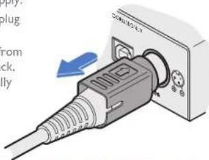
To disconnect the power adapter
I Isolate the power adapter from the mains supply.
2 Grasp the outer body of the power adapter plug where it connects with the module.
3 Gently pull the body of the outer plug away from the module. As the body of the plug slides back, it will release from the socket and you can fully withdraw the whole plug.
natural_image
Close-up of a plug adapter with a blue arrow indicating insertion (no text or symbols visible)Gently pull back the plug outer body to release the lock
IMPORTANT: Please read and adhere to the electrical safety information given within the Safety Information section of this guide. In particular, do not use an unearthed power socket or extension cable.
Note: Both the modules and the power supplies generate heat when in operation and will become warm to the touch. Do not enclose them or place them in locations where air cannot circulate to cool the equipment. Do not operate the equipment in ambient temperatures exceeding 40 degrees Centigrade. Do not place the products in contact with equipment whose surface temperature exceeds 40 degrees Centigrade.
Configuration
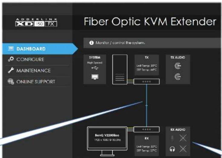
ACCESSING THE MANAGEMENT APPLICATION
AdderLink XD150FX modules generally configure themselves automatically, collecting EDID information from the attached monitor and passing it to the host computer. In most cases the modules will begin working together correctly as soon as they are connected. Where configuration changes are required (or remote monitoring is required), the management application provides an intuitive user interface.
To access the management application
I Use a computer that is directly or indirectly (i.e. via a network switch) connected to the XD150FX transmitter module. If you need to make a temporary connection, see right ☑
2 Run a web browser on your computer and enter the IP address of the transmitter module. By default, the IP address is set to 192.168.1.22. If required, you can change the default IP address or alternatively, choose automated address selection by DHCP server. See the Configure page.
3 If requested, enter the registered password to log on.
Note: The default user and password are 'admin' and 'password' respectively.
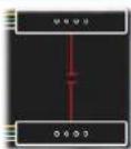
The Dashboard page should be displayed
The Dashboard page shows a real-time representation of the XD150FX installation.
Use the menu on the left side to display other pages.
Use the Online Support option to make contact with Adder through the main website.
A lost fiber link is shown by a broken red line.
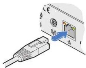
To temporarily connect a computer to the network port
If you need to make a temporary connection for configuration purposes, use a standard patch cable (cross-over or straight connections are both supported) to link the Ethernet 10/100 network port (on the rear panel of the XDI50FX transmitter module to your computer's network port.
natural_image
Illustration of a USB cable connector with an attached port (no text or symbols visible)Temporary link from your computer
The appearance of the icons changes:
- White: Port is in use.
- Gray: Port not used.
- Gray with cross: Port is disabled.
The Configure page
The Configure page allows you to control the various peripheral feeds and also determine the network addressing details.
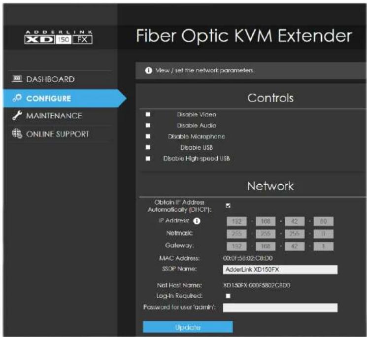
Controls
All peripheral feeds are enabled by default. However, this section allows each feed to be disabled as required.
- Disable High-speed USB - this option needs to be ticked when connecting to Adder CCS4-USB and/or CCS-PRO4 devices.
Network
- Obtain IP Address automatically (DHCP) - When ticked, the transmitter module will use the DHCP (Dynamic Host Configuration Protocol) to automatically determine all network settings. When DHCP is used, the next three options are not manually editable.
- IP Address - set the IP address for the module.
- Netmask - set a subnet mask to accompany the IP address.
• Gateway - optionally define a suitable address for a gateway device.
• MAC Address - displays the unique (and fixed) MAC address for the module. - SSDP Name - optionally add an identifier for this module.
- Log-in Required - when ticked, you will be requested to enter a user name and password.
- Password for user 'admin' - define a password here to be used when the 'Log In Required' option above is ticked.
Note: The default user name and password are 'admin' and 'password' respectively.
Once changes are made, click the Update button to apply them.
The Maintenance page
The Maintenance page contains numerous features used for monitoring, restarting and upgrading the modules.
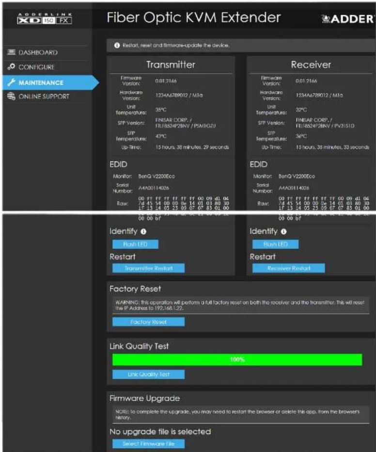
Transmitter and receiver details
These twin sections list numerous details for each module:
- Firmware, hardware and SFP (optical module) versions.
- Unit (main circuit board) and SFP (optical module) temperatures.
- Up-time.
- EDID - lists the currently registered video monitor, together with its serial number and a full raw hex listing of the declared EDID signature.
- Identify - Click the Flash LED button to flash the front panel indicators of the chosen module. Click once for five flashes, twice for indefinite flashing and a third time to stop the flashing.
- Restart - If a module becomes unresponsive, click the relevant Restart button to reboot the required module.
Factory Reset
Click this button to perform a full factory reset on both modules. All settings will be returned to their default values; the transmitter module will default to use the IP address of 192.168.1.22.
Link Quality Test
This section tests and displays the quality of the data link between the two modules.
Firmware Upgrade
Use this section to perform a firmware upgrade on both modules using files available on request from Adder technical support.
Note: Firmware upgrades must be performed in pairs, i.e. the transmitter and receiver together. If one of the modules is not connected, the upgrade will not be carried out.
Download the API description
Click here to view the API description in YAML format.
Operation
The AdderLink XD150FX modules are designed to be transparent in operation; all peripherals should respond exactly as they would when situated next to your host computer.
INDICATORS
The transmitter and receiver modules contain various indicators to provide you with status information. Both modules have four red indicators on their front panels.
Red status indicators
The red status indicators on the front panels of each module mostly behave in the same manner at the same time:

flowchart
graph TD
    A["PWRUS"] --> B["LNK"]
    A --> C["USB"]
    A --> D["VID"]
    A --> E["PWR"]
    B --> F["This indicator will be on once the link between the transmitter and receiver modules is established. Flashes to warn that a non-approved SFP module has been fitted."]
    C --> G["This indicator will be on once the USB extender and hub located within the receiver module have been successfully enumerated by the USB host on your computer. Flashes to indicate the USB system has entered suspend mode. Ensure that one or more USB devices are attached to the receiver module and a valid USB link is made between the transmitter module and the host computer."]
    D --> H["This indicator will be on (on both modules) when a valid video signal is detected."]
    E --> I["This indicator will be on when power is supplied to each module."]
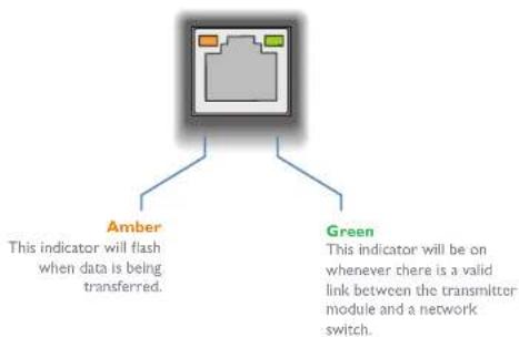
Green and amber status indicators (transmitter module only)
The green and amber status indicators on the network management port connector of the transmitter module (rear panel) provide further status information:
flowchart
graph TD
    A["Switch"] --> B["Amber"]
    A --> C["Green"]
    B --> D["This indicator will flash when data is being transferred."]
    C --> E["This indicator will be on whenever there is a valid link between the transmitter module and a network switch."]
RESETTING A MODULE
On the left side of the front panel of each module, you will find a small hole which is used to invoke special functions. Use a thin implement, such as a straightened paperclip to press and hold the button concealed behind the smaller hole. Depending on when you release the button, the module will either perform a normal reset or completely reset itself to factory defaults:
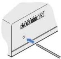
natural_image
Illustration of a device control panel with a blue arrow pointing to the left side (no text or symbols visible)| Time (seconds): 0 | 5 | 10 | 15 | |
| Indicator(s): | PWR: On | All: Alternate flashing | All: Rapid flashing together | All: Normal |
| Release button for: | Normal restart(not currently used) | Special configuration option | Reset to factory defaults | Return to normal operation |

Further information
This chapter contains a variety of information, including the following:
• Getting assistance - see right
- Appendix I - Options port pin-out
- Appendix 2 - Open source licenses
• Safety Information
- Warranty
• Radio frequency energy statements
GETTING ASSISTANCE
If you are still experiencing problems after checking the information contained within this guide, then we provide a number of other solutions:
• Online solutions and updates – www.adder.com/support
Check the Support section of the adder.com website for the latest solutions and firmware updates.
• Technical support – www.adder.com/contact-support-form
For technical support, use the contact form in the Support section of the adder.com website - your regional office will then get in contact with you.

APPENDIX I - OPTIONS PORT PIN-OUT
The OPTIONS port uses a 6p6c socket. The pin-out is listed below.
Note: Although the pin labeled 'Not used' is inactive, it is still connected internally and so no links should be made at all to this pin.

OPTIONS
Pin Signal Direction
1 CTSI / RXD2 Input to the module
2 RXDI Input to the module
3 TXDI Output from the module
4 RTS1 /TXD2 Output from the module
5 Not used
6 GND Reference for all signals

APPENDIX 2 - OPEN SOURCE LICENSES
This product includes binaries that are derived from the open source community.
[EMPTY]
IwIP is licenced under the BSD licence:
Copyright (c) 2001-2004 Swedish Institute of Computer Science.
All rights reserved.
Redistribution and use in source and binary forms, with or without modification, are permitted provided that the following conditions are met:
I. Redistributions of source code must retain the above copyright notice, this list of conditions and the following disclaimer.
2. Redistributions in binary form must reproduce the above copyright notice, this list of conditions and the following disclaimer in the documentation and/or other materials provided with the distribution.
3. The name of the author may not be used to endorse or promote products derived from this software without specific prior written permission.
THIS SOFTWARE IS PROVIDED BY THE AUTHOR "AS IS" AND ANY EXPRESS OR IMPLIED WARRANTIES, INCLUDING, BUT NOT LIMITED TO, THE IMPLIED WARRANTIES OF MERCHANTABILITY AND FITNESS FOR A PARTICULAR PURPOSE ARE DISCLAIMED. IN NO EVENT SHALL THE AUTHOR BE LIABLE FOR ANY DIRECT, INDIRECT, INCIDENTAL, SPECIAL, EXEMPLARY, OR CONSEQUENTIAL DAMAGES (INCLUDING, BUT NOT LIMITED TO, PROCUREMENT OF SUBSTITUTE GOODS OR SERVICES; LOSS OF USE, DATA, OR PROFITS; OR BUSINESS INTERRUPTION) HOWEVER CAUSED AND ON ANY THEORY OF LIABILITY, WHETHER IN CONTRACT, STRICT LIABILITY, OR TORT (INCLUDING NEGLIGENCE OR OTHERWISE) ARISING IN ANY WAY OUT OF THE USE OF THIS SOFTWARE, EVEN IF ADVISED OF THE POSSIBILITY OF SUCH DAMAGE.
[EMPTY]
jsmn is licenced under the MIT license:
Copyright (c) 2010 Serge A. Zaitsev
Permission is hereby granted, free of charge, to any person obtaining a copy of this software and associated documentation files (the "Software"), to deal in the Software without restriction, including without limitation the rights to use, copy, modify, merge, publish, distribute, sublicense, and/or sell copies of the Software, and to permit persons to whom the Software is furnished to do so, subject to the following conditions:
The above copyright notice and this permission notice shall be included in all copies or substantial portions of the Software.
THE SOFTWARE IS PROVIDED "AS IS", WITHOUT WARRANTY OF ANY KIND, EXPRESS OR IMPLIED, INCLUDING BUT NOT LIMITED TO THE WARRANTIES OF MERCHANTABILITY, FITNESS FOR A PARTICULAR PURPOSE AND NON-INFRINGEMENT. IN NO EVENT SHALL THE AUTHORS OR COPYRIGHT HOLDERS BE LIABLE FOR ANY CLAIM, DAMAGES OR OTHER LIABILITY, WHETHER IN AN ACTION OF CONTRACT, TORT OR OTHERWISE, ARISING FROM, OUT OF OR IN CONNECTION WITH THE SOFTWARE OR THE USE OR OTHER DEALINGS IN THE SOFTWARE.

SAFETY INFORMATION
- For use in dry, oil free indoor environments only.
- Warning - live parts contained within power adapter(s).
- No user serviceable parts within power adapter(s) - do not dismantle.
- Plug the power adapter(s) into socket outlets close to the module that they are powering.
- Do not use an unearthed power socket or extension cable.
- Do not use a power adapter if its case becomes damaged, cracked or broken or if you suspect that it is not operating properly.
- Replace the power adapter(s) with a manufacturer approved type only.
- If you use a power extension cord with the module, make sure the total ampere rating of the devices plugged into the extension cord does not exceed the cord's ampere rating. Also, make sure that the total ampere rating of all the devices plugged into the wall outlet does not exceed the wall outlet's ampere rating.
- Do not attempt to service the modules yourself.
WARRANTY
Adder Technology Ltd warrants that this product shall be free from defects in workmanship and materials for a period of two years from the date of original purchase. If the product should fail to operate correctly in normal use during the warranty period, Adder will replace or repair it free of charge. No liability can be accepted for damage due to misuse or circumstances outside Adder's control. Also Adder will not be responsible for any loss, damage or injury arising directly or indirectly from the use of this product. Adder's total liability under the terms of this warranty shall in all circumstances be limited to the replacement value of this product.
If any difficulty is experienced in the installation or use of this product that you are unable to resolve, please see the Getting assistance section.
RADIO FREQUENCY ENERGY
All cables used with this equipment must be shielded in order to maintain compliance with radio frequency energy emission regulations and ensure a suitably high level of immunity to electromagnetic disturbances.
European EMC directive 2014/30/EU
This equipment has been tested and found to comply with the limits for a class A computing device in accordance with the specifications in the European standard EN55032. These limits are designed to provide reasonable protection against harmful interference. This equipment generates, uses and can radiate radio frequency energy and if not installed and used in accordance with the instructions may cause harmful interference to radio or television reception. However, there is no guarantee that harmful interference will not occur in a particular installation. If this equipment does cause interference to radio or television reception, which can be determined by turning the equipment on and off, the user is encouraged to correct the interference with one or more of the following measures: (a) Reorient or relocate the receiving antenna. (b) Increase the separation between the equipment and the receiver. (c) Connect the equipment to an outlet on a circuit different from that to which the receiver is connected. (d) Consult the supplier or an experienced radio/TV technician for help.
FCC Compliance Statement (United States)
This equipment generates, uses and can radiate radio frequency energy and if not installed and used properly, that is, in strict accordance with the manufacturer's instructions, may cause interference to radio communication. It has been tested and found to comply with the limits for a class A computing device in accordance with the specifications in Subpart J of part 15 of FCC rules, which are designed to provide reasonable protection against such interference when the equipment is operated in a commercial environment. Operation of this equipment in a residential area may cause interference, in which case the user at his own expense will be required to take whatever measures may be necessary to correct the interference. Changes or modifications not expressly approved by the manufacturer could void the user's authority to operate the equipment.
Canadian Department of Communications RFI statement
This equipment does not exceed the class A limits for radio noise emissions from digital apparatus set out in the radio interference regulations of the Canadian Department of Communications.
Contact: www.adder.com/contact-details
Support: www.adder.com/support
Documentation by:

www.ctxd.com
© 2018 Adder Technology Limited
All trademarks are acknowledged.
Part No. MAN-XD150FX-ADDER • Release 1.2

Index
A
Audio receiver 12 transmitter 8
C
CCS4-USB 16
CCS-PRO4 16
Connections overview 6
D
DDX Matrix accessing 15 Default mode 19 DHCP 16 Disable High-speed USB 16
E
EDID management 12
F
Firmware upgrade 17
G
Gateway 16
1
Indicators 18 IP Address 16
M
MAC Address 16
N
Net Mask 16 Network port temporary connection 15
P
Power receiver 14 transmitter 11
R
Reset button 3 Resetting 19 RS232 9.13
S
Safety Information 23 Serial port receiver 13 transmitter 9
U
USB receiver 13
V
Video receiver 12 transmitter 8
W
Warranty 23

- Installation
- Configuration
- Operation
- Further information
- Index
- Introduction
- WELCOME
- Transmission distances
- Receiver
- ADDERLINK XDI50FX FEATURES
- LOCATIONS
- CONNECTIONS
- Fiber optic link
- To make the fiber optic link
- To remove an SFP module
- Transmitter video link
- To connect the video port
- Video resolutions
- Transmitter audio links
- To connect the audio ports
- Transmitter USB link
- To connect the USB port
- Transmitter serial link
- To connect the serial port
- Transmitter management port link
- Transmitter power connection
- To connect the power adapter
- To disconnect the power adapter
- IMPORTANT: Please read and adhere to the electrical safety information given within the Safety information section of this guide. In particular, do not use an unearthed power socket or extension cable.
- Receiver video display
- To connect the video display
- EDID management
- Receiver audio devices
- To connect audio devices
- Receiver USB devices
- To connect USB devices
- Receiver serial link
- Receiver power connection
- ACCESSING THE MANAGEMENT APPLICATION
- To access the management application
- To temporarily connect a computer to the network port
- The Configure page
- Controls
- Network
- The Maintenance page
- Transmitter and receiver details
- Factory Reset
- Link Quality Test
- Firmware Upgrade
- Download the API description
- INDICATORS
- Red status indicators
- Green and amber status indicators (transmitter module only)
- RESETTING A MODULE
- GETTING ASSISTANCE
- APPENDIX I - OPTIONS PORT PIN-OUT
- APPENDIX 2 - OPEN SOURCE LICENSES
- SAFETY INFORMATION
- WARRANTY
- RADIO FREQUENCY ENERGY
- European EMC directive 2014/30/EU
- FCC Compliance Statement (United States)
- Canadian Department of Communications RFI statement
- A
- C
- D
- E
- F
- G
- 1
- M
- N
- P
- R
- S
- U
- V
- W
Brand : Adder
Model : XD150FX-SM
Category : AV Switch