
RH10UC - Audio/Video Equipment AJA - Free user manual and instructions
Find the device manual for free RH10UC AJA in PDF.

| Product Type | R-Series Card Module (SD to HD Upconverter/HD Framesync) |
| Brand | AJA |
| Model | RH10UC |
| Input Formats | 525/59.94, 625/50 (SMPTE 259M SDI) |
| Output Formats | 1080i 50/59.94, 720p 59.94 Hz (HD-SDI SMPTE 292M) |
| Power Consumption | 7 Watts |
| Video Processing | 10-bit, motion adaptive interpolation, multi-point horizontal and vertical filters |
| Aspect Ratio Conversion | 4:3 pillar box, 14:9 pillar box, full screen, letterbox, wide zoom |
| User Interface | Two toggle switches (Parameter Select and Parameter Adjust), 4-character alphanumeric display |
| Reference Input | Bi-level/tri-level sync genlock, 2 BNC looping, frame reference option |
| Audio Support | 8 channels embedded SDI audio in Upconvert mode |
| Compliance | FCC Class A, CE, ICES-003, VCCI Class A, KCC Class A, BSMI Class A |
| Warranty | 5 years from date of purchase |
| Dimensions | Fits AJA FR1 or FR2 frame (1 slot) |
| Weight | Approx. 0.5 kg (estimate) |
| Cleaning | Use dry cloth only; do not use near water |
Frequently Asked Questions - RH10UC AJA
User questions about RH10UC AJA
0 question about this device. Answer the ones you know or ask your own.
Ask a new question about this device
Download the instructions for your Audio/Video Equipment in PDF format for free! Find your manual RH10UC - AJA and take your electronic device back in hand. On this page are published all the documents necessary for the use of your device. RH10UC by AJA.
USER MANUAL RH10UC AJA
SD to HD Upconverter
R-series Card Module
Published: 7/13/10
Installation and Operation Guide
Trademarks
AJA® , KONA®, Ki Pro®, and XENA® are registered trademarks of AJA Video, Inc. FiDO™, Io HD™ and Io™ are trademarks of AJA Video, Inc. HDMI, the HDMI logo and High-Definition Multimedia Interface are trademarks or registered trademarks of HDMI Licensing LLC. DVI is a registered trademark of DDWG. All other trademarks are the property of their respective holders.
Notice
Copyright © 2010 AJA Video, Inc. All rights reserved. All information in this manual is subject to change without notice. No part of the document may be reproduced or transmitted in any form, or by any means, electronic or mechanical, including photocopying or recording, without the express written permission of AJA Inc.
Contacting Support
To contact AJA Video for sales or support, use any of the following methods:
180 Litton Drive, Grass Valley, CA. 95945 USA
Telephone: 800.251.4224 or 530.274.2048
Fax: 530.274.9442
Web: http://www.aja.com
Support Email: support@aja.com
Sales Email: sales@aja.com
When calling for support, have all information at hand prior to calling.
Limited Warranty
AJA Video warrants that this product will be free from defects in materials and workmanship for a period of five years from the date of purchase. If a product proves to be defective during this warranty period, AJA Video, at its option, will either repair the defective product without charge for parts and labor, or will provide a replacement in exchange for the defective product.
In order to obtain service under this warranty, you the Customer, must notify AJA Video of the defect before the expiration of the warranty period and make suitable arrangements for the performance of service. The Customer shall be responsible for packaging and shipping the defective product to a designated service center nominated by AJA Video, with shipping charges prepaid. AJA Video shall pay for the return of the product to the Customer if the shipment is to a location within the country in which the AJA Video service center is located. Customer shall be responsible for paying all shipping charges, insurance, duties, taxes, and any other charges for products returned to any other locations.
This warranty shall not apply to any defect, failure or damage caused by improper use or improper or inadequate maintenance and care. AJA Video shall not be obligated to furnish service under this warranty a) to repair damage resulting from attempts by personnel other than AJA Video representatives to install, repair or service the product, b) to repair damage resulting from improper use or connection to incompatible equipment, c) to repair any damage or malfunction caused by the use of non-AJA Video parts or supplies, or d) to service a product that has been modified or integrated with other products when the effect of such a modification or integration increases the time or difficulty of servicing the product.
THIS WARRANTY IS GIVEN BY AJA VIDEO IN LIEU OF ANY OTHER WARRANTIES, EXPRESS OR IMPLIED. AJA VIDEO AND ITS VENDORS DISCLAIM ANY IMPLIED WARRANTIES OF MERCHANTABILITY OR FITNESS FOR A PARTICULAR PURPOSE. AJA VIDEO'S RESPONSIBILITY TO REPAIR OR REPLACE DEFECTIVE PRODUCTS IS THE WHOLE AND EXCLUSIVE REMEDY PROVIDED TO THE CUSTOMER FOR ANY INDIRECT, SPECIAL, INCIDENTAL OR CONSEQUENTIAL DAMAGES IRRESPECTIVE OF WHETHER AJA VIDEO OR THE VENDOR HAS ADVANCE NOTICE OF THE POSSIBILITY OF SUCH DAMAGES.
Features
• Full 10-bit broadcast quality SD to HD upconverter mode of operation
• HD Framesync mode of operation
• 8/10 bit SMPTE 259 SDI input, 2 re-clocked outputs
• 8/10 bit SMPTE 292 HD-SDI output, 4 outputs
- 8 Channels of Embedded SDI Audio are supported in Upconvert mode (audio is not supported in HD Framesync mode)
- bi/tri-level sync genlock input, 2 BNC loop-through with adjustable output timing
• 4:3 or 16:9 SD inputs
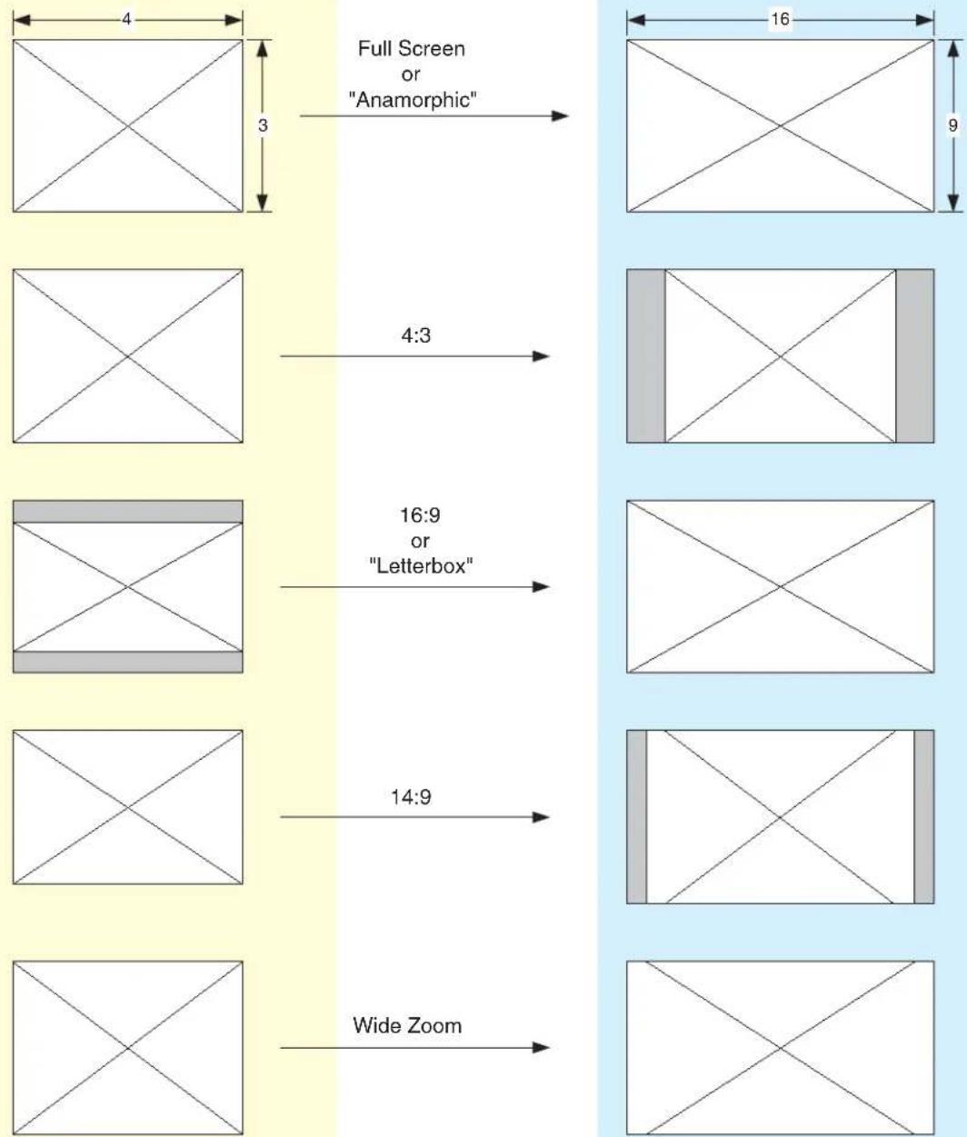
- 4:3 to 16:9 conversion modes:
4:3 pillar box (4:3 image in center of screen, black sidebars)
14:9 pillar box (4:3 image zoomed to fill a 14:9 image, black sidebars)
Full Screen (for anamorphic inputs)
Letterbox (input 16:9 letterbox is zoomed to full screen)
Widezoom (a combination of zoom and horizontal stretch to fill 16:9 screen; will introduce a small aspect ratio error)
- Separate multipoint H and V filters
- Motion adaptive interpolation
• 16 bit coefficients, 16 bit internal data paths
- Accurate 16 bit SD to HD colorspace conversion
• 1 slot AJA FR1 or FR2 frame
Upconverter Specifications
Table 1.
| Item Specification | |
| Input SDI (525 or 625) in Up | convert ModeHD SDI (1080i or 720p) in HD Framesync Mode |
| Output HD SDI (1080i or 720p) | |
| Delay 1 Frame. Audio is delayed to compensate for the delay through the video path. | |
| Power 7 Watts | |
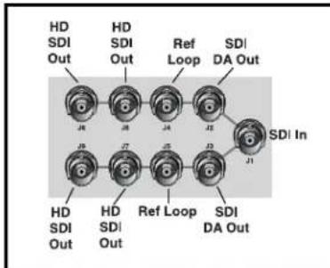
I/O Connections
flowchart
graph TD
    A["HD SDI Out"] --> B["26"]
    C["HD SDI Out"] --> D["28"]
    E["Ref Loop"] --> F["24"]
    G["SDI DA Out"] --> H["35"]
    I["SDI In"] --> J["31"]
    K["HD SDI Out"] --> L["29"]
    M["HD SDI Out"] --> N["27"]
    O["Ref Loop"] --> P["25"]
    Q["SDI DA Out"] --> R["33"]
FR1 Frame Layout RH10UC Rear Panel

FR2 Frame Layout RH10UC Rear Panel
FR1 and FR2 BNC Connector Assignments, RH10UC Card Module
When the RH10UC module is installed in an AJA FR1 or FR2 frame, a corresponding group of 9 BNCs on the rear panel then provide I/O for the module. The illustration above shows the connector assignments for both the FR1 and FR2 when used with the RH10UC.
Installation
Typically, RH10UC installation consists of the following:
- disconnect power from the frame (remove line cord)
- remove the FR1/FR2 front panel
- install RH10UC card module
- replace the FR1/FR2 front panel
- apply power to the frame by connecting a north american-style power cord from the frame to mains power (90 to 260 VAC)

Warning!
Ensure Mains Power is disconnected before installing the FR1 or FR2 frame R-series modules into the frame, or installing and removing options. If a Mains switch is not provided, the power cord(s) of this equipment provide the means of disconnection. The socket outlet must be installed near the equipment and must be easily accessible.

Warning!
FR2 Dual Power Cord Notice—please read this. To reduce the risk of electrical shock, disconnect both power cords before servicing equipment.

Caution!
The FR1/FR2 front fan door is heavy and is not hinged. Remove with Caution.
Instructions for removing the frame front door for module installation is discussed in the FR1/FR2 User Manual.
User Controls
The user interface for the RH10UC consists of two toggle switches and a 4-character alphanumeric display. See the photo "RH10UC User Interface Controls" that follows for control location and function.
The Parameter Select (PS) switch selects a parameter for adjustment and viewing on the display. Once a desired parameter is selected by moving the PS switch, you then use the other switch—called Parameter Adjust (PA)—to make a change to the parameter setting. Both switches are toggle switches that can be pushed to the right or left, allowing you to move forward or backward through available choices. After actuation, either switch will return to a middle position.
If you move a switch and hold it in place (left or right), the RH10UC will sense this and auto-increment or decrement.
By default, the 4-character display shows the current status of the RH10UC—referred to as status mode. When you're adjusting parameters or settings, the display changes from status mode to adjust mode to show the new value settings or parameters. After a period of inactivity the display always reverts to status mode.

RH10UC User Interface Controls
Normal Operation Status Mode
The RH10UC display by default will show you which inputs are present, any detected error conditions, and the functional mode the board is in (upconverting, downconverting, HD/SD framesync, etc.). After the board is powered on, it enters status mode and stays there until a toggle switch is selected and you enter adjust mode. After 5 seconds of inactivity in adjust mode, it then returns to status mode.
While in status mode, the 4-character display indicates the following:
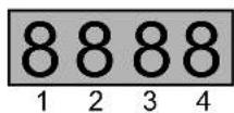
Table 2.
| Character # Indicates | |
| 1 $—Standard Definition (SD) input signal presentE—Error on input signalH—High definition signal present (HD Framesync mode only) | |
| 2 Blank—not used | |
| 3 or 4 Mode Mnemonic: these codes show what the board is doingUP—up convertHF—High Definition Framesync |
Editing and Viewing Board Settings Adjust Mode
Moving the PS switch in either direction causes the RH10UC to enter adjust mode. When this happens, the display will change to indicate the parameter being shown/edited.
Table 3.
| Character # Indicates | |
| 1 | Normally displays parameter number 0 through 9, and A to Z(some numbers and letters are currently not used—only those used will be discussed in this document).If the parameter value (see below) exceeds 3-digits, this display character will also be used so 4-digits of the value can be viewed. |
| 1 to 4 A | 1 to 4-character code that indicates a parameter value.Usually the value will be shown in characters 2 through 4, except when the value requires all 4 characters. |
When a parameter is shown in adjust mode, the last selected parameter is shown in character 1 and the current parameter value is shown in characters 2 through 4—if the value exceeds 3 digits, then all 4 characters in the display are used to show the value. Parameter choices and their definitions are listed in a table on the following page.
Selecting Parameters
Move the PS switch to the left to increment the parameter number or move it to the right to decrement the parameter number. Characters 2 through 4 will change to reflect the settings of these parameters as they are incremented/decremented.
Editing Parameters
When a parameter has been selected with the PS switch, use the PA switch to then change the parameter value (as displayed by characters 2 through 4) to another value. Like the PS switch, you'll move PA switch to the left or
right to scroll through the setting choices. When a desired choice is found, simply leave it at that choice to select it.
Changing Operating Modes
Changing the selection in Param 0 from "UP" to "HF" selects the operating mode of the board and results in alternate sets of parameters and definitions. The two tables that follow show the parameter choices and definitions available when the board is in Upconvert or HD Framesync mode. Making a change in Param 0 results in an alternate bitfile to be loaded and the HD Framesync H and V output timing params to be loaded into the registers. During the bitfile loading process you may notice a short delay when the switches are not responsive. After the process completes, the unit will return to the status display.
In the Status display, which is active when the unit's switches have not been toggled for 5 seconds or more, an "H" will appear in the character 1 position if the unit is in HD Framesync mode—and there is a valid HD signal present on both the video input and the genlock input (the two must match).
Parameter Choices and Definitions When in Upconvert Mode
Table 4.
| Parameter (Character 1) | Definitions (Choices are shown in italics) |
| 0 | Selects a Mode of operation for the board. Choices are: UP—up convert HF—high definition framesync |
| 1 | Output Format. Choices are: li—1080i 59.94Hz 7p—720p 59.94Hz A—automatic; output follows the tri-sync input (default) |
| 2 | Upconvert Mode. Choices are: 43—4x3 pillar box format 14—14x9 pillar box format (default) FS—full-screen (anamorphic display) format LB—16x9 letterbox input to full WZ—wide zoom format |
| 5 | Output Timing Mode, Set Reference Source. Choices are: R—reference input I—video input F—free run (default) |
| 6 | ON—allows VITC timecode and Closed Caption (CC) information to be passed on lines 20 and 21. OFF—lines 20 and 21 are blanked (default). |
Table 4.
| Parameter (Character 1) | Definitions (Choices are shown in italics) |
| 7 | Freeze VideoON—Freezes the output video.OFF—Not Frozen (default). |
| 8 | Generate test pattern:ON—75% color barsOFF—none (default) |
| 9 | ON—Sharp Vertical Filter. Results in sharper image, with increased edge artifacts.OFF—Standard Vertical Filter (default). Provides the best possible image, although edges are not as sharp. |
| A | Display SD Input Format, possible values are:A—No input detectedAERR—Input error detectedA525—SD 525A625—SD 625 |
| H | Output Timing Adjust—HorizontalThe maximum range changes based on the output frame rate and the frame geometry. Switch adjusts value by pixels to shift horizontally.The factory defaults are zero-timed values as measured empirically at AJA. They are given in the table below.The RH10UC remembers H and stores it in flash, recalling it as needed when the output frame rate or geometry changes.Refer to the H and V Parameter Reference Table appearing later in this manual for value ranges. |
| V | Output Timing Adjust—VerticalThe maximum range changes based on the output frame rate and the frame geometry. Switch adjusts value by lines in frame.V delays are signed numbers, with zero timing relative to the reference signal noted as zero (“0”). Zero is the factory default for both V timing parameters.The RH10UC remembers V and stores it in flash, recalling it as needed when the output frame rate or geometry changes.Refer to the H and V Parameter Reference Table that follows for ranges. |
| I | Information—shows current software version |
| W | Set RH10UC To Factory DefaultsTo set all values to factory defaults, select Param W, and move the adjust switch to the right. This will set all parameters in the system to factory values. After a 5 second inactivity time-out, the values will be written to flash.If all the values in the system match the factory defaults, either through adjustment or by setting them as above, the display for param W will be “WFAC”. If any of the values are different, the display for param W will simply be “W”. |
Parameter Choices and Definitions When in HD Framesync mode
Table 5.
| Parameter (Character 1) | Definitions (Choices are shown in italics) |
| 0 | Selects a Mode of operation for the board. Choices are:UP—up convertHF—high definition framesync |
| 5 | Output Timing Mode, Set Reference Source. Choices are:R—reference inputI—video inputF—free run (default) |
| 7 | Freeze VideoON—Freezes the output video.OFF—Not Frozen (default). |
| A | Display HD Input Format, possible values are:A—No input detectedAERR—Input error detectedA1p2—HD1080psf 23.98A1i6—HD 1080i 59.94 or 1080i 60A1i5—HD 1080i 50A7p6—HD 720p 59.94 or 720p 60 |
| V | Output Timing Adjust—VerticalThe maximum range changes based on the output frame rate and the frame geometry. Switch adjusts value by lines in frame.V delays are signed numbers, with zero timing relative to the reference signal noted as zero (“0”). Zero is the factory default for both V timing parameters.The RH10UC remembers V and stores it in flash, recalling it as needed when the output frame rate or geometry changes.Refer to the H and V Parameter Reference Table that follows for ranges. |
| H | Output Timing Adjust—HorizontalThe maximum range changes based on the output frame rate and the frame geometry. Switch adjusts value by pixels to shift horizontally.The factory defaults are zero-timed values as measured empirically at AJA. They are given in the table below.The RH10UC remembers H and stores it in flash, recalling it as needed when the output frame rate or geometry changes.Refer to the H and V Parameter Reference Table that follows for ranges. |
| I | Information—shows current software version |
Table 5.
| Parameter (Character 1) | Definitions (Choices are shown in italics) |
| W Set RH10UC To Factory DefaultsTo set all values to factory defaults, select Param W, and move the adjust switch to the right. This will set all parameters in the system to factory values. After a 5 second inactivity time-out, the values will be written to flash.If all the values in the system match the factory defaults, either through adjustment or by setting them as above, the display for param W will be “WFAC”. If any of the values are different, the display for param W will simply be “W”. | |
H and V Parameter Reference Table For Upconvert Mode
| Output Geometry @ FR | Min V Delay | Zero-timedV Delay | Max V Delay Min H Delay | Zero-timed H Delay | Max H Delay |
| 1080i @ 29.97 Hz -999 0 562 0 1877 2199 | |||||
| 1080i @ 25 Hz -999 0 562 0 2014 2639 | |||||
| 720p @ 59.94 Hz -749 0 740 0 1304 1649 | |||||
| 720p @ 50 Hz -749 0 740 0 1304 1649 | |||||
H and V Parameter Reference Table For HD Framesync Mode
| Output Geometry @ FR | Min V Delay | Zero-timed V Delay | Max V Delay MIn H Delay | Zero-timed H Delay | Max H Delay | |
| 1080i @ 29.97 Hz -999 0 5 0 2134 2199 | ||||||
| 1080i @ 25 Hz -999 0 5 0 68 | 2639 | |||||
| 1080psf @ 23.98 Hz | -999 0 5 0 2134 2749 | |||||
| 720p @ 59.94 Hz -749 0 | 5 | 0 | 0 | 1 | 6 | |
| 720p @ 50 Hz -749 0 5 0 1100 | 1979 | |||||
External Reference Information
The RH10UC expects the External Reference to be an HD Tri-level sync signal. The Reference must be consistent with the Output Format selection. If the Output Format selection is "A" for automatic - the RH10UC will detect the format of the Tri-level sync input and set the Output Format to the detected format. If no reference is provided, the RH10UC will lock to the input video.
The External Reference input can come from two different sources on the RH10UC. There are jumpers on the RH10UC (see figure below) for selecting the external reference source and for optionally terminating the selected reference source.
Looping Reference
The RH10UC cell group of 9 BNCs contains two BNCs that can be used for a looping reference connection. If this method is used, then the reference select setting on the RH10UC should be set to "LOOP" and the TERMINATION setting should be set to "OFF" (no termination). Optionally, if you're using only one of the looping reference BNCs, then the TERMINATION setting should be set to "ON."
Frame Reference
Alternatively, the RH10UC installed in a FR1 or FR2 frame can use the frame's frame reference input BNC connector, which feeds an external reference video signal to all modules installed in the frame. How the signal is distributed differs for the FR1 and FR2 frames. Additionally, individual modules can usually be strapped as to whether external reference is distributed from the frame or directly to BNCs on the module's corresponding cell group (the 9 BNCs on the rear panel).
FR1 Frame: the external reference signal is distributed passively to all frame modules. If you wish to use the frame reference, the RH10UC should have "FRAME" reference selected on the module strapping, and one and only one card in the frame should have "TERMINATION" set to "ON." All other cards in the frame should have TERMINATION set to "OFF."
FR2 Frame: the external reference signal is distributed by an in-frame distribution amplifier to all frame modules. This system terminates the Frame Reference input BNC and buffers the signal to all slots. If using frame reference, the RH10UC installed in the FR2 frame should have "FRAME" set for reference select, and all cards should have TERMINATION set to "OFF."
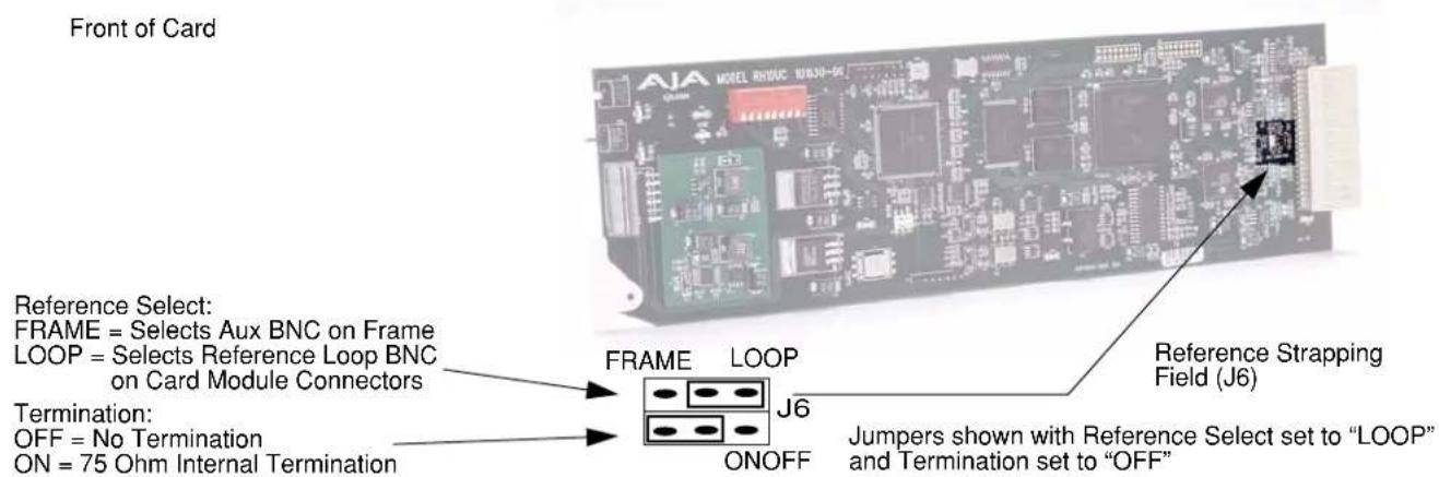
Reference Select and Termination Configuration
RH10UC Aspect Ratio Modes
4:3 Upconverts To These displays on 16:9
Specifications
| Item Specification | |
| Input Formats 525/59.94, 625/50, | SMPTE 259M |
| Output Formats 1080i 50/59.94, | 720p 59.94 Hz (50Hz output requires 50 Hz input) |
| Upconversion Motion adaptive, | Multi-point interpolation, 10-bit processing |
| Inputs | SDI, BNC |
| Reference 2 x BNC, looping | |
| Outputs Input Loop, 2 x BNC, Equalized HD-SDI, 4 x BNC | |
| User Controls Mode: Upconvert, | Frame Synchronizer, Output Format, Aspect Ratio Convert Select, and Output Timing |
| Size: Fits AJA R-Series Frames | Compatible With Leitch® 6800 Series Frames |
| Power Consumption: 6 watts | |
Appendix A: Safety & Compliance
Federal Communications Commission (FCC) Compliance Notices
Class A Interference Statement
This equipment has been tested and found to comply with the limits for a Class A digital device, pursuant to Part 15, Subpart B of the FCC Rules. These limits are designed to provide reasonable protection against harmful interference in a commercial installation. This equipment generates, uses, and can radiate radio frequency energy and, if not installed and used in accordance with the instructions, may cause harmful interference to radio communications. However, there is no guarantee that interference will not occur in a particular installation. Operation of this equipment in a residential area is likely to cause harmful interference in which case the user will be required to correct the interference at his own expense. If this equipment does cause harmful interference to radio or television reception, which can be determined by turning the equipment off and on, the user is encouraged to try to correct the interference by one or more of the following measures:
- Reorient or relocate the receiving antenna.
- Increase the separation between the equipment and receiver.
- Consult the dealer or an experienced radio/TV technician for help.
- Connect the equipment into an outlet on a circuit different from that to which the receiver is connected.
FCC Caution
This device complies with Part 15 of the FCC Rules. Operation is subject to the following two conditions: (1) This device may not cause harmful interference, and (2) this device must accept any interference received, including interference that may cause undesired operation.
Canadian ICES Statement
Canadian Department of Communications Radio Interference Regulations
This digital apparatus does not exceed the Class A limits for radio-noise emissions from a digital apparatus as set out in the Radio Interference Regulations of the Canadian Department of Communications. This Class A digital apparatus complies with Canadian ICES-003.
European Union and European Free Trade Association (EFTA) Regulatory Compliance
This equipment may be operated in the countries that comprise the member countries of the European Union and the European Free Trade Association. These countries, listed in the following paragraph, are referred to as The European Community throughout this document:
AUSTRIA, BELGIUM, BULGARIA, CYPRUS, CZECH REPUBLIC, DENMARK, ESTONIA, FINLAND, FRANCE, GERMANY, GREECE, HUNGARY, IRELAND, ITALY, LATVIA, LITHUANIA, LUXEMBOURG, MALTA, NETHERLANDS, POLAND, PORTUGAL, ROMANIA, SLOVAKIA, SLOVENIA, SPAIN, SWEDEN, UNITED KINGDOM, ICELAND, LICHTENSTEIN, NORWAY, SWITZERLAND
Declaration of Conformity
Marking by this symbol indicates compliance with the Essential Requirements of the EMC Directive of the European Union 2004/108/EC.

This equipment meets the following conformance standards:
Safety:
CB- IEC 60065:2001 + A1:2005
NRTL - UL 60065:2003 R11.06, CSA C22.2 NO. 60065:2003 + A1:06
GS - EN 60065:2002 + A1
Additional licenses issued for specific countries available on request.
Emissions:
EN 55103-1: 1996
EN61000-3-2:2006, EN61000-3-3:1995 +A1:2001 +A2:2005
Immunity:
EN 55103-2: 1996
EN61000-4-2:1995 + A1:1999 + A2:2001, EN61000-4-3:2006, EN61000-4-4:2004,
EN 61000-4-5: 2005, EN 610004-6:2007, EN61000-4-11:2004
The product is also licensed for additional country specific standards as required for the International Marketplace.

Warning!
This is a Class A product. In a domestic environment, this product may cause radio interference, in which case, the user may be required to take appropriate measures.
Korea KCC Compliance Statement
1) Class A ITE
| Class A(Broadcasting and Communication Equipment for Business Use) | Please note that this equipment has obtained EMC registration for business use (Class A), and it is intended to use in other than home area. |
Taiwan Compliance Statement
警告使用者:
This is a Class A product based on the standard of the Bureau of Standards, Metrology and Inspection (BSMI) CNS 13438, Class A.
Japanese Compliance Statement
- Class A ITE
This is a Class A product based on the standard of the VCCI Council (VCCI V-3/2008.04). If this equipment is used in a domestic environment, radio interference may occur, in which case, the user may be required to take corrective actions.
Translated caution statements, warning conventions and warning messages
The following caution statements, warning conventions, and warning messages apply to this product and manual.

Warning Symbol

Caution Symbol
Before operating your unit, please read the instructions in this document

Warning!
Read and follow all warning notices and instructions marked on the product or included in the documentation.
Do not use this device near water and clean only with a dry cloth.
Do not block any ventilation openings. Install in accordance with the manufacturer's instructions.
Do not install near any heat sources such as radiators, heat registers, stoves, or other apparatus (including amplifiers) that produce heat.
Refer all servicing to qualified service personnel. Servicing is required when the device has been damaged in any way, such as power-supply cord or plug is damaged, liquid has been spilled or objects have fallen into the device, the device has been exposed to rain or moisture, does not operate normally, or has been dropped.
This device is a Class A product. Operation of this equipment in a residential area is likely to cause harmful interference, in which case users will be required to take whatever measures may be necessary to correct the interference at their own expense.
Disconnect the external AC power supply line cord(s) from the mains power before moving the unit.
Ensure Mains Power is disconnected before installing the FR1 or FR2 frame R-series modules into the frame, or installing and removing options. If a Mains switch is not provided, the power cord(s) of this equipment provide the means of disconnection. The socket outlet must be installed near the equipment and must be easily accessible.
FR2 Dual Power Cord Notice—please read this. To reduce the risk of electrical shock, disconnect both power cords before servicing equipment.
The FR1/FR2 front fan door is heavy and is not hinged. Remove with Caution.


- SD to HD Upconverter
- R-series Card Module
- Installation and Operation Guide
- Trademarks
- Notice
- Contacting Support
- Limited Warranty
- Features
- Upconverter Specifications
- I/O Connections
- FR1 and FR2 BNC Connector Assignments, RH10UC Card Module
- Installation
- Warning!
- Caution!
- User Controls
- Normal Operation Status Mode
- Selecting Parameters
- Editing Parameters
- Changing Operating Modes
- Parameter Choices and Definitions When in Upconvert Mode
- Parameter Choices and Definitions When in HD Framesync mode
- External Reference Information
- Looping Reference
- Frame Reference
- RH10UC Aspect Ratio Modes
- Specifications
- Appendix A: Safety & Compliance
- Federal Communications Commission (FCC) Compliance Notices
- Class A Interference Statement
- FCC Caution
- Canadian ICES Statement
- European Union and European Free Trade Association (EFTA) Regulatory Compliance
- Declaration of Conformity
- Korea KCC Compliance Statement
- Taiwan Compliance Statement
- Japanese Compliance Statement
- Translated caution statements, warning conventions and warning messages
- Before operating your unit, please read the instructions in this document
Brand : AJA
Model : RH10UC
Category : Audio/Video Equipment