
12G-AMA-T - Audio/Video Equipment AJA - Free user manual and instructions
Find the device manual for free 12G-AMA-T AJA in PDF.

| Product Type | 12G-SDI 4-Channel Balanced Analog Audio Embedder/Disembedder Mini-Converter with Fiber LC Transmitter |
| Model | 12G-AMA-T |
| Dimensions (W x D x H) | 5.8 x 3.1 x 1.0 in (147.32 x 78.74 x 25.4 mm) |
| Weight | 0.6 lb (0.3 kg) |
| Power Requirement | +5 to +16 VDC, 10 watts max; includes universal input DWP-U-R1 power supply |
| Video Input | 1x BNC 12G-SDI (SMPTE 259/292/424/2081/2082); supports SD, HD, 3G, 6G, 12G formats up to 4K/UltraHD |
| Video Output | 1x BNC 12G-SDI (same standards), plus 1x LC fiber optic transmitter (1310 nm single mode) |
| Audio I/O | 4 balanced analog inputs and 4 balanced analog outputs via DB25 breakout cable (XLR connectors) |
| Audio Resolution | 24-bit, 48 kHz synchronous |
| Embedded Audio Channels | Up to 16 channels; supports group mapping from DIP switches or Mini-Config |
| Control | 8-position DIP switch or USB via AJA Mini-Config software (PC/Mac) |
| Fiber Options | LC single mode transmitter included (12G-AMA-T); Rx models available separately |
| Video Format Support | 4K/UltraHD up to 4096x2160p60 4:2:2 10-bit; 2K/HD/SD, Level A/B, RGB/YCbCr |
| Audio Latency | Embed path: 1100 µs; Disembed path: 1200 µs |
| Analog Audio Levels | Selectable via Mini-Config: 0 dBfs = +24, +18, +15, or +12 dBu |
| Cable Equalization | Belden 1694A: 12 Gbps 65m, 6 Gbps 125m, 3 Gbps 190m, 1.5 Gbps 200m |
| Operating Temperature | 0 to 40 °C (32 to 104 °F) |
| Storage Temperature | -40 to 60 °C (-40 to 140 °F) |
| Humidity | 10-90% noncondensing |
| Regulatory Compliance | FCC Class A, CE, ICES-003, VCCI, BSMI, Class 1 Laser (CDRH) |
| Warranty | 5 years limited hardware warranty |
| Included Accessories | Breakout cable (DB25 to 4x XLR in/out), USB cable, power supply, manual |
Frequently Asked Questions - 12G-AMA-T AJA
User questions about 12G-AMA-T AJA
0 question about this device. Answer the ones you know or ask your own.
Ask a new question about this device
Download the instructions for your Audio/Video Equipment in PDF format for free! Find your manual 12G-AMA-T - AJA and take your electronic device back in hand. On this page are published all the documents necessary for the use of your device. 12G-AMA-T by AJA.
USER MANUAL 12G-AMA-T AJA
12G-AMA Mini-Converter
4-Ch Balanced Embedder/Disembeder

Installation and Operation Guide
Trademarks
AJA^® and Because it matters. are registered trademarks of AJA Video Systems, Inc. for use with most AJA products. AJA^TM is a trademark of AJA Video Systems, Inc. for use with recorder, router, software and camera products. Because it matters. is a trademark of AJA Video Systems, Inc. for use with camera products.
Corvid Ultra ^® , Io ^® , Ki Pro ^® , KONA ^® , KUMO ^® , ROI ^® and T-Tap ^® are registered trademarks of AJA Video Systems, Inc.
AJA Control Room™, KiStor™, Science of the Beautiful™, TruScale™, V2Analog™ and V2Digital™ are trademarks of AJA Video Systems, Inc.
All other trademarks are the property of their respective owners.
Copyright
Copyright © 2020 AJA Video Systems, Inc. All rights reserved. All information in this manual is subject to change without notice. No part of the document may be reproduced or transmitted in any form, or by any means, electronic or mechanical, including photocopying or recording, without the express written permission of AJA Video Systems, Inc.
Contacting AJA Support
When calling for support, have all information at hand prior to calling. To contact AJA for sales or support, use any of the following methods:
Telephone +1.530.271.3190
FAX +1.530.271.3140
Web https://www.aja.com
Support Email support@aja.com
Sales Email sales@aja.com
Contents
Notices 2
Trademarks 2
Copyright 2
Contacting AJA Support 2
Chapter 1 – Introduction .....4
Overview. 4
Base Model....5
Fiber Options 5
Features....5
12G-AMA Simplified Block Diagram 6
12G-AMA I/O Connections 6
User Controls 7
DIP Switches....7
Mini-Config Control 7
Installation....7
Breakout Cable Pinouts. 9
Chapter 2 – Operation....10
Default Operational Settings 10
DIP Switches. 10
DIP Switch Settings. 10
Switches 4 and 5 Channel Mapping For Embedded Groups. . . . . . . . . . 11
Switches 6 and 7 Channel Mapping For Disembedded Groups. ..... 12
USB Control and Setup—Using AJA Mini-Config 12
Acquiring Mini-Config. 12
Installing Mini-Config 13
Running Mini-Config. 14
Operating Mini-Config 15
Tabbed Screens 16
Input Tab Screen 17
Audio-1 Tab Screen 18
Analog Audio Inputs.... 18
Analog Audio Outputs 19
Audio-2 Tab Screen 19
Packet Processing Control 19
Analog Audio Levels 20
About Audio Levels 20
Update Tab Screen. 20
Info Tab Screen 21
Appendix A – Specifications .....22
12G-AMA Family Tech Specs 22
Appendix B – Safety and Compliance ..... 27
Warranty and Liability Information....36
Limited Warranty on Hardware. 36
Limitation of Liability 36
Governing Law and Language; Your Rights . . . . . . . . . . . . . . . . . . . . . . . . 36
Index. 38
Chapter 1 – Introduction

Overview
The 12G-AMA is a 4-channel analog audio embedder/disembedder MiniConverter. It supports 12G-SDI input and output up to 4K/UltraHD single link, with fiber I/O including LC and ST options.
Analog audio can be embedded and disembedded simultaneously. Audio disembedding is always functional, providing four analog outputs. Audio embedding is user selectable, on a channel pair basis, to either pass SDI embedded audio or to embed input analog audio from the breakout cable. Analog audio operating levels are selectable, via USB connection and Mini-Config software.
The ability to pass incoming ancillary data makes it possible to embed up to 16 channels of audio by cascading four units. Horizontal ancillary data (HANC) packets in compliance with SMPTE 291M can also be passed through or removed at the input.
The 12G-AMA automatically detects and configures to the input video standard. 12G-SDI formats up to and including 4096x2160p 60 YCbCr 4:2:2 are supported (see "Appendix A Specifications" on page 22 for a complete listing). SDI video passes through the device with minimal delay. Pass through embedded SDI audio supports up to 16 channels.
NOTE: 2048x1080p/PsF 29.97 and 30 formats support a maximum of 8 channels of embedded audio.
The base model—12G-AMA—does not include a fiber SFP module.
Fiber Options
Five variations of the 12G-AMA include LC or ST fiber options:
LC Options
- 12G-AMA-T, includes a 1310 nm Single Mode optical transmitter, Tx 1260 nm (min), 1310 nm (typ), 1360 nm (max)
- 12G-AMA-R, includes a 1260 nm (min), 1620 nm (max) Single Mode optical receiver
- 12G-AMA-TR, includes a 1260 nm (min), 1620 nm (max) Single Mode optical receiver, and a 1260 nm (min), 1310 nm (typ), 1360 nm (max) Single Mode optical transmitter
ST Options
- 12G-AMA-T-ST, includes a 1260 nm (min), 1310 nm (typ), 1360 nm (max) Single Mode optical transmitter
- 12G-AMA-R-ST, includes a 1260 nm (min), 1620 nm (max) Single Mode optical receiver
Features
• 12G, 6G, 3G, HD, and SD-SDI Embedder/Disembedder
• 4 Channel Balanced Analog Audio I/O
- Supplied breakout cable for balanced analog audio - XLR connectors.
- 1 x BNC 12G-SDI input
• 1 x BNC 12G-SDI output
• Fiber SFP models available
- Setup via DIP switch or PC/Mac using USB port and supplied USB cable (MiniConfig configuration software application available via download from AJA website)
- Uses universal input +5V power supply AJA model DWP-U-R1 (included)
12G-AMA Simplified Block Diagram

flowchart
graph TD
    A["12G-SDI In"] --> B["EQ"]
    C["Optional SFP Input with Embedded Audio"] --> D["SDI RCVR"]
    D --> E["Embed and Pass-through Packet Processor"]
    E --> F["Cable Driver"]
    F --> G["12G-SDI Out"]
    H["XLR Breakout Cable"] --> I["ADC"]
    J["Analog Input 1 (Ch 1)"] --> K["ADC"]
    L["Analog Input 2 (Ch 2)"] --> M["ADC"]
    N["Analog Input 3 (Ch 3)"] --> O["ADC"]
    P["Analog Input 4 (Ch 4)"] --> Q["ADC"]
    R["USB Port (connect to PC or Mac)"] --> S["Mini-Config"]
    T["DIP Switch User Interface"] --> U["Control"]
    V["Dis-Embedder"] --> W["DAC"]
    V --> X["DAC"]
    V --> Y["DAC"]
    V --> Z["DAC"]
    W --> AA["Analog Output 1 (Ch 1)"]
    X --> AB["Analog Output 2 (Ch 2)"]
    Y --> AC["Analog Output 3 (Ch 3)"]
    Z --> AD["Analog Output 4 (Ch 4)"]
12G-AMA I/O Connections
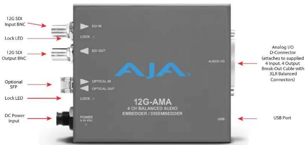
NOTE: The LOCK LED indicates valid input video by color. Off is no signal, green is SD video, red is HD video, amber is 3G video, purple is 6G video, and blue is 12G video.
DIP Switches
The 12G-AMA has an 8 position DIP switch accessible through a cut-out in the bottom of the unit. The DIP switches are used to configure the unit's audio embedding and disembedding, and control ancillary data.
Figure 1. 12G-AMA DIP Switches and Label

Factory default switch settings are all in the leftmost position.
The exact functions of the DIP switches are described in "DIP Switch Settings" on page 10
Mini-Config Control
The Mini-Config application can also be used to configure the unit's audio embedding and disembedding functions. Configuration set via Mini-Config is stored in the unit through subsequent power cycles.
Installing and using Mini-Config are described in "USB Control and Setup—Using AJA Mini-Config" on page 12
NOTE: DIP switch 1 must be ON (Remote, Right) to permit Mini-Config control of the unit.
Installation
NOTE: AJA does not support third-party SFP modules. Use of a non-AJA SFP module will void the warranty.
12G-AMA-T ships with a 12G-SDI Fiber LC single channel SFP transmitter.
12G-AMA-R ships with a 12G-SDI Fiber LC single channel SFP receiver.
12G-AMA-TR ships with a 12G-SDI Fiber LC channel SFP transceiver.
12G-AMA-T-ST ships with a 12G-SDI Fiber ST single channel SFP transmitter.
12G-AMA-R-ST ships with a 12G-SDI Fiber ST single channel SFP receiver.
Typically, 12G-AMA installation consists of the following steps:
- Ensure the converter is disconnected from power.
- Connect video equipment to the converter BNCs.
- If applicable, connect fiber to the 12G-SDI Fiber LC or ST single channel SFP receiver, transmitter or transceiver.

CLASS 1 LASER PRODUCT
Warning! Active fiber-optic cables emit radiation invisible to the human eye. Do not look directly at the end of an active fiber-optic cable or the fiber connector on a 12G-AMA-R, 12G-AMA-R-ST, 12G-AMA-T, 12G-AMA-T-ST, or 12G-AMA-TR; these models are Class 1 Laser Products.
Figure 2. 12G-AMA to Fiber LC Single Channel SFP Example

natural_image
Close-up of a gray electronic device with three connectors and a cable inserted into a socket (no visible text or symbols)NOTE: Fiber optic interconnections can be severely compromised by dirt, oils, or other contaminants. All dust caps should be replaced on cables and equipment whenever 12G-AMA converters are disconnected from fiber optic cables.
- Connect the breakout audio cable to the converter.
- Connect audio equipment to the breakout cable.
- Apply power to the converter (AJA power supply included).
-
The converter will now run using the default factory settings. If you wish to alter the factory settings you can either:
-
Change the DIP switch 2 - 8 settings.
- or -
• Install the AJA Mini-Config software on your computer, - attach the converter via USB,
- change the DIP switch 1 setting to LOCAL, and
- make your changes using the Mini-Config setup screens.
NOTE: For highest reliability, the mini converter relies on convection cooling instead of using a built-in fan. Therefore, when installing the unit, mount in a location where it has access to air for proper cooling. Do not stack the 12G-AMA with other mini converters.
Figure 3. AES Breakout Cable Illustration, XLR Connectors

Table 1. XLR DB25 Breakout Cable Pinouts
| Pin | Function | Pin, | Pin | Function | Pin, |
| 1 | In 4 + | 2, XLR Input D | 14 | In 4 - | 3, XLR Input D |
| 2 | In 4 GND | 1, XLR Input D | 15 | In 3 + | 2, XLR Input C |
| 3 | In 3 - | 3, XLR Input C | 16 | In 3 GND | 1, XLR Input C |
| 4 | In 2+ | 2, XLR Input B | 17 | In 2 - | 3, XLR Input B |
| 5 | In 2 GND | 1, XLR Input B | 18 | In 1 + | 2, XLR Input A |
| 6 | In 1 - | 3, XLR Input A | 19 | In 1 GND | 1, XLR Input A |
| 7 | Out 4 + | 2, XLR Output D | 20 | Out 4 - | 3, XLR Output D |
| 8 | Out 4 GND | 1, XLR Output D | 21 | Out 3 + | 2, XLR Output C |
| 9 | Out 3 - | 3, XLR Output C | 22 | Out 3 GND | 1, XLR Output C |
| 10 | Out 2 + | 2, XLR Output B | 23 | Out 2 - | 3, XLR Output B |
| 11 | Out 2 GND | 1, XLR Output B | 24 | Out 1 + | 2, XLR Output A |
| 12 | Out 1 - | 3, XLR Output A | 25 | Out 1 GND | 1, XLR Output A |
| 13 | NC | NC |
Default Operational Settings
The 12G-AMA converter ships from the factory with the following configuration:
- Local (DIP switch) control.
- Input analog audio channels 1-4 are embedded to SDI output channels 1-4, overwriting any existing embedded audio.
- Input SDI embedded audio channels 1-4 are disembedded to analog audio output channels 1-4.
- All HANC packets pass from SDI input to output, except for embedded output audio channels 1-4.
- Analog audio operating level is set to 0 dBfs = +24 dBu (Pro 1).
If these settings apply to your requirements, you can simply connect the video and audio input and output signal cables and power up the unit.
For other applications, you can configure the unit using its DIP switch settings, or by using the Mini-Config application and a PC or Mac via USB. Analog audio levels as well as video input source and stream selection can only be set using Mini-Config.
DIP Switches
The 12G-AMA DIP switches configure the audio embedding and disembedding functions, and control ancillary data.
DIP Switch Settings
DIP switch settings used to configure various functions are described below.
Table 2. 12G-AMA DIP Switch Setting Descriptions
| SWITCH FUNCTION DIP Set LEFT (default) DIP Set RIGHT | |||
| 1 Control Selects Local (DIP), and | blocks Mini-Config control. | Selects Remote (Mini-Config),and disables DIP switches 2-8. | |
| 2 Audio Embedding forChannels 1/2 (EMBD 1/2) | (ON) Overwrite or embednew channel 1/2 packets. | (OFF) If SW 8 is set to ON: Passany channel 1/2 packets frominput SDI.If SW 8 is set to OFF: Delete allpackets from input SDI. | |
| 3 Audio Embedding forChannels 3/4 (EMDB 3/4) | (ON) Overwrite or embednew channel 3/4 packets. | (OFF) If SW 8 is set to ON: Passany channel 3/4 packets frominput SDI.If SW 8 is set to OFF: Delete allpackets from input SDI. | |
| 4 Channel | Mapping ForLow Embedded Groups(EMBD GRP L) | Switches 4 and 5 operate together to determine Embeddedchannel mapping.0 represents a Left DIP switch position | |
| 5 Channel | Mapping ForHigh Embedded Groups(EMBD GRP H) | 1 represents a Right DIP switch positionRefer to "Embedded Output Channel Mapping" on page 11 forspecific settings. | |
| 6 Channel | Mapping For Low Disembedding Groups (DISEMBD GRP L) | Switches 6 and 7 operate together to determine Disembedded channel mapping.0 represents a Left DIP switch position1 represents a Right DIP switch positionRefer to "Disembedded Input Channel Mapping" on page 12 for specific settings. | |
| 7 Channel | Mapping For High Disembedding Groups (DISEMBD GRP H) | ||
| 8 Pass or | Drop HANC input packets. (PASS HANC) | (ON) All incoming HANC packets are passed unless the embedder settings above require all or part of them to be over-written. | (OFF) All incoming HANC packets are dropped before embedding any new audio packets. Embedder settings above determine all embedded audio output. Disembedding is not affected. |
NOTE: 2048x1080p/psf 29.97 and 30 formats support a maximum of 8 channels of embedded audio. When one of these formats is present and embedding is turned on, the PASS HANC DIP switch will be ignored and all incoming packets will be dropped before embedding any new audio packets.
Switches 4 and 5 Channel Mapping For Embedded Groups
The following table shows how combinations of setting these two switches affects embedded channel mapping.
Table 3. Embedded Output Channel Mapping
| DIP SW 4EMBD GRP L | DIP SW 5EMBD GRP H | Audio Input Channel | SDI Embedded Group | SDI Embedded Output Channel |
| Left (0) Left (0) | 1 —>1 1 | |||
| 2 —>2 | ||||
| 3 —>3 | ||||
| 4 —>4 | ||||
| Right (1) Left (0) | 1 —>2 5 | |||
| 2 —>6 | ||||
| 3 —>7 | ||||
| 4 —>8 | ||||
| Left (0) Right (1) | 1 —>3 9 | |||
| 2 —>10 | ||||
| 3 —>11 | ||||
| 4 —>12 | ||||
| Right (1) Right | (1) 1 —>4 13 | |||
| 2 —>14 | ||||
| 3 —>15 | ||||
| 4 —>16 |
Switches 6 and 7 Channel Mapping For Disembedded Groups
The following table shows how combinations of setting these two switches affects disembedding channel mapping.
Table 4. Disembedded Input Channel Mapping
| DIP SW 6 DISEMBD GRP L | DIP SW 7 DISEMBD GRP H | SDI Embedded Input Group | SDI Embedded Input Channel | Audio Output Channel |
| Left (0) Left (0) 1 1 | →1 | |||
| 2 →2 | ||||
| 3 →3 | ||||
| 4 →4 | ||||
| Right (1) Left (0) 2 | 5 →1 | |||
| 6 →2 | ||||
| 7 →3 | ||||
| 8 →4 | ||||
| Left (0) Right (1) 3 | 9 →1 | |||
| 10 →2 | ||||
| 11 →3 | ||||
| 12 →4 | ||||
| Right (1) Right (1) | 4 13 →1 | |||
| 14 →2 | ||||
| 15 →3 | ||||
| 16 →4 |
USB Control and Setup—Using AJA Mini-Config
Your AJA Mini-Converter can be used right out of the box for some applications since it is designed to recognize inputs and perform standard actions automatically by default. However, to use its full capability, you must use AJA's Mini-Config software application for PCs and Macs. This same application can be used to update to new Mini-Converter software released by AJA.
NOTE: DIP switch 1 must be ON (Remote, Right) to permit Mini-Config control of the unit. If DIP switch 1 is set to OFF (Local, Left), Mini-Config will report status, but its control functions will be locked out.
Acquiring Mini-Config
AJA's Mini-Config application is available for download from the AJA website.
To download the latest Mini-Config package, which includes the Mini-Config application, Mini-Converter firmware, and documentation, go to:
https://www.aja.com/products/mini-config-software
Select either the Windows or Mac icon to download the desired version.
Mini-Converter Documentation
Included with the Mini-Config package is a complete set of documentation for all Mini-Converters supported by Mini-Config. A .PDF of the Installation and Operation Guide for the currently connected Mini-Converter can be accessed from the Mini-Config UI via the Help/Manual drop-down menu.
Documentation for all AJA Mini-Converters that use Mini-Config can also be accessed directly in the Mini-Config download package Documentation folder, and via the Documentation icon available on the Mac installer.
Documentation (and firmware) included with the Mini-Config application are the versions available at the time of distribution. However, Mini-Converter software, firmware and documentation are updated regularly, so newer versions may exist.
To download the latest documentation for an individual Mini-Converter, go to:
https://www.aja.com/family/mini-converters
and navigate to the Support web page of that Mini-Converter.
Installing Mini-Config
PC Installation
To install Mini-Config on a Windows PC:
- Download the application from the AJA website (select the Windows icon on the Mini-Config Support web page).
- Open the AJA_MiniConfig.zip file
- Double-click on the Minilnstaller.msi file.
- A Setup Wizard will guide you through the installation.
Figure 4. Mini-Config PC Setup Wizard

- Click Next to begin. Answer the questions in the subsequent dialogs. When finished, an AJA Mini-Config shortcut will be installed on the desktop, and you will be able to locate the Mini-Config application in the AJA folder in the Programs listing.
NOTE: If the Mini-Config application already exists on the PC, a different Setup Wizard appears.
Figure 5. Mini-Config Setup Wizard, Reinstallation

With this screen you can Repair (reinstall) or Remove (uninstall) Mini-Config on the PC.
Mac Installation
To install the application on a Mac:
NOTE: Mac computers must be Intel-based (G5, G4 and earlier models will not work with Mini-Config).
- Download the application from the AJA website (select the Apple icon on the Mini-Config Support web page).
- Open the AJA_MiniConfig folder.
- Double-click on the AJAMiniConfig.dmg file.
- Answer the prompt and a utility program will be launched.
Figure 6. Mini-Config Mac Installer

- To complete the installation drag the MiniConfig.app icon to the Applications folder.
Running Mini-Config
Connect the Mini-Converter to the PC or Mac via the supplied USB cable. Connect the external power supply (supplied) to the Mini-Converter.
PC Startup
To run Mini-Config on a PC, double-click on the AJA Mini-Config icon on your desktop, or open the AJA folder in the program list and click on the AJA Mini-Config application located inside the Mini-Config folder.

Mac Startup
To run Mini-Config on a Mac, open the Applications folder and locate the AJA Mini-Config application. Double-click the application to launch it.
Saving Setups
A File drop down menu on the Mini-Config application bar allows you to save the current state of the Mini-Converter to a preset file for later recall.

Using this feature you can set up the converter for different applications, storing each configuration (Save Preset As...) with a unique name for easy recall (Open Preset...).
A Revert to Factory Settings menu item similarly allows you to change the settings back to AJA's factory defaults.
Operating Mini-Config
The Mini-Config application provides a graphic interface for viewing settings and updating software. It consists of an information area at the top that shows the available Mini-Converters attached to the computer via USB, with a graphical rendering of the selected Mini-Converter showing all the connectors and their current state.
Colored text next to the connectors indicates the signal type and what the MiniConverter is doing:
- Blue text indicates the values automatically selected
- Black text indicates values that you have manually selected
- Red text indicates the Mini-Converter is not detecting a signal, or cannot operate with the current user settings.
NOTE: Even if no output device is detected, the SDI connector text still shows the signal it is outputting.
NOTE: Configuration settings in red will change based on the attached output device as well as input signals. For improved accuracy and reliability, you should configure the Mini-Converter only when the target output device is attached and input signals are supplied at the inputs.
Screens are virtually the same on both PC and Mac, with subtle differences that reflect the general look of the platform environment.
Figure 7. Example Mini-Config Screen

Selecting a Mini-Converter with the pulldown menu causes this application to connect to the selected converter. The graphic of Mini-Converter and text below it provides:
- Type of converter
- Firmware version
- Serial number of the unit
A status field at the bottom of the screen shows if your application is connected and communicating with the Mini-Converter.
When configuring the Mini-Converter, select it from the top pulldown, view the current settings and change any values. Making a change communicates that new value to the Mini-Converter's non-volatile memory.
Tabbed Screens
The Tabs delineate control screens with groups of controls for each type of task to be performed.
The controls for the actual configuration parameters are specific to each MiniConverter type. When you click on any of the tab buttons, the pane below the tabs will change to match your tab selection. Any changes you make are immediately applied and will be saved, overwriting previous settings.
Input Tab Screen

Click on the Input tab to view and make changes to the Input settings.
Input Select
Select the active video source:
· BNC
• SFP
3G-SDI Level B
For 3G Level B signals, selects either the 16 audio channels of input Stream A or the 16 channels of input Stream B for disembedding. This setting also controls whether output Stream A or output Stream B will receive embedded audio. This control is active whenever a 3G-SDI Level B-DL or B-DS input signal is detected.
Audio-1 Tab Screen

Click on the Audio-1 tab to view and make changes to the audio embedding and disembedding settings.
Analog Audio Inputs
Embed to:
Select the audio group to which you want to embed the incoming analog audio:
- Group 1 (Ch 1-4)
- Group 2 (Ch 5-8)
• Group 3 (Ch 9-12)
• Group 4 (Ch 13-16)
Ch 1/2 Embed:
- Selecting On embeds the analog audio Ch 1/2 pair in the first two channels of the group selected above.
Ch 3/4 Embed:
- Selecting On embeds the analog audio Ch 3/4 pair in the last two channels of the group selected above.
Disembed from:
Choose which SDI embedded audio group will disembed its audio and send it to the four analog audio outputs:
- Group 1 (Ch 1-4)
- Group 2 (Ch 5-8)
- Group 3 (Ch 9-12)
- Group 4 (Ch 13-16)
Audio-2 Tab Screen

Click on the Audio-2 tab to view and make changes to the packet processing and audio level settings.
Packet Processing Control
HANC Data:
- Pass – All incoming HANC packets are passed unless the embedder settings require all or part of them to be over-written.
- Remove – All incoming HANC packets are dropped before embedding any new audio packets. The embedder settings determine all embedded audio output. Disembedding is not affected.
NOTE: 2048x1080p/psf 29.97 and 30 formats support a maximum of 8 channels of embedded audio. When one of these formats is present and embedding is turned on, the PASS HANC setting will be ignored and all incoming packets will be dropped before embedding any new audio packets.
Analog Audio Levels
- Select from Full Scale Digital settings of +24, +18, +15 (professional), or +12dBu (consumer).
About Audio Levels
Professional audio equipment has much higher levels than consumer equipment: a 0 VU reading corresponds to +4 dBu. Connecting a professional +4 dBu device to a consumer audio input (-7 to -8 dBu) may produce overloading, whereas the output of a consumer device probably does not have sufficient power to drive a professional audio input. With consumer and semi-professional audio equipment, a VU reading of 0 dB is typically referenced to -10 dBV, which is equivalent to -7.78 dBu.
Update Tab Screen

Use this Update tab screen to view the software version currently installed on the converter or install new software.
NOTE: When discussing Mini-Converters, "Firmware" is software that will be stored in the Mini-Converter's non-volatile memory and used when it is powered up. This is something different than the Mini-Config application software. The version numbers shown in the Update screen refer only to the firmware.
Installed
This field shows the version of the firmware currently installed inside the MiniConverter.
Desired
This field shows the version of firmware embedded in the Mini-Config application which you can install into the Mini-Converter by clicking the Update button.
Update
This button initiates a software update operation loading the "Desired" version of firmware into the Mini-Converter's non-volatile memory.
Progress
This indicator bar shows the progress of firmware installation.
See "Acquiring Mini-Config" on page 12 and "Installing Mini-Config" on page 13 for more information.
Info Tab Screen

This screen provides basic information about the Mini-Converter. This information is mostly useful when calling AJA Support for service or technical support.
Name
This field allows you to give your Mini-Converter a name. This can be useful if you have several Mini-Converters attached to a Mac/PC via USB so you can distinguish between them easily (especially if they're the same model).
Type
This is the factory set model name of the Mini-Converter.
Assembly
This is the factory assembly number.
Serial Number
This is the factory set unique serial number of your Mini-Converter. If you ever call AJA Support for service, you may be asked for this number.
12G-AMA Family Tech Specs
Video Formats
• (4K) 4096x2160p 23.98, 24, 25, 29.97, 30, 50, 59.94, 60
• (UltraHD) 3840x2160p 23.98, 24, 25, 29.97, 30, 50, 59.94, 60
• (2K) 2048x1080p 50, 59.94, 60
• (HD) 1920x1080p 23.98, 24, 25, 29.97, 30, 50, 59.94, 60
• (HD) 1920x1080i 50, 59.94, 60
• (HD) 1280x720p 50, 59.94, 60*
• (SD) 625i 50
• (SD) 525i 59.94
• RGB and YCbCr, 4:4:4/4:2:2, 10-bit
*1280x720p is Level A Only
NOTE: Raster and frame rate dependent, please see 12G-AMA Video Formats in Documents and Manual.
Video Input Digital
• 1x 12G-SDI BNC, SMPTE 259/292/424/2081/2082
• Single Link SD/HD/2K/UltraHD/4K
• Single Link 3G-SDI Level A, B-DL, or B-DS, SMPTE 425
Video Input Digital - Additional for 12G-AMA-R and 12G-AMA-TR Only
• 1x 12G-SDI Fiber LC connector, SMPTE 297/259/292/424/2081/2082
• Wavelength: Rx 1260 nm (min), 1620 nm (max)
• Optical Sensitivity: -10 dBm (min 12 Gbps), -14 dBm (min 3 Gbps)
• Overload Power: -2 dBm (min)
Video Input Digital - Additional for 12G-AMA-R-ST Only
• 1x 12G-SDI Fiber ST connector, SMPTE 297/259/292/424/2081/2082
• Wavelength: Rx 1260 nm (min), 1620 nm (max)
• Optical Sensitivity: -10 dBm (min 12 Gbps), -14 dBm (min 3 Gbps)
• Overload Power: -2 dBm (min)
Video Output Digital
• 1x 12G-SDI BNC, SMPTE 259/292/424/2081/2082
• Single Link SD/HD/2K/UltraHD/4K
• Single Link 3G-SDI Level A, B-DL, or B-DS, SMPTE 425
Video Output Digital - Additional for 12G-AMA-T, and 12G-AMA-TR Only
• 1x 12G-SDI Fiber LC connector, SMPTE 297/259/292/424/2081/2082
- Nominal Wavelength: Tx 1260 nm (min), 1310 nm (typ), 1360 nm (max)
• Optical Power: -5 dBm (min), 0.5 dBm (max)
• Extinction Ratio: 5.4 dB (min)
Video Output Digital - Additional for 12G-AMA-T-ST Only
• 1x 12G-SDI Fiber ST connector, SMPTE 297/259/292/424/2081/2082
- Nominal Wavelength: Tx 1260 nm (min), 1310 nm (typ), 1360 nm (max)
• Optical Power: -5 dBm (min), 2 dBm (max)
• Extinction Ratio: 3.4 dB (min)
Cable Equalization
(Belden 1694A coax)
• 12 Gbps, 65m
- 6 Gbps, 125m
• 3 Gbps, 190m
• 1.5 Gbps, 200m
• 270 Mbps, 405m
Audio Inputs and Outputs
- Balanced Analog Audio, 1x 25 pin D female connector on the converter, 4-channels in, 4-channels out
- Breakout cable provided with 1x 25 pin D male connector:
- 4x XLR female input breakout connectors
- 4x XLR male output breakout connectors
Digital Audio Converters
• 24-bit
Embedded Audio
- SMPTE 272M (SD): 20-bit, 48 kHz synchronous
- SMPTE 299M (12G/6G/3G/1.5G): 24-bit, 48 kHz synchronous
- Incoming embedded audio can be passed, removed, or overridden
- Up to 16 channels supported
NOTE: 2048x1080p/PsF 29.97 and 30 formats support a maximum of 8-channels embedded audio.
Audio Latency
- Embed Path 1100 μsec
• Disembed Path 1200 μsec
Analog Audio Levels
Configured via Mini-Config software:
• Pro 1: 0 dBfs = +24 dBu
• Pro 2: 0 dBfs = +18 dBu
• Pro 3: 0 dBfs = +15 dBu
- Consumer 1: 0 dBfs = +12 dBu
User Interface
- External DIP switch
- USB port used with Mini-Config software application to configure the device via PC/Mac
Size (w x d x h)
- 5.8" x 3.1" x 1.0" (147.32 x 78.74 x 25.4 mm)
Weight
• 0.6 lb (0.3 kg)
Power
• +5-16VDC, 10 watts. power supply required, included with purchase
Environment
- Safe Operating Temperature: 0 to 40 C (32 to 104 F)
- Safe Storage Temperature (Power OFF): -40 to 60 C (-40 to 140 F)
- Operating Relative Humidity: 10-90% noncondensing
- Operating Altitude: <3,000 meters (<10,000 feet)
12G-AMA Video I/O Formats
4K/UltraHD Inputs Supported
1x 12Gb SDI:
Format Frame Rate Colorspace Sampling Bit Depth
• 3840x2160p 23.98, 24, 25, 29.97, 30 YCbCr/RGB 4:4:4 10
• 3840x2160p 50, 59.94, 60 YCbCr 4:2:2 10
• 4096x2160p 23.98, 24, 25, 29.97, 30 YCbCr/RGB 4:4:4 10
• 4096x2160p 50, 59.94, 60 YCbCr 4:2:2 10
1x 6Gb SDI:
Format Frame Rate Colorspace Sampling Bit Depth
• 3840x2160p 23.98, 24, 25, 29.97, 30 YCbCr 4:2:2 10
• 4096x2160p 23.98, 24, 25, 29.97, 30 YCbCr 4:2:2 10
2K/HD Inputs Supported
1x 3Gb SDI:
| Format Frame Rate | Level A/B | Colorspace Sampling Bit Depth | |||
| • 1280x720p | 50, 59.94, 60 | A | YCbCr/RGB | 4:4:4 | 10 |
| • 1920x1080i | 50, 59.94, 60 | A or B-DL | YCbCr/RGB | 4:4:4 | 10 |
| • 1920x1080p | 23.98, 24, 25, 29.97, 30 | A or B-DL | YCbCr/RGB | 4:4:4 | 10 |
| • 1920x1080p | 50, 59.94, 60 | A or B-DL | YCbCr | 4:2:2 | 10 |
| • 1920x1080PsF | 23.98, 24, 25, 29.97, 30 | A or B-DL | YCbCr/RGB | 4:4:4 | 10 |
| • 2048x1080p | 23.98, 24, 25, 29.97, 30 | A or B-DL | YCbCr/RGB | 4:4:4 | 10 |
| • 2048x1080p | 50, 59.94, 60 | A or B-DL | YCbCr | 4:2:2 | 10 |
| • 2048x1080PsF | 23.98, 24, 25, 29.97, 30 | A or B-DL | YCbCr/RGB | 4:4:4 | 10 |
1x 1.5Gb SDI:
Format Frame Rate Colorspace Sampling Bit Depth
• 1280x720p 50, 59.94, 60 YCbCr 4:2:2 10
• 1920x1080i 50, 59.94, 60 YCbCr 4:2:2 10
• 1920x1080p 23.98, 24, 25, 29.97, 30 YCbCr 4:2:2 10
• 1920x1080PsF 23.98, 24, 25, 29.97, 30 YCbCr 4:2:2 10
• 2048x1080p 23.98, 24, 25, 29.97, 30 YCbCr 4:2:2 10
• 2048x1080PsF 23.98, 24, 25, 29.97, 30 YCbCr 4:2:2 10
SD Inputs Supported
1x 270Mb SDI:
Format Frame Rate Colorspace Sampling Bit Depth
• 525i 59.94 YCbCr 4:2:2 10
• 625i 50
YCbCr 4:2:2 10
Appendix B – Safety and Compliance
Federal Communications Commission (FCC) Compliance Notices
Class A Interference Statement
This equipment has been tested and found to comply with the limits for a Class A digital device, pursuant to Part 15, Subpart B of the FCC Rules. These limits are designed to provide reasonable protection against harmful interference in a residential installation. This equipment generates, uses, and can radiate radio frequency energy and, if not installed and used in accordance with the instructions, may cause harmful interference to radio communications. However, there is no guarantee that interference will not occur in a particular installation. If this equipment does cause harmful interference to radio or television reception, which can be determined by turning the equipment off and on, the user is encouraged to try to correct the interference by one or more of the following measures:
- Reorient or relocate the receiving antenna.
- Increase the separation between the equipment and receiver.
- Connect the equipment into an outlet on a circuit different from that to which the receiver is connected.
- Consult the dealer or an experienced radio/TV technician for help.
FCC Caution
This device complies with Part 15 of the FCC Rules. Operation is subject to the following two conditions: (1) This device may not cause harmful interference, and (2) this device must accept any interference received, including interference that may cause undesired operation.
Canadian ICES Statement
Canadian Department of Communications Radio Interference Regulations
This digital apparatus does not exceed the Class A limits for radio-noise emissions from a digital apparatus as set out in the Radio Interference Regulations of the Canadian Department of Communications. This Class A digital apparatus complies with Canadian ICES-003.
European Union and European Free Trade Association (EFTA) Regulatory Compliance
This equipment may be operated in the countries that comprise the member countries of the European Union and the European Free Trade Association. These countries, listed in the following paragraph, are referred to as The European Community throughout this document:
AUSTRIA, BELGIUM, BULGARIA, CYPRUS, CZECH REPUBLIC, DENMARK, ESTONIA, FINLAND, FRANCE, GERMANY, GREECE, HUNGARY, IRELAND, ITALY, LATVIA, LITHUANIA, LUXEMBOURG, MALTA, NETHERLANDS, POLAND, PORTUGAL, ROMANIA, SLOVAKIA, SLOVENIA, SPAIN, SWEDEN, UNITED KINGDOM, ICELAND, LICHTENSTEIN, NORWAY, SWITZERLAND
Marking by this symbol indicates compliance with the Essential Requirements of the EMC Directive of the European Union 2014/30/EU.

This equipment meets the following conformance standards:
Safety
EN 60065: 2014 (T-Mark License)
IEC 60065: 2014 (CB Scheme Report/Certificate)
EN 62368-1: 2014 + A11 (T-Mark License)
IEC 62368-1: 2014 (CB Scheme Certificate)
Additional licenses issued for specific countries available on request.
Emissions
EN 55032: 2012 + AC: 2013, CISPR 32: 2015,
EN 61000-3-2: 2014, EN 61000-3-3: 2013
Immunity
EN 55103-2: 2009
EN 61000-4-2:2009, EN 61000-4-3:2006 +A1:2008 +A2:2010,
EN 61000-4-4:2004 + A1:2010, EN 61000-4-5:2006, EN 61000-4-6:2009
EN 61000-4-11:2004
Environments: E2, E3 and E4
Laser
EN 60825-1: 2007 and EN 60825-2: 2004 +A2: 2010,
CDRH Compliant Class 1 (TUV Cert No. 50135086)
Also Licensed for Standards: FDA 21 CFR 1040.10 and 1040.11
The product is also licensed for additional country specific standards as required for the International Marketplace.

Warning! This is a Class A product. In a domestic environment, this product may cause radio interference, in which case, the user may be required to take appropriate measures.
This symbol on the product or its packaging indicates that this product must not be disposed of with your other household waste. Instead, it is your responsibility to dispose of your waste equipment by handing it over to a designated collection point for the recycling of waste electrical and electronic equipment. The separate collection and recycling of your waste equipment at the time of disposal will help conserve natural resources and ensure that it is recycled in a manner that protects human health and the environment. For more information about where you can drop off your waste for recycling, please contact your local authority, or where you purchased your product.
Korea KCC Compliance Statement
사용자안내문
Taiwan Compliance Statement
警告使用者:
This is a Class A product based on the standard of the Bureau of Standards, Metrology and Inspection (BSMI) CNS 13438, Class A. In a domestic environment this product may cause radio interference in which case the user may be required to take adequate measures.
Japan Compliance Statement
This is a Class A product based on the standard of the VCCI Council (VCCI-32: 2016). If this equipment is used in a domestic environment, radio interference may occur, in which case, the user may be required to take corrective actions.
Translated Warning and Caution Messages
The following caution statements, warning conventions, and warning messages apply to this product and manual.

Warning Symbol

Caution Symbol
Before Operation Please Read These Instructions

Warning! Read and follow all warning notices and instructions marked on the product or included in the documentation.
Warning! Do not use this device near water and clean only with a dry cloth.
Warning! Do not block any ventilation openings. Install in accordance with the manufacturer's instructions.
Warning! Do not install near any heat sources such as radiators, heat registers, stoves, or other apparatus (including amplifiers) that produce heat.
Warning! Do not defeat the safety purpose of the polarized or grounding-type plug. A polarized plug has two blades with one wider than the other. A grounding type plug has two blades and a third grounding prong. The wide blade or the third prong are provided for your safety. If the provided plug does not fit into your outlet, consult an electrician for replacement of the obsolete outlet.
Warning! Since the Mains plug is used as the disconnection for the device, it must remain readily accessible and operable.
Warning! Protect the power cord from being walked on or pinched particularly at plugs, convenience receptacles, and the point where they exit from the device.
Warning! Unplug this device during lightning storms or when unused for long periods of time.
Warning! Refer all servicing to qualified service personnel. Servicing is required when the device has been damaged in any way, such as power-supply cord or plug is damaged, liquid has been spilled or objects have fallen into the device, the device has been exposed to rain or moisture, does not operate normally, or has been dropped.
Warning! Do not open the chassis. There are no user-serviceable parts inside. Opening the chassis will void the warranty unless performed by an AJA service center or licensed facility.
Warning! Disconnect the external AC power supply line cord(s) from the mains power before moving the unit.
Warning! Only use attachments and accessories specified and/or sold by the manufacturer.
Caution! 12G-AMA devices require the use of "single mode 1310nm compatible" fiber optic cable.
CLASS 1 LASER PRODUCT

PRODUTO LASER DE CLASSE 1

PRODUITS LASER DE CLASSE 1

PRODOTTO LASER DI CLASSE 1

CLASE 1 LASER PRODUCTO

KLASSE 1 LASER- PRODUKT
Warning! Active fiber-optic cables emit radiation invisible to the human eye. Do not look directly at the end of an active fiber-optic cable; the 12G-AMA is a Class 1 Laser Product.
Warranty and Liability Information
Limited Warranty on Hardware
AJA Video Systems, Inc. (AJA Video) warrants that the hardware product, not including software components, will be free from defects in materials and workmanship for a period of five years from the date of purchase. AJA Video provides a separate software warranty as part of the license agreement applicable to software components.
If the Customer brings a valid claim under this limited warranty for a hardware product (hereafter, a "product") during the applicable warranty period, AJA Video will, at its sole option and as the Customer's sole remedy for breach of the above warranty, provide one of the following remedies:
- Repair or facilitate the repair the product within a reasonable period of time, free of charge for parts and labor.
- Replace the product with a direct replacement or with a product that performs substantially the same function as the original product.
- Issue a refund of the original purchase price less depreciation to be determined based on the age of the product at the time remedy is sought under this limited warranty.
To obtain service under this warranty, the Customer must notify AJA Video of the defect before expiration of the warranty period and make suitable arrangements for the performance of service by contacting AJA Video support through the channels set forth on the support contacts web page at https://www.aja.com/support. Except as stated, the Customer shall bear all shipping, packing, insurance and other costs, excluding parts and labor, to effectuate repair. Customer shall pack and ship the defective product to a service center designated by AJA Video, with shipping charges prepaid. AJA Video shall pay to return the product to Customer, but only if to a location within the country in which the AJA Video service center is located. SOME JURISDICTIONS DO NOT ALLOW THE EXCLUSION OF IMPLIED WARRANTIES OR LIMITATIONS ON APPLICABLE STATUTORY RIGHTS OF A CONSUMER, SO SOME OR ALL OF THE TERMS OF THIS PARAGRAPH MAY NOT APPLY TO YOU.
Limitation of Liability
Under no circumstances shall AJA video BE LIABLE IN ANY WAY FOR ANY LOST, CORRUPTED OR DESTROYED DATA, FOOTAGE OR WORK, OR FOR ANY OTHER INDIRECT, SPECIAL, INCIDENTAL OR CONSEQUENTIAL DAMAGES OR LOST PROFITS, OR FOR ANY THIRD PARTY CLAIM, IN CONNECTION WITH THE PRODUCT, WHETHER RESULTING FROM DEFECTS IN THE PRODUCT, SOFTWARE OR HARDWARE FAILURE, OR ANY OTHER CAUSE WHATSOEVER, EVEN IF AJA VIDEO HAS BEEN ADVISED OF THE POSSIBILITY OF SUCH DAMAGES. AJA VIDEO'S LIABILITY IN CONNECTION WITH THE PRODUCT SHALL UNDER NO CIRCUMSTANCES EXCEED THE PURCHASE PRICE PAID FOR THE PRODUCT. The foregoing limitations apply even if any remedy set forth in this LIMITED WARRANTY fails of its essential purpose. SOME JURISDICTIONS DO NOT ALLOW THE LIMITATION OF LIABILITY FOR PERSONAL INJURY, OR OF INCIDENTAL OR CONSEQUENTIAL DAMAGES, SO SOME OR ALL OF THE TERMS OF THIS PARAGRAPH MAY NOT APPLY TO YOU.
Governing Law and Language; Your Rights
This limited warranty is the only warranty provided by AJA Video on the hardware product. It supersedes all prior or contemporaneous understandings regarding such subject matter. No amendment to or modification of this warranty will be binding unless in writing and signed by AJA Video. The laws of the State of California, USA will govern this warranty and any dispute arising from it. Any translation of this
Agreement is intended for convenience and to meet local requirements and in the event of a dispute between the English and any non-English versions, the English version of this warranty will govern. This limited warranty gives you specific legal rights and you may have other rights that vary from jurisdiction to jurisdiction, some of which are noted above.
Symbols
3G-AMA I/O Connections 6
3G-AMA Simplified Block Diagram 6
A
AJA Support 2
Audio-1 Tab Screen 18
Audio-2 Tab Screen 19
B
Breakout Cable Pinouts 9
D
Default Operational Settings 10
DIP Switches 7
DIP Switch Settings 10
Documentation
Downloading 13
Mini-Converter 13
|
Info Tab Screen 21
Input Tab Screen 17
Installation 7
M
Mini-Config
Installation on Mac 14
Installation on PC 13
Operation 15
Screen Description 16
Startup on Mac 15
Startup on PC 15
Mini-Config Screen
Info Tab Screen 21
Update Tab Screen 20
Mini-Converter Documentation 13
O
Overview 4
S
Saving Setups 15
T
Technical Support 2
U
Update Tab Screen 20
X
XLR DB25 Breakout Cable 9


- 12G-AMA Mini-Converter
- Installation and Operation Guide
- Trademarks
- Copyright
- Contacting AJA Support
- Contents
- Notices 2
- Chapter 1 – Introduction .....4
- Chapter 2 – Operation....10
- Appendix A – Specifications .....22
- Appendix B – Safety and Compliance ..... 27
- Warranty and Liability Information....36
- Index. 38
- Chapter 1 – Introduction
- Overview
- Fiber Options
- LC Options
- ST Options
- Features
- DIP Switches
- Mini-Config Control
- Installation
- Default Operational Settings
- DIP Switch Settings
- Switches 4 and 5 Channel Mapping For Embedded Groups
- Switches 6 and 7 Channel Mapping For Disembedded Groups
- USB Control and Setup—Using AJA Mini-Config
- Acquiring Mini-Config
- Mini-Converter Documentation
- Installing Mini-Config
- PC Installation
- Mac Installation
- Running Mini-Config
- PC Startup
- Mac Startup
- Saving Setups
- Operating Mini-Config
- Tabbed Screens
- Input Tab Screen
- Input Select
- 3G-SDI Level B
- Audio-1 Tab Screen
- Analog Audio Inputs
- Embed to:
- Ch 1/2 Embed:
- Ch 3/4 Embed:
- Disembed from:
- Audio-2 Tab Screen
- Packet Processing Control
- HANC Data:
- Analog Audio Levels
- About Audio Levels
- Update Tab Screen
- Installed
- Desired
- Update
- Progress
- Info Tab Screen
- Name
- Type
- Assembly
- Serial Number
- 12G-AMA Family Tech Specs
- Video Formats
- Video Input Digital
- Video Input Digital - Additional for 12G-AMA-R and 12G-AMA-TR Only
- Video Input Digital - Additional for 12G-AMA-R-ST Only
- Video Output Digital
- Video Output Digital - Additional for 12G-AMA-T, and 12G-AMA-TR Only
- Video Output Digital - Additional for 12G-AMA-T-ST Only
- Environment
- 12G-AMA Video I/O Formats
- 4K/UltraHD Inputs Supported
- 1x 12Gb SDI:
- 1x 6Gb SDI:
- 2K/HD Inputs Supported
- 1x 3Gb SDI:
- 1x 1.5Gb SDI:
- SD Inputs Supported
- Appendix B – Safety and Compliance
- Federal Communications Commission (FCC) Compliance Notices
- Class A Interference Statement
- FCC Caution
- Canadian ICES Statement
- European Union and European Free Trade Association (EFTA) Regulatory Compliance
- Korea KCC Compliance Statement
- Taiwan Compliance Statement
- 警告使用者:
- Japan Compliance Statement
- Translated Warning and Caution Messages
- Before Operation Please Read These Instructions
- Warranty and Liability Information
- Limited Warranty on Hardware
- Limitation of Liability
- Governing Law and Language; Your Rights
- Symbols
- A
- B
- D
- |
- M
- O
- S
- T
- U
- X
Brand : AJA
Model : 12G-AMA-T
Category : Audio/Video Equipment