A-2240ZE - Printer Argox - Free user manual and instructions
Find the device manual for free A-2240ZE Argox in PDF.

User questions about A-2240ZE Argox
0 question about this device. Answer the ones you know or ask your own.
Ask a new question about this device
Download the instructions for your Printer in PDF format for free! Find your manual A-2240ZE - Argox and take your electronic device back in hand. On this page are published all the documents necessary for the use of your device. A-2240ZE by Argox.
USER MANUAL A-2240ZE Argox
A SERIE PRINTERS A-2240, A-2240E, A-2240Z, A-2240ZE, A-3140, A-3140Z A-2240M, A-2240ME User's Manual
natural_image
Illustration of a printer with paper filter and paper edge (no text or symbols)
Ribbon & Media Installation video
Website: http://www.argox.com
Introduction
Proprietary Statement
This manual contains proprietary information of Argox Information Co., Ltd. It is intended solely for the information and use of parties operating and maintaining the equipment described herein. Such proprietary information may not be used, reproduced, or disclosed to any other parties for any other purpose without the expressed written permission of Argox Information Co., Ltd.
Product Improvements
Continuous improvement of products is a policy of Argox Information Co., Ltd. All specifications and signs are subject to change without notice.
FCC Compliance Statement
This equipment has been tested and found to comply with the limits for a Class A digital device, pursuant to Part 15 of the FCC Rules. These limits are designed to provide reasonable protection against harmful interference in a residential installation. This equipment generates, uses, and can radiate radio frequency energy and, if not installed and used in accordance with the instructions, may cause harmful interference to radio communications. However, there is no guarantee that the interference will not occur in a particular installation. If this equipment does cause harmful interference to radio or television reception, which can be determined by turning the equipment off and on, the user is encouraged to try to correct the interference by the following measures:
- Reorient or relocate the receiving antenna.
- Increase the separation between the equipment and the receiver.
- Connect the equipment into a different outlet on a different circuit.
- Consult the dealer or an experience Radio/TV technician for help.
This unit was tested with shielded cables on the peripheral devices. Shielded cables must be used with the unit to insure compliance. The user is cautioned that any changes or modifications not expressly approved by Argox Information Co., Ltd. could void the user's authority to operate the equipment.
Liability Disclaimer
Argox Information Co., Ltd. takes steps to assure that the company's published engineering specifications and manuals are correct; however, errors do occur. Argox Information Co., Ltd. reserves the right to correct any such errors and disclaims any resulting liability. In no event shall Argox Information Co., Ltd. or
2
A Series User's Manual
anyone else involved in the creation, production, or delivery of the accompanying product (including hardware and software) be liable for any damages whatsoever (including, without limitation, damages for loss of business profits, business interruption, loss of business information, or other pecuniary loss) arising out of the use of or the results of use of or inability to use such product, even if Argox Information Co., Ltd. has been advised of the possibility of such damages.
CAUTION:
Any changes or modifications not expressly approved by the party responsible for compliance could void the user's authority to operate the equipment.
Safety

Supplemental Information: This device complies with the requirement of FCC Part 15 Rules. Operation is subject to the following two Conditions: (1) This device may not cause harmful interference, and (2) this device must accept any interference received, including interference that may cause undesired operation
INDUSTRY CANADA NOTICE:
This device complies with Industry Canada ICES-003 class A requirements. Cet equipement est conforme a ICES-003 classe A de la norm Industrielle Canadian.

Please only use adapters with the following electrical characteristics and are certified by current legislation. Using other adapters may damage the device and void the warranty also cause risks to the user. Features Output: 24VDC, 2.4A

The manufacturer declares under sole responsibility that this product conforms to the following standards or other normative documents: EMC: EN 2010 Class A EN 55024:2010
3
A Series User's Manual

Argox Information Co., Ltd certifies that the following products and/or components are compliant with the current requirements of the European Union Restriction on the use of Hazardous Substances (RoHS) Directive, 2011/65/EC.
4
A Series User's Manual
Table of Contents
Introduction....2
Proprietary Statement 2
Product Improvements.... 2
FCC Compliance Statement 2
Liability Disclaimer....2
Safety 3
Getting Started....7
Unpacking....7
Package Contents....8
Connecting the Power Supply....9
Getting to Know Your Printer.... 12
Parts and Features 12
Controls and Indicators.... 14
Loading Ribbon and Media.... 16
Loading a Ribbon.... 16
Loading Media 21
Standard Mode 21
Peel Off Mode 26
Cutter Mode 31
Configuration and Configuration 39
Performing Calibration and a Configuration Report.... 39
Resetting Printer to Factory Defaults 41
Sensor Detection 42
Detection Area of the Transmissive Sensor (edge)....42
Detection Area of the Transmissive Sensor (centre)....43
Detection Area of the Reflective Sensor 44
Computer Connections.... 45
USB Interface Requirements 45
Serial (RS-232) Interface Requirements 46
Serial Cabling Requirements 46
Ethernet 10/100 Internal Printer Server Option 48
Communicating with the Printer 50
Installing a Plug and Play printer driver (for USB only).... 51
Installing the Printer Driver.... 58
5
A Series User's Manual
Troubleshooting 70
LED Diagnosis 70
Miscellaneous 73
Recovery....74
Caring for Your Printer....75
Cleaning....75
Media Sensor 75
Thermal Print Head 75
Replacing Thermal Print Head 78
Technical Reference 81
General Specifications 81
Fonts, Bar Codes and Graphics Specification 84
Printer Programming Language A, PPLA 84
Printer Programming Language B, PPLB 85
Printer Programming Language Z, PPLZ.... 86
Interface Specifications 87
USB Interface 87
Serial 88
Ethernet 89
Connection with host 90
Appendix I - Installing the Extension Card....92
6
A Series User's Manual
Getting Started
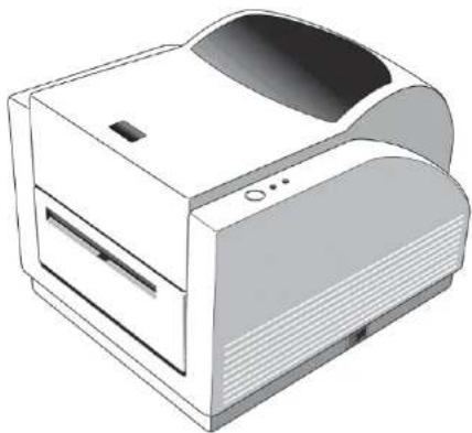
Congratulations on choosing the Argox Amigo Series desktop barcode printer. This user's manual will help you get to know your new printer. The manual includes a guide to operating the printer as well as related information on troubleshooting, maintenance, and technical reference. Illustrations are provided to help you quickly become familiar with the printer.
Unpacking
After receiving your printer, please check for possible shipping damage:
- Inspect the outside of both the box and the printer for possible damage.
- Open the top cover of the printer to see if the media compartments are in order.
Note: If damage has occurred, contact your shipping company immediately to file a claim.
7
A Series User's Manual
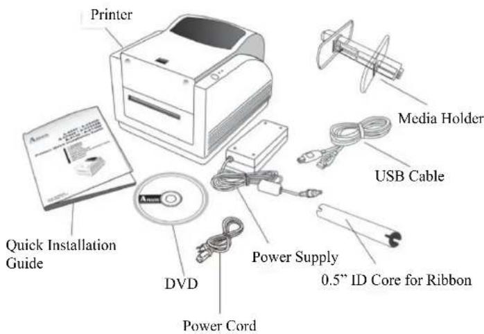
Package Contents
- Printer
- Quick Installation Guide
• DVD
• Power Supply - Power Cord
- USB Cable
• 0.5" ID Core for Ribbon
• Media Holder
8
A Series User's Manual
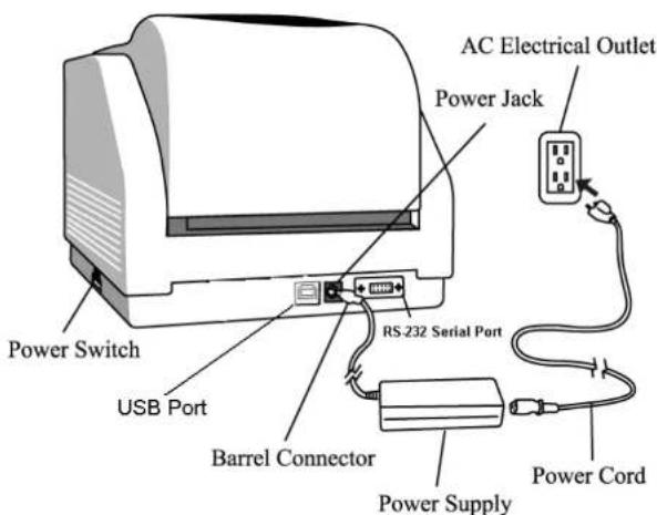
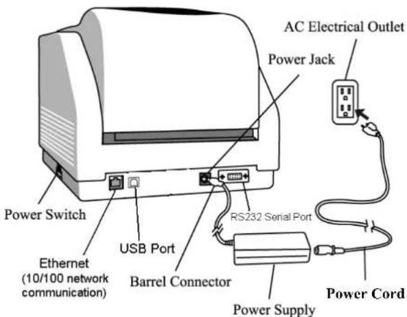
Connecting the Power Supply
Connect the power supply as below.
WARNING: 1. do not operate the printer and power supply in an area where they might get wet.
- Make sure the power switch is in the "O" position.
- Insert the barrel connector of the power supply into the power jack on the back of the printer.
- Insert the separate power cord into the power supply.
- Plug the other end of the cord into an AC electrical outlet.
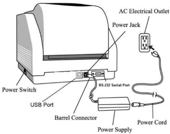
A-2240/A-3140/A-2240M
9
A Series User's Manual
10
A Series User's Manual
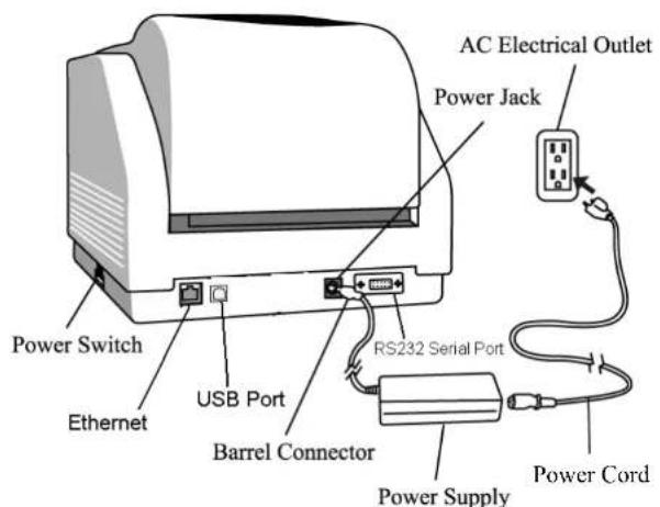
A-2240E/A-2240ME
11
A Series User's Manual
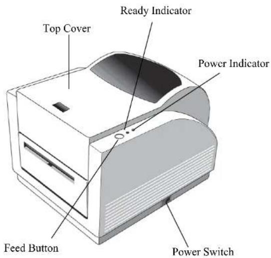
Getting to Know Your Printer
The illustrations that follow describe the printer's parts, features, controls, and indicators.
Parts and Features
12
A Series User's Manual
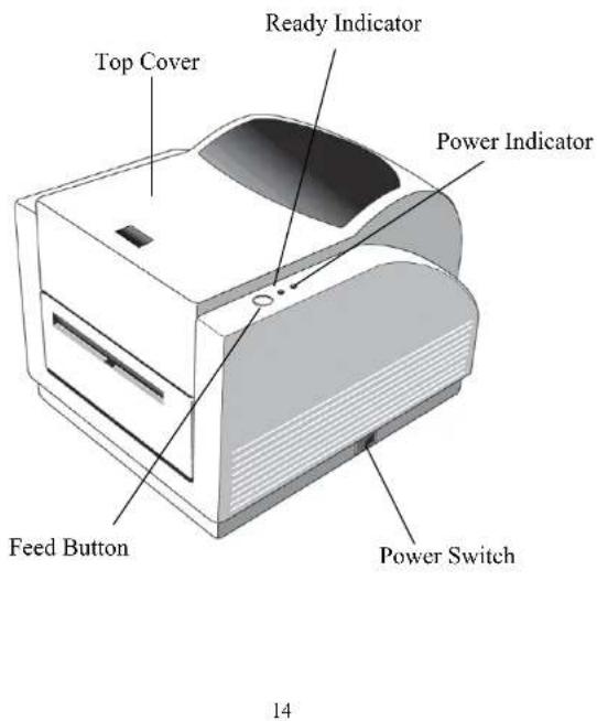
Controls and Indicators
The printer's controls and indicators are shown in the diagram below. The following table explains control and indicator functions.
A Series User's Manual
| Control / Indicator | Function |
| Power Switch | On: turns on normal operationOff: turns off powerNote: Turn power off before connecting or disconnecting cables |
| Power Indicator | Green light shows printer power onLight off shows printer power offBlinking light indicates error has occurred |
| Ready Indicator | Green shows printer is ready to operateBlinking light indicates printer is paused or receiving dataSeagull driver status monitor |
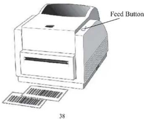
| Feed Button | Press to advance the label media to the first printing positionPress to take the printer out of "pause"Press and hold while turning on the power to print out a configuration profile |
15
A Series User's Manual
Loading Ribbon and Media
This section describes how to load ribbon and media in the Amigo Series printers.
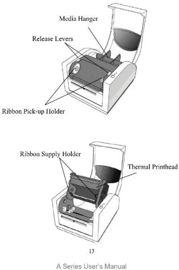
Loading a Ribbon
Note: This section does not apply to direct thermal printing.
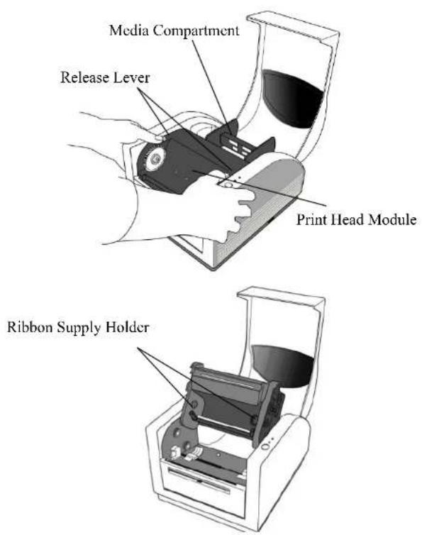
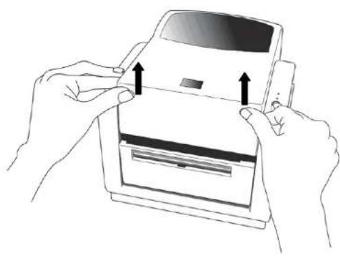
- Lift the top cover to expose the media compartment.
- Unlatch the print head module by pushing the two purple release levers on the sides toward the rear.
- Turn over the print head module to expose the ribbon supply holder.
natural_image
Illustration of hands holding a digital payment card with arrows indicating press or usage (no text or symbols present)16
A Series User's Manual
17
A Series User's Manual
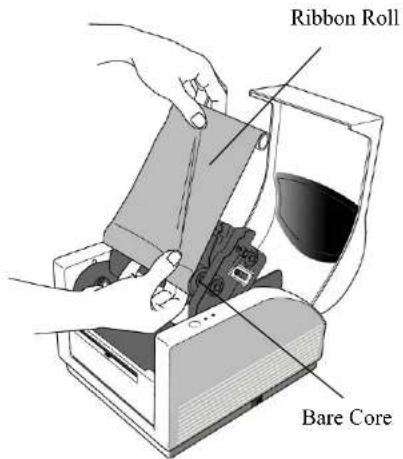
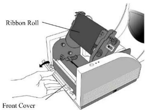
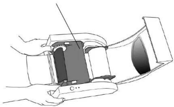
- Unwrap the ribbon roll pack and separate the ribbon roll and the bare core.
- Attach the edge of the ribbon on the bare core and wind it a little bit onto the core.
- Insert the ribbon roll into the supply holder. (First snap in the right side and then the left side.)
18
A Series User's Manual
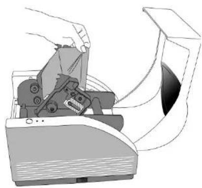
- Turn back the print head module and then insert the bare core into the pick-up holder. (First snap in the right side, then the left side.)
natural_image
Illustration of a hand operating a printer with a paper airplane (no text or symbols visible)19
A Series User's Manual
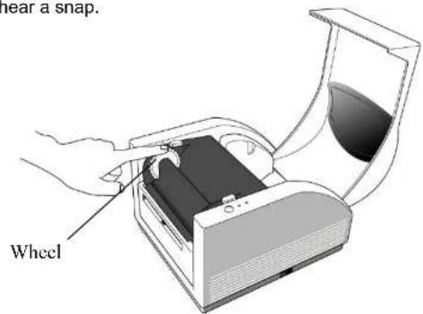
- Turn the wheel of the print head module to ensure the ribbon is tightly wound.
- Press down the print head module on both sides firmly till you hear a snap.
A Series User's Manual
Loading Media
The Amigo Series printers offer three different loading modes: standard, peel-off, or with a cutter.
• Standard mode allows you to collect each label freely.
- Peel-off mode peels backing material away from the label as it prints. After the label is removed, the next label prints.
• Cutter mode automatically cuts the label after it prints.
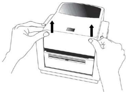
Standard Mode
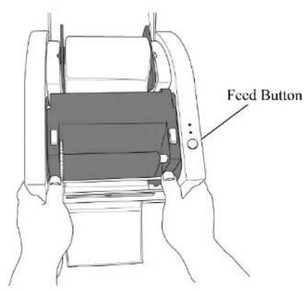
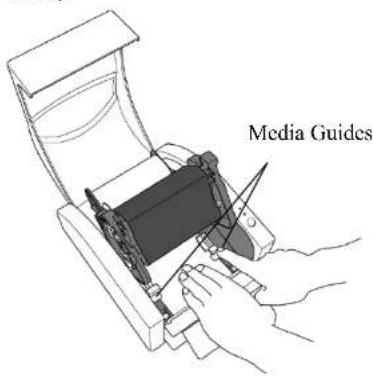
- Lift the top cover to expose the media compartment.
natural_image
Illustration of hands holding a printer with arrows indicating press or binding (no text or symbols present)21
A Series User's Manual
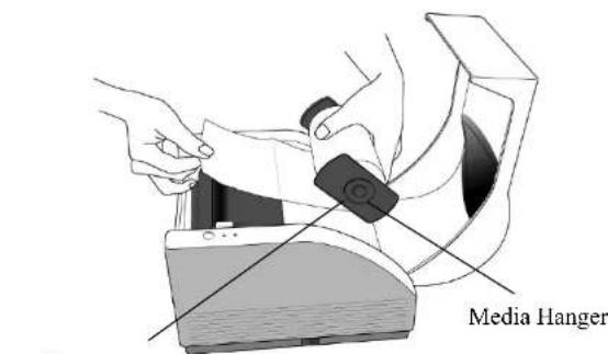
- Remove the media hanger.
- Load the media roll onto the hanger.
- Unlatch the print head module.
- Open the front cover to allow the labels pass through the slot.
Media Compartment
A Series User's Manual
- Lead the labels through the media guides with the other hand. The media guide can be adjusted centrally to fit with different label widths.
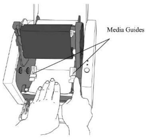
23
A Series User's Manual
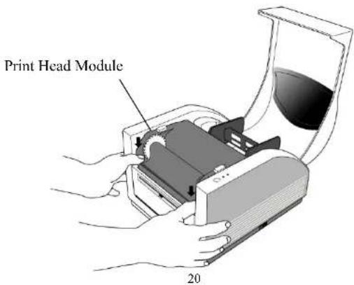
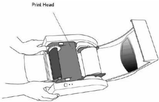
- Press the print head module down firmly on both sides until you hear a snap.
Print Head Module
natural_image
Line drawing of a hand holding a device with a cable inserted, showing internal components and a screen (no text or symbols)24
A Series User's Manual
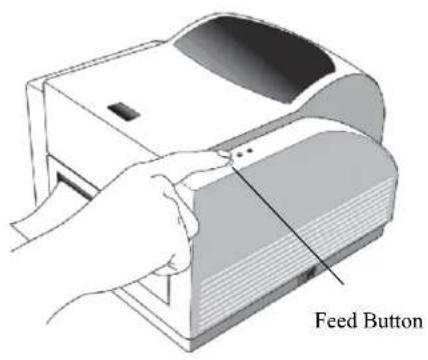
- Close the top cover and turn on the printer or press the feed button if the printer is already on.
25
A Series User's Manual
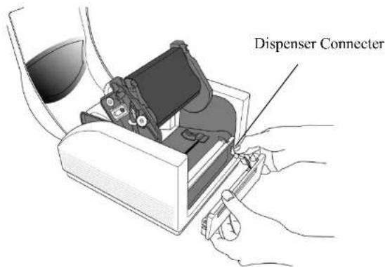
Peel Off Mode
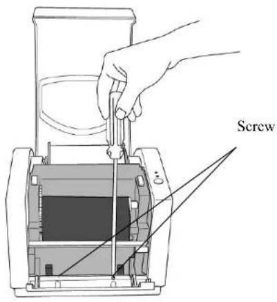
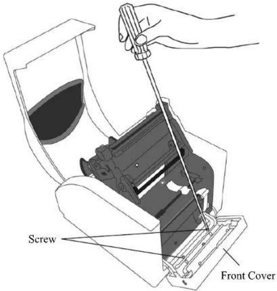
- Unscrew the two screws behind the front cover.
- Remove the front cover.
26
A Series User's Manual
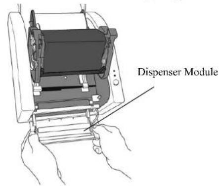
- Plug in the dispenser connector.
- Mount the dispenser module.
27
A Series User's Manual
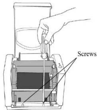
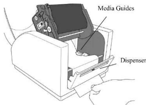
- Secure the two screws behind the front cover.
- Lead the labels through the media guides and dispenser.
28
A Series User's Manual
- Press down the print head module firmly until you hear a snap.
- Close the top cover and turn on the printer or press the feed button if the printer is already on.
29
A Series User's Manual
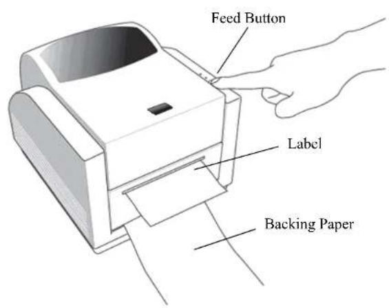
- Press the feed button and the label backing paper will come out from the slot under dispenser.
Note: The feed button does not make the printer peel.
Peeling occurs only when the software is properly set.
30
A Series User's Manual
Cutter Mode
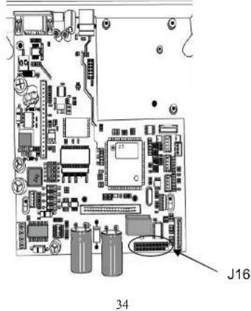
Note: For cutter mode you must first install the cutter and cutter baby board to J16 on the main board
- Turn off the POWER switch.
- Unscrew the two screws behind the front cover.
- Remove the front cover.
31
A Series User's Manual
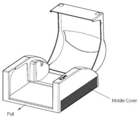
- Loose the 2 screws on the printer bottom.
- Pull out front side of "Middle Cover" then remove it from "Bottom".
- Take out "Middle Cover".
32
A Series User's Manual
33
A Series User's Manual
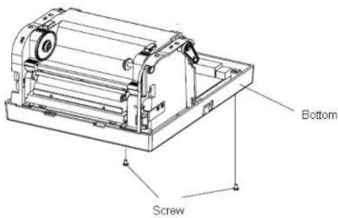
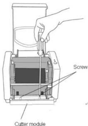
- Remove the whole print head assembly by releasing the 4 screws at its feet.
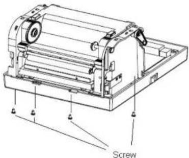
- Plug the cutter baby board to J16 on the main board.
A Series User's Manual
- Reattempt the print head assembly by securing the 4 screws and pull the front side of "Middle Cover" to put it back.
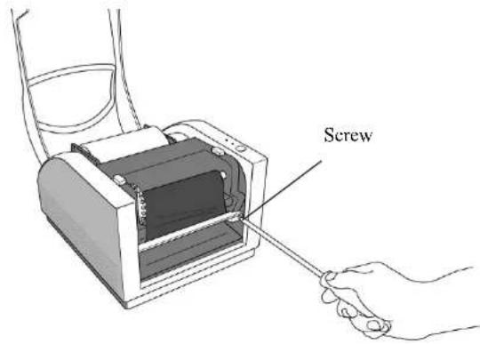
- Screw the 2 screws on the printer bottom.
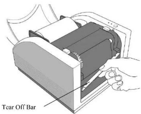
- Unscrew the screw on the printer module.
- Remove the tear off bar.
35
A Series User's Manual
- Plug in the cutter connector
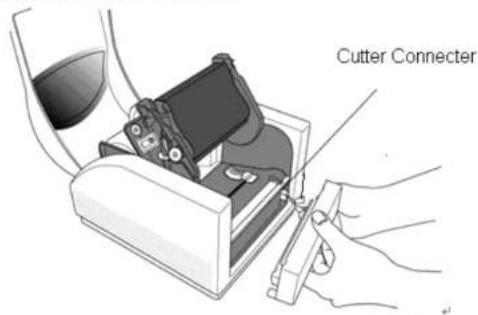
- Mount Cutter module, and install cutter module completely.
36
A Series User's Manual
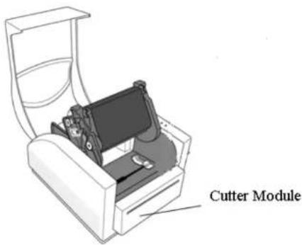
- Lead the label through the media guides and cutter slot.
- Press down the print head module firmly on both sides until you hear a snap.
37
A Series User's Manual
Note: The feed button does not make the printer cut. Cutting occurs only when the software is properly set.
A Series User's Manual
Configuration and Configuration
This section discusses calibration, printing configuration and resetting the printer to factory defaults.
Performing Calibration and a Configuration Report
- Make sure the media is properly loaded and the top cover of the printer is closed.
- Turn off the printer power.
- Press and hold the FEED button while turning on the power, until the printing motor is activated.
- Media Calibration will be performed while the printer automatically feeds the label stock for a certain length; then the printer motor suspends for one second and then prints out configuration/ self-test labels. Release the FEED button as soon as printer starts to print.
- The profile includes firmware version, ROM checksum, RS-232, thermal transfer/direct thermal settings, hardware configuration, and font types.
- At PPLB emulation, the printer enters character dump mode. To exit from dump mode, press the feed button again. (If you accidentally print the label without exiting from dump mode in advance, you need to turn on the printer or press feed button again to print normally.)
Important! You must always carry out calibration when changing media. Failure to do so will result in improper detection by the label sensor.
39
A Series User's Manual
Note: When using A-2240E or A-2240ME models, if you do not need configuration report, please press and hold the feed button while turning on the power, wait after about 20-25 seconds, release the feed button as soon as printer starts to feed a label.
Note: Revise the factory default settings that stored in flash, even if turn off the power source cannot be eliminated.
S
40
A Series User's Manual
Resetting Printer to Factory Defaults
- Turn on the printer and wait till both "Ready" indicator and "Power" indicator stay solid green.
- Press the "Feed" button for 5 seconds, and the "Ready" indicator and "Power" indicator will go off in order. (at this step, if the "FEED" button is pressed for 10 seconds, printer will reset first >> feed blank labels as media calibration >> and then print configuration/ self-test labels.)
- Once "Power" indicator becomes lit again, release the FEED button.
- "Ready" indicator will then become lit, too. At this moment, the printer has resumed its factory default settings
Note: Revise the factory default settings that stored in flash, even if turn off the power source cannot be eliminated.
Sensor Detection
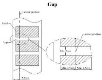
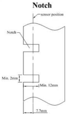
Detection Area of the Transmissive Sensor (edge)
The Transmissive Sensor (edge) is positioned at 7.7mm from the left edge of media. The detection area, as illustrated below.
A Series User's Manual
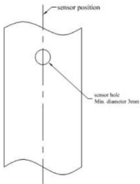
Detection Area of the Transmissive Sensor (centre)
The Transmissive Sensor (centre) is positioned at the centre of the media. The detection area, as illustrated below.
Oval Hole
43
A Series User's Manual
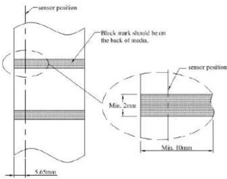
Detection Area of the Reflective Sensor
The reflective Sensor (edge) is positioned at 5.65mm from the left edge of media. The black mark minimum width (horizontal) should be 10mm on the left edge of media. The detection area, as illustrated below.
Black Mark
44
A Series User's Manual
Computer Connections
Note: You must insert the power supply's barrel connector into the power jack on the back of the printer before connecting communication cables.
This printer comes with a nine-pin Electronics Industries Association (EIA) RS-232 serial data interface, a USB interface and Ethernet option. You must supply the required interface cable for your application.
Note: This printer complies with FCC Rules and Regulations, Part 15, for Class A Equipment, for use with fully shielded six-foot data cables. Use of longer cables or unshielded cables may increase radiated emissions above Class A limits.
USB Interface Requirements
The Universal Serial Bus (USB) interface is version 2.0 and 1.1 compliant and provides a full-speed (12Mb/s) interface that is compatible with your existing PC hardware. The USB's "plug and play" design makes installation easy. Multiple printers can share a single USB port/hub.
Serial (RS-232) Interface Requirements
The required cable must have a nine-pin "D" type male connector on one end, which is plugged into the mating serial port located on the back of the printer. The other end of the signal interface cable connects to a serial port on the host computer.
For technical and pin-out information, please refer to the Technical Reference, Interface Specifications in this manual.
Serial Cabling Requirements
Data cables must be of fully shielded construction and fitted with metal or metalized connector shells. Shielded cables and connectors are required to prevent radiation and reception of electrical noise.
To minimize electrical noise pickup in the cable:
- Keep data cables as short as possible (6 ft or 1.83m recommended).
- Do not tightly bundle the data cables with power cords.
- Do not tie the data cables to power wire conduits.
Notes:
Default settings are included in the configuration report.
A-2240/A-3140/A-2240M
47
A Series User's Manual
Ethernet 10/100 Internal Printer Server Option
This connector is for Ethernet application; it is convenient to use several printers by Ethernet connector at the same time.
Notes:
When using Ethernet model printer, please wait till the Ready Indicator to stop blinking and then can start to use printer.
A-2240E/A-2240ME
48
A Series User's Manual
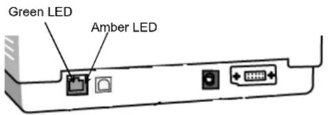
Ethernet Status/Activity Indicators
| LED Status Description | |
| Both Off No Ethernet link detected | |
| Green LED | Speed LED |
| On: 100 Mbps link Off: 10 Mbps link | |
| Amber LED | Link/Activity LED |
| On: link up Off: link down Flash: activity | |
Communicating with the Printer
The bundled printer driver can be applied to all applications under Windows XP/ Vista/ Windows 7, supporting 32-bit/ 64-bit operation systems. With this driver you can operate any popular Windows software applications including Argox Bartender UL label editing software or MS Word, etc., to print to this printer.
The following installation steps are based on A-2240 as an example. The screens included for these steps are taken from Windows XP; steps in other versions of operation systems are similar.
Installing a Plug and Play printer driver (for USB only)
Note:
We strongly recommend that you use the Seagull Driver Wizard instead of the Microsoft Windows Add Printer Wizard when installing and updating your Drivers by Seagull. (Even though the "Add Printer Wizard" is from Microsoft, it too easily performs a number of tasks incorrectly when updating existing drivers. It also badly handles the situation where a printer driver is already in use by a Windows application.)
- Turn off the printer. Plug the power cable into the power socket on the wall, and then connect the other end of the cable to printer's power socket. Connect the USB cable to the USB port on the printer and on the PC.
- Turn on the printer. If the printer supports Plug-and-Play, and you have successfully connected it using a USB cable, then the Windows Add Hardware Wizard will automatically detect the printer and display a dialog that allows you to install a driver. Click Cancel and do not install the driver using this wizard.
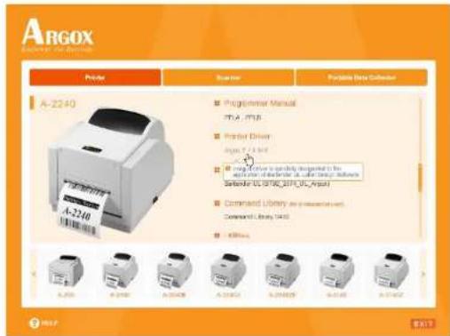
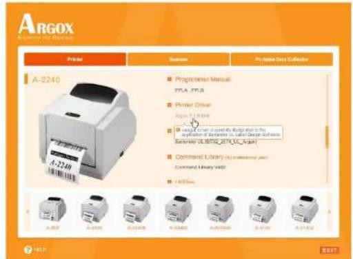
- Prepare the documentation and software CD-Rom from printer package and then install to CD-Rom drive of your computer. The CD-Rom will bring out the following prompt. Click "Go":

- Under A-2240 product selection prompt, choose Seagull Driver version and then start installation:
Instead of the flash prompt above, another way to install Seagull driver is to run the DriverWizard utility from the Installation Directory where the Seagull driver files are located.
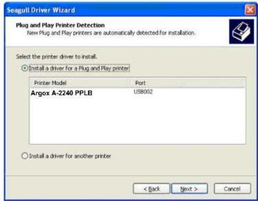
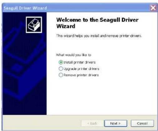
- On the Seagull Driver Wizard prompt, select the first radio button to "Install a driver for a Plug and Play printer":
- Enter Printer name (i.e. Argox A-2240D PPLB) and select "do not share this printer", and click "Next"
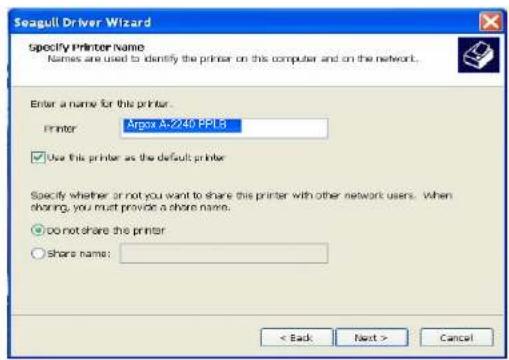
Then click "Next."
53
A Series User's Manual
54
A Series User's Manual
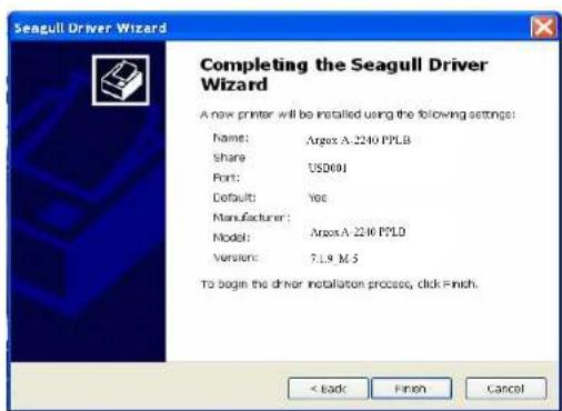
- Check all the data on the showing screen, if it is correct, click "Finish".
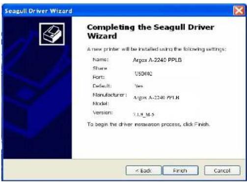
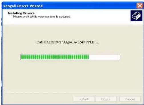
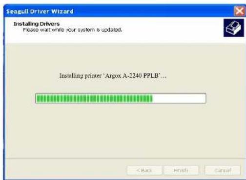
- After the related files have been copied to your system, click "Finish".
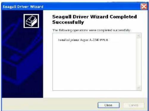
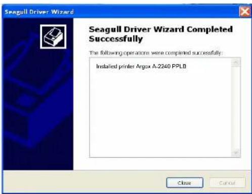
- After driver installation is complete, click "Close". The driver should now be installed.
57
A Series User's Manual
Installing the Printer Driver
-
Turn off the printer. Plug the power cable into the power socket on the wall, and then connect the other end of the cable to printer's power socket. Connect the USB cable, Serial cable, or Ethernet cable to the proper port on the printer and on your computer.
-
Prepare the documentation and software DVD-Rom from printer package and then install to DVD-Rom drive of your computer. The DVD-Rom will bring out the following prompt. Click "Go":

58
A Series User's Manual
- Under A-2240 product selection prompt, choose Seagull Driver version and then start installation:
Instead of the flash prompt above, another way to install Seagull driver is to run the DriverWizard utility from the Installation Directory where the Seagull driver files are located.
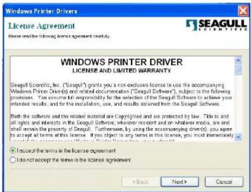
- On the prompt, Windows Printer Driver, select "I accept..." and click "Next".
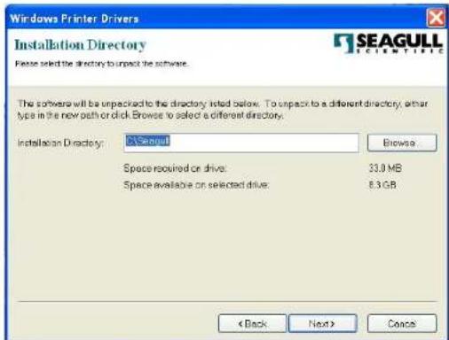
- Assign the directory to keep Seagull driver, (for example: C:\Seagull) and click "Next".
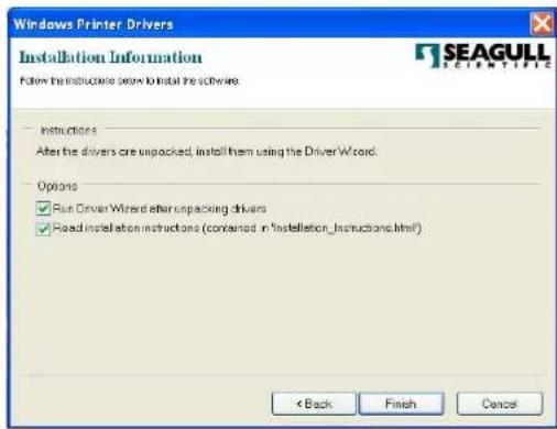
- Click "Finish".
61
A Series User's Manual
62
A Series User's Manual
7. Select Install printer drivers and Click "Next"
63
A Series User's Manual
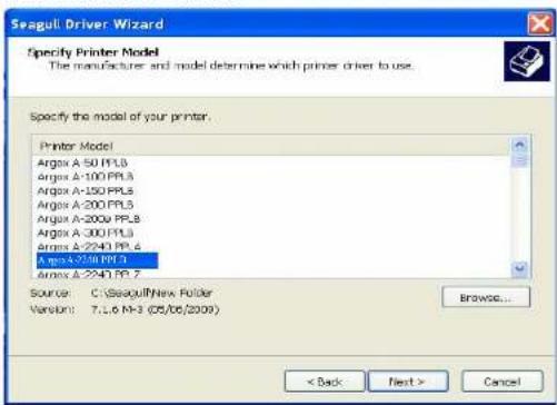
8. Select model & emulation - the following examples are based on model A-2240 PPLB:
64
A Series User's Manual
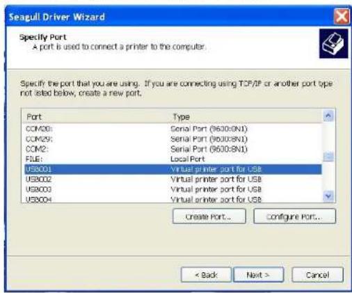
- Select the port of the printer and click "Next".
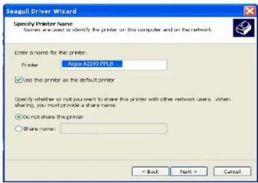
- Enter Printer name (i.e. Argox A-2240 PPLB) and select "do not share this printer", and click "Next".
65
A Series User's Manual
66
A Series User's Manual
- Check all the data on the showing screen, if it is correct, click "Finish".
- After the related files have been copied to your system, click "Finish".
67
A Series User's Manual
68
A Series User's Manual
- After driver installation is complete, click "Close". The driver should now be installed.
69
A Series User's Manual
Troubleshooting
Normally, when the printer is in not working properly, the "Power" LED blinks continuously, and printing and communication between the host and printer stops.
LED Diagnosis
If the Power and Ready LEDs are blinking, it means you may have a problem. To understand the problem, please check the Power and Ready LEDs and refer to the following solutions:
LED Indicators: Power and Ready LEDs blink at the same tempo
| Power LED | Ready LED |
| ON ON | |
| OFF OFF |
| Possible Problems | Solutions Remarks | |
| Miss-detect gap | Check the label pathCheck the label sensor | If you use a continuous label roll and run under Windows, select the continuous media. |
| Label stock out Supply the label roll | ||
| Label stock not installed | Install the label roll | |
| Label jam Recover the jam | ||
70
A Series User's Manual
LED Indicators: Power and Ready LEDs blink alternately
| Power LED | Ready LED |
| ON OFF | |
| OFF ON |
| Possible Problems | Solutions Remarks | |
| Ribbon out Supply the ribbon roll | Not applicable to direct thermal type. | |
| Ribbon jam Recover the jam | ||
| Ribbon sensor error | Replace ribbon sensor | |
LED Indicators: Only the Power LED blinks
| Power LED | Ready LED |
| ON ON | |
| OFF ON |
| Possible Problems | Solutions Remarks | |
| Serial IO error Check | the baud rate Serial interface only | |
| Memory full Add the extension RAM(flash memory card) | ||
| Cutter failed, or jam at cutter | Check the cutter Recover the jam | Occurs only when installing or setting the cutter |
| Hardware error Call for service | ||
71
A Series User's Manual
LED Indicators: Only the Ready LED blinks
| Power LED | Ready LED |
| ON ON | |
| ON OFF |
| Possible Problems | Solutions Remarks | |
| Print head too hot | Printing will stop until the print head cools to an acceptable printing temperature. When it does, the printer will automatically resume operation. | |
| Printer head module uncovered | Make sure that printer head module has been covered. |
72
A Series User's Manual
Miscellaneous
■ If the host shows "Printer Time out"
- Check if the communication cable (serial) is connected securely to your serial port on the PC and to the connector on the printer at the other end.
- Check if the printer power is turned on.
If the data has been sent, but there is no output from the printer. Check the active printer driver, and see if Seagull driver for your Windows system and the label printer has been selected.
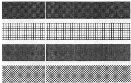
■ Vertical streaks in the printout usually indicate a dirty or faulty print head. (Refer to the following examples.)
natural_image
Abstract pattern of dark textured and white grid textures with no text or symbolsClean the print head. If the problem persists, replace the print head.
73
A Series User's Manual
■ Poor printout quality:
• The ribbon may not be qualified.
• The media may not be qualified.
- Adjust the Darkness (heat temperature).
- Slow down the print speed.
• Refer to the next chapter and clean the related spare parts.
Recovery
After correcting problems, simply press the panel button or restart the printer to continue your print jobs. Make sure the LEDs are not blinking and remember to resend your files.
74
A Series User's Manual
Caring for Your Printer
Adhesives and coatings of media can over time transfer onto the printer components along the media path including the thermal print head and media sensor. This build-up can accumulate dust and debris. Failure to clean the print head, media path, and media sensor could result in inadvertent loss off labels, label jams and possible damage to the printer.
Note: Turn off the printer before cleaning.
Cleaning
Clean the following components of the printer using a cotton bud dampened with alcohol. Do not soak the cotton bud excessively.
Media Sensor
Debris or dirt on the media sensor can cause a miss-read or unstable detection of the label gap. Clean with a cotton bud dampened with alcohol.
Thermal Print Head
Thermal paper stock and the ribbon release debris on the print head, which degrades printing quality. Clean the print head with methanol or isopropyl alcohol and a cotton bud. Do not touch the heater element with your fingers. Debris or dirt on the roller should be cleaned with alcohol.
TPH Cleaning Interval:
It's strongly recommended to regularly clean print heads at least when changing every one ribbon roll (in thermal transfer printing mode), or every one label roll (in direct thermal printing mode). In addition, if printers are operated under critical applications and environments, or it's found print quality is degraded, please clean print heads more frequently.
TPH Cleaning Material:
Surface of print head's heating element is very fragile. To prevent from any possible damage, please use soft cloth or cotton buds with "Ethanol" or "industry alcohol" to clean print head surface. It's strongly recommended to wear hand gloves during cleaning progress. Do not touch print head surface by bare hands or with any hard equipment. Water or spit should be kept away in case of corrosion on heating elements.
TPH Cleaning Direction:
When cleaning print head, please always wipe in One-Way Direction - from Left to Right only, or from Right to Left only, to clean "Heating Line" of print head gently without excessive stress. Do not wipe back and forth, to avoid dust, dirt, or ribbon residue on cleaning cotton would be attached onto print head again. (Please refer to below picture)
natural_image
Diagram of a printer with an open lid and internal components, showing no text or symbols.Special Caution:
Warranty of print heads will be void if print head serial number is removed, altered, defected, or made illegible, under every circumstance.
77
A Series User's Manual
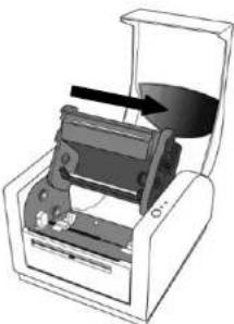
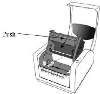
Replacing Thermal Print Head
- Turn off the power and wait for both LEDs to go off.
- Push the print head module and pull it down as shown by the two arrows below. This releases the print head module from the printer chassis.
78
A Series User's Manual
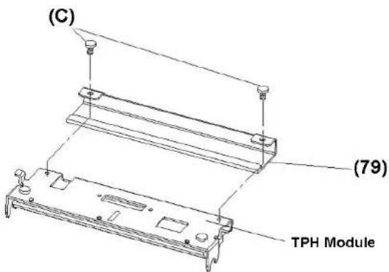
- Loosen the 2 screws(C) and take off COVER-TPH(79)
- Unplug the 2 print head cables from the connectors on the old TPH-module.
- Plug the 2 print head cable to the new TPH-module.
- Screw the COVER-TPH (79).
- Put the new "Print Head module" onto "Printer Chassis" with the same way, which you released it from "Printer Chassis
79
A Series User's Manual
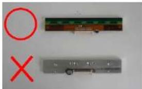
Important notice during TPH replacement
- Heater line should NOT be touched by bare hands to prevent any damage caused by ESD or corrosion.
- Surface of heaters should NOT be hit or scratched by sharp or hard things to prevent any damage by scratch.
- Residue or contamination should NOT be removed by a cutter to prevent any damage by dent or scratch.
- Connector side should NOT be touched when cleaning TPH to prevent delaminated solder between FPC and wafer. Ink-jet characters could be erased, if cleaning cloth was touched them on FPC or label.
- Heater surface should be free from any condensation.
- TPH should NOT be put heater surface down.
natural_image
Three electronic components: a green circuit board, a gray control box with a switch, and a red circle and X symbols (no readable text or labels)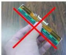
natural_image
Hand holding a small electronic device with a red X mark crossed out (no visible text or symbols)80
A Series User's Manual
Technical Reference
General Specifications
| Specification | A-2240A-2240ZA-2240EA-2240ZE | A-2240MA-2240ME | A-3140A-3140Z |
| Printing method | Direct Transfer/Thermal Transfer | ||
| Printing resolution | 203 dpi (8dots/mm) 300 dpi(12dots/mm) | ||
| Printing speed | Up to 5 ips (127mm/s) Up to 4 ips (102 mm/s) | ||
| Printing length | Max 100° (2540 mm) Max 50° (1270 mm) | ||
| Printing width | Max 4.1° (104mm) | ||
| Memory | 8MB DRAM(9MB user available)4MB Flash ROM(2MB user available) | 8MB DRAM(9MB user available)8MB Flash ROM(6MB user available) | |
| CPU type | 32 bit RISC microprocessor | ||
| Sensors | Media gap & black line Reflective sensor x 1 (movable)& Transmissive sensor x 1 (movable)Center Fixed transmissive x 1 / Head open switch / Ribbon end sensor | ||
| Operation interface | LED indicator(Power/Ready)x2, Button(Feed)x1 | ||
| Communication Interface | A-2240, A-2240Z, A-3140, A-3140Z, A-2240V, RS-232(Baud rate 2400 ~ 115200 bps), USB A-2240E, A-2240ME, RS-232(Baud rate 2400 ~ 115200 bps), USB, Ethernet | ||
| Fonts | Internal character sets standard5 alpha numeric fonts from 0.049*H ~ 0.23° H (1.25mm ~ 6.0mm)Internal fonts are expandable up to 24x24 4 direction 0 ~ 270 rotationSoft fonts are downloadableAbility to print any Windows True Type font easily | ||
| 1D Barcodes | PPLA:Code 39, UPC-A, UPC-E, Code 128 subset A/B/C, EAN-13, EAN-8, HBIC. Codabar, Plessey, UPC2, UPC5, Code 93, Postnet, UCC/EAN-128, UCC/EAN-128 K-MART, UCC/EAN-128 Random Weight, Telepen, FIL,Interleave 2 of 5 (Standard/with modulo 10 checksum/with human readable check digit/with modulo 10 checksum & shipping bearer bars), GS1 Data bar (RSS)PPLB:Code 39 Std. & Extended. UPC-A, UPC-E. Matrix 2 of 5, UPC-Interleaved 2 of 5,Code 39 with check sum digit, Code 93, EAN-13, EAN-8 (Standard, 2 /6digit add-on), Codabar, Postnet. Code'28 subset A/B/C, Code 128 UCC (shipping container code), Code 128 auto, UCC/EAN code 128 (GS1-128).Interleave 2 of 5, Interleaved 2 of 5 with check sum, Interleaved 2 of 5 with human readable check digit, German Postcode, Matrix 2 of 5,UPC Interleaved 2 of 5, EAN-13 2/5 digit add-on, UPC2 2/5 digit add-on, UPCE 2/5 digit add-on.GS1 Data bar (RSS)PPLZ:Code39, UPC-A, UPC-E, Postnet. Code128 subset A/B/C, Interleave 2 of 5, Interleaved 2 of 5 with check sum, Interleaved 2 of 5 with human readable check digit. Code 93, Code 39 with check sum digit, MSI, EAN-8, Codabar,Code 11, EAN-13, Plessey, GS1 Data bar (RSS), Industrial 2 of 5, Standard 2 of 5, Logmars | ||
| 2D Barcodes | PPLA-PPLZ - MaxiCode, PDF417,Data Matrix (ECC 200 only),QR code, Composite Codes, Aztec Barcode, Micro PDF417PPLB: MaxiCode, PDF417, Data Matrix (ECC 200 only), QR code, Composite Codes, Aztec Barcode | ||
| Graphic | PPLAPPLB: PCX, BMP, IMG, HEX,GDI, Binary raster(PPLB Only)PPLZ : GRF, Hex and GDI | ||
| Emulation | A-2240, A-2240E, A-2240M, A-2240ME, A-3140: PPLA/PPLBA-2240Z, A-3140Z: PPLZ | ||
| Software-Label editing | Windows Driver (XP/Vista/ Windows 7/8 ) BarTender | ||
| Software-Utility | Printer Utility, Font Utility | ||
| Media Type | Roll-feed, die-cut, continuous, fan-fold, tags, ticket in thermal paper or plain paper and fabric label | ||
| Media | Max Width:4.33"(110mm)Min Width:1"(25.4mm) Thickness:0.0025~0.01"(0.0635~0.254mm) Max roll Capacity(OD): 5"(127mm)Core size:1"(25.4mm) | ||
| Ribbon | Ribbon Width: 1~4" Ribbon roll – max OD: 1.45"(37mm) Ribbon Length: max 10cm Core size – ID: 0.5"(13mm) with notch Wax, Wax/Resin, Resin (Outside Ribbon) | ||
| Dimensions | W 201mm x H 179mm x L 245mm | ||
| Case Material | ABS and PC | ABS and PC with anti-microbial material, Conforms to JISZ2601 | ABS and PC |
| Weight | 2.2kgs | ||
| Power Source | Universal Switching Power Supply Input: 100V~240V±10%, 1.5A, 50~60Hz, Output: 24VDC, 2.4A | ||
| Operation Environment | Operation Temperature: 40°F-100°F (4°C-38°C), 0% - 90% non-condensing, Storage Temperature:-4°F-122°F (-20°C-50°C) | ||
| Optional Item | Cutter, Dispenser Kit, Stacker: RTC Card, ArgoKee | ||
| Agency Listing | CE, FCC, eTUVus, CCC, | ||
Notes:
- The bare core for the ribbon must be 11 cm in length. It should have two opposite slits at two ends. If the ribbon itself is less than 11 cm, it must be aligned with the bare core in the center when you install it.
Fonts, Bar Codes and Graphics Specification
The specifications of fonts, bar codes and graphics depends on the printer emulation. The emulations PPLA, PPLB and PPLZ are printer programming languages, through which the host can communicate with your printer.
Printer Programming Language A, PPLA
| Programming Language | PPLA |
| Internal fonts | 9 fonts with different point size6 fonts with ASD smooth font.Courier font with different symbol sets. |
| Symbol sets (Code pages) | Courier font symbol set: Roman-8, ECMA-94, PC,PC-A, PC-B, Legal, andPC437 (Greek), Russian. |
| Soft fonts Downloadable soft fonts | |
| Font size | 1x1 to 24x24 times |
| Character rotation | 0, 90, 180, 270 degree, 4 direction rotation |
| Graphics | PCX, BMP, IMG, HEX, GDI |
| Bar code types | Code 39, UPC-A, UPC-E,Code 128 subset A/B/C,EAN-13, EAN-8, HBIC, Codabar, Plessey, UPC2,UPC5, Code 93, Postnet, UCC/EAN-128,UCC/EAN-128 K-MART, UCC/EAN-128 RandomWeight, Telepen, FIM, Interleave 2 of 5(Standard/with modulo 10 checksum/with human readable check digit/with modulo 10 checksum & shipping bearer bars), GS1 Data bar (RSS),MaxiCode, PDF417,Data Matrix (ECC 200 only),QR code, Composite Codes, Aztec Barcode,Micro PDF417 |
Printer Programming Language B, PPLB
| Programming Language | PPLB |
| Internal fonts | 5 fonts with different point size |
| Symbol sets (Code pages) | 8 bits code page: 437, 850, 852, 860, 863, 865, 857, 861, 862, 855, 866, 737,851,869, 1252, 1250, 1251, 1253, 1254, 12557 bits code page: USA, BRITISH, GERMAN, FRENCH, DANISH, ITALIAN, SPANISH, SWEDISH and SWISS.(300dpi printer models support Code page 437,850, 852,860, 863,865,1254 only) |
| Soft fonts Downloadable soft fonts | |
| Font size | 1x1 to 24x24 times |
| Character rotation | 0, 90, 180, 270 degree, 4 direction rotation |
| Graphics | PCX, BMP, IMG, HEX, GDI, Binary raster |
| Bar code types | Code 39 Std. & Extended, UPC-A, UPC-E, Matrix 2 of 5, UPC-Interleaved 2 of 5,Code 39 with check sum digit, Code 93, EAN-13, EAN-8 (Standard, 2 /5digit add-on), Codabar, Postnet, Code128 subset A/B/C, Code 128 UCC (shipping container code), Code 128 auto, UCC/EAN code 128 (GS1-128), Interleave 2 of 5, Interleaved 2 of 5 with check sum, Interleaved 2 of 5 with human readable check digit, German Postcode, Matrix 2 of 5,UPC Interleaved 2 of 5, EAN-13 2/5 digit add-on, UPCA 2/5 digit add-on, UPCE 2/5 digit add-on, GS1 Data bar (RSS), MaxiCode, PDF417, Data Matrix (ECC 200 only), QR code, Composite Codes, Aztec Barcode |
85
A Series User's Manual
Printer Programming Language Z, PPLZ
| Programming Language | PPLZ |
| Internal fonts | 8 (A~H) fonts with different point size.8 AGFA fonts: 7 (P~V) fonts with fixed different point size (can't scale).1 (0) font with scaling point size. |
| Symbol sets (Code pages) | USA1, USA2, UK, HOLLAND, DENMARK,NORWAY, SWEDEN/FINLAND, GERMAN, FRANCE1, FRANCE2, ITALY, SPAIN, MISC,JAPAN, IBM850. |
| Soft fonts Downloadable soft fonts | |
| Font size | 1x1 to 10x10 times |
| Character rotation | 0, 90, 180, 270 degree, 4 direction rotation |
| Graphics | GRF, Hex and GDI |
| Bar code types | Code39, UPC-A, UPC-E, Postnet, Code128 subset A/B/C, Interleave 2 of 5, Interleaved 2 of 5 with check sum, Interleaved 2 of 5 with human readable check digit, Code 93, Code 39 with check sum digit, MSI, EAN-8, Codabar, Code 11, EAN-13, Plessey, GS1 Data bar (RSS), Industrial 2 of 5, Standard 2 of 5, Logmars, MaxiCode, PDF417,Data Matrix (ECC 200 only), QR code, Composite Codes, Aztec Barcode, Micro PDF417 |
86
A Series User's Manual
Interface Specifications
USB Interface
This is port complies with USB 2.0 Full Speed.
Connector Terminal Pin Assignment
| Pin | Signal Description | |
| 1 | VBUS 5V | |
| 2 | D - | Differential data signaling pair - |
| 3 | D + | Differential data signaling pair + |
| 4 | GND Ground | |
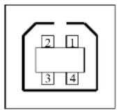
USB series "B" Receptacle Interface
87
A Series User's Manual
Serial
The RS232 connector on the printer side is a female, DB-9.
| Pin | Direction | Definition |
| 1 | Shorted to Pin 6 | |
| 2 | In RxData | |
| 3 | Out TxData | |
| 4 | N.C. | |
| 5 | Ground | |
| 6 | Shorted to Pin 1 | |
| 7 | Out RTS | |
| 8 | In CTS | |
| 9 | Out +5V |
Note : Pin 9 are reserved for KDU (keyboard device unit), therefore do not connect these pins if you are using a general host like a PC.
88
A Series User's Manual
Ethernet
The following port complies with Ethernet communication.
| Pin | Signal |
| 1 | Transmit+ |
| 2 | Transmit- |
| 3 | Receive+ |
| 4 | Reserved |
| 5 | Reserved |
| 6 | Receive- |
| 7 | Reserved |
| 8 | Reserved |
Connection with host
Host 25S Printer 9P Host 9S Printer 9P (PC or compatible) (PC or compatible)
| DTR 20 ...... | 1 DSR | DTR 4 ...... | 1 DSR |
| DSR 6 ...... | 6 DTR | DSR 6 ...... | 6 DTR |
| TX 2 ...... | 2 RX | TX 3 ...... | 2 RX |
| RX 3 ...... | 3 TX | RX 2 ...... | 3 TX |
| CTS 5 ...... | 7 RTS | CTS 8 ...... | 7 RTS |
| RTS 4 ...... | 8 CTR | RTS 7 ...... | 8 CTS |
| GND 7 ...... | 5 GND | GND 5 ...... | 5 GND |
Alternatively you can just connect the 3 wires in the following way.
Host 25S Printer 9P Host 9S Printer 9P (PC or compatible) (PC or compatible)
| TX 2 ...... | 2 RX | TX 3 ...... | 2 RX |
| RX 3 ...... | 3 TX | RX 2 ...... | 3 TX |
| GND 7 ...... | 5 GND | GND 5 ...... | 5 GND |
| pin 4 | pin 4 | ||
| pin 5 | pin 6 | ||
| pin 6 | pin 7 | ||
| pin 20 | pin 8 |
The simplest way to connect to other hosts (not PC compatible) or terminals is:
| Printer Terminal/Host | ||
| Pin 2- RxData | ...... | TxData |
| Pin 3- TxData | ...... | RxData |
| Pin 5- Ground | ...... | Ground |
In general, as long as the data quantity is not too large and you use Xon/Xoff as flow control, it will be problem free.
Baud rate: 2400, 4800, 9600(default), 19200, 38400, 57600, 115200 bauds.(programmable by command)
Data format: always 8 data bits, 1 start bit and 1 stop bit.
Parity: always non parity
Handshaking: XON/XOFF as well as CTS/RTS (hardware flow control).
If you run an application with the bundled printer driver under Windows and use the serial port, you should check the above parameters and set the flow control to "Xon/Xoff" or "hardware".
91
A Series User's Manual
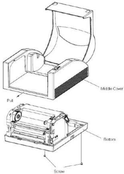
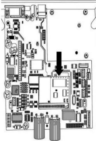
Appendix I - Installing the Extension Card
Extension Card designated for all optional extension modules. For example, RTC card and Add-on card.
Install the extension card into the printer as follows:
- Turn off the printer power.
- Remove the top cover.
- Release the two screws at the bottom of the base housing.
92
A Series User's Manual
- Remove the middle cover.
93
A Series User's Manual
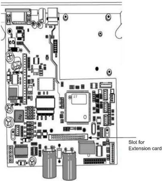
- Mount the extension card to J14 on the main board.
Note:
RTC card: Dip switch on DIP 5 should be put on OFF position.
Add-on card: Dip switch on DIP 5 should be put on On position.
natural_image
Pure electrical circuit lines without any symbols- Click back the middle cover.
- Secure the two screws for the base housing.
- Click the top cover into place.
94
A Series User's Manual