OS-2130DE - Printer Argox - Free user manual and instructions
Find the device manual for free OS-2130DE Argox in PDF.

User questions about OS-2130DE Argox
0 question about this device. Answer the ones you know or ask your own.
Ask a new question about this device
Download the instructions for your Printer in PDF format for free! Find your manual OS-2130DE - Argox and take your electronic device back in hand. On this page are published all the documents necessary for the use of your device. OS-2130DE by Argox.
USER MANUAL OS-2130DE Argox
natural_image
3D rendering of a gray industrial scanner or scanner device with control buttons and a logo (no visible text or symbols on the device itself)Website: http://www.argox.com
Table of Contents
Introduction......4
Proprietary Statement....4
Product Improvements 4
FCC Compliance Statement.... 4
Liability Disclaimer....4
Safety 5
Getting Started....6
Unpacking Printer....6
Package Contents....7
Printer Overview......8
Front View: OS-2130D and OS-2130DE 8
Rear View: OS-2130D 9
Rear View: OS-2130DE 10
Interior View I 11
Interior View II 12
Attaching Power 13
Loading Media 4
Preparing Media....4
Placing Media Roll 4
Printer Operations 8
Printing Media Calibration & Configuration...... 8
Steps to Start Media Calibration & Configuration ..... 8
Sample of Printer Configuration Label 9
Resetting Printer to Factory Defaults.... 11
Printer Controls and Indicators 12
Troubleshooting by LED and Buzzer Indicators
Diagnosis 16
Miscellaneous....20
Recovery 21
2
OS-2130D & OS-2130DE User's Manual
Communications 22
Interfaces and Requirements....22
USB Interface Requirements 22
Serial (RS-232) Interface Requirements....22
Ethernet 10/100 Internal Printer Server Option.....23
Ethernet Module Status Indicators....23
Communicating with the Printer 25
Installing a Plug and Play printer driver (for USB only) 26
Installing a Printer Driver (for other interfaces except USB)....32
Caring for Your Printer....39
Print Head Maintenance Guide....39
Cleaning Interval....39
Cleaning Material....39
Cleaning Direction ....40
Product Specification 41
General Specification....41
Fonts, Barcodes, and Graphics Specification .....45
Printer Programming Language PPLA....45
Printer Programming Language PPLB....46
Interface Specification....48
Cash Drawer....48
USB Interface 49
Serial Interface....49
Ethernet Interface ....51
Appendix I-Thermal Print Head Replacement....52
Appendix II-Cutter Installation ....54
Appendix III-Dispenser kit Installation ....58
3
OS-2130D & OS-2130DE User's Manual
Introduction
Proprietary Statement
This manual contains proprietary information of Argox Information Co., Ltd. It is intended solely for the information and use of parties operating and maintaining the equipment described herein. Such proprietary information may not be used, reproduced, or disclosed to any other parties for any other purpose without the expressed written permission of Argox Information Co., Ltd.
Product Improvements
Continuous improvement of products is a policy of Argox Information Co., Ltd. All specifications and signs are subject to change without notice.
FCC Compliance Statement
This equipment has been tested and found to comply with the limits for a Class A digital device, pursuant to Part 15 of the FCC Rules. These limits are designed to provide reasonable protection against harmful interference in a residential installation. This equipment generates, uses, and can radiate radio frequency energy and, if not installed and used in accordance with the instructions, may cause harmful interference to radio communications. However, there is no guarantee that the interference will not occur in a particular installation. If this equipment does cause harmful interference to radio or television reception, which can be determined by turning the equipment off and on, the user is encouraged to try to correct the interference by the following measures:
- Reorient or relocate the receiving antenna.
- Increase the separation between the equipment and the receiver.
- Connect the equipment into a different outlet on a different circuit.
- Consult the dealer or an experience Radio/TV technician for help.
This unit was tested with shielded cables on the peripheral devices. Shielded cables must be used with the unit to insure compliance. The user is cautioned that any changes or modifications not expressly approved by Argox Information Co., Ltd. could void the user's authority to operate the equipment.
Liability Disclaimer
Argox Information Co., Ltd. takes steps to assure that the company's published engineering specifications and manuals are correct; however, errors do occur. Argox Information Co., Ltd. reserves the right to correct any such errors and disclaims any resulting liability. In no event shall Argox Information Co., Ltd. or anyone else involved in the creation, production, or delivery of the accompanying product (including hardware and software) be liable for any damages whatsoever (including, without limitation, damages for loss of business profits, business interruption, loss of business information, or other pecuniary loss) arising out of the use of or the results
4
OS-2130D & OS-2130DE User's Manual
of use of or inability to use such product, even if Argox Information Co., Ltd. has been advised of the possibility of such damages.
CAUTION:
Any changes or modifications not expressly approved by the party responsible for compliance could void the user's authority to operate the equipment.
Safety

Supplemental Information: This device complies with the requirement of FCC Part 15 Rules. Operation is subject to the following two Conditions: (1) This device may not cause harmful interference, and (2) this device must accept any interference received, including interference that may cause undesired operation
INDUSTRY CANADA NOTICE:
This device complies with Industry Canada ICES-003 class A requirements.
Please only use adapters with the following electrical characteristics and are certified by current legislation. Using other adapters may damage the device and void the warranty also cause risks to the user.
Features Output: 24VDC, 2.4A

The manufacturer declares under sole responsibility that this product conforms to the following standards or other normative documents:
EMC: EN 55022:2006+A1:2007, class A
EN 55024:1998+A1:2001+A2:2003

Argox Information Co., Ltd certifies that the following products and/or components are compliant with the current requirements of the European Union Restriction on the use of Hazardous Substances (RoHS) Directive, 2002/95/EC.
5
OS-2130D & OS-2130DE User's Manual
Getting Started
Congratulations on choosing OS-2130D and OS-2130DE printers, made by Argox Information Co., a leader in the world-wide barcode industry. OS-2130D and OS-2130DE are ideally designed to easily bring more efficiency for your business. This manual will help you get to know your new printer and provide sufficient information needed.
Unpacking Printer
After receiving your printer, please check for possible shipping damage:
Inspect the outside of both the box and the printer for possible damage.
- Open the top cover of the printer to see if all parts are in order.
Note: If shipping damage has been discovered, contact your shipping company immediately to file a claim.
- Check whether you have received the following accessories together with the printer. If there is any item missing, please contact your local dealer.
6
OS-2130D & OS-2130DE User's Manual
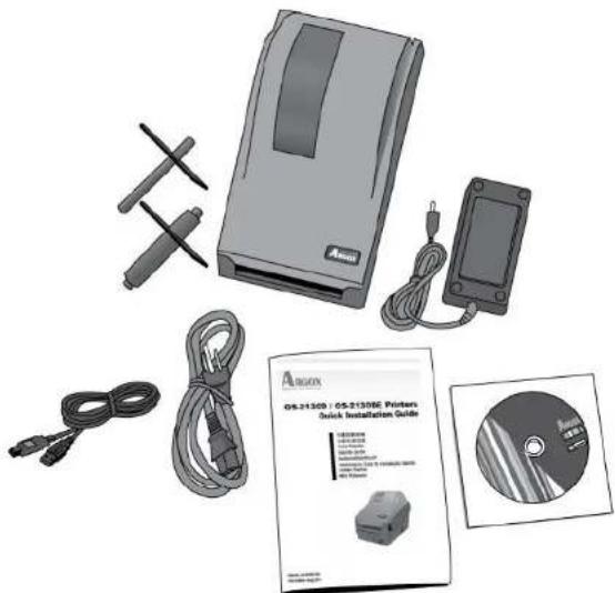
Package Contents
natural_image
Product display of an Amax 05-2130E printer with cable, earplifier, and CD cover (no visible text or symbols on main objects)- Quick Installation Guide
• CD ROM (Documentation & Software) - Power Cord
• Media Hanger & Media Shields - Printer
• Power Supply - USB cable
7
OS-2130D & OS-2130DE User's Manual
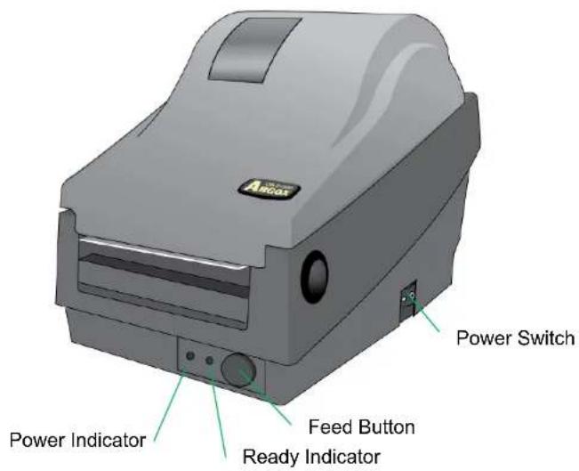
Printer Overview
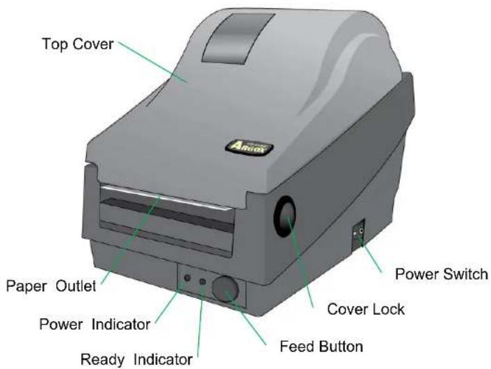
Front View: OS-2130D and OS-2130DE
8
OS-2130D & OS-2130DE User's Manual
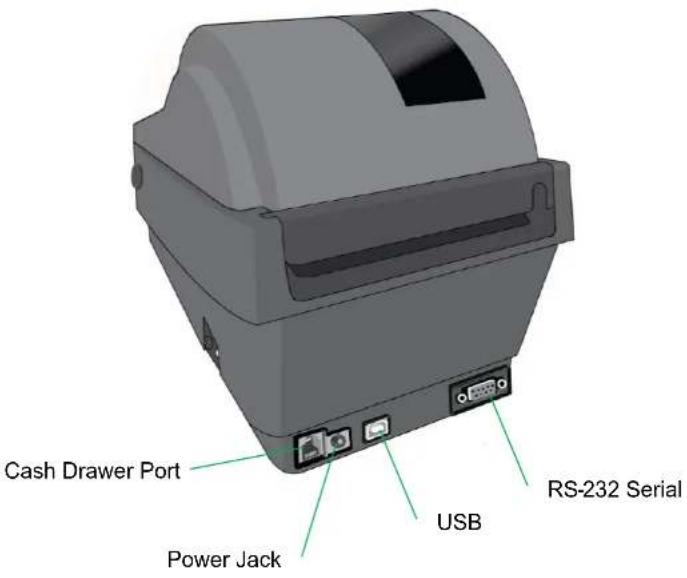
Rear View: OS-2130D
9
OS-2130D & OS-2130DE User's Manual
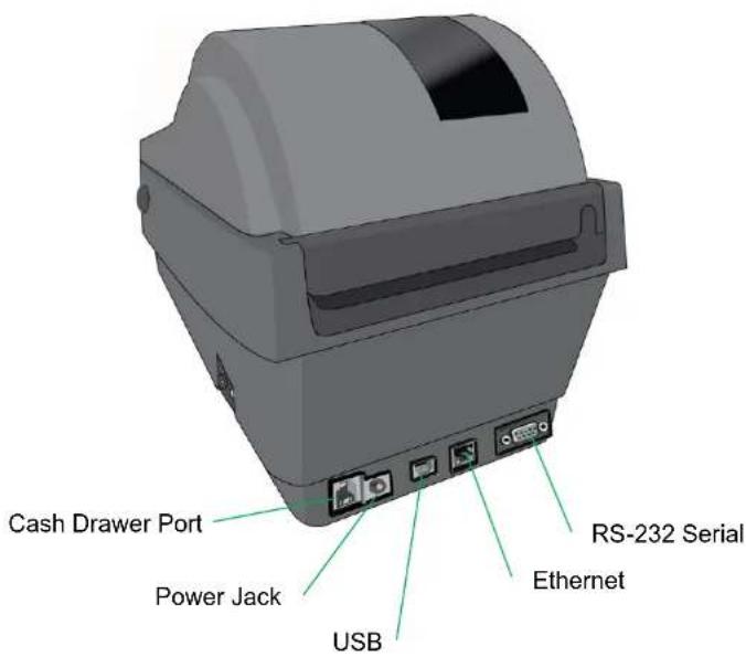
Rear View: OS-2130DE
10
OS-2130D & OS-2130DE User's Manual
Interior View I
11
OS-2130D & OS-2130DE User's Manual
Interior View II
12
OS-2130D & OS-2130DE User's Manual
Attaching Power
- Make sure the printer's power switch is in the off position (down) before conducting following actions.
- Insert the AC power cord into the power supply.
- Insert the power supply's power connector into the printer's power jack.
- Plug the other end of the power cord into an appropriate grounded AC electrical outlet.
Warning:
Do not operate the printer and power supply in an area where they might get wet.
OS-2130D
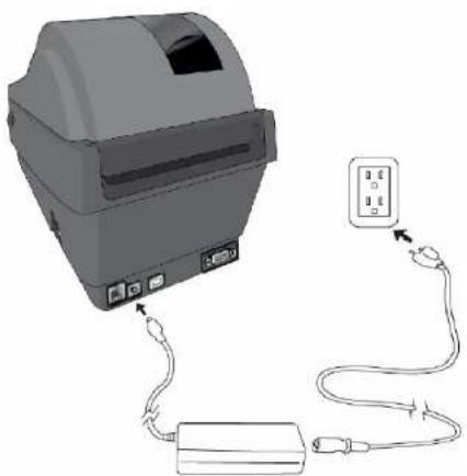
natural_image
Diagram of a printer connected to a power strip via cable, showing ports and wiring (no text or symbols present)13
OS-2130D & OS-2130DE User's Manual
OS-2130DE
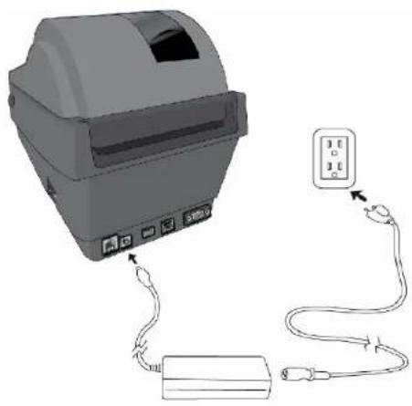
natural_image
Diagram of a printer with attached cable and connector, showing ports and wiring (no text or symbols)14
OS-2130D & OS-2130DE User's Manual
Loading Media
Preparing Media
In case media roll may become dirty or dusty during shipment, handling, or storage, firstly remove the outside length of media, which helps to avoid dragging adhesive or dirty media between the print head and platen roller. When loading media, it must be placed onto the media hangers.
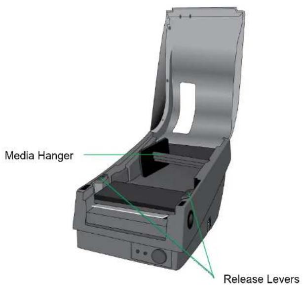
Placing Media Roll
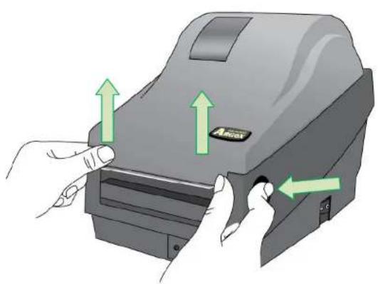
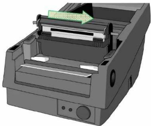
- Open Top Cover of the printer.
natural_image
Illustration of a printer with green arrows indicating press or movement (no text or symbols)4
OS-2130D & OS-2130DE User's Manual
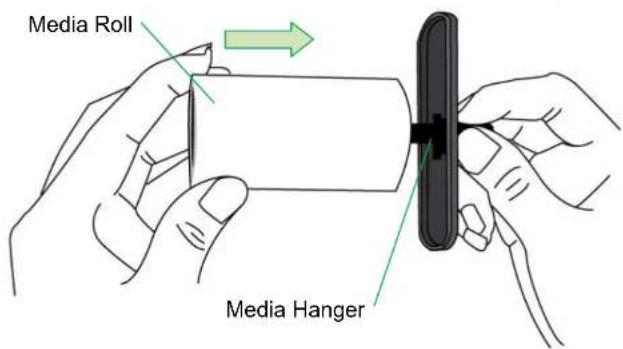
- Put the Media Hanger through media supply roll, and then centrally align with the two Media Shields to closely lean against the media supply roll.
5
OS-2130D & OS-2130DE User's Manual
- Locate the media supply roll into the Media Compartment of printer.
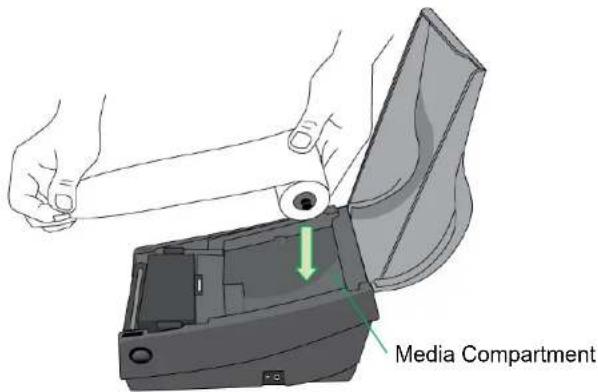
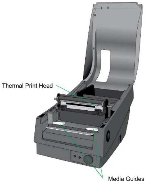
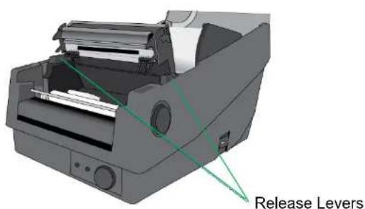
- Push the Release Levers to open the printer module.
4
OS-2130D & OS-2130DE User's Manual
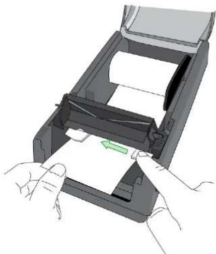
- Pull a short length of media till it reaches the Platen Roll of printer. Adjust the media guide at right margin, to make media left-alignment.
natural_image
Illustration of hands inserting a paper into a printer into a slot (no text or symbols visible)5
OS-2130D & OS-2130DE User's Manual
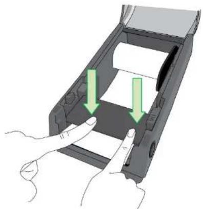
- Close the printer module and then press firmly at the both sides to properly latch until you hear a click.
natural_image
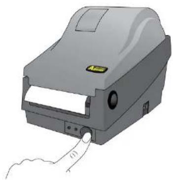
Illustration of hands inserting a card into a device (no text or symbols visible)- Press the FEED button to feed labels out of the printer.
natural_image
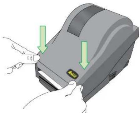
Illustration of a gray electronic device with a label and a finger pointing to it (no text or symbols on the device itself)- Close the top cover and turn on the printer.
natural_image
Illustration of hands inserting a device into a slot with green arrows indicating direction (no text or symbols)6
OS-2130D & OS-2130DE User's Manual
7
OS-2130D & OS-2130DE User's Manual
Printer Operations
Printing Media Calibration & Configuration
Before connecting the printer to your computer, to make sure that the printer works properly, conduct media calibration and print a self-test/ configuration label.
Steps to Start Media Calibration & Configuration
- Make sure the media is properly loaded and the top cover of the printer is closed.
- Turn off the printer power.
- Press and hold the FEED button while turning on the power, until printer motor is activated.
- Media Calibration will be performed while the printer automatically feeds the label stock for a certain length; then the printer motor suspends for one second and then prints out a configuration profile. Release the FEED button as soon as printer starts to print.
Note:
If printer is with Argox PPLB printer language, printer will enter Dump mode after printing configuration. In Dump mode, all characters will be printed in 2 columns: the right shows characters received from your system, and the left are the corresponding hexadecimal values of the characters. It allows users or engineers to verify and debug the program.
To return to normal operation mode from Dump mode, press the FEED button again. Another way is to turn off printer power, and then restart printer.
8
OS-2130D & OS-2130DE User's Manual
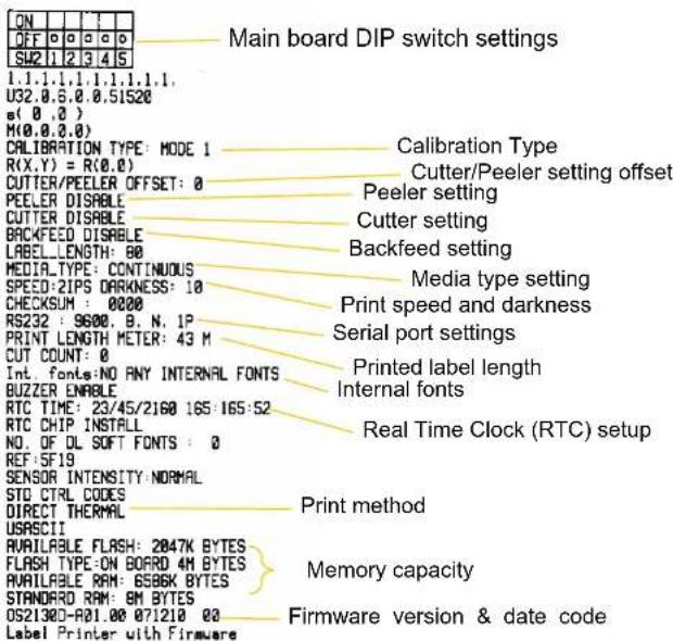
Sample of Printer Configuration Label
R8/E94/PC/PCA/PCB
Courier Fonts:
ASD font 18 points
ASD font 14 points - 01
ASD font 12 points - 012345
ASD font 10 points - 0123456789
ASD font 8 points - 0123456789 ABCDEF
0123456789
INT. FONT 7 01234567
INT. FONT 6
INT. FONT 5 0123456
INT. FONT 4 0123456
INT. FONT 3 0123456789 AB
INT. FONT 2 0123456789 ABCDEFGHIJ
INT, FONT 1 0123456700 ABCDEFGHJKYZ
INT. FORM 8. RISPARETRO RECOFTIC,0972
- Print head test pattern
9
OS-2130D & OS-2130DE User's Manual
Resetting Printer to Factory Defaults
Follow the steps below to reset printer to default settings:
- Turn on the printer and wait for 5 or more seconds.
- Press the "FEED" button for 10 seconds, and the "Ready" indicator and "Power" indicator will go off in order.
- Once "Power" indicator becomes lit again, release the FEED button.
- "Ready" indicator will then become lit, too. At this moment, the printer has resumed its factory default settings.
Note:
The printer factory default settings are stored in printer's flash; these settings remain stored, without being erased even the printer power is disconnected.
Printer Controls and Indicators
12
OS-2130D & OS-2130DE User's Manual
The following table explains printer controls and indicators' functions to help understanding LED indications and printer status:
| Control / Indicator | Function |
| Power Switch | On: turns on normal operation (at “I” position)Off: turns off power ( at “O” position)Note:Turn power off before connecting or disconnecting cables |
| Power LED | Off: Printer power offGreen: Printer power onIt will start blinking while “Media Out”, “Media Gap Not Found” has been detected.Once printer cutter mode has been enabled, when Cutter is jammed with paper or Cutter is not installed, POWER indicator will blink.When RS-232 communication error is detected, POWER indicator will blink. |
13
OS-2130D & OS-2130DE User's Manual
| Ready LED | When printer is started, the READY indicator will blink. In Ethernet model, the READY indicator will blink for several seconds to wait till and stop blinking when Ethernet Card is ready.When printer receives data from host PC, READY indicator will start blinking.READY indicator will blink when printing is paused.It will start blinking while “Media Out”, “Media Gap Not Found” has been detected.It will blink as soon as the printer module is opened.Note:When the print head is over-heated, printer’s thermal protection function will be activated and make READY LED blink to indicate printer is in PAUSE status to wait till print head has been cooled down. The printing tasks sent previously will be resumed automatically later. |
| Feed Button | Press to advance the label media to the first printing position.Press during printing to make printer "pause".Press and hold while switching on the power to conduct media calibration and print out a configuration profile.To resume printing after "Media Out" errors have been resolved. |
Troubleshooting by LED and Buzzer Indicators Diagnosis
Normally, when the printer is in not working properly, the "Power" LED blinks continuously, and printing and communication between the host and printer stops. Refer to LED indications listed below to understand possible solutions to resolve the problems printer may run into.
LED Indicators: Power and Ready LEDs blink at the same tempo
| Power LED Ready LED | |
| ON ON | |
| OFF OFF | |
| Possible Problems | Solutions Remarks | |
| Media sensor cannot index label gaps | Check the label path Check the label sensor | If a continuous label roll is in use, set “continuous media” printing in driver settings or commands. |
| Media out Install a new label roll | ||
| Paper jam Recover the jam | ||
16
OS-2130D & OS-2130DE User's Manual
LED Indicators: Only the Power LED blinks
| Power LED Ready LED | |
| ON ON | |
| OFF ON | |
| Possible Problems | Solutions Remarks | |
| Serial IO error Check | serial baud rate at both of your system and the printer. | For serial interface only |
| Cutter has failed, or there is paper jam inside the cutter. | Check the cutter or recover paper jam. | Only applicable when cutter mode to cutter mode. |
| Other possible hardware errors. | Contact the reseller for further service. | |
LED Indicators: Only the Ready LED blinks
| Power LED Ready LED | |
| ON ON | |
| ON OFF | |
| Possible Problems Solutions | |
| Print head needs to cool down | Printing will stop until the print head cools to normal printing temperature.Once it completes, the printer will automatically resume the printing tasks sent previously. |
17
OS-2130D & OS-2130DE User's Manual
| Printer is in PAUSE status | Press FEED button to resume printing. |
| Printer is receiving data | As soon as all the data has been received, Ready LED will stay solid green and automatically resume normal operation. |
The printer has built-in monitors for the status. The status and error indications will be displayed via the front panel LED indicators and the alert buzzer. Generally, when a malfunction or an abnormal condition is detected, the alert buzzer will beep for three times, and the ERROR LED will also blink. Below list shows the buzzer and LED indications corresponding to various errors.
| Situation | Buzzer Alert | Blinking LED | Description |
| MEDIA OUT | YES | READY POWER | Both LEDs blink synchronously. The media is not installed or used up. Printer fails to detect the media gap. |
| CUTTER FAILURE | YES POWER | Cutter failed or jammed at cutter. | |
| MEMORY FULL | YES POWER | The full printer buffer is caused by the loaded soft fonts, graphics or forms. Check the format of these data. Call for service | |
Note:
The alert buzzer can be disabled by Printer Utility.
Miscellaneous
If the host shows "Printer Time out":
- Check if the communication cable (serial) is connected securely to your serial port on the PC and to the connector on the printer at the other end.
- Check if the printer power is turned on.
If the data has been sent, but there is no output from the printer. Check the active printer driver, and see if Seagull driver for your Windows system and the label printer has been selected.
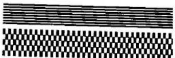
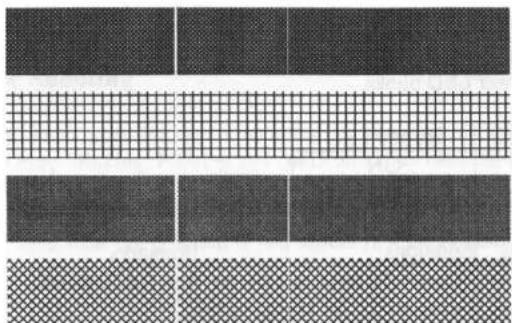
Vertical streaks in the printout usually indicate a dirty or faulty print head. (Refer to the following examples.)
natural_image
Grid-patterned fabric swatches with varying textures and shades (no text or symbols)Clean the print head. If the problem persists, replace the print head.
Poor printout quality:
• The media may not be qualified.
20
OS-2130D & OS-2130DE User's Manual
- Adjust the Darkness (heat temperature).
- Slow down the print speed.
• Refer to the next chapter and clean the related spare parts.
Recovery
After correcting problems, simply press the panel button or restart the printer to continue your print jobs. Make sure the LEDs are not blinking and remember to resend your files.
21
OS-2130D & OS-2130DE User's Manual
Communications
Interfaces and Requirements
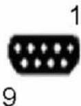
Argox OS-2130D and OS-2130DE printers come with a nine-pin Electronics Industries Association (EIA) RS-232 serial data interface, a USB interface, Cash drawer interface and Ethernet. A variety of interface options are suitable for versatile applications:
OS-2130D: Cash drawer, USB, and Serial interfaces
OS-2130DE: Ethernet, Cash drawer, USB, and Serial interfaces
Note:
- You must insert the power supply's barrel connector into the power jack on the back of the printer before connecting communication cables.
- This printer complies with FCC Rules and Regulations, Part 15, for Class A Equipment, for use with fully shielded six-foot data cables. Use of longer cables or unshielded cables may increase radiated emissions above Class A limits.
USB Interface Requirements
The Universal Serial Bus (USB) interface is version 2.0 and 1.1 compliant and provides a full-speed (12Mb/s) interface that is compatible with your existing PC hardware. The USB's "plug and play" design makes installation easy. Multiple printers can share a single USB port/hub.
Serial (RS-232) Interface Requirements
22
OS-2130D & OS-2130DE User's Manual
The required cable must have a nine-pin "D" type male connector on one end, which is plugged into the mating serial port located on the back of the printer. The other end of the signal interface cable connects to a serial port on the host computer.
Ethernet 10/100 Internal Printer Server Option
This connector is for Ethernet application; it is convenient to use several printers by Ethernet connector at the same time.
Note:
When using Ethernet model printer, please wait till the Ready Indicator to stop blinking, before starting printer operations.
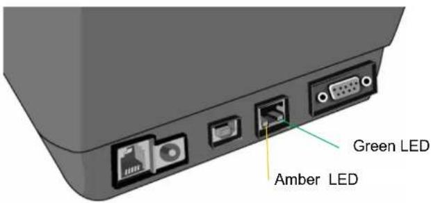
Ethernet Module Status Indicators
| LED Status | Description | |
| Both Off | No Ethernet link detected. | |
| Blinking | The printer waits for printer ready.It will take about 20 seconds to be ready. | |
| Green | Speed LED | On: 100 Mbps linkOff: 10 Mbps link |
| Amber | Link/Activity LED | On: link upOff: link downFlash: activity |
OS-2130DE Ethernet LED Indicators:
23
OS-2130D & OS-2130DE User's Manual
Communicating with the Printer
The bundled printer driver can be applied to all applications under Windows 2003/ XP/ Vista/ Windows 7, supporting 32-bit/ 64-bit operation systems. With this driver you can operate any popular Windows software applications including Argox Bartender UL label editing software or MS Word, etc., to print to this printer.
The following installation steps are based on OS-2130D as an example. The screens included for these steps are taken from Windows XP; steps in other versions of operation systems are similar.
24
OS-2130D & OS-2130DE User's Manual
25
OS-2130D & OS-2130DE User's Manual
Installing a Plug and Play printer driver (for USB only)
Note:
We strongly recommend that you use the Seagull Driver Wizard instead of the Microsoft Windows Add Printer Wizard when installing and updating your Drivers by Seagull.
(Even though the "Add Printer Wizard" is from Microsoft, it too easily performs a number of tasks incorrectly when updating existing drivers. It also badly handles the situation where a printer driver is already in use by a Windows application.)
- Turn off the printer. Plug the power cable into the power socket on the wall, and then connect the other end of the cable to printer's power socket. Connect the USB cable to the USB port on the printer and on the PC.
- Turn on the printer. If the printer supports Plug-and-Play, and you have successfully connected it using a USB cable, then the Windows Add Hardware Wizard will automatically detect the printer and display a dialog that allows you to install a driver. Click Cancel and do not install the driver using this wizard.
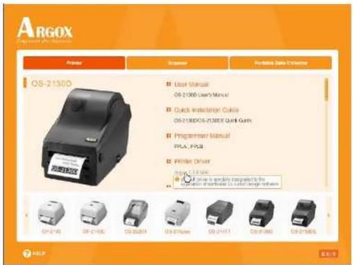
- Prepare the documentation and software CD-Rom from printer package and then install to CD-Rom drive of your
26
OS-2130D & OS-2130DE User's Manual
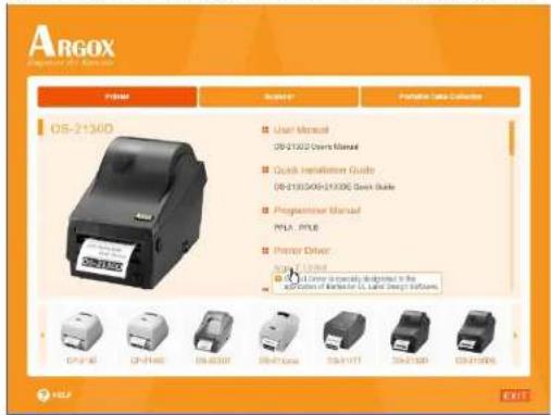
computer. The CD-Rom will bring out the following prompt. Click "Go":

- Under OS-2130D/OS-2130DE product selection prompt, choose Seagull Driver version and then start installation:
27
OS-2130D & OS-2130DE User's Manual
Instead of the flash prompt above, another way to install Seagull driver is to run the DriverWizard utility from the Installation Directory where the Seagull driver files are located.
- On the Seagull Driver Wizard prompt, select the first radio button to "Install a driver for a Plug and Play printer":
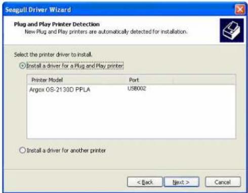
Then click "Next."
28
OS-2130D & OS-2130DE User's Manual
29
OS-2130D & OS-2130DE User's Manual
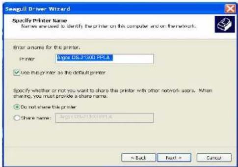
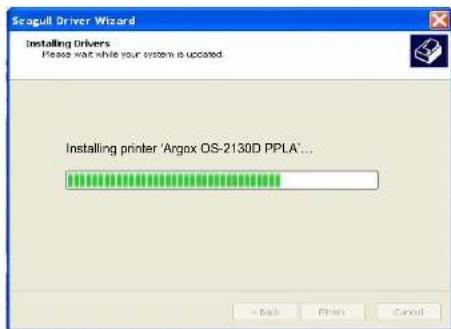
- Enter Printer name (i.e. Argox OS-2130D PPLA) and select "do not share this printer", and click "Next"
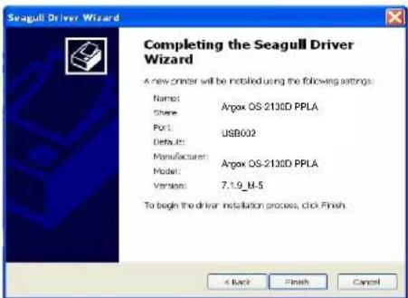
- Check all the data on the showing screen, if it is correct, click "Finish".
30
OS-2130D & OS-2130DE User's Manual
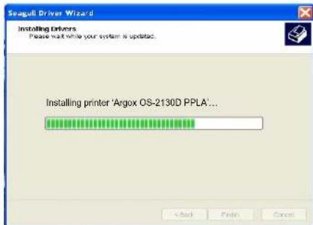
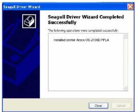
- After the related files have been copied to your system, click "Finish".
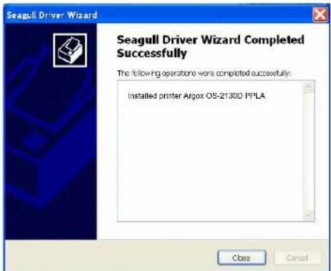
- After driver installation is complete, click "Close". The driver should now be installed.
31
OS-2130D & OS-2130DE User's Manual
Installing a Printer Driver (for other interfaces except USB)
- Turn off the printer. Plug the power cable into the power socket on the wall, and then connect the other end of the cable to printer's power socket. Connect the Parallel cable, Serial cable, or Ethernet cable to the proper port on the printer and on your computer.
- Prepare the documentation and software CD-Rom from printer package and then install to CD-Rom drive of your computer. The CD-Rom will bring out the following prompt. Click "Go":

32
OS-2130D & OS-2130DE User's Manual
- Under OS-2130D/OS-2130DE product selection prompt, choose Seagull Driver version and then start installation:
Instead of the flash prompt above, another way to install Seagull driver is to run the DriverWizard utility from the Installation Directory where the Seagull driver files are located.
33
OS-2130D & OS-2130DE User's Manual
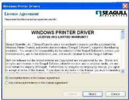
- On the prompt, Windows Printer Driver, select "I accept..." and click "Next".
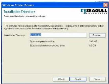
- Assign the directory to keep Seagull driver, (for example: C:\Seagull) and click "Next".
34
OS-2130D & OS-2130DE User's Manual
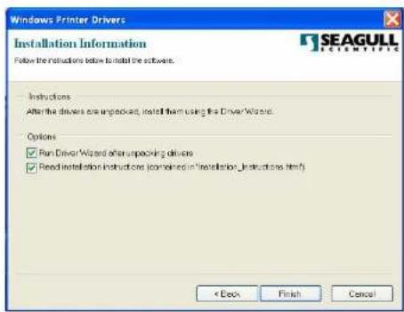
- Click "Finish".
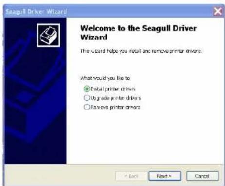
- Select Install printer drivers and Click "Next"
35
OS-2130D & OS-2130DE User's Manual
- Select model & emulation - the following examples are based on model OS-2130D PPLA:
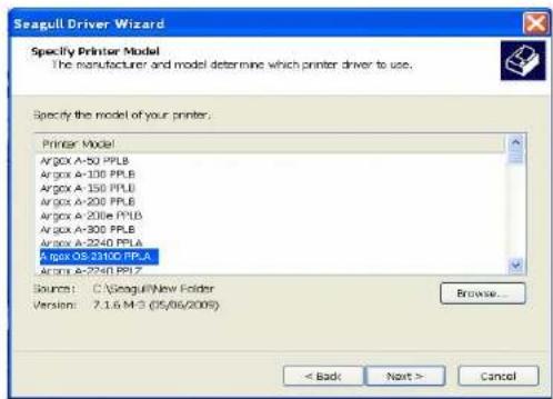
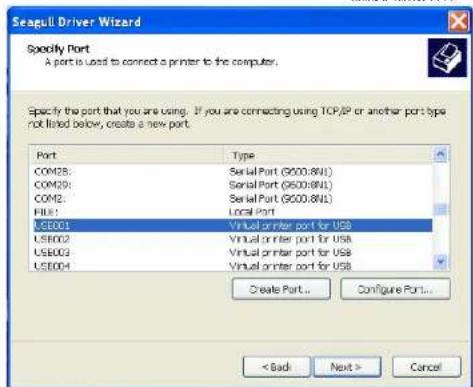
- Select the port of the printer and click "Next".
36
OS-2130D & OS-2130DE User's Manual
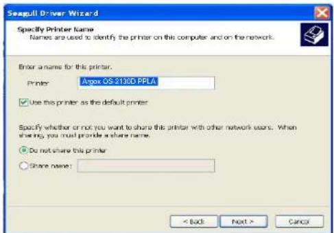
- Enter Printer name (i.e. Argox OS-2130D PPLA) and select "do not share this printer", and click "Next".
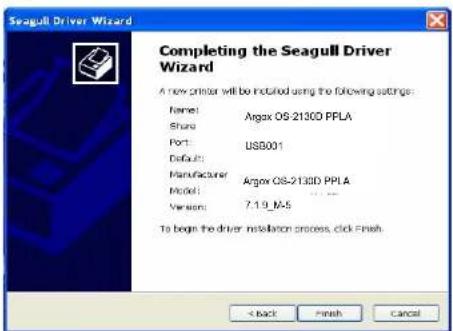
- Check all the data on the showing screen, if it is correct, click "Finish".
37
OS-2130D & OS-2130DE User's Manual
- After the related files have been copied to your system, click "Finish".
- After driver installation is complete, click "Close".
The driver should now be installed.
38
OS-2130D & OS-2130DE User's Manual
Caring for Your Printer
Print Head Maintenance Guide
To keep the Print Head remain in the best conditions and efficiency and to extend duration for use, regular cleaning action is needed:
Note: Always switch off printer power before cleaning.
Cleaning Interval
It's strongly recommended to regularly clean print heads at least when changing every one label roll (in direct thermal printing mode). In addition, if printers are operated under critical applications and environments, or if it's found that print quality is degraded, please clean print heads more frequently.
Cleaning Material
Surface of print head's heating element is very fragile. To prevent from any possible damage, please use the Printhead Cleaning Pen or soft cloth/ cotton buds with "Ethanol" or "industry alcohol" to clean print head surface.
It's strongly recommended to wear hand gloves during cleaning progress.
Do not touch print head surface by bare hands or with any hard equipment.
Water or spit should be kept away in case of corrosion on heating elements.
39
OS-2130D & OS-2130DE User's Manual
Cleaning Direction
When cleaning the print head, always wipe in One-Way Direction - from Left to Right only, or, from Right to Left only, to clean "Heating Line" of print head gently without excessive stress.
Do not wipe back and forth, to avoid dust or dirt on cleaning cotton would be attached onto print head again.
natural_image
3D rendering of a printer with a green arrow indicating a paper edge (no text or symbols visible)Special Caution:
Warranty of print heads will be void if print head serial number is removed, altered, defected, or made illegible, under every circumstance.
40
OS-2130D & OS-2130DE User's Manual
Product Specification
General Specification
| Specification | OS-2130D OS-2130DE |
| Print method Direct | thermal |
| Printing resolution 2 | 03 DPI (8 dots/mm) |
| Printing speed 2ips | ~ up to 4ips (51~102mm/s) |
| Printing length Max | 100"(2540mm) |
| Printing width Max | 2.83" (72mm), Min 1"(25.4mm) |
| Memory 8MB SDRAM | AM(6MB user available)4MB Flash ROM(2MB user available) |
| CPU type 32 bit RISC microprocessor 100MHz | |
| Sensors Reflective | (Left side) |
| Operation interface | Button(Feed) x 1 |
| Communicationinterface | RS-232, USB, Cash drawer, Ethernet(optional) |
| Fonts | PPLA:Internal fonts:9 fonts with different point size6 fonts with ASD smooth font.Courier font with different symbol sets.)PPLB:Internal fonts: 5 fonts with different point size |
| Soft fonts and 2-byte Asian fonts are downloadableAbility to print any Windows True Type Font easily | |
41
OS-2130D & OS-2130DE User's Manual
| 1D barcodes PPLA: | Code 39 (standard/with checksum digit), Code 93 Interleaved 2of 5 (standard/with checksum digit/with human readable check digit), EAN-8, EAN-13,UPC-A,UPC-E, Postnet, Codabar, Code 128 subset A/B/C, UCC/EAN-128, UCC/EAN-128 K-MART, UCC/EAN-128 , Random Weight, Plessey, HBIC, Telepen, FIM, UPC2, UPC5, GS1 DataBarPPLB:Code 39 (standard/with checksum digit),Code 93 Interleaved 2 of 5 (standard/with checksum digit/with human readable check digit), EAN-8 (standard/2 digit add-on/5 digit add-on), EAN-13 (standard/2 digit add-on/5 digit add-on), UPC-A (standard/2 digit add-on/5digit add-on), UPC-E (standard/2 digit add-on/5 digit add-on), Postnet, Codabar, Code 128 subset A/B/C, Code 128 UCC (Shipping Container Code), Code 128 Auto, German, Postcode, Matrix 2 of 5, UCC/EAN 128, UPC Interleaved 2 of 5, GS1 Data Bar |
| 2D barcodes | PPLA/PPLB:MaxiCode, PDF417, Data Matrix (ECC 200 only),QR code, Composite codes |
| Graphics PPLA/PPLB | PCX, BMP, IMG, HEX,GDI, Binary raster(PPLB Only) |
| Emulation PPLA, PPLB | |
| Software-labelediting | Windows Driver (Win 2003/XP/Vista/Win 7)BarTender |
| Software-utility | Printer Utility、Font Utility |
| Media type Roll-feed | die-cut, continuous, fan-fold, tags, ticket in thermal paper |
| Media Max width 3.03" (77 mm)Min width 1" (25.4 mm)Max length 100" (2540mm)Min length:0.196" (5mm)Thickness 0.0025"~0.01" (0.0635mm ~0.254mm)Max roll capacity core 0.5" OD 4.3"(109 mm),core 1" OD 4" (102 mm)Core size 0.5"(12.7mm) and 1"(25.4mm) ID | |
| Dimensions W 134 x H 163 x L 228 mm | |
| Weight 1.2kgs | |
| Power Source | 100V~240V,1.8A, 50~60Hz Input24V, 2.5A Typical, Output |
| Operation Environment | Operation Temperature: 40°F~100°F (4°C~38°C), 10% ~ 90% non-condensing, Storage Temperature: -4°F~122°F (-20°C~50°C) |
| Other Buzzer internal | RTC internalNote: RTC Lithium Battery Specification CR2032, +3V, 225mAh |
| Optional Items | Rotary CutterGuillotine CutterDispenser kitExternal 8"OD media stackerArgoKee |
Fonts, Barcodes, and Graphics Specification
The specifications of fonts, bar codes and graphics depends on the printer emulation. The emulations PPLA and PPLB are printer programming languages, through which the host can communicate with your printer.
Printer Programming Language PPLA
| Programming Language | PPLA |
| Internal fonts | 9 fonts with different point size6 fonts with ASD smooth font.Courier font with different symbol sets. |
| Symbol sets (Code pages) | Courier font symbol set: Roman-8, ECMA-94, PC,PC-A, PC-B, Legal, andPC437 (Greek), Russian. |
| Soft fonts | Downloadable soft fonts |
| Font size | 1x1 to 24x24 times |
| Character rotation | 0, 90, 180, 270 degree, 4 direction rotation |
| Graphics | PCX, BMP, IMG, HEX, GDI |
| Bar code types | Code 39 (standard/with checksum digit), Code 93Interleaved 2of 5 (standard/with checksum digit/with human readable check digit), EAN-8,EAN-13,UPC-A, UPC-E, Postnet, Codabar, Code 128 subset A/B/C, UCC/EAN-128, UCC/EAN-128 K-MART, UCC/EAN-128 , Random Weight, Plessey, HBIC, Telepen, FIM, UPC2, UPC5, GS1 Data Bar |
Printer Programming Language PPLB
| Programming Language | PPLB |
| Internal fonts | 5 fonts with different point size |
| Symbol sets (Code pages) | 8 bits code page: 437, 850, 852, 860, 863, 865, 857, 861, 862, 855, 866, 737,851,869, 1252, 1250, 1251, 1253, 1254, 12557 bits code page: USA, BRITISH, GERMAN, FRENCH, DANISH, ITALIAN, SPANISH, SWEDISH and SWISS. |
| Soft fonts Downloadable soft fonts | |
| Font size | 1x1 to 24x24 times |
| Character rotation | 0, 90, 180, 270 degree, 4 direction rotation |
| Graphics | PCX, BMP, IMG, HEX, GDI, Binary raster |
46
OS-2130D & OS-2130DE User's Manual
| Bar code types | Code 39 (standard/with checksum digit), Code 93 Interleaved 2 of 5 (standard/with checksum digit/with human readable check digit), EAN-8 (standard/2 digit add-on/5 digit add-on), EAN-13 (standard/2 digit add-on/5 digit add-on), UPC-A (standard/2 digit add-on/5digit add-on), UPC-E (standard/2 digit add-on/5 digit add-on), Postnet, Codabar, Code 128 subset A/B/C, Code 128UCC (Shipping Container Code), Code 128 Auto, German, Postcode, Matrix 2 of 5, UCC/EAN 128, UPC Interleaved 2 of 5, GS1 Data Bar |
47
OS-2130D & OS-2130DE User's Manual
Interface Specification
Cash Drawer
The following port complies with cash drawer communication.
| Pin $ignal |
| 1 Ground |
| 2 - |
| 3 Drawer _Back |
| 4 +24V |
| 5 Drawer_KICK2 |
| 6 Ground |

48
OS-2130D & OS-2130DE User's Manual
USB Interface
This is port complies with USB 2.0 Full Speed.
Connector Terminal Pin Assignment
| Pin | Signal Description |
| 1 | VBUS 5V |
| 2 | D - Differential data signaling pair - |
| 3 | D + Differential data signaling pair + |
| 4 | GND Ground |
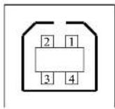
USB series "B" Receptacle Interface
Serial Interface
The RS232 connector on the printer side is a female, DB-9 and pin to pin standard type.
Baud rate: 2400, 4800, 9600(default), 19200, 38400, 57600, 115200
bauds.(programmable by command)
49
OS-2130D & OS-2130DE User's Manual
| Pin | Direction | Definition |
| 1 | Shorted to Pin 4,6 | |
| 2 | Output TX | |
| 3 | Input RX | |
| 4 | Shorted to Pin 1,6 | |
| 5 | Ground | |
| 6 | Shorted to Pin 1,4 | |
| 7 | Input CTS | |
| 8 | Output RTS | |
| 9 | Output +5V |
Note :
- Pin 9 are reserved for KDU (keyboard device unit), therefore do not connect these pins if you are using a general host like a PC.
- OS-2130D, OS-2130DE used with standard RS-232 cable, the user can buy it on local. Argokee attached to the RS-232 cable is a special pin assignment to use in non-OS-2130D, OS-2130DE models.
50
OS-2130D & OS-2130DE User's Manual
Ethernet Interface
The following port complies with Ethernet communication.
| Pin | Signal |
| 1 | Transmit+ |
| 2 | Transmit- |
| 3 | Receive+ |
| 4 | Reserved |
| 5 | Reserved |
| 6 | Receive- |
| 7 | Reserved |
| 8 | Reserved |
51
OS-2130D & OS-2130DE User's Manual
Appendix I-Thermal Print Head Replacement
- Switch off the power and wait for both the LEDs to go off.
- Open the top cover.
- Unlatch the print head module and swing it to the opposite.
- Push the TPH firmly into the mounting bracket to release it from the module.
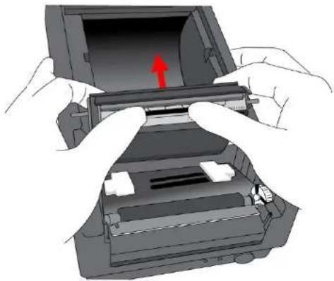
natural_image
Illustration of hands installing or opening a device into a rectangular frame with a red arrow indicating the open portion (no text or symbols present)52
OS-2130D & OS-2130DE User's Manual
- Disassemble the TPH and the metal plate by removing the screws.
- Unplug the 2 print head cables from the connectors on the old TPH-module.
- Replace the TPH.
natural_image
3D mechanical assembly diagram showing internal components with red arrows indicating force or movement (no text or symbols)- Plug the 2 print head cable to the new print head.
- Put the new "Print Head module" onto "Printer Chassis" with the same way, which you released it from "Printer Chassis".
53
OS-2130D & OS-2130DE User's Manual
Appendix II-Cutter Installation
- Turn off the printer power, unplug the power cable and USB/Ethernet/Serial cable.
- Remove the top cover.
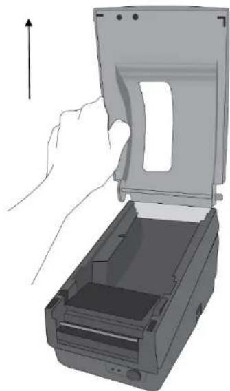
natural_image
Illustration of a hand inserting a device into a printer (no text or symbols visible)Figure 6.1
54
OS-2130D & OS-2130DE User's Manual
- Remove two screws at base housing.
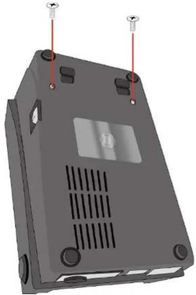
natural_image
3D rendering of a gray electronic device casing with screw holes and ventilation slots (no text or symbols)Figure 6.2
55
OS-2130D & OS-2130DE User's Manual
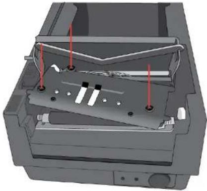
- Remove the whole print head assembly by releasing 4 screws at its feet.
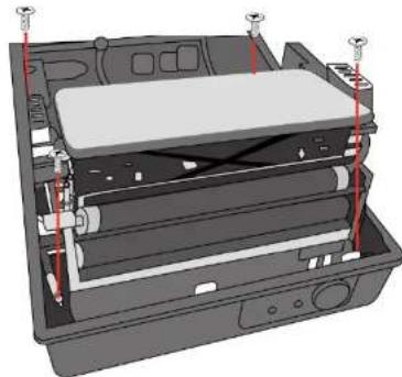
natural_image
3D diagram of a computer chassis with internal components and red indicator lights (no text or symbols)Figure 6.3
- Add a cutter baby board to J5 on the main board.
- Secure three attached screws for the cutter.
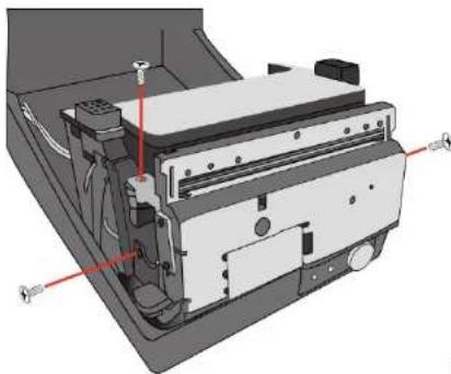
natural_image
3D mechanical assembly diagram showing internal components and mounting points (no text or labels)Figure 6.4
56
OS-2130D & OS-2130DE User's Manual
- Plug the cutter's connector into the PCB's header connector (J3).
- Reinstate the print head assembly by securing back the 4 screws.
- Click back the middle cover.
- Secure two screws back at base housing.
- Install the top cover.
57
OS-2130D & OS-2130DE User's Manual
Appendix III-Dispenser kit Installation
- Turn off the power switch.
- Unwrap the PC bag of dispenser kit to take out the screw, the shaft, the plastic roller, the dispenser bar, the direction label and the peeler sensor cable.
- Take off the top cover of the printer.
- Fix the sensor board on the top cover and secure the screw. Keep the cable at the left.
- Rout the peeler sensor cable through the guides along the left side of the top cover.
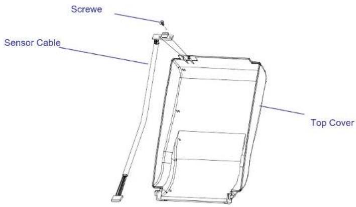
Figure 6.5
58
OS-2130D & OS-2130DE User's Manual
- Release the two screws at the bottom of the base housing shown in Figure 6.1 to 6.3.
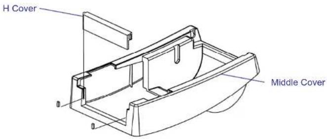
- Remove the middle cover.
- Take off the H cover.
- Tape the direction label on the top of the H cover with the arrow sign heading toward the opposite of you.
- Release the screw on the left bracket of the chassis.
- Unlatch the print head module. Hook the white roller on the brackets of the chassis, ensuring the long thinner end at the left side.
- Guide the shaft and go through the respective holes on the left bracket, the white roller, and the right bracket in order (To smooth this procedure, better hold the white roller with one hand.).
- Secure the attached screw at right bracket of the chassis to fix the shaft.
- Hook the dispenser bar on the brackets of the chassis, positioning it above the white roller. Ensure that the dispenser bar is paralleled with the black platen roller and its long thinner end is
59
OS-2130D & OS-2130DE User's Manual
at that left.
- Plug the sensor board's connector into the PCB's header connector (J2).
- Secure back the screw on the left bracket of the chassis.
- Guide the sensor cable connector through the hole on the upper left corner of the middle cover.
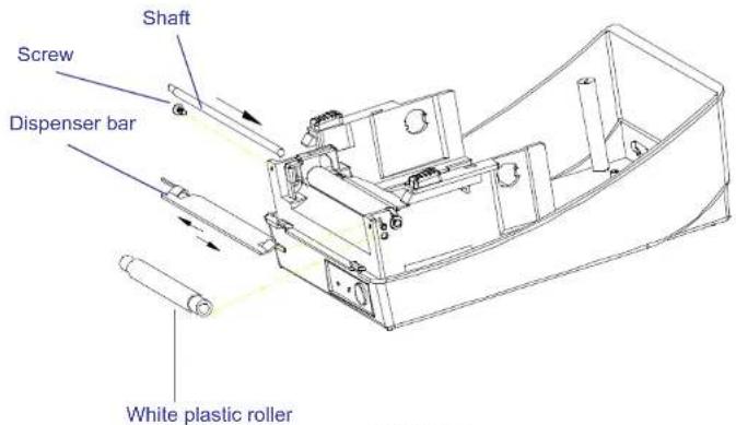
Figure 6.7
60
OS-2130D & OS-2130DE User's Manual
- Click the top cover back to the middle cover.
- Insert the sensor connector into its receptacle on the main logic board of the base housing.
- Click the middle cover back to the base housing. First click in the front part then the rear.
- Secure the two screws at the bottom of the base housing.
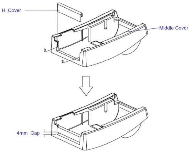
Figure 6.8
61
OS-2130D & OS-2130DE User's Manual