
GD-V4210PCE - Television JVC - Free user manual and instructions
Find the device manual for free GD-V4210PCE JVC in PDF.

| Product Type | 42-inch Professional Plasma Display |
| Model Number | GD-V4210PCE |
| Brand | JVC |
| Display Technology | Plasma |
| Screen Size (Diagonal) | 42 inches |
| Resolution | 1024 x 768 (XGA) |
| Aspect Ratio | 4:3 |
| Brightness | 1000 cd/m² |
| Contrast Ratio | 3000:1 |
| Input Ports | VGA, DVI, S-Video, Composite, Component |
| Dimensions (W x H x D) | 1020 x 580 x 95 mm |
| Weight | Approximately 25 kg |
| Power Consumption (Max) | 320 W |
| Power Supply | AC 100-240V, 50/60Hz |
| Main Features | Professional-grade plasma panel, anti-burn-in technology, RS-232C control, built-in speakers |
| Care and Cleaning | Use dry, soft cloth; avoid liquid cleaners; clean ventilation slots regularly |
| Safety Precautions | Do not block ventilation, avoid extreme temperatures, use grounded outlet |
| Spare Parts and Repairability | Contact authorized JVC service center for replacement parts; power supply and control board available |
| General Information | Designed for commercial signage and presentation use; compatible with standard mounts |
Frequently Asked Questions - GD-V4210PCE JVC
User questions about GD-V4210PCE JVC
0 question about this device. Answer the ones you know or ask your own.
Ask a new question about this device
Download the instructions for your Television in PDF format for free! Find your manual GD-V4210PCE - JVC and take your electronic device back in hand. On this page are published all the documents necessary for the use of your device. GD-V4210PCE by JVC.
USER MANUAL GD-V4210PCE JVC
Thank you for purchasing this JVC Monitor.
Before using the monitor, read this manual carefully so that you know how to use the Monitor correctly.
Refer to this manual whenever questions or problems about operation arise. Be sure to read and observe the safety precautions.
Keep this manual where the user can see it easily.
* Installation and removal require special expertise.
Consult your product dealer for details.
This instruction manual refers to the GD-V4210PZW, GD-V4210PZW-G, GD-V4210PCE, GD-V4210PCE-G, and GD-V4211PCE.
The explanations and illustrations used in this instruction manual are of the GD-V4210PZW unless otherwise stated.
The differences between each model are as follows:
| GD-V4210PZW | GD-V4210PZW-G | GD-V4210PCE | GD-V4210PCE-G | GD-V4211PCE | ||
| Frame Colour | Silver | Gray | Silver | Gray | Silver | |
| Inputs | VIDEO A | Available | Not available*1 | |||
| VIDEO B | Available | Not available*1 | ||||
| COMPONENT | Available | Not available*1 | ||||
*1 These inputs will be available with the separately-purchased video interface kit (IF-C421P1W).
Ask your dealer to install the video interface kit.
Contents
Page
Safety Precautions ......2
Parts Identification....4
- Remote Control ....4
- Monitor: Front View ....5
• Monitor: Rear Views ......6
Preparations 9
- Checking the Accessories ......9
- Installing the Batteries ......9
Installation ....10
- Precautions ....10
Connections ......11
- Precautions ......11
• Available Signals ......11 - Connection Examples ....12
Basic Operations ......14
• Daily Operations....14
- Changing the Aspect Ratio.... 15
Video Adjustments ......16
- Adjusting the Picture Quality 16
- Adjusting the Screen Size and Position...... 17
- Adjusting the Color Temperature 19
- Adjusting the White Balance.... 19
- Changing the Picture Mode...... 21
- Changing the Aspect Ratio.... 21
- Setting the Receivable Signal Types .... 22
- Setting the RGB Input 23
- Resetting the Function Selection Menu Settings .. 23
Page
Other Convenient Functions ......24
• Showing On-screen Display 24
- Confirming the Use Time....25
- Setting the Auto Sleep Function 25
• Prohibiting the Monitor's Button Operations ..... 26
- Showing the On-screen When Changing the Input Mode ....26
- Mounting the Monitor Vertically 27
- Setting the High-Definition signal Types ...... 27
• Using the Pixel Shift Function...... 27
• Using the Power Save Function 28
- Preventing the Afterimage Effect 29
- Refreshing the Screen....29
- Resetting All the Setup Menu Settings ...... 29
- Resetting All the Menu Settings .... 30
Serial Connections and Operations.... 31
- Connecting the Remote Control Cables ...... 31
- Assigning ID Numbers....31
- Operating the Monitors Simultaneously...... 32
- Operating the Monitors Individually .... 32
Menu Classifications ......33
- Main Menu ....33
- Setup Menu ....35
Troubleshooting 36
• Self-diagnostic Indication ....37
Specifications ....38
FCC NOTICE
■ GD-V4210PZW / GD-V4210PZW-G / GD-V4210PCE / GD-V4210PCE-G
CAUTION: Changes or modifications not approved by JVC could void the user's authority to operate the equipment. NOTE: This equipment has been tested and found to comply with the limits for a Class A digital device, pursuant to Part 15 of the FCC Rules. These limits are designed to provide reasonable protection against harmful interference when the equipment is operated in a commercial environment. This equipment generates, uses, and can radiate radio frequency energy and, if not installed and used in accordance with the instruction manual, may cause harmful interference to radio communications. Operation of this equipment in a residential area is likely to cause harmful interference in which case the user will be required to correct the interference at his own expense.
■ GD-V4211PCE
CAUTION: Changes or modifications not approved by JVC could void the user's authority to operate the equipment. NOTE: This equipment has been tested and found to comply with the limits for a Class B digital device, pursuant to Part 15 of the FCC Rules. These limits are designed to provide reasonable protection against harmful interference in a residential installation. This equipment generates, uses and can radiate radio frequency energy and, if not installed and used in accordance with the instructions, may cause harmful interference to radio communications. However, there is no guarantee that interference will not occur in a particular installation. If this equipment does cause harmful interference to radio or television reception, which can be determined by turning the equipment off and on, the user is encouraged to try to correct the interference by one or more of the following measures:
– Reorient or relocate the receiving antenna.
– Increase the separation between the equipment and receiver.
- Connect the equipment into an outlet on a circuit different from that to which the receiver is connected.
- Consult the dealer or an experienced radio/TV technician for help.
EUROPE EMC STANDARD NOTICE
■ GD-V4210PZW / GD-V4210PZW-G / GD-V4210PCE / GD-V4210PCE-G
Warning: This is a class A product. In a domestic environment this product may cause radio interference in which case the user may be required to take adequate measure.
IMPORTANT INFORMATION
WARNING: TO REDUCE THE RISK OF FIRE AND ELECTRIC SHOCK, DO NOT EXPOSE THIS PRODUCT TO RAIN OR MOISTURE.
IMPORTANT SAFEGUARDS
Electrical energy can perform many useful functions. This unit has been engineered and manufactured to assure your personal safety. But IMPROPER USE CAN RESULT IN POTENTIAL ELECTRICAL SHOCK OR FIRE HAZARD. In order not to defeat the safeguards incorporated into this product, observe the following basic rules for its installation, use and service. Please read these “Important Safeguards” carefully before use.
- All the safety and operating instructions should be read before the product is operated.
– The safety and operating instructions should be retained for future reference.
- All warnings on the product and in the operating instructions should be adhered to.
– All operating instructions should be followed.
- Unplug this product from the wall outlet before cleaning. Do not use liquid cleaners or aerosol cleaners. Use a damp cloth for cleaning.
- Do not use attachments not recommended by the product manufacturer as they may be hazardous.
- Do not use this product near water. Do not use immediately after moving from a low temperature to high temperature, as this causes condensation, which may result in fire, electric shock, or other hazards.
- Do not place this product on an unstable cart, stand, or table. The product may fall, causing serious injury to a child or adult, and serious damage to the product. The product should be mounted according to the manufacturer's instructions, and should use a mount recommended by the manufacturer.
- When the product is used on a cart, care should be taken to avoid quick stops, excessive force, and uneven surfaces which may cause the product and cart to overturn, damaging equipment or causing possible injury to the operator.
- Slots and openings in the cabinet are provided for ventilation. These ensure reliable operation of the product and protect it from overheating. These openings must not be blocked or covered. (The openings should never be blocked by placing the product on bed, sofa, rug, or similar surface. It should not be placed in a built-in installation such as a bookcase or rack unless proper ventilation is provided and the manufacturer's instructions have been adhered to.)
For proper ventilation, separate the product from other equipment, which may prevent ventilation and keep distance more than 10 cm ( 3^15/_16 inches).
- This product should be operated only with the type of power source indicated on the label. If you are not sure of the type of power supply to your home, consult your product dealer or local power company.
- This product is equipped with a three-wire plug. This plug will fit only into a grounded power outlet. If you are unable to insert the plug into the outlet, contact your electrician to install the proper outlet. Do not defeat the safety purpose of the grounded plug.
- Power-supply cords should be routed so that they are not likely to be walked on or pinched by items placed upon or against them. Pay particular attention to cords at doors, plugs, receptacles, and the point where they exit from the product.
- For added protection of this product during a lightning storm, or when it is left unattended and unused for long periods of time, unplug it from the wall outlet and disconnect the cable system. This will prevent damage to the product due to lightning and power line surges.
- Do not overload wall outlets, extension cords, or convenience receptacles on other equipment as this can result in a risk of fire or electric shock.
- Never push objects of any kind into this product through openings as they may touch dangerous voltage points or short out parts that could result in a fire or electric shock. Never spill liquid of any kind on the product.
- Do not attempt to service this product yourself as opening or removing covers may expose you to dangerous voltages and other hazards. Refer all service to qualified service personnel.
- Unplug this product from the wall outlet and refer service to qualified service personnel under the following conditions: a) When the power supply cord or plug is damaged.
b) If liquid has been spilled, or objects have fallen on the product.
c) If the product has been exposed to rain or water.
d) If the product operated normally by following the operating instructions. Adjust only those controls that are covered by the Operation Manual, as an improper adjustment of controls may result in damage and will often require extensive work by a qualified technician to restore the product to normal operation.
e) If the product has been dropped or damaged in any way.
f) When the product exhibits a distinct change in performance – this indicates a need for service.
- When replacement parts are required, be sure the service technician has used replacement parts specified by the manufacturer or with same characteristics as the original part. Unauthorized substitutions may result in fire, electric shock, or other hazards.
- Upon completion of any service or repairs to this product, ask the service technician to perform safety checks to determine that the product is in proper operating condition.
- The product should be placed more than 30~cm ( 11^15 / _16 inches) away from heat sources such as radiators, heat registers, stoves, and other products (including amplifiers) that produce heat.
- When connecting other products such as VCR's, and personal computers, you should turn off the power of this product for protection against electric shock.
- Do not place combustibles behind the cooling fan. For example, cloth, paper, matches, aerosol cans or gas lighters that present special hazards when over heated.
- Use only the accessory cord designed for this product to prevent shock.

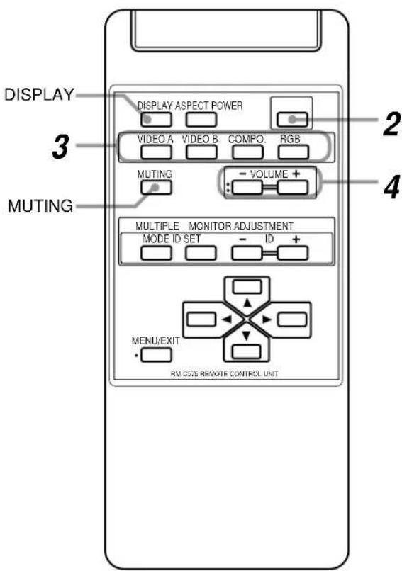
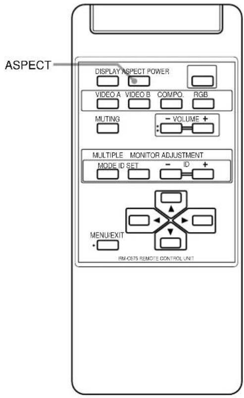
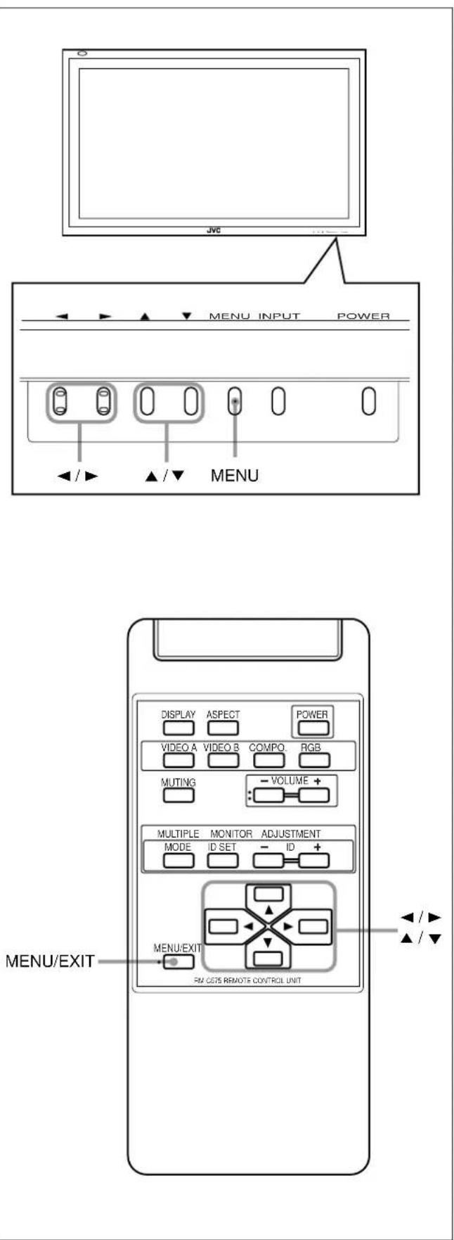
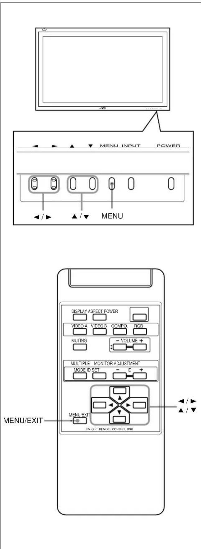
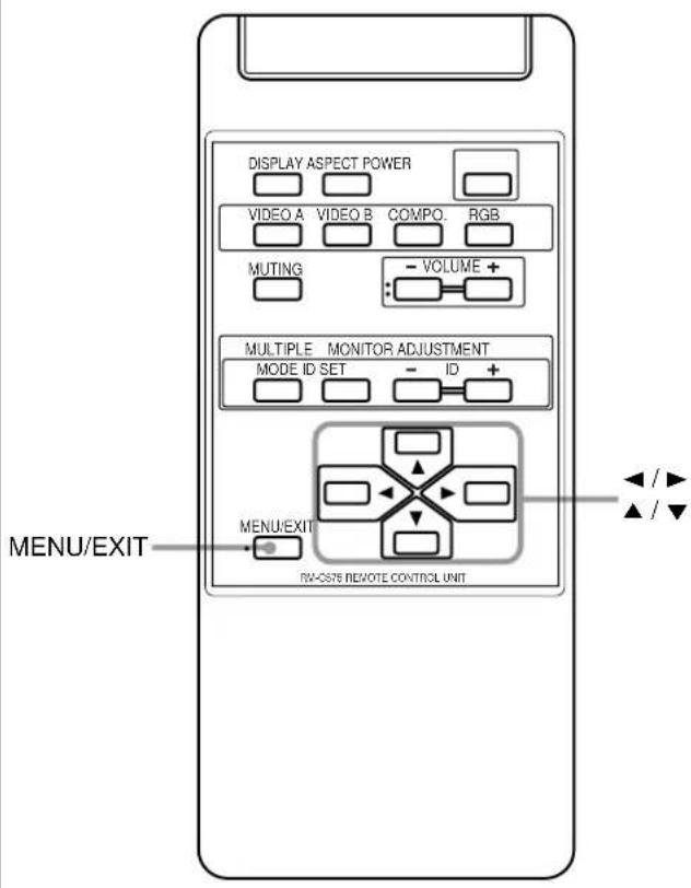
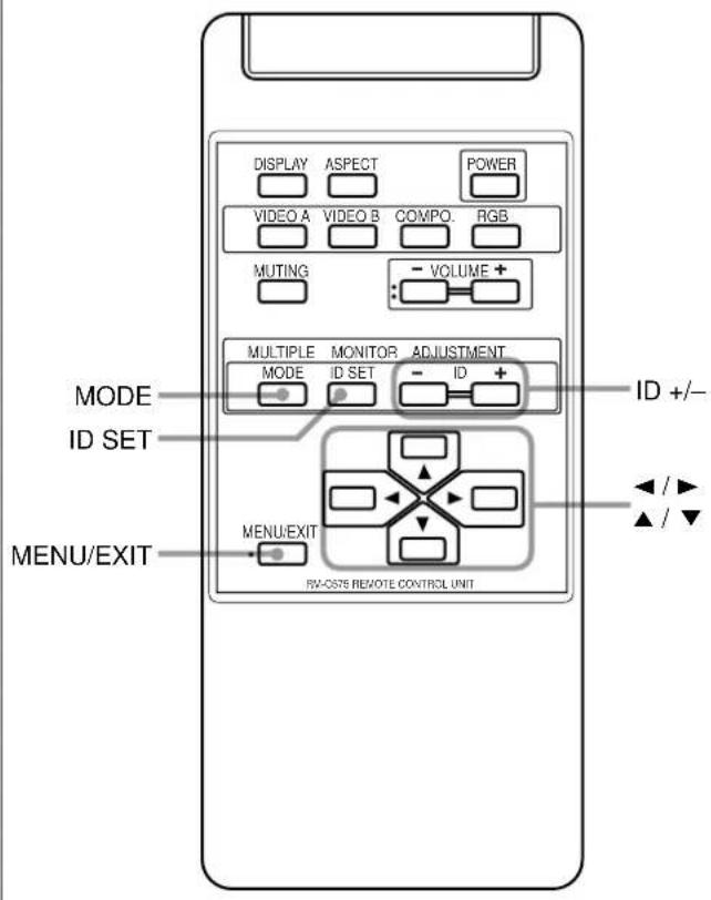
Remote Control
1 Remote signal transmission window
2 DISPLAY button (page 14)
Use this button to display the input terminal, color system (for VIDEO A or B input), scan system (for COMPONENT input) and horizontal/vertical frequency (for RGB input).
Pressing the button again will make the display disappear.
3VIDEO A, VIDEO B, COMPO. and RGB buttons (page 14)
Use these buttons to switch between inputs. To select the correct RGB input, you have to set "RGB INPUT" correctly on the menu (see page 23).
- Only for GD-V4210PCE, GD-V4210PCE-G and GD-V4211PCE: Only RGB input can be reproduced. To reproduce images through the other inputs, you need to install video interface kit (IF-C421P1W), which is separately purchased.
4 MUTING button (page 14)
Use this button to turn off the volume immediately. Pressing the button again will resume the previous volume level.
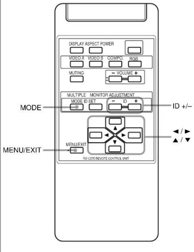
5 MULTIPLE MONITOR ADJUSTMENT buttons (page 31)
Use these buttons to set IDs, etc. when serial connection is made.
6 MENU/EXIT button
Use this button to display or erase menus. While a sub-menu is displayed, pressing this button will move you one screen back to the preceding menu.
7 Remote control cable jack (page 31)
Connect the remote control cable when using this remote control as a wired remote control.
8 ASPECT button (page 15)
Use this button to switch between aspect ratios. Each time you press the button, the aspect ratio changes as follows:

9 POWER button (page 14)
Use this button to turn on/off the power.
10 VOLUME + / - buttons (page 14)
Use these buttons to adjust the volume level.
11 ▲ / ▶ / ▲ / ▼ buttons
Use these buttons to select menu items or make adjustments.
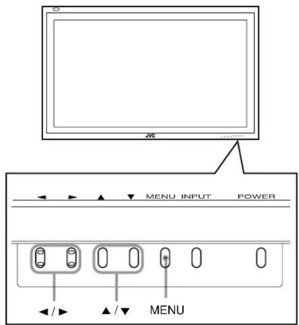
Monitor: Front View
1 Remote sensor/power lamp
Point the front end of the wireless remote control toward here.
When the Monitor is turned on, the power lamp glows green. It glows orange in standby mode.
2 Self-diagnostic lamps (page 37)
These lamps light/flash if something abnormal occurs with the Monitor.
3 ◀/▶/▲/▼ buttons
Use these buttons to select menu items and to make adjustments.
- When no menu is displayed, you can use the ◀ / ▶ buttons to adjust the volume level.
4 MENU button
Use this button to display or erase menus. While a sub-menu is displayed, pressing this button will move you one screen back to the preceding menu.
5 INPUT button (page 14)
Use this button to switch between inputs. To select the correct RGB input, you have to set "RGB INPUT" correctly on the menu (see page 23).
- Only for GD-V4210PCE, GD-V4210PCE-G and GD-V4211PCE: Only RGB input can be reproduced. To reproduce images through the other inputs, you need to install video interface kit (IF-C421P1W), which is separately purchased.
6 POWER button (page 14)
Use this button to turn on and off the Monitor.
Monitor: Rear Views
1 AUDIO output terminal (pin jack) (page 12)
Connect these terminals to the audio input terminals of external equipment such as an amplifier.
2 REMOTE 1 (RS232C) terminal (D-sub, 9-pin) (page 12)
Connect this terminal to the RS-232C terminal of a personal computer.
- For the control method using this terminal, consult an authorized JVC dealer.
3 AC INPUT terminal (page 12)
Connect the supplied power cord to this terminal.
4 MAIN POWER switch (page 14)
Setting this switch to ON will put the Monitor into standby mode, allowing you to turn on and off the power using the POWER button either on the remote control or on the Monitor.
5 SPEAKER OUT terminals (page 12)
Connect external speakers.
6 INTERNAL/EXTERNAL (built-in speaker/external speaker) selecting switch (page 12)
INTERNAL: To use built-in speakers. EXTERNAL: To use external speakers.
7 REMOTE 2 (JVC CODE) terminals (mini jack) (page 31)
• IN
For Master Monitor: Connect a wired remote control to this terminal for serial connection.
For Slave Monitors: Connect to the REMOTE 2 OUT terminal of another Monitor in serial connection.
• OUT
Connect to the REMOTE 2 IN terminal of another Monitor for serial connection.
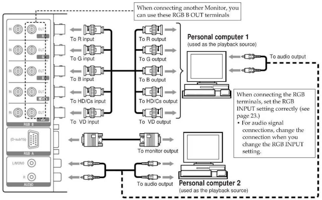
8 RGB B input/output terminals (page 12)
• R, G, B, HD/Cs, VD input terminals (BNC)
Connect these terminals to the following output terminals of a personal computer or other equipment:
- Analog RGB signal output terminals
- Horizontal sync (HD) signal or composite (Cs) signal output terminal
- Vertical sync (VD) signal output terminal
Notes:
- External sync signals are automatically detected when they come in.
- When both horizontal (HD)/vertical (VD) sync and composite (Cs) sync are connected, HD/VD sync signals will be used.
• R, G, B, HD/Cs, VD output terminals (BNC)
Connect these terminals to the following input terminals of another monitor:
- Analog RGB signal input terminals
- Horizontal sync (HD) signal or composite (Cs) signal input terminal
- Vertical sync (VD) signal input terminal
9RGB A input terminal (D-sub, 15-pin) (page 12)
Connect this terminal to the video output terminal of a personal computer.
10 AUDIO input terminals (pin jack)
Connect these terminals to the audio output terminals of a personal computer or other equipment which is also connected to the RGB A or RGB B input terminals.
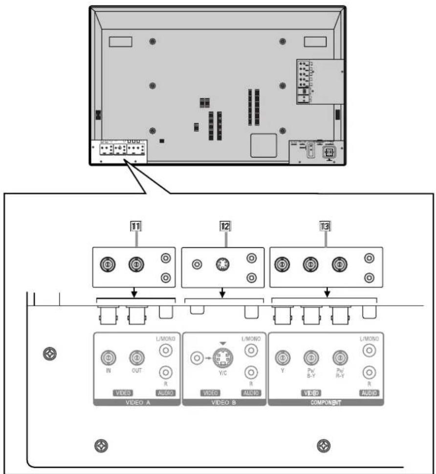
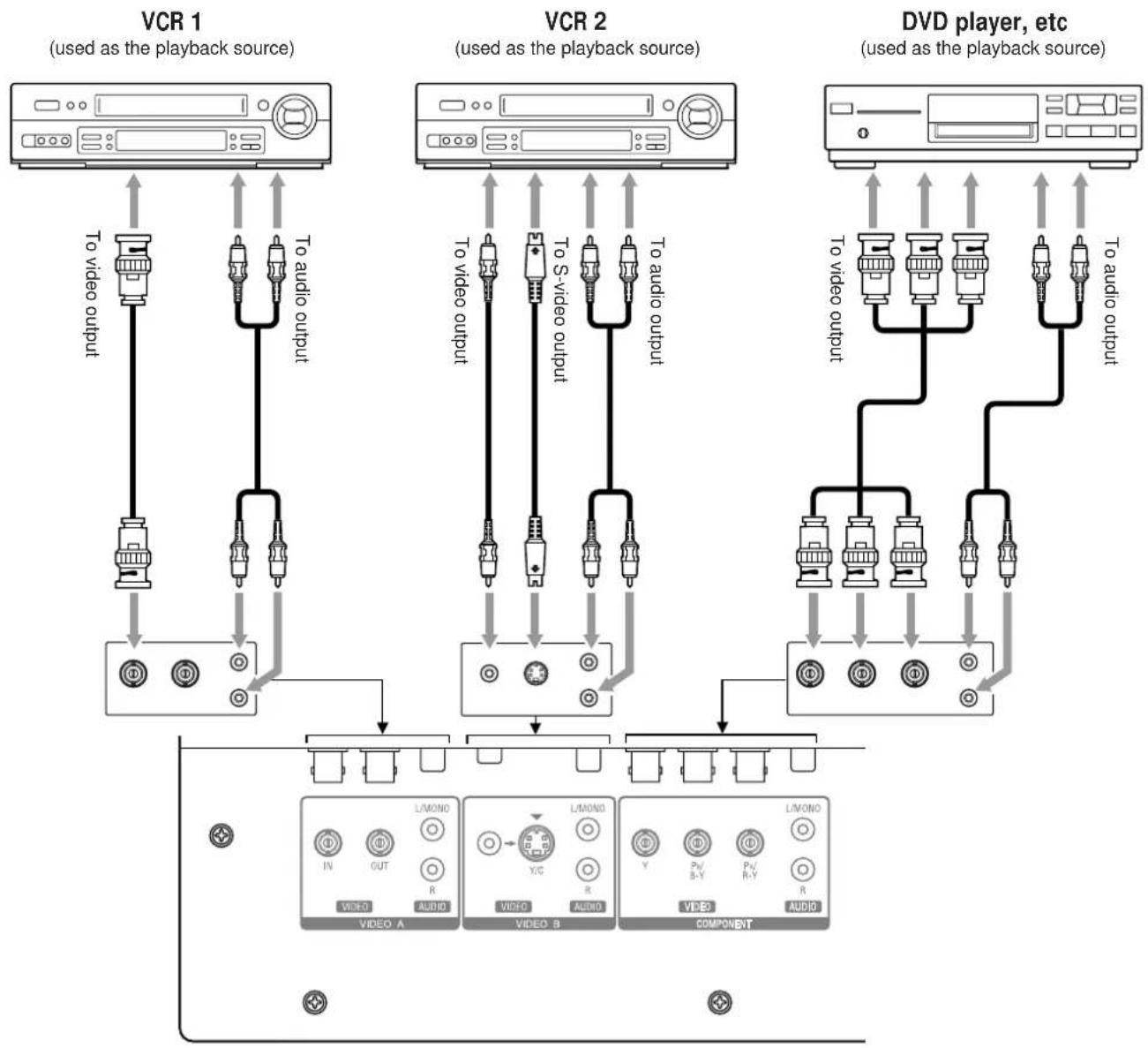
11VIDEO A terminals (page 13)\*
• Video input terminal (BNC)
Connect this terminal to the video output terminal of a VCR, etc.
• Video output terminal (BNC)
Connect this terminal to the video input terminal of another Monitor.
- Audio input terminals (pin jack)
Connect these terminals to the audio input terminals of a VCR, etc.
Note:
- Since the video output terminal on this Monitor is loop-though terminals, the devices connected to this video output terminal should be correctly terminated. Otherwise, pictures become abnormally bright.
12VIDEO B terminals (page 13)\*
- Y/C (S video) input terminal (Y/C terminal)
Connect this terminal to the S-video output terminal of a VCR, etc.
• Video input terminal (pin jack) Connect this terminal to the video output terminal of a VCR, etc. - Audio input terminals (pin jack) Connect these terminals to the audio output terminals of a VCR, etc.
Note:
- When both the video and S-video terminals are connected, the S-video terminal will have priority.
13COMPONENT input terminals (page 13)\*
- Y, P_B/B-Y, P_B/R-Y input terminals (BNC) Connect these terminals to the component signal output terminals of NTSC or high-vision equipment.
- Audio input terminals (pin jack) Connect these terminals to the audio output terminals of the other equipment.
Note:
* GD-V4210PCE, GD-V4210PCE-G, and GD-V4211PCE do not have the following input terminals – VIDEO A, VIDEO B, and COMPONENT. To input video, S-video, and component signals, you need to install video interface kit (IF-C421P1W), which is separately purchased.
Checking the Accessories
The following accessories are included with the Monitor. Check for them. If any item is missing, please contact the dealer where you purchased the Monitor.
• Remote control (RM-C575) x 1
- Remote control cable x 1
• Power cord x 3 (Use the one matching the wall outlet.)
- Batteries (AA/R6P) x 2
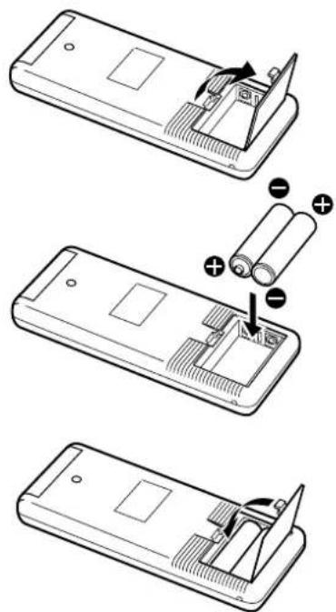
Installing the Batteries
Put the batteries in the remote control as follows. If the remote control has become erratic in operation, change the batteries.
1 Remove the back cover.
While pushing the release lever on the cover, remove the cover in the direction of the arrow.
2 Place the batteries.
Put the two supplied batteries (AA/R6P), noting the ⊕ and ⊖ markings, as shown.
3 Replace the back cover as illustrated.
Make sure the release lever on the cover is locked in place correctly.
Precautions for using batteries
If batteries are used improperly, the liquid could leak out, causing a fire, injury, etc. or dirtying the vicinity. Take notice of the following:
- Do not mix old and new batteries.
- Do not mix different types of battery as different types may have different characteristics.
- Place the batteries according to the and markings indicated on the battery compartment.
- When installing the batteries, insert the end first to avoid a short circuit.
- Use only the specified batteries.
- When you are not using the remote control for a long time, remove the batteries.
- Do not throw the batteries into fire or try recharging them.
- When the batteries have reached the end of their life, replace them with new ones immediately. Otherwise, the liquid may leak out, or malfunction may be caused by the leaked liquid. If the leaked liquid contacts your skin, wipe off the liquid with a soft cloth. If the affected skin is left as is, you may get a rough skin.
- The service life of batteries is six months to one year for normal use. The supplied batteries are only for checking the operation and their life may be shorter. When the remote control operation becomes erratic, replace with new batteries.
The instruction below applies only to the use in Holland.
- When mounting the Monitor vertically, it is necessary to adjust the cooling fan speed to provide better heat dissipation. Do not forget to perform this adjustment. (See page 27.)
- When installing the Monitor, be sure to use a dedicated Stand Unit, Wall Mounting Unit, or Monitor Hanger Unit, depending on a particular case. Ask your dealer for installation.
- When installing the Monitor, refer also to the user manual for each option to use. Do not tilt the Monitor rightward, leftward, or backward.
- Route the power cord and connection cables along wall or floor corners to avoid walking on them.
- For good heat dissipation, try to leave the following distances of space (minimum) around the Monitor.
- The ambient temperature of the installation place should be within the range of 0^ to 40^ .
- When installing the Monitor in a place, such as near the ceiling, the remote control may not work correctly because of possible effects from the surroundings. If this happens, use the remote control as a wired remote control or move the Monitor where it is free from these effects.
When installing the Monitor on a stand
Front View
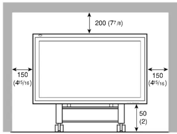
Side View
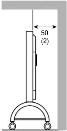
Unit: mm (inch)
Take measures against the Monitor from overturning:
To protect against abnormal events such as earthquakes and to prevent unexpected accidents, take appropriate measures for preventing the Monitor from overturning; should it overturn, this could lead to personal injury.
For detailed information, refer to the manual supplied for the stand.
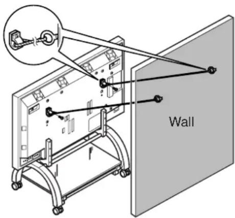
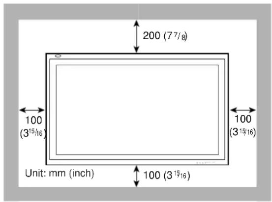
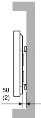
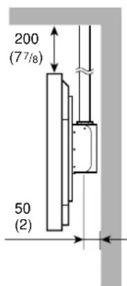
When mounting the Monitor on the wall
Front View
Side View
When hanging the Monitor from the ceiling
Side View
Unit: mm (inch)
Notes:
- Do not allow the same image (pattern) to be continuously displayed on the screen for a long time; otherwise, the area on the screen corresponding to the image may vary in brightness, leaving an afterimage on the screen. To reduce the afterimage, you can use the Refresh function (see page 29).
- The Monitor is manufactured using very high-precision technology, allowing for more than 99.99% active pixels, however, be aware that only a slight number of pixels may be deficient or lit at all times.
- Do not install the Monitor in such a way that the Monitor and other AV equipment affect each other adversely. (For example, if a disturbed image or noise due to electromagnetic interference occurs, or if the infrared remote control malfunctions, change the installation place.)
Precautions
- Before making connections, turn off all the equipment.
- Plugs should be firmly inserted; poor connection could cause noise.
- To unplug a cord, be sure to grasp its plug and pull it out.
- Connect the power cord after having finished all other connections.
- Refer also to the user manual of each piece of equipment.
Available Signals
Video signals
The following signals can be input to this Monitor:
• VIDEO A and VIDEO B terminals accept — PAL, NTSC, NTSC4.43, and SECAM signals.
- COMPONENT terminals accept — 480i, 576i, 480p, 720p, and 1080i (1035i) signals.
(For GD-V4210PCE, GD-V4210PCE-G, and GD-V4211PCE, to input the above signals, you need to install the video interface kit (IF-C421P1W), which is separately purchased.)
Computer signals (Preset and user-defined video modes)
This Monitor has 13 preset video modes for the most popular industrial standard (marked with ● in the table below), and the signals of the following image resolutions can be input to the RGB input terminals.
For less common video modes, this Monitor can also display a picture, and memorize the video modes as user-defined video modes (up to five modes).
When a signal other than any of the preset modes is input, it will automatically be stored as a user-defined video mode, and when a sixth user-defined video signal is input, the first mode will be erased from memory.
| No. | Signal name | Screen resolution | Horizontal Frequency (kHz) | Vertical Frequency (Hz) | Scan system | Preset setting | |
| Horizontal | Vertical | ||||||
| 1 PC98 | 640 400 24.8 56.4 | Non-interlace ● | |||||
| 2 VGA | A400-70 640 400 31.5 | 70.1 Non-interlace ● | |||||
| 3 VGA | A480-60 640 480 31.5 | 59.9 Non-interlace ● | |||||
| 4 VGA | A480-72 640 480 37.9 | 72.8 Non-interlace ● | |||||
| 5 VGA | A480-75 640 480 37.5 | 75.0 Non-interlace ● | |||||
| 6 MAC13" | 640 480 35.0 | 66.7 Non-interlace ● | |||||
| 7 SVGA | -56 800 600 35.2 | 56.3 Non-interlace ● | |||||
| 8 SVGA | -60 800 600 37.9 | 60.3 Non-interlace ● | |||||
| 9 SVGA | -72 800 600 48.1 | 72.2 Non-interlace ● | |||||
| 10 XGA | -60 1024 768 48.4 | 60.0 Non-interlace ● | |||||
| 11 XGA | -70 1024 768 56.5 | 70.1 Non-interlace ● | |||||
| 12 RGB15K | - | — | 15.7 59.9 Interlace ● | ||||
| 13 RGB15K | - | — | 15.6 50.0 Interlace ● | ||||
| - | User-defined | — | — | 15.0 – 16.0 | 50.0 – 75.0 | Interlace | |
| - | User-defined | — | — | 16.0 – 56.0 | 50.0 – 75.0 | Non-interlace | |
Notes:
- When you are viewing XGA, setting the refresh rate (vertical scan frequency) of your personal computer to 60 Hz will enhance the video image.
- When a signal other than listed above is input, a part of the screen may become void or an unnecessary picture may appear.
- Signals, though they are within the acceptable range of frequencies, may not be displayed normally, depending on the signal type.
- Depending on the connected equipment, the Monitor may not be compatible with composite sync (Cs) or G on sync signals.
- When a preset mode signal is input, the vertical frequency displayed on the screen will have an “*” shown at its right top position.
- When No. 7 to No. 11 signals are input, thin lines may happen to be hard to view on the screen, due to the internal digital processing.
Connection Examples
RGB connections
flowchart
graph TD
    A["RGB B"] -->|To R input| B["Personal computer 1 (used as the playback source)"]
    A -->|To G input| B
    A -->|To B input| B
    A -->|To HD/Cs input| B
    A -->|To VD input| B
    B -->|To R output| C["Personal computer 2 (used as the playback source)"]
    B -->|To G output| C
    B -->|To B output| C
    B -->|To HD/Cs output| C
    B -->|To VD output| C
    C -->|To audio output| D["Computer"]
    D -->|To audio output| E["Personal computer 1"]
    E -->|To monitor output| F["Personal computer 2"]
    F -->|To audio output| E
    style A fill:#f9f,stroke:#333
    style B fill:#ccf,stroke:#333
    style C fill:#cfc,stroke:#333
    style D fill:#fcc,stroke:#333
    style E fill:#cff,stroke:#333
System connections
flowchart
graph TD
    A["Amplifier, etc."] -->|To audio input| B["Remote control"]
    B --> C["Remote control cable (supplied)"]
    C --> D["Remote 1 (RS232C)"]
    C --> E["Remote 2 (JVC CODE)"]
    D --> F["AC INPUT (120/230V)"]
    E --> G["MAIN POWER"]
    F --> H["Power cord (supplied)"]
    G --> I["External speakers"]
    H --> J["To a wall outlet"]
    I --> K["External speakers, set this to EXTERNAL."]
    L["Personal computer (used to control the Monitor)"] --> M["To RS-232C"]
    M --> N["Computer"]
AV connections
These terminals are not available for GD-V4210PCE, GD-V4210PCE-G, and GD-V4211PCE. To use them, you need to install video interface kit (IF-C421P1W), which is separately purchased.
flowchart
graph TD
    subgraph_VCR_1["Used as the playback source"]
        A1["To video output"] --> B1["Audio Module"]
        A2["To audio output"] --> B2["Audio Module"]
        A3["To video output"] --> B3["Video Module"]
        A4["To video output"] --> B4["Video Module"]
        A5["To audio output"] --> B5["Audio Module"]
    end

    subgraph_VCR_2["Used as the playback source"]
        C1["To video output"] --> D1["Audio Module"]
        C2["To S-video output"] --> D2["Video Module"]
        C3["To audio output"] --> D3["Video Module"]
        C4["To video output"] --> D4["Video Module"]
        C5["To audio output"] --> D5["Video Module"]
    end

    subgraph DVD Player_DVD
        E1["To video output"] --> F1["LIMONO Audio Module"]
        E2["To video output"] --> F2["LIMONO Audio Module"]
        E3["To audio output"] --> F3["LIMONO Audio Module"]
        E4["To video output"] --> F4["LIMONO Audio Module"]
        E5["To audio output"] --> F5["LIMONO Audio Module"]
        E6["To video output"] --> F6["LIMONO Audio Module"]
        E7["To video output"] --> F7["LIMONO Audio Module"]
        E8["To audio output"] --> F8["LIMONO Audio Module"]
    end

    VCR_1 --> VCR_2
    VCR_2 --> DVD Player_DVD
    VCR_1 --> VCR_2
    VCR_2 --> DVD Player_DVD
    VCR_1 --> VCR_1
    VCR_2 --> VCR_2
    VCR_1 --> VCR_1
    VCR_2 --> VCR_2
    VCR_1 --> VCR_1
    VCR_2 --> VCR_2
Notes:
- You can connect another VCR or Monitor to the VIDEO A OUT terminal. However, when connecting a VCR to the VIDEO A terminals, do not connect both IN and OUT terminals to the same VCR.
- When connecting a VCR to the VIDEO B terminals, you can use either the video or S-video terminals. If the both terminals are used, S-video terminal will have priority.
Rear View
Daily Operations
1 Turn on the main power.
Set MAIN POWER on the back of the Monitor to ON. The POWER lamp on the upper left of the front panel glows orange.
2 Turn on the power.
Press POWER on the remote control to turn the power on. The POWER lamp changes to glow green.
- You can also use the POWER on the front panel (lower right) to turn on the Monitor.
3 Select an input.
Select the desired input by pressing VIDEO A, VIDEO B, COMPO. or RGB.
- You can also select the input by pressing INPUT on the Monitor. Each time you press the button, the input mode changes in sequence.
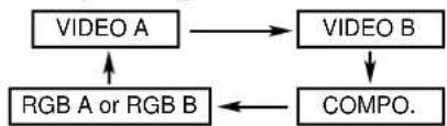
flowchart
graph TD
    A["VIDEO A"] --> B["VIDEO B"]
    C["RGB A or RGB B"] --> A
    D["COMPO."] --> C
- Only for GD-V4210PCE, GD-V4210PCE-G, and GD-V4211PCE: You can only select RGB.*
flowchart
graph TD
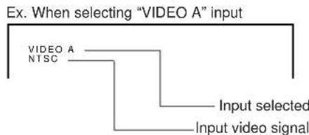
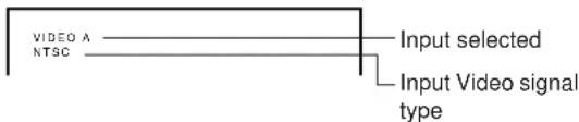
A["EX. When selecting "VIDEO A" input"] --> B["VIDEO A NTSC"]
B --> C["Input selected"]
C --> D["Input video signal"]
Note:
- This Monitor has two RGB input terminals — RGB A and RGB B. When you select the RGB input, the one set on the menu (RGB INPUT: see page 23) is selected as the input source. If you want to select the other RGB input than the current one, change the RGB INPUT setting on the menu.
4 Adjust the volume.
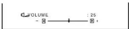
Notes:
- While no menu is displayed, you can adjust the volume by pressing ◀ / ▶ on the Monitor.
- When the INTERNAL/EXTERNAL selecting switch on the back of the Monitor is set to EXTERNAL, no sounds come out of the built-in speakers.
When you want to hear audio sound from the built-in speakers, set the INTERNAL/EXTERNAL selecting switch to INTERNAL.
To turn off the volume immediately
Press MUTING.
"MUTING ON" is displayed, and the sound goes out.
Pressing the button again resumes the previous volume level.
To make the screen indication appear
Press DISPLAY.
The types of input and signal are indicated on the screen for about 3 seconds.
You can also make the screen indication appear using menus (page 24).
Changing the Aspect Ratio
Precautions for using the screen mode switching function
- This Monitor features a screen mode switching (aspect ratio change) function. If you select a mode different in aspect ratio from software such as TV programs, the picture may look different from original picture. Be aware of this point when you are selecting a screen mode.
- If you select a wide screen mode while viewing conventional video programs of the aspect ratio 4:3, some portions (edges) of the original picture will be cut off, or deformed. To enjoy the original picture as it is, select "REGULAR" while viewing such programs.
- If you place the Monitor in a tea room, hotel, etc. for business purposes or public viewing and modify the picture by using the screen mode switching (aspect ratio change) function, this could violate the copyright protected by the copyright law, which requires your special attention.
- If you make the screen very bright and watch programs selecting "REGULAR" for a long period of time, the Monitor screen may happen to be burned in. If this occurs, watching programs using a wide screen mode for a while will reduce the burn-in gradually.
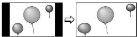
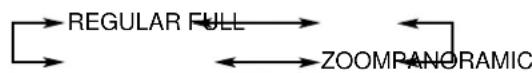
With this Monitor, you can select among three types of wide screens (FULL, ZOOM, and PANORAMIC) in addition to the REGULAR screen of conventional 4:3 aspect ratio.
Press ASPECT to select the screen size
Each time you press the button, the screen size changes as follows:

REGULAR: Displays at conventional 4:3 aspect ratio.

FULL: REGULAR size display is enlarged horizontally.

natural_image
Two grayscale images showing balloons floating in a 3D space, one with a flag-like element and the other with a flag-like element (no text or symbols)ZOOM: REGULAR size display is enlarged vertically and horizontally at the same ratio.

natural_image
Two grayscale images showing balloons above and below a frame, with no text or symbols present.PANORAMIC: REGULAR size display is enlarged horizontally to the extent that the picture does not look abnormally.
natural_image
Diagram showing two stages of balloons shifting from left to right, with no text or symbols present.Notes:
- When one of the following signals is being input, you cannot select the aspect ratio you want.
■ 1080i, 1035i or 720p signal through the COMPONENT input terminals You can only select FULL.
■ 480p signal through the COMPONENT input terminals You cannot select PANORAMIC.
■ When any signal other than RGB15K-60 and RGB15K-50 through the RGB input terminals You can select only REGULAR and FULL. - The aspect ratio can also be changed on the Function Selection Menu (page 21).
For video adjustments, use menus.
You can use the buttons either on the remote control or on Monitor for menu operations.
- Refer also to "Menu Classifications" on pages 33 and 35.
Adjusting the Picture Quality
Picture quality can be set for each input mode.
1 Press MENU/EXIT (or MENU on the Monitor) to display the Main Menu.
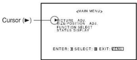
2 Press ▲/▼ to move the cursor (▶) to "PICTURE ADJ."
3 Press ▶ to display the Picture Adjustment Menu.
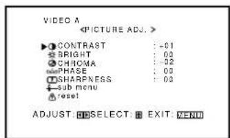
4 Press ▲/▼ to move the cursor (▶) to the item you want to adjust.
Item Adjustment Standard range (Reset)
CONTRAST -20 to +20 +10
BRIGHT (brightness) -20 to +20 0
CHROMA* -20 to +20 0
PHASE^**-20 to+20 0
SHARPNESS -20 to +20 0
sub menu See "To make an adjustment while viewing the adjustment bar" on the next page.
reset See "To reset the adjustments" on the next page.
* Adjustment is not possible when RGB input is selected. **Adjustment is only possible when viewing NTSC signal through the VIDEO A or B terminal.
5 Press ◀/▶ to make adjustments.
6 Press MENU/EXIT (or MENU on the Monitor) twice to exit from the menu operations.
To make an adjustment while viewing the adjustment bar
After step 3 on page 16, proceed as follows:
1 Press ▲/▼ to move the cursor (▶) to "sub menu."
2 Press ▶ to display the Sub Menu.
The Sub Menu for CONTRAST appears on the screen.
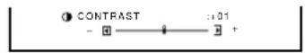
3 Press ▲/▼ to select the Sub Menu you want to adjust. Each time you press the button, the Sub Menu changes as follows:
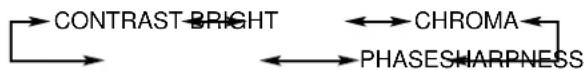
flowchart
graph LR
    A["CONTRAST-BRIGHT"] --> B["PHASESHARPNESS"]
    B --> C["CHROMA"]
    C --> A
4 Press ◀/▶ to adjust the selected item.
5 Repeat steps 3 and 4 to adjust the other items.
6 Press MENU/EXIT (or MENU on the Monitor) three times to exit from the menu operations.
To reset the adjustments
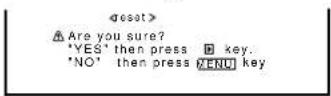
After step 3 on page 16, proceed as follows:
1 Press ▲/▼ to move the cursor (▶) to "reset."
2 Press ▶.
The confirmation screen appears.
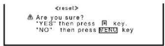
3 Press ▶ again to reset the adjustments.
To cancel the reset, press MENU/EXIT (or MENU on the Monitor).
Adjusting the Screen Size and Position
The screen size and position can be adjusted.
Adjusted settings can be stored for each signal type; therefore, when the same signal comes in, the stored settings are recalled.
- When adjusting the size, the size cannot be adjusted proportionally, but can be enlarged rightward (or downward) only and reduced leftward (or upward) only. Therefore, it is necessary to adjust both the size and position alternately to adjust to the appropriate size.
1 Press MENU/EXIT (or MENU on the Monitor) to display the Main Menu.
2 Press ▲/▼ to move the cursor (▶) to "SIZE/POSITION ADJ."
3 Press ▶ to display the Size/Position Adjustment Menu.
4 Press ▲/▼ to move the cursor (▶) to the item you want to adjust.
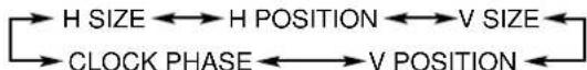
| Item Adjustment range | |
| H (horizontal) SIZE -80 to +80 | |
| H POSITION -80 to +80 | |
| V (vertical) SIZE -80 to +80 | |
| V POSITION -80 to +80 | |
| CLOCK PHASE* -20 to +20 | |
| sub menu See “To make an adjustment while viewing the adjustment bar” on the next page. | |
| reset See “To reset the adjustments” on the next page. | |
* CLOCK PHASE can be used, while RGB input is selected, to reduce flickering and blurring on the screen after adjusting the screen size.
(To be continued on the next page)

5 Press ◀/▶ to adjust the selected item.
6 Press MENU/EXIT (or MENU on the Monitor) twice to exit from the menu operations.
To make an adjustment while viewing the adjustment bar
After step 3 on page 17, proceed as follows:
1 Press ▲/▼ to move the cursor (▶) to "sub menu."
2 Press ▶ to display the Sub Menu.
The Sub Menu for H SIZE appears on the screen.
3 Press ▲/▼ to select the Sub Menu you want to adjust.
Each time you press the button, the Sub Menu changes as follows:
4 Press ◀/▶ to adjust the selected item.
5 Repeat steps 3 and 4 to adjust the other items.
6 Press MENU/EXIT (or MENU on the Monitor) three times to exit from the menu operations.
To reset the adjustments
After step 3 on page 17, proceed as follows:
1 Press ▲/▼ to move the cursor (▶) to "reset."
2 Press ▶.
The confirmation screen appears.
3 Press ▶ again to reset the adjustments.
To cancel the reset, press MENU/EXIT (or MENU on the Monitor).
Note:
- Adjustment values for both horizontal and vertical sizes of the screen are so related that if one is adjusted up to near the maximum value, the attainable value of the other will be decreased.
Adjusting the Color Temperature
The adjusted setting applies to all inputs.
1 Press MENU/EXIT (or MENU on the Monitor) to display the Main Menu.

2 Press ▲/▼ to move the cursor (▶) to "FUNCTION SELECT."
3 Press ▶ to display the Function Selection Menu.
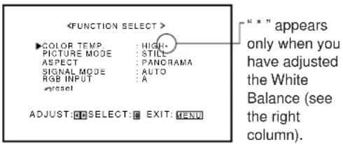
4 Press ▲/▼ to move the cursor (▶) to "COLOR TEMP."
5 Press ◀/▶ to make an adjustment.
Each time you press the button, the color temperature alternates between "HIGH" and "LOW."
HIGH: To make the screen become bluish.
LOW: To make the screen become reddish.
6 Press MENU/EXIT (or MENU on the Monitor) twice to exit from the menu operations.
Note:
- To make a fine adjustment, adjust "WHITE BALANCE" (see the right column).
Adjusting the White Balance
G GAIN, B GAIN and R GAIN can be finely adjusted separately for "HIGH" and "LOW" settings of the color temperature.
When using plural numbers of the Monitors, this can be useful to have the same color on each screen.
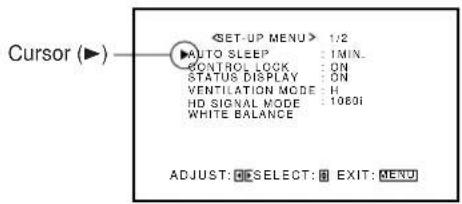
1 On the remote control: Press MENU/EXIT while holding VOLUME – to display the Setup Menu.
On the Monitor: Press MENU while holding ◀ to display the Setup Menu.
2 Press ▲/▼ to move the cursor (▶) to "WHITE BALANCE."
- The Setup Menu consists of two pages. If you keep pressing ▲/▼, you can move to the other page from the current page.
3 Press ▶ to display the White Balance Adjustment Menu.
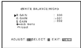
4 Press ▲/▼ to move the cursor (▶) to the item you want to adjust.
5 Press ◀/▶ to adjust the selected item.
6 Repeat steps 4 and 5 to adjust the other items.
7 Press MENU/EXIT (or MENU on the Monitor) twice to exit from the menu operations.
Notes:
- Adjustable range will vary among the Monitors.
- "MAX" may appear soon after you begin adjustment. This is normal but not a malfunction.
To make an adjustment while viewing the adjustment bars
After step 3 on page 19, proceed as follows:
1 Press ▲/▼ to move the cursor (▶) to "sub menu."
2 Press ▶ to display the Sub Menu.
The Sub Menu for R GAIN appears on the screen.

3 Press ▲/▼ to select the Sub Menu you want to adjust. Each time you press the button, the Sub Menu changes as follows:
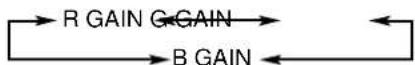
4 Press ◀/▶ to adjust the selected item.
5 Repeat steps 3 and 4 to adjust the other items.
6 Press MENU/EXIT (or MENU on the Monitor) three times to exit from the menu operations.
To reset the adjustments
After step 3 on page 19, proceed as follows:
1 Press ▲/▼ to move the cursor (▶) to "reset."
2 Press ▶.
The confirmation screen appears.
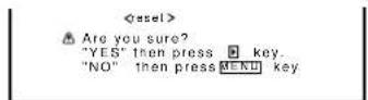
3 Press ▶ again to reset the adjustments.
To cancel the reset, press MENU/EXIT (or MENU on the Monitor).
Changing the Picture Mode
When one of the following signals comes in through the RGB terminals — RGB15K-50, RGB15K-60, PC98, VGA480-60, SVGA-56, SVGA-60, and XGA-60, you can select the picture mode suited to either still pictures or moving pictures.
1 Press MENU/EXIT (or MENU on the Monitor) to display the Main Menu.
2 Press ▲/▼ to move the cursor (▶) to "FUNCTION SELECT."
3 Press ▶ to display the Function Selection Menu.
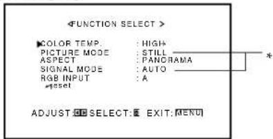
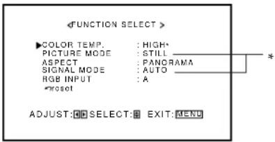
* "PICTURE MODE" and "SIGNAL MODE" do not appear at the same time.
"PICTURE MODE" appears when RGB input is selected, and one of the following signals comes in — RGB15K-50, RGB15K-60, PC98, VGA480-60, SVGA-56, SVGA-60, and XGA-60. On the other hand, "SIGNAL MODE" appears when VIDEO A, VIDEO B, or COMP. (component) input is selected.
4 Press ▲/▼ to move the cursor (▶) to "PICTURE MODE."
5 Press ◀/▶ to select the picture mode you want.
Each time you press the button, the picture mode alternates between "STILL" and "MOVING."
Selects the picture quality suited to either the still picture or the moving picture.
STILL: When showing the still pictures mainly on the screen.
MOVING: When showing the moving pictures mainly on the screen.
6 Press MENU/EXIT (or MENU on the Monitor) twice to exit from the menu operations.
Changing the Aspect Ratio
The setting adjusted applies to all inputs.
- You can change the aspect ratio by pressing ASPECT. (See page 15.)
1 Press MENU/EXIT (or MENU on the Monitor) to display the Main Menu.
2 Press ▲/▼ to move the cursor (▶) to "FUNCTION SELECT."
3 Press ▶ to display the Function Selection Menu.
* "PICTURE MODE" and "SIGNAL MODE" do not appear at the same time. "PICTURE MODE" appears when RGB input is selected, and one of the following signals comes in — RGB15K-50, RGB15K-60, PC98, VGA480-60, SVGA-56, SVGA-60, and XGA-60. On the other hand, "SIGNAL MODE" appears when VIDEO A, VIDEO B, or COMP. (component) input is selected.
4 Press ▲/▼ to move the cursor (▶) to "ASPECT."
5 Press ◀/▶ to select an aspect ratio you want.
Each time you press the button, the aspect ratio changes as follows:
* For detailed information on these aspect ratios, see page 15.
6 Press MENU/EXIT (or MENU on the Monitor) twice to exit from the menu operations.
Note:
- When one of the following signals is being input, you cannot select the aspect ratio you want.
■ 1080i, 1035i or 720p signal through the COMPONENT input terminals
You can only select FULL.
■ 480p signal through the COMPONENT input terminals You cannot select PANORAMIC.
■ When any signal other than RGB15K-60 and RGB15K-50 through the RGB input terminals You can select only REGULAR and FULL.
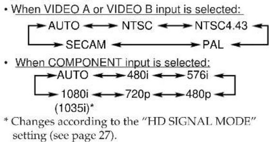
Setting the Receivable Signal Types
You can set the receivable signal types. Normally, select "AUTO."
A common setting will apply to both VIDEO A and B terminals, and a different setting will apply to the COMPONENT terminals.
1 Press MENU/EXIT (or MENU on the Monitor) to display the Main Menu.
2 Press ▲/▼ to move the cursor (▶) to "FUNCTION SELECT."
3 Press ▶ to display the Function Selection Menu.
* "PICTURE MODE" and "SIGNAL MODE" do not appear at the same time. "PICTURE MODE" appears when RGB input is selected, and one of the following signals comes in — RGB15K-50, RGB15K-60, PC98, VGA480-60, SVGA-56, SVGA-60, and XGA-60. On the other hand, "SIGNAL MODE" appears when VIDEO A, VIDEO B, or COMP. (component) input is selected.
4 Press ▲/▼ to move the cursor (▶) to "SIGNAL MODE."
5 Press ◀/▶ to select the receivable video signal type.
Each time you press the button, the receivable video signal type changes as follows:
flowchart
graph LR
    A["When VIDEO A or VIDEO B input is selected: AUTO ←→ NTSC ←→ NTSC4.43"] --> B["SECAM ←→ PAL ←"]
    C["When COMPONENT input is selected: AUTO ←→ 480i ←→ 576i"] --> D["1080i ←→ 720p ←→ 480p ←"]
    D --> E["(1035i)*"]
    style A fill:#f9f,stroke:#333
    style C fill:#f9f,stroke:#333
    style D fill:#f9f,stroke:#333
    style E fill:#ccf,stroke:#333
6 Press MENU/EXIT (or MENU on the Monitor) twice to exit the menu operations.
Setting the RGB Input
After connecting the playback device such as a PC to the RGB terminals, you have to specify which terminal you have connected the device to — RGB A (D-sub 15 pin) or RGB B (BNC) input.
- Without setting the RGB input correctly, you cannot show any picture though you select the RGB input.
1 Press MENU/EXIT (or MENU on the Monitor) to display the Main Menu.
2 Press ▲/▼ to move the cursor (▶) to "FUNCTION SELECT."
3 Press ▶ to display the Function Selection Menu.
* "PICTURE MODE" and "SIGNAL MODE" do not appear at the same time. "PICTURE MODE" appears when RGB input is selected, and one of the following signals comes in — RGB15K-50, RGB15K-60, PC98, VGA480-60, SVGA-56, SVGA-60, and XGA-60. On the other hand, "SIGNAL MODE" appears when VIDEO A, VIDEO B, or COMP. (component) input is selected.
4 Press ▲/▼ to move the cursor (▶) to "RGB INPUT."
5 Press ◀/▶ to select the correct RGB terminal you use.
Each time you press the button, the RGB input alternates between "A" and "B."
A: When connecting the playback device to the RGB A terminal (D-sub 15).
B: When connecting the playback device to the RGB B IN terminal (BNC).
6 Press MENU/EXIT (or MENU on the Monitor) twice to exit the menu operations.
Resetting the Function Selection Menu Settings
You can reset all the Function Selection Menu settings at a time.
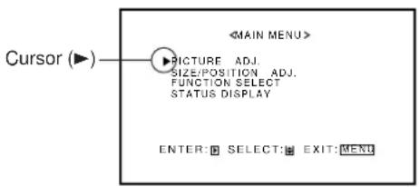
1 Press MENU/EXIT (or MENU on the Monitor) to display the Main Menu.
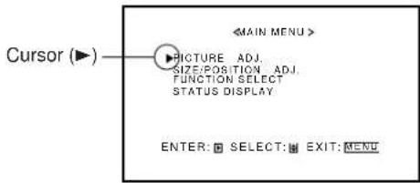
![Cursor (▶) MAIN MENU> ▶PICTURE ADJ. SIZE:POSITION ADJ. FUNCTION SELECT STATUS DISPLAY ENTER: SELECT: [REX: [MENU]](/content/2026/05/1142874/images/e1bc9387ba9c0ec979b5a6999c1817cfb321f4ee98b6cccf00775121d07616c2.jpg)
2 Press ▲/▼ to move the cursor (▶) to "FUNCTION SELECT."
3 Press ▶ to display the Function Selection Menu.
* "PICTURE MODE" and "SIGNAL MODE" do not appear at the same time.
"PICTURE MODE" appears when RGB input is selected, and one of the following signals comes in — RGB15K-50, RGB15K-60, PC98, VGA480-60, SVGA-56, SVGA-60, and XGA-60. On the other hand, "SIGNAL MODE" appears when VIDEO A, VIDEO B, or COMP. (component) input is selected.
4 Press ▲/▼ to move the cursor (▶) to "reset."
5 Press ▶.
The confirmation screen appears.
6 Press ▶ again to reset the adjustments.
To cancel the reset, press MENU/EXIT (or MENU on the Monitor).

To set the other convenient functions, use menus.
You can use the buttons either on the remote control or on Monitor for menu operations.
- Refer also to "Menu Classifications" on pages 33 and 35.
Showing On-screen Display
The input mode and signal type will be indicated on the screen.
- The following procedure can be done by using the buttons on the Monitor. You can also show these information by pressing DISPLAY on the remote control. (See page 14.)
1 Press MENU (or MENU/EXIT on the remote control) to display the Main Menu.
2 Press ▲/▼ to move the cursor (▶) to "STATUS DISPLAY."
3 Press ▶ to display the current input terminal and received signal type.
Ex. When selecting "VIDEO A" input
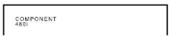
Ex. When selecting "COMPONENT" input
Ex. When selecting "RGB" input
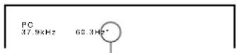
When the signal being input is a preset video mode, an “*” will be shown after the frequency.
Note:
- If you want to make these information appear automatically when you change the input mode, see "Showing the On-screen When Changing the Input Mode" on page 26.
Confirming the Use Time
You can confirm the hours of use on the Setup Menu.
This may be necessary when you ask for any service.
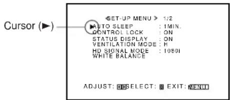
1 On the remote control: Press MENU/EXIT while holding VOLUME – to display the Setup Menu.
On the Monitor: Press MENU while holding ◀ to display the Setup Menu.
2 Keep pressing ▲/▼ until the second page of the Setup Menu appears.
- The Setup Menu consists of two pages. If you keep pressing ▲/▼, you can move to the other page from the current page.
3 Confirm the hour of use.
- The displayed value for the hours of use is divided by 100. To calculate the actual hours of use, multiply the displayed value by 100.
4 Press MENU/EXIT (or MENU on the Monitor) once to exit from the menu operations.
Notes:
- The value for the hours of use is added by one hour unit. If you use the monitor within one hour, it will not be added to the hours of use.
- The period when the monitor is on standby (the power lamp glows orange) will not be added to the hours of use.
Setting the Auto Sleep Function
This function allows you to turn off (into standby mode) automatically when no signal comes in for a certain period of time.
- The power lamp flashes (orange) while in the Sleep mode (standby).
- When signals come in while in the Sleep mode, the Monitor turns on (the power lamp glows green).
1 On the remote control: Press MENU/EXIT while holding VOLUME – to display the Setup Menu.
On the Monitor: Press MENU while holding ◀ to display the Setup Menu.

2 Press ▲/▼ to move the cursor (▶) to "AUTO SLEEP."
- The Setup Menu consists of two pages. If you keep pressing ▲/▼, you can move to the other page from the current page.
3 Press ◀/▶ to select the desired amount of time.
Select the number of minutes before the Monitor goes into standby mode after the signal has ceased to be supplied.
Each time you press the button, the amount of time changes as follows:
To cancel the Auto Sleep function, select "OFF."
4 Press MENU/EXIT (or MENU on the Monitor) once to exit from the menu operations.
Prohibiting the Monitor's Button Operations
This function allows you to prohibit the button operations on the Monitor to prevent malfunction or avoid tampering.
1 On the remote control: Press MENU/EXIT while holding VOLUME – to display the Setup Menu.
On the Monitor: Press MENU while holding ◀ to display the Setup Menu.
2 Press ▲/▼ to move the cursor (▶) to "CONTROL LOCK."
- The Setup Menu consists of two pages. If you keep pressing ▲/▼, you can move to the other page from the current page.
3 Press ◀/▶ to select the desired setting.
Each time you press the button, the Control Lock function alternates between "ON" and "OFF."
To cancel the Control Lock function, select "OFF."
4 Press MENU/EXIT (or MENU on the Monitor) once to exit from the menu operations.
Note:
• Even when the Control Lock function is in use, the following operations are possible:
- Operation to cancel the Control Lock function
- All operations from the remote control
Showing the On-screen When Changing the Input Mode
With this function, you can see the selected input mode and signal type when changing the input mode.
1 On the remote control: Press MENU/EXIT while holding VOLUME – to display the Setup Menu.
On the Monitor: Press MENU while holding ◀ to display the Setup Menu.
2 Press ▲/▼ to move the cursor (▶) to "STATUS DISPLAY."
- The Setup Menu consists of two pages. If you keep pressing ▲/▼, you can move to the other page from the current page.
3 Press ◀/▶ to select the desired setting.
Each time you press the button, the Status Display function alternates between "ON" and "OFF."
To cancel the Status Display function, select "OFF."
4 Press MENU/EXIT (or MENU on the Monitor) once to exit from the menu operations.
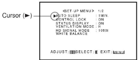
Mounting the Monitor Vertically
When mounting the Monitor vertically, the temperature inside the Monitor rises more than it is mounted horizontally. To provide better heat dissipation, it is necessary to perform the adjustment to switch fan speeds.
1 On the remote control: Press MENU/EXIT while holding VOLUME – to display the Setup Menu.
On the Monitor: Press MENU while holding ◀ to display the Setup Menu.
2 Press ▲/▼ to move the cursor (▶) to "VENTILATION MODE."
- The Setup Menu consists of two pages. If you keep pressing ▲/▼, you can move to the other page from the current page.
3 Press ◀/▶ to select "V."
Each time you press the button, the Ventilation Mode alternates between "H (horizontal mounting)" and "V (vertical mounting)."
4 Press MENU/EXIT (or MENU on the Monitor) once to exit from the menu operations.
Setting the High-Definition Signal Types
You can select one of the High-Definition (HD) signal types through the COMPONENT terminals — 1080i or 1035i. Normally set it to "1080i."
1 On the remote control: Press MENU/EXIT while holding VOLUME – to display the Setup Menu.
On the Monitor: Press MENU while holding ◀ to display the Setup Menu.
2 Press ▲/▼ to move the cursor (▶) to "HD SIGNAL MODE."
- The Setup Menu consists of two pages. If you keep pressing ▲/▼, you can move to the other page from the current page.
3 Press ◀/▶ to select the desired setting.
Each time you press the button, the HD signal type alternates between "1080i" and "1035i."
- You can select either "1080i" and "1035i" according to the HD signal you input — whichever gives you proportionally shaped pictures.
4 Press MENU/EXIT (or MENU on the Monitor) once to exit from the menu operations
Using the Pixel Shift Function
This function periodically shift the position (pixels) of the displayed picture on the screen so that you can avoid the screen from being burned in.
1 On the remote control: Press MENU/EXIT while holding VOLUME – to display the Setup Menu.
On the Monitor: Press MENU while holding ◀ to display the Setup Menu.
(To be continued on the next page)
2 Press ▲/▼ to move the cursor (▶) to "PIXEL SHIFT" (on the second page).
- The Setup Menu consists of two pages. If you keep pressing ▲/▼, you can move to the other page from the current page.
3 Press ◀/▶ to select the desired setting. Each time you press the button, the Pixel Shift function alternates between "ON" and "OFF." To cancel the Pixel Shift function, select "OFF."
4 Press MENU/EXIT (or MENU on the Monitor) once to exit from the menu operations.
Using the Power Save Function
You can use this function to reduce the electrical consumption and to extend the lifetime of the Monitor's screen.
• The brightness of the screen will be reduced.
1 On the remote control: Press MENU/EXIT while holding VOLUME – to display the Setup Menu.
On the Monitor: Press MENU while holding ◀ to display the Setup Menu.
2 Press ▲/▼ to move the cursor (▶) to "POWER SAVE" (on the second page).
- The Setup Menu consists of two pages. If you keep pressing ▲/▼, you can move to the other page from the current page.
3 Press ◀/▶ to select the desired setting. Each time you press the button, the Power Save function alternates between "ON" and "OFF." To cancel the Power Save function, select "OFF."
4 Press MENU/EXIT (or MENU on the Monitor) once to exit from the menu operations.
Preventing the Afterimage Effect
After showing the same still picture on the screen, reverse the color on the screen using this function so that you can avoid the screen from being burned in with the still picture.
1 On the remote control: Press MENU/EXIT while holding VOLUME – to display the Setup Menu.
On the Monitor: Press MENU while holding ◀ to display the Setup Menu.
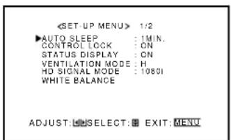
![Cursor (▶) 1/2 AUTO SLEEP : 1MIN. CONTROL LOCK : ON STATUS DISPLAY : ON VENTILATION MODE : H HD SIGNAL MODE : 10801 WHITE BALANCE ADJUST: SELECT: EXIT: [MENU]](/content/2026/05/1142874/images/7ca0702def9aab6d3b8e2448ecff0ed45394a2ff42fa4bfad602f62b58101324.jpg)
2 Press ▲/▼ to move the cursor (▶) to "COLOR-REVERSE" (on the second page).
- The Setup Menu consists of two pages. If you keep pressing ▲/▼, you can move to the other page from the current page.
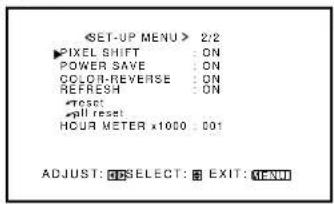
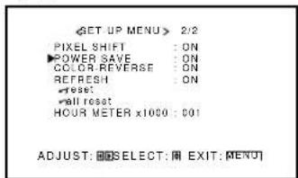
![2/2 PIXEL SHIFT : ON POWER SAVE : ON ▶COLOR-REVERSE : ON REFRESH : ON *reset: *null reset HOUR METER x1000 : 001 ADJUST: [ ] SELECT: [ ] EXIT: MENU](/content/2026/05/1142874/images/9a2972733eb41b1c247c4e1b2d454aaa8337e00a355106da65a2d82a98285a1a.jpg)
3 Press ◀/▶ to select "ON" while showing the still picture so that you can avoid the screen from being burned in with the still picture.
Each time you press the button, the Color-Reverse function alternates between "ON" and "OFF."
To cancel the Color-Reverse function, select "OFF."
4 Press MENU/EXIT (or MENU on the Monitor) once to exit from the menu operations.
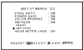
Refreshing the Screen
After the power is turned off, a whitish image may be left on the screen. In that case, leave the monitor in a white back state for a while, and the image will disappear.
1 On the remote control: Press MENU/EXIT while holding VOLUME – to display the Setup Menu.
On the Monitor: Press MENU while holding ◀ to display the Setup Menu.
2 Press ▲/▼ to move the cursor (▶) to "REFRESH" (on the second page).
- The Setup Menu consists of two pages. If you keep pressing ▲/▼, you can move to the other page from the current page.
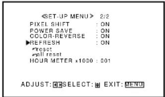
3 Press ◀/▶ to select the desired setting.
The Setup Menu disappears, and the white screen appears.
To cancel the Refresh function
Repeat steps 1 and 2, then select "OFF" by pressing ◀/▶.
Resetting All the Setup Menu Settings
You can reset all the following Setup Menu settings at a time, except the use time of the source lamp (HOUR METER).
1 On the remote control: Press MENU/EXIT while holding VOLUME – to display the Setup Menu.
On the Monitor: Press MENU while holding ◀ to display the Setup Menu.
2 Press ▲/▼ to move the cursor (▶) to "reset" (on the second page).
- The Setup Menu consists of two pages. If you keep pressing ▲/▼, you can move to the other page from the current page.
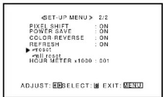
3 Press ▶.
The confirmation screen appears.
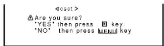
4 Press ▶ again to reset all the Setup Menu settings.
To cancel the reset, press MENU/EXIT (or MENU on the Monitor).

Resetting All the Menu Settings
You can reset all the Menu settings and adjustments at a time, except the use time of the source lamp (HOUR METER).
1 On the remote control:
Press MENU/EXIT while holding VOLUME – to display the Setup Menu.
On the Monitor:
Press MENU while holding ◀ to display the Setup Menu.
2 Press ▲/▼ to move the cursor (▶) to "all reset" (on the second page).
- The Setup Menu consists of two pages. If you keep pressing ▲/▼, you can move to the other page from the current page.
3 Press ▶.
The confirmation screen appears.
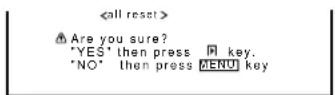
4 Press ▶ again to reset all the Menu settings and adjustments.
To cancel the reset, press MENU/EXIT (or MENU on the Monitor).
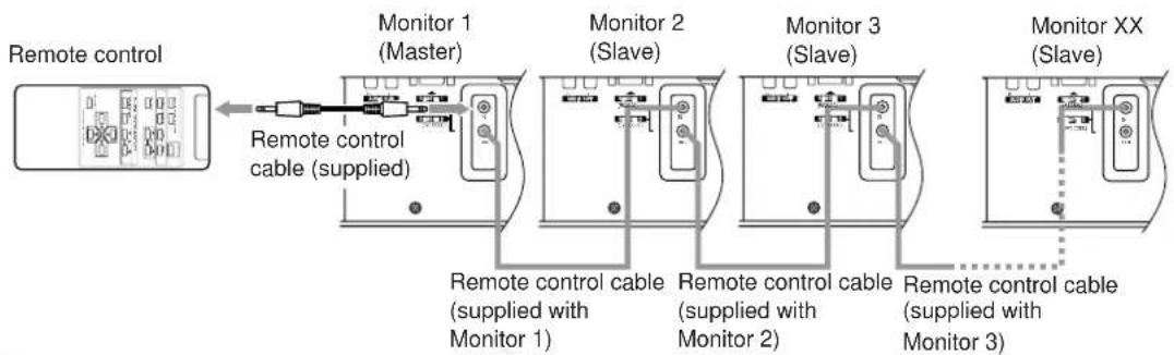
Serial Connections and Operations
When the Monitors are serially connected, you can control all of them at the same time (simultaneous operation) or control them one by one separately (individual operation).
For individual operation, you have to assign an ID number to each of the Monitors.
For the purpose of explanation, we will call Monitor 1 as a Master and Monitor 2 and subsequent Monitors as Slaves.
Connecting the Remote Control Cables
flowchart
graph LR
    A["Remote control"] --> B["Monitor 1 (Master)"]
    B --> C["Monitor 2 (Slave)"]
    C --> D["Monitor 3 (Slave)"]
    D --> E["Monitor XX (Slave)"]
    B --> F["Remote control cable (supplied)"]
    C --> G["Remote control cable (supplied with Monitor 1)"]
    D --> H["Remote control cable (supplied with Monitor 2)"]
    E --> I["Remote control cable (supplied with Monitor 3)"]
Notes:
- Do not connect the last monitor to Monitor 1.
- When operating with a wired remote control, connect it to the REMOTE 2 (JVC CODE) input terminal of Monitor 1.
- When Monitors are serially connected, Monitor 2 and subsequent Monitors cannot be directly controlled with a wireless remote control.
- Even after the Monitors are serially connected, each of them can be operated using the buttons on the Monitor. However, you cannot perform simultaneous or individual operation even with the buttons on Master Monitor.
- When performing simultaneous or individual operation, use the remote control.
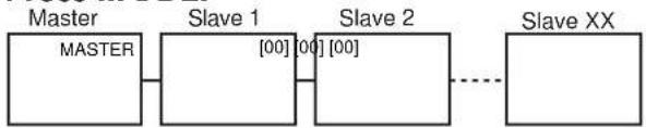
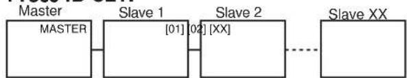
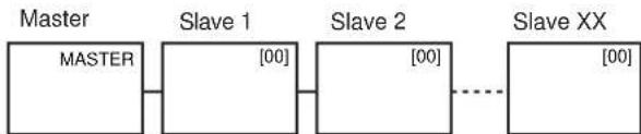
Assigning ID Numbers
The following procedure should be performed slowly and securely.
1 Turn on all the connected Monitors.
2 Press MODE.
flowchart
graph LR
    A["Master"] --> B["Slave 1"]
    B --> C["Slave 2"]
    C --> D["Slave XX"]
    style A fill:#f9f,stroke:#333
    style B fill:#ccf,stroke:#333
    style C fill:#cfc,stroke:#333
    style D fill:#fcc,stroke:#333
On Master Monitor screen, "MASTER" is displayed, and "[00]" is displayed on all of Slave Monitor screens.
3 Press ID SET.
flowchart
graph LR
    A["Master"] --> B["Slave 1"]
    B --> C["Slave 2"]
    C --> D["Slave XX"]
    B -->|[01]| C
    C -->|[02]| B
    D -.-> E["..."]
On the Slave Monitor screens, "[01]", "[02]", "[03]", — and so on will be displayed in the order of connection.
Notes:
- When a maximum number of 20 Monitors are connected, it will take approx. 10 seconds for ID numbers to be displayed on all the screens.
- If "[00]" is displayed on all the Monitor screens or if some of the Monitors have no indication in step 1, press MODE to turn off the indications on all Monitor screens, and then press MODE again.
- When performing simultaneous or individual operation, use the remote control.
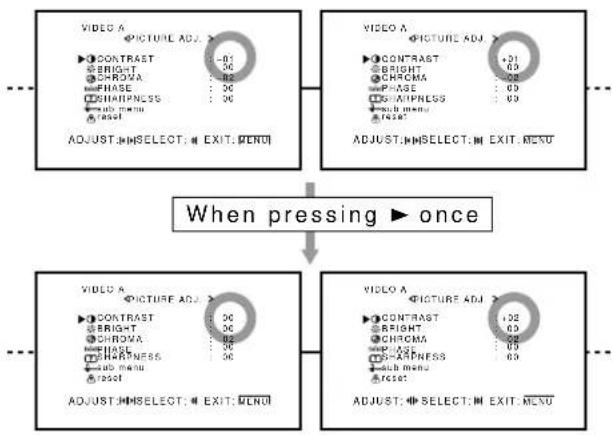
Operating the Monitors Simultaneously
- Check that no ID number is shown on the screens. If any ID numbers are shown, press MODE to erase them.
- The following procedure should be performed slowly and securely.
Example: When adjusting "CONTRAST":
1 Press MENU/EXIT to display the Main Menu.
The Main Menus appear on all the connected Monitors' screens.
2 Press ▲/▼ to move the cursor (▶) to "PICTURE ADJ."
3 Press ▶ to display the Picture Adjustment Menu.
The Picture Adjustment Menus appear on all the connected Monitors' screens.
4 Press ▲/▼ to move the cursor (▶) to "CONTRAST."
5 Press ◀/▶ to make an adjustment.
At this time, if the Monitors have different "CONTRAST" settings, the adjustment is made, based on the different settings.
flowchart
graph TD
    A["VIDEO A"] --> B["CONTRAST: -01"]
    A --> C["BRIGHT: 06"]
    A --> D["CHROMA: 02"]
    A --> E["FHASE: 06"]
    A --> F["WHIPNESS: 06"]
    A --> G["sub menu: reset"]
    H["VIDEO A"] --> I["CONTRAST: +01"]
    H --> J["BRIGHT: 03"]
    H --> K["CHROMA: 05"]
    H --> L["FHASE: 09"]
    H --> M["AMIPNESS: 09"]
    H --> N["sub menu: reset"]
    O["ADJUST: SELECT: EXIT: MENU"] --> P["When pressing ▶ once"]
    Q["VIDEO A"] --> R["CONTRAST: 06"]
    Q --> S["BRIGHT: 03"]
    Q --> T["CHROMA: 05"]
    Q --> U["FHASE: 09"]
    Q --> V["AMIPNESS: 09"]
    Q --> W["sub menu: reset"]
    X["ADJUST: SELECT: EXIT: MENU"] --> Y["When pressing ▶ once"]
6 Press MENU/EXIT twice to exit from the menu operations.
Operating the Monitors Individually
The following procedure should be performed slowly and securely.
1 Press MODE to display the ID numbers on all the connected Monitors' screens.
flowchart
graph LR
    A["Master"] --> B["Slave 1 [00"]]
    B --> C["Slave 2 [00"]]
    C -.-> D["Slave XX [00"]]
2 Press ID +/- to select the Monitor you want to operate.
Example: To select "[02]":
Press ID + twice.
Slave 2's ID number "[02]" is highlighted.
* The selected ID number will be also shown on the Master Monitor (in this example, "MASTER→[02]").
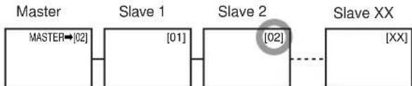
flowchart
graph LR
    A["MASTER"] --> B["Slave 1"]
    B --> C["Slave 2"]
    C --> D["Slave XX"]
    style C stroke-dasharray: 5 5
3 Perform any desired operations, such as adjusting menu items.
Notes:
- If “[00]” is displayed on all the Monitor screens or if some of the Monitor screens have no indication in step 1, press MODE to turn off the indications on all screens, and then press MODE again.
- If the ID number of the Monitor selected in step 2 is not highlighted or if the ID numbers of more than one Monitor are highlighted, press MODE to clear the ID numbers, and then start the procedure again from the beginning.
Main Menu
Main Menu
flowchart
graph TD
A["MAIN MENU"] --> B["VIDEO A <PICTURE ADJ."]
B --> C["Size/Position Adjustment Menu"]
C --> D["Function Selection Menu"]
D --> E["Status Display"]
subgraph Video_A
B1["CONTRAST :+01"] --> B2["BRIGHT :+01"]
B3["CHROMA :+01"] --> B4["PHASE :+01"]
B5["SHARPNESS :+01"] --> B6["SHARPNESS :+01"]
end
subgraph Size/Position Adjustment
C1["H SIZE :+01"] --> C2["H POSITION :+01"]
C3["V SIZE :+01"] --> C4["V POSITION :+01"]
C5["CLOCK PHASE :+01"] --> C6["CLOCK PHASE :+01"]
C7["ADJUST: SELECT: EXIT: MENU"] --> C8["ADJUST: SELECT: EXIT: MENU"]
end
subgraph Function_Selection
D1["FUNCTION SELECT"]
D2["COLOR TEMP :HIGH"] --> D3["PICTURE MODE :STILL"]
D4["ASPECT :PANORAMA"] --> D5["SIGNAL MODE :AUTO"]
D6["RGB INPUT :A"] --> D7["ADJUST: SELECT: EXIT: MENU"]
end
subgraph Status_Display
E1["VIDEO A NTSC"] --> E2["Input currently selected"]
E3["Input video signal"] --> E4["Ex. When "VIDEO A" input is selected"]
A --> B
B --> C
C --> D
D --> E
E --> F
PICTURE ADJ. (Picture adjustment): See page 16.
CONTRAST Adjusts the contrast of the picture.
BRIGHT Adjusts the brightness of the picture.
CHROMA*** Adjusts the color density of the picture.
PHASE* Adjusts the color phase.
SHARPNESS Adjusts the outlines of the picture.
sub menu Displays the fine adjustment bar.
reset Resets the Picture Adjustment Menu settings to defaults.
SIZE/POSITION ADJ.: See page 17.
H.SIZE Adjusts the horizontal screen size.
H. POSITION Adjusts the horizontal screen position.
V. SIZE Adjusts the vertical screen size.
V. POSITION Adjusts the vertical screen position.
CLOCK PHASE** Adjusts to eliminate stripes or flickering.
Normally, no adjustment is needed.
sub menu Displays the fine adjustment bar.
reset Resets Size/position Adjustment Menu settings to defaults.
FUNCTION SELECT: See pages 19 to 23.
COLOR TEMP. Adjusts the color temperature.
Use when the picture is reddish or bluish.
PICTURE MODE**** Selects the picture quality suited to either the still picture or the moving picture.
ASPECT Selects the horizontal to vertical ratio of the screen.
SIGNAL MODE*** Selects a color system (NTSC, NTSC 4.43, PAL, SECAM) when VIDEO A or VIDEO B input is selected.
- Selects a scan system — 480i, 576i, 480p, 720p, 1080i (1035i) — when COMPONENT input is selected. Normally, set to "AUTO."
RGB INPUT Sets the correct RGB terminal you use.
reset Resets the Function Selection Menu settings to defaults.
* Adjustment is not possible when RGB input is selected.
** Adjustment is only possible when viewing NTSC signal through the VIDEO A or B terminal.
*** Adjustment is only possible when RGB input is selected.
***Adjustment is only possible when the RGB15K-50, RGB15K-60, PC98, VGA480-60, SVGA-56, SVGA-60, or XGA-60 signals come in.
Setup Menu
flowchart
graph TD
A["<SET-UP MENU> 1/2"] --> B["ADJUST: SELECT: EXIT: MENU"]
C["AUTO SLEEP : 1MIN."] --> B
D["CONTROL LOCK : ON"] --> B
E["STATUS DISPLAY : ON"] --> B
F["VENTILATION MODE : H"] --> B
G["HD SIGNAL MODE : 1080i"] --> B
H["WHITE BALANCE"] --> B
I["R GAIN : 000"] --> J["ADJUST: SELECT: EXIT: MENU"]
K["G GAIN : +001"] --> J
L["B GAIN : -002"] --> J
M["sub menu"] --> J
N["reset"] --> J
O["<reset>"] --> P["Are you sure? "YES" then press key, "NO" then press MENU key"]
Q["<set>"] --> R["<set>"]
S["<set> 2/2"] --> T["ADJUST: SELECT: EXIT: MENU"]
U["PIXEL SHIFT : ON"] --> V["ADJUST: SELECT: EXIT: MENU"]
W["POWER SAVE : ON"] --> V
X["COLOR-REVERSE : ON"] --> V
Y["REFRESH : ON"] --> V
Z["reset"] --> V
AA["all reset : HOUR METER x1000 : 001"] --> V
AB["Are you sure? "YES" then press key, "NO" then press MENU key"] --> AC["<all reset>"]
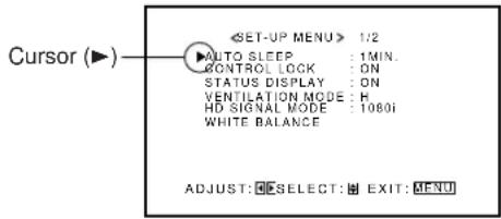
AUTO SLEEP Sets the length of time before standby mode is automatically assumed after the input signal has stopped being supplied. (See page 25.)
CONTROL LOCK Sets the Monitor so that it cannot be operated with the buttons on itself. (See page 26.)
STATUS DISPLAY Sets if you want the input terminal and the type of signal to be indicated on the screen just after inputs are switched. (See page 26.)
VENTILATION MODE Adjusts the cooling fan speed according to the Monitor mounting method. (See page 27.)
HD SIGNAL MODE Select the High-Definition (HD) signal type. (See page 27.)
WHITE BALANCE Adjusts R GAIN, G GAIN and B GAIN finely each for "HIGH" and "LOW" settings of the color temperature. (See page 19.)
PIXEL SHIFT Sets a screen saver. (See page 27.)
POWER SAVE Sets the power save function. (See page 28.)
COLOR-REVERSE Use to reverse the color of the still picture to prevent its afterimage from being left on the screen. (See page 29.)
REFRESH Use to eliminate afterimages on the screen. (See page 29.)
reset Resets the Setup Menu settings to defaults. (See page 29.)
all reset Resets the all menu settings and adjustments to defaults. (See page 30.)
HOUR METER Use to confirm the hours of use. (See page 25.)
Solutions to common problems related to the Monitor are described here. If none of the solutions presented here solves the problem, unplug the Monitor and consult an authorized dealer or service center.
| Symptom Probable cause Corrective action Page | |||
| Power is not supplied. | • Is the power cord disconnected? | • Insert the power cord (plug) firmly. | 12 |
| • Is the MAIN POWER switch turned on? | • Turn on the MAIN POWER switch. | 14 | |
| Video image does not appear, or audio sound does not occur. | • Is the correct input selected? | • Select the correct input by pressing VIDEO A, VIDEO B, COMPO. and RGB on the remote control (or INPUT on the Monitor). | 14 |
| • Are the devices connected correctly? | • Connect the devices correctly. | 12, 13 | |
| • Are signals being supplied from the connected devices? | • Set the devices correctly. | — | |
| • Is RGB INPUT set correctly if using the RGB terminals? | • Set it correctly. | 23 | |
| • Are input signals (scanning frequency, etc.) appropriate? | • Check if the signal is appropriate (scanning frequency, etc.), and input the appropriate signal. | 11 | |
| • Is brightness adjusted correctly? | • Adjust brightness on the menu. | 16 | |
| • Is volume set at minimum? | • Adjust volume. | 14 | |
| • Are the diagnostic lamps turned on? | • Refer to “Self-diagnostic indication,” and take an appropriate action. | 37 | |
| The picture becomes blurred. | • Is the signal RGB input? | • Adjust CLOCK PHASE using the menu. | 17 |
| Colour is abnormally dark or bright. | • Is brightness adjusted correctly? | • Adjust BRIGHT (brightness) using the menu. | 16 |
| Colour is poor or unstable. | • Is picture quality (colour density, etc.) adjusted correctly? | • Adjust PICTURE using the menu. | 16 |
| • Is the correct broadcast system (colour system) selected? | • Set SIGNAL MODE (colour system) to “AUTO.” | 22 | |
| • Are signals (scanning frequency, etc.) to connected devices appropriate? | • Check if the signal is appropriate (scanning frequency, etc.), and input the appropriate signal. | 11 | |
| The picture is cut or shifted toward one side. | • Is the size or position of the screen adjusted properly? | • Adjust H.SIZE, V.SIZE, H.POSITION or V.POSITION using the menu. | 17 |
| The remote control does not work. | • Are the batteries correctly set? | • Insert batteries correctly, observing the polarities (⊕ and ⊖). | 9 |
| • Are the batteries exhausted? | • Replace with new batteries. | 9 | |
| • Is there any object blocking the path between the remote control and remote sensor? | • Remove any blocking object. | — | |
| • Is the Monitor too far away from you? | • Move toward the Monitor, then operate the remote control. | — | |
| • Is the Monitor connected serially to another Monitor (Serial Connection)? | • Only Master Monitor can be controlled by the remote control when connected serially. | 31 | |
| The buttons on the Monitor do not work. | • Is the Control Lock function in use? | • Set the Control Lock function to “OFF” using the menu. | 26 |
Self-diagnostic Indication
The screen monitor may automatically turn off and self-diagnostic lamps next to the power lamp may light or flash. When something abnormal occurs with the Monitor, this function informs you of the condition of the Monitor with self-diagnostic lamps, allowing for smooth service work. If the self-diagnostic lamps glow or flash in red, use the following procedure before consulting the dealer where you purchased the Monitor.
1 Check which lamps are lighting or flashing.
On the Self-diagnostic Report Sheet (below), check the box next to "Lights" or "Flashes" of the corresponding lamp or lamps.
- Depending on a particular case, only one lamp may light or flash, or all three lamps may do so.
2 Turn off the MAIN POWER switch on the back of the Monitor.
3 Unplug the power cord.
4 Call your dealer and tell which lamps are lighting or flashing. (Copy and fax the Self-diagnostic Report Sheet below.)
Note:
- If you turn on the Monitor soon after turning it off (or after recovering from a brief power interruption), the self-diagnostic lamps may light (or flash), and no image may appear on the screen. In this case, turn off the Monitor again, wait for about 10 seconds, then turn it on again. If no self-diagnostic lamps light or flash, you can operate and use the Monitor as usual.
Store name where you purchased the Monitor
To
Model Name:
Plasma Display Monitor
GD-V4210PZW/GD-V4210PZW-G
GD-V4210PCE/GD-V4210PCE-G
GD-V4211PCE
Self-diagnostic Report Sheet
The self-diagnostic lamps light or flash as listed on the following table. Please give me immediate advice or service if necessary.
| Self-diagnostic lamps | |||
| NO. | Lamp position C | conditions | |
| Upper1 | ☐ Lights | ☐ Flashes | |
| 2 M | iddle | ☐ Lights | ☐ Flashes |
| 3 | Lower | ☐ Lights | ☐ Flashes |
| Your Name: | |
| Telephone No.: | |
| Address: |
| Model name GD-V4210PZW / GD | V-4210PZW-G GD-V4210PCE / GD-V4210PCE-G / GD-V4211PCE | |||
| General | Frame color GD-V4210PZW: Silver | GD-V4210PCE / GD-V4211PCE: SilverGD-V4210PZW-G: Gray GD-V4210PCE-G: Gray | ||
| Screen size Type 42 wide format | ||||
| Aspect ratio 16:9 (Wide format) | ||||
| Number of pixels displayed 853 (H) x 480 (V) | ||||
| Number of colors displayed 16.77 million (256 colors for each of RGB) | ||||
| Effective screen size 92.1 cm x 51.8 cm (36-3/8" x 20-1/2"), 105.7 cm (41-5/8")(W x H, Diagonally) | ||||
| Weight 35.8 kg (78.8 lbs.) | ||||
| External dimensions 103.5 cm x 64.0 cm x 8.9 cm (40-3/4" x 25-1/4" x 3-5/8")(W x H x D) * Excluding protruding parts | ||||
| Power requirements | AC 120 V / AC 230 V, 50 Hz/60 Hz | |||
| Rated input current | 3.5 A (AC 120 V) / 1.9 A (AC 230 V) | |||
| Compatible systemsVIDEO A, B inputCOMPONENT input | NTSC, NTSC 4.43, PAL, SECAM480i, 576i, 480p, 720p, 1080i (1035i) | ____*1____*1 | ||
| Audio power output | INTERNAL: 2 W + 2 W (TYP at impedance 8 Ω)EXTERNAL: 3 W + 3 W (TYP at impedance 6 Ω) | |||
| Built-in speakers | 2 pcs., 4 cm x 7 cm oval-shaped, impedance 6 Ω | |||
| Operating conditions | Temperature: 0 °C to 40 °CRelative humidity: 20 % to 80 % (non-condensation) | |||
| Input/output terminals*1 | AV terminals*1 | VIDEO AVideo inputVideo outputAudio input | BNC terminal x 1, 1 V(p-p), 75 ΩBNC terminal x 1, 1 V(p-p), 75 ΩPin jack terminal x 2 (L/R)500 mV(rms), high impedance | ____*1____*1____*1 |
| VIDEO BY/C inputVideo inputAudio input | Y/C terminal x 1Y: 1 V(p-p), 75 ΩC: 0.286 V(p-p), 75 Ω (for NTSC)C: 0.3 V(p-p), 75 Ω (for PAL/SECAM)Pin jack terminal x 1, 1 V(p-p), 75 ΩPin jack terminal x 2 (L/R)500 mV(rms), high impedance | ____*1____*1____*1 | ||
| COMPONENTCOMPONENT inputAudio input | BNC terminal x 3Y: 1 V(p-p), 75 ΩPB/B-Y: 0.7 V(p-p), 75 ΩPR/R-Y: 0.7 V(p-p), 75 ΩPin jack terminal x 2 (L/R)500 mV(rms), high impedance | ____*1____*1 | ||
| Model name GD-V4210PZW / GD-V4210PZW-G GD-V4210PCE / GD-V4210PCE-G /GD-V4211PCE | ||||
| Input/output terminals*1 | RGB terminals | RGB ARGB input D-sub 3-row15-pin terminal x 1,Video signal: 0.7 V(p-p), 75 ΩSync signal: TTL level | ||
| RGB BRGB input BNC terminal x 5 (Bridge connection possible, auto termination)Analog RGB:R: 0.7 V(p-p), 75 Ω G: 0.7 V(p-p), 75 Ω B: 0.7 V(p-p), 75 ΩG on sync: 1 V(p-p), 75 Ω (negative sync)Horizontal sync/Composite sync (HD/Cs):HD: 1 V(p-p) to 5 V(p-p), high impedance (positive/negative polarity)Cs: 1 V(p-p) to 5 V(p-p), high impedance (positive/negative polarity)Vertical sync (VD):VD: 1 V(p-p) to 5 V(p-p), high impedance (positive/negative polarity) | ||||
| RGB output BNC terminal x 5 (Loop through output for bridge connection) | ||||
| AUDIOAudio input Pin jack terminal x 2 (L/R)500 mV(rms), high impedance (for RGB A or RGB B) | ||||
| REMOTE 1 (RS232C) terminal D-sub 9-pin terminal x 1 | ||||
| REMOTE 2 (JVC CODE) Stereo mini jack terminal x 2IN/OUT terminals | ||||
| SPEAKER OUT terminal | Impedance 6 Ω to 16 Ω | |||
| AUDIO output terminal Pin jack terminal x 2 (L/R)Output impedance 600 Ω | ||||
*1 GD-V4210PCE, GD-V4210PCE-G, and GD-V4211PCE do not have the following input terminals – VIDEO A, VIDEO B, and COMPONENT.
You need to install the video interface kit (IF-C421P1W), which is separately purchased, to reproduce input images for VIDEO A, VIDEO B, and COMPONENT.
- For easy understanding, pictures and illustrations are shown by being emphasized, omitted or composed, and may be more or less different from actual products.
- Design and specifications are subject to change without notice.
- IBM and IBM PC are registered trademarks of International Business Machines Corporation. Macintosh is registered trademarks of Apple Computer, Inc.
All other product names mentioned herein are used for identification purposes only, and may be the trademarks or registered trademarks of their respective companies.
Options (not supplied)
Stand Unit TS-C420P1W, TS-C420P4W, TS-C420P5W, TS-C420P7W
Wall Mounting Unit TS-C420P2W, TS-C420P6W
Ceiling suspension Unit TS-C420P3W
Video Interface Kit IF-C421P1W (Only for GD-V4210PCE, GD-V4210PCE-G, and GD-V4211PCE)
Notice on transportation
This Monitor is precision equipment and needs dedicated packing material for transportation.
Never use any packing material supplied from other than JVC or JVC-authorized dealers.
Pin assignment (Specifications for terminals)
- Y/C terminal
- RS-232C terminal
This is a female type connector.
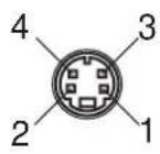
| Pin number | Signal name |
| 1 GND (Y) | |
| 2 GND (C) | |
| 3 | Y |
| 4 | C |
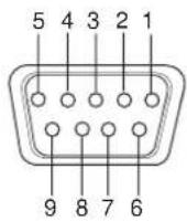
| Pin number | Signal name | Pin number | Signal name |
| 1 DCD | 6 DSR | ||
| 2 | RD | 7 | RTS |
| 3 | TD | 8 CTS | |
| 4 DTR | 9 | RI | |
| 5 GND |
- RGB Input Terminal
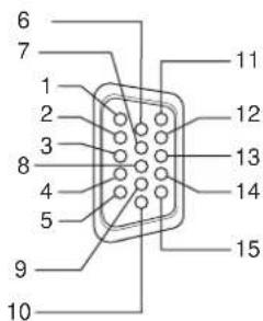
| Pin number Signal name | Pin number Signal name | ||
| 1 Red | 9 N/C | ||
| 2 Green | 10 GND | ||
| 3 | B | I 11 GND | u e |
| 4 N/C | 12 | N/C | |
| 5 GND | 13 | HD/Cs | |
| 6 GND | 14 | VD | |
| 7 GND | 15 | N/C | |
| 8 GND | External | GND | |
Dimensions
Top view
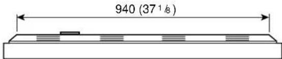
Front view
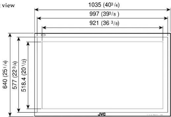
Side view
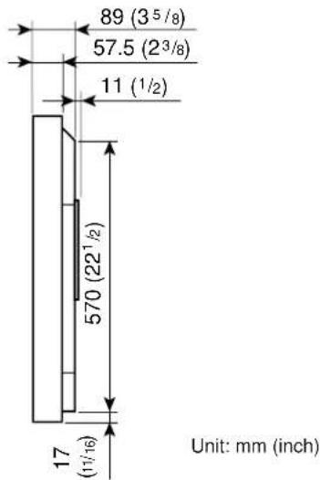
- Contents
- FCC NOTICE
- ■ GD-V4210PZW / GD-V4210PZW-G / GD-V4210PCE / GD-V4210PCE-G
- ■ GD-V4211PCE
- EUROPE EMC STANDARD NOTICE
- IMPORTANT INFORMATION
- IMPORTANT SAFEGUARDS
- Remote Control
- Monitor: Front View
- Remote sensor/power lamp
- Self-diagnostic lamps (page 37)
- ◀/▶/▲/▼ buttons
- MENU button
- INPUT button (page 14)
- POWER button (page 14)
- Monitor: Rear Views
- RGB B input/output terminals (page 12)
- Notes:
- 9RGB A input terminal (D-sub, 15-pin) (page 12)
- AUDIO input terminals (pin jack)
- 11VIDEO A terminals (page 13)\*
- Note:
- 12VIDEO B terminals (page 13)\*
- 13COMPONENT input terminals (page 13)\*
- Checking the Accessories
- Installing the Batteries
- Remove the back cover.
- Place the batteries.
- Replace the back cover as illustrated.
- Precautions for using batteries
- When installing the Monitor on a stand
- Take measures against the Monitor from overturning:
- When mounting the Monitor on the wall
- When hanging the Monitor from the ceiling
- Precautions
- Available Signals
- Video signals
- Computer signals (Preset and user-defined video modes)
- Connection Examples
- AV connections
- Daily Operations
- Turn on the main power.
- Turn on the power.
- Select an input.
- Adjust the volume.
- To turn off the volume immediately
- To make the screen indication appear
- Changing the Aspect Ratio
- Precautions for using the screen mode switching function
- Press ASPECT to select the screen size
- Adjusting the Picture Quality
- To make an adjustment while viewing the adjustment bar
- To reset the adjustments
- Adjusting the Screen Size and Position
- Press MENU/EXIT (or MENU on the Monitor) to display the Main Menu.
- Press ▲/▼ to move the cursor (▶) to "SIZE/POSITION ADJ."
- Press ▶ to display the Size/Position Adjustment Menu.
- Press ▲/▼ to move the cursor (▶) to the item you want to adjust.
- Adjusting the Color Temperature
- Adjusting the White Balance
- To make an adjustment while viewing the adjustment bars
- Changing the Picture Mode
- Press ▲/▼ to move the cursor (▶) to "FUNCTION SELECT."
- Press ▶ to display the Function Selection Menu.
- Press ▲/▼ to move the cursor (▶) to "PICTURE MODE."
- Press ◀/▶ to select the picture mode you want.
- Press MENU/EXIT (or MENU on the Monitor) twice to exit from the menu operations.
- Press ▲/▼ to move the cursor (▶) to "ASPECT."
- Press ◀/▶ to select an aspect ratio you want.
- Setting the Receivable Signal Types
- Setting the RGB Input
- Resetting the Function Selection Menu Settings
- Showing On-screen Display
- Confirming the Use Time
- Setting the Auto Sleep Function
- Prohibiting the Monitor's Button Operations
- Showing the On-screen When Changing the Input Mode
- Mounting the Monitor Vertically
- Setting the High-Definition Signal Types
- Using the Pixel Shift Function
- Press ▲/▼ to move the cursor (▶) to "PIXEL SHIFT" (on the second page).
- Using the Power Save Function
- Preventing the Afterimage Effect
- Refreshing the Screen
- Resetting All the Setup Menu Settings
- Resetting All the Menu Settings
- On the remote control:
- Press ▲/▼ to move the cursor (▶) to "all reset" (on the second page).
- Press ▶.
- Press ▶ again to reset all the Menu settings and adjustments.
- Serial Connections and Operations
- Connecting the Remote Control Cables
- Assigning ID Numbers
- Turn on all the connected Monitors.
- Press MODE.
- Press ID SET.
- Operating the Monitors Simultaneously
- Operating the Monitors Individually
- Main Menu
- Setup Menu
- Self-diagnostic Indication
- Check which lamps are lighting or flashing.
- Turn off the MAIN POWER switch on the back of the Monitor.
- Unplug the power cord.
- Call your dealer and tell which lamps are lighting or flashing. (Copy and fax the Self-diagnostic Report Sheet below.)
- Self-diagnostic Report Sheet
- Options (not supplied)
- Notice on transportation
- Pin assignment (Specifications for terminals)
- Dimensions
Brand : JVC
Model : GD-V4210PCE
Category : Television