
VS1912 - Video switch ATEN - Free user manual and instructions
Find the device manual for free VS1912 ATEN in PDF.


| Product Type | 12-Port DP Video Wall Media Player |
| Brand | ATEN |
| Model | VS1912 |
| Video Input | 1 x HDMI Type A Female |
| Video Output | 12 x DisplayPort 1.1 Female |
| Maximum Resolution | 1920 x 1080 per display (1080p) |
| Audio Output | 1 x 3.5 mm Stereo Jack Female |
| Control Ports | 2 x RS-232 DB-9 Female (Baud rate 38400-19200) |
| Ethernet | 2 x RJ-45 Female (1 DHCP, 1 Static) |
| USB Ports | 2 x USB 3.0, 4 x USB 2.0 |
| Power Input | 100-240 VAC; 50-60 Hz; 3.0 A |
| Power Consumption | 400W (at 120V or 230V) |
| Dimensions (L x W x H) | 43.00 x 27.00 x 4.40 cm |
| Weight | 5.75 kg (chassis only) |
| Housing Material | Metal |
| Operating Temperature | 0-40°C |
| Storage Temperature | -20-60°C |
| Humidity | 0-80% RH, Non-condensing |
| Supported Display Layouts | Up to 12 displays, symmetrical and asymmetrical layouts |
| Widget Support | Video, Images, Flash, Webpage, Text, Banner, Clock, RSS, RTSP Streaming, Video Capture |
| Rack Mountable | Yes (1U) |
| Firmware Upgradeable | Yes |
Frequently Asked Questions - VS1912 ATEN
User questions about VS1912 ATEN
0 question about this device. Answer the ones you know or ask your own.
Ask a new question about this device
Download the instructions for your Video switch in PDF format for free! Find your manual VS1912 - ATEN and take your electronic device back in hand. On this page are published all the documents necessary for the use of your device. VS1912 by ATEN.
USER MANUAL VS1912 ATEN
12-Port DP Video Wall Media Player
VS1912
User Manual

natural_image
Exterior view of a black OP Video Wall Audio Layer network device (no visible text or symbols on the device body)FCC Information
FEDERAL COMMUNICATIONS COMMISSION INTERFERENCE
STATEMENT: This equipment has been tested and found to comply with the limits for a Class A digital device, pursuant to Part 15 of the FCC Rules. These limits are designed to provide reasonable protection against harmful interference when the equipment is operated in a commercial environment.
This equipment generates, uses, and can radiate radio frequency energy and, if not installed and used in accordance with the instruction manual, may cause harmful interference to radio communications. Operation of this equipment in a residential area is likely to cause harmful interference in which case the user will be required to correct the interference at his own expense.
The device complies with Part 15 of the FCC Rules. Operation is subject to the following two conditions: (1) this device may not cause harmful interference, and (2) this device must accept any interference received, including interference that may cause undesired operation.
FCC Caution: Any changes or modifications not expressly approved by the party responsible for compliance could void the user's authority to operate this equipment.
CE Warning: This is a class A product. In a domestic environment this product may cause radio interference in which case the user may be required to take adequate measures.
KCC Statement
This product is RoHS compliant.

Safety
This product has been classified as Information Technology Equipment.
SJ/T 11364-2006
The following contains information that relates to China.
Be sure to register your product at our online support center:
International http://eservice.aten.com
Telephone Support
For telephone support, call this number:
| International 886-2-86 | 92-6959 |
| China 86-400-810-0-8 | 10 |
| Japan 81-3-5615-5811 | |
| Korea 82-2-467-6789 | |
| North America 1-888-999-ATEN ext 4988 | |
| United Kingdom 44-8-4481-58923 | |
User Notice
All information, documentation, and specifications contained in this manual are subject to change without prior notification by the manufacturer. The manufacturer makes no representations or warranties, either expressed or implied, with respect to the contents hereof and specifically disclaims any warranties as to merchantability or fitness for any particular purpose. Any of the manufacturer's software described in this manual is sold or licensed as is. Should the programs prove defective following their purchase, the buyer (and not the manufacturer, its distributor, or its dealer), assumes the entire cost of all necessary servicing, repair and any incidental or consequential damages resulting from any defect in the software.
The manufacturer of this system is not responsible for any radio and/or TV interference caused by unauthorized modifications to this device. It is the responsibility of the user to correct such interference.
The manufacturer is not responsible for any damage incurred in the operation of this system if the correct operational voltage setting was not selected prior to operation. PLEASE VERIFY THAT THE VOLTAGE SETTING IS CORRECT BEFORE USE.
Package Contents
The VS1912 12-Port DP Video Wall Media Player package consists of:
◆ 12 DisplayPort to DVI Adapters
♦ 1 Power Cord
◆ 1 Mounting Kit
◆ 1 User Instructions*
◆ 1 VS1912 12-Port DP Video Wall Media Player
Check to make sure that all the components are present and that nothing got damaged in shipping. If you encounter a problem, contact your dealer.
Read this manual thoroughly and follow the installation and operation procedures carefully to prevent any damage to the unit, and/or any of the devices connected to it.
* Features may have been added to the VS1912 since this manual was printed. Please visit our website to download the most up-to-date version.
Contents
FCC Information .... ii
RoHS ii
Safety....iii
SJ/T 11364-2006 iii
User Information .iv
Online Registration .....iv
Telephone Support .....iv
User Notice .iv
Package Contents v
Contents . . . . . . . . . . . . . . . . . . . . . . . . . . . . . . . . . . . . . . . . . . . . . . . . . . . . . . . . . . . . . . . . . . . . . . . . . . . . . . . . . . . vi
About this Manual ix
Conventions x
Product Information x
Chapter 1.
Introduction
Overview....1
Features 2
Requirements 3
Source Device....3
Receiving Device 3
Cables 3
Components 4
Front View 4
Rear View 5
Chapter 2.
Hardware Setup
Installation. 7
Chapter 3.
Basic Operation
Overview....9
Logging in 9
Chapter 4.
Browser Operation
Overview....11
Logging in 11
Main Page. 13
Menu Bar....13
Profile 14
Creating a Profile 14
Opening a Profile 18
Deleting a Profile. 19
Scheduling 21
Calendar 21
Adding Profiles to a Calendar .....22
Editing Profiles in a Calendar 23
Saving a Calendar 25
Clearing a Calendar....25
Export Calendar 25
Importing Profile and Calendar Information .....25
Overview....26
General 26
Layout 28
Standard Mode 28
Asymmetrical Mode .....29
Logs. 31
Exporting System Logs 31
Configuration 32
Power....32
Playback 33
License 35
Server Information 35
Account 35
Network 36
Date/Time 37
Logs 37
Firmware ....38
Chapter 5.
RS-232 Commands
Overview 39
RS-232 Serial Interface....39
Configuring the Serial Port ....39
Appendix
Safety Instructions....41
General 41
Technical Support 43
International....43
North America 43
Supported Display Layouts 44
Orientation. 44
Rotation 44
Supported File Types 45
Playback Limitations ....46
Audio 46
Video 47
Web Widget. 47
Specifications 48
Limited Warranty....50
About this Manual
This User Manual is provided to help you get the most from your VS1912 system. It covers all aspects of installation, configuration and operation. An overview of the information found in the manual is provided below.
Chapter 1, Introduction, introduces you to the VS1912 system. Its purpose, features and benefits are presented, and its front and back panel components are described.
Chapter 2, Hardware Setup, describes how to set up your VS1912 installation as well as install an RS-232 serial interface controller. The necessary steps are provided.
Chapter 3, Basic Operation, explains the fundamental concepts involved in operating the VS1912 through logging into the web Graphical User Interface (GUI).
Chapter 4, Browser Operation, provides a complete description of the VS1912's web Graphical User Interface (GUI), and how to use it to remotely configure and operate the VS1912.
Chapter 5, RS-232 Commands, provides a complete list of the serial control protocol commands used when utilizing the RS-232 Serial Port.
An Appendix, provides specifications and other technical information regarding the VS1912.
Conventions
This manual uses the following conventions:
Monospaced Indicates text that you should key in.
[] Indicates keys you should press. For example, [Enter] means to press the Enter key. If keys need to be chorded, they appear together in the same bracket with a plus sign between them: [Ctrl+Alt].
- Numbered lists represent procedures with sequential steps.
◆ Bullet lists provide information, but do not involve sequential steps.
→ Indicates selecting the option (on a menu or dialog box, for example), that comes next. For example, Start → Run means to open the Start menu, and then select Run.

Indicates critical information.
Product Information
For information about all ATEN products and how they can help you connect without limits, visit ATEN on the Web or contact an ATEN Authorized Reseller. Visit ATEN on the Web for a list of locations and telephone numbers:
International http://www.aten.com
North America http://www.aten-usa.com
Overview
The VS1912 12-Port DP Video Wall Media Player is a PC-based media player which provides an ideal solution for multi-display applications such as digital signage, video walls, projection screens and digital board installations.
The VS1912 supports video wall configurations with up to 12 displays and allows you to design creative video walls in various asymmetric layouts. Custom widgets allow you to add banners, video playback, flash media, images and real-time clock displays over the screens. The Superimpose feature allows the freedom to overlap content anywhere on the screens and across the video wall to create a beautiful custom collage.
Multimedia files are uploaded and the system is set up from a computer connected across a network. With a built-in web interface and intuitive GUI (Graphical User Interface), access and configuration is simple and does not require extra software. The VS1912 also features a scheduling function that helps you arrange detailed playlists - days, weeks or even months at a time.
In addition, the VS1912 is equipped with two bi-directional RS-232 serial ports for high-end system control*, an HDMI input port for routing an additional HDMI source and USB 3.0 & USB 2.0 ports for importing profile settings and schedules that can be shared among multiple devices. Together with these features, the VS1912 has the flexibility to meet the needs of various environments, including trade shows, lobbies, conference halls, shopping malls and any other public space requiring video displays.
Note: RS-232 functionality is pending and will be available with future firmware upgrades.
Features
- Supports DisplayPort – an advanced video interface for the clear video display
◆ Lockable connectors for the DisplayPort ports
◆ Single system for Digital Signage / Video Wall displays - Video Wall feature provides profiles that you can customize into various layouts using a web GUI
◆ Supports Asymmetric Video Wall applications - Small form factor: 1U
♦ Flexible scheduling for different profiles - Widgets available: Video / Images / Flash / Webpage / Text / Banner / Clock / RSS / RTSP Streaming / Video Capture in
- Multiple Control Methods – system management via RS-232 (serial control) and Ethernet (Web GUI) connections
♦ HDMI Capture input
Built-in USB 3.0 & USB 2.0 ports for Web-Camera applications and profile uploads
Built-in bi-directional RS-232 serial port for high-end system control - Superior video quality – from 640 x 480 to HDTV resolutions of 480p, 720p, 1080i and 1080p (1920 x 1080)
◆ ESD protection for DisplayPort ports - Firmware Upgradeable
- Rack Mountable
Requirements
The following equipment is required for a complete VS1912 installation:
Source Device
Multimedia played by the VS1912 originates from two possible sources:
- Media files copied to the VS1912’s internal storage (see page 15 for details).
- A media device connected to the VS1912’s HDMI input port (see page 17 for details).
Receiving Device
◆ A local display device with a DisplayPort or DVI input connector
Cables
- Standard HDMI cables for the source device (optional)
- Standard DisplayPort cables for the local display device
◆ An Ethernet cable for connecting the VS1912 to a computer
Note: 1. No cables are included in this package. We strongly recommend that you purchase high-quality cables of appropriate lengths since this will affect the quality of the audio and video display. Contact your dealer to purchase the correct cable sets.
2. The included DisplayPort/DVI adapters are required when connecting to a DVI display device.
3. If you wish to utilize the VS1912's high-end serial controller function, you will also need to purchase an appropriate RS-232 cable.
Components
Front View
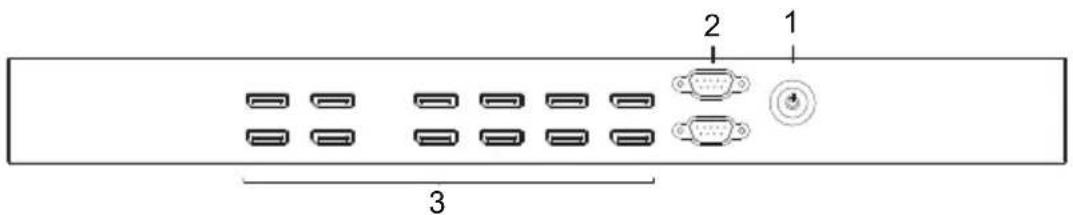
| No. | Component Description | |
| 1 Power | Button Press this | button to turn the VS1912 on / off. |
| 2 Bi-directional Serial ports | Connect a computer or high-end system controller via these serial ports. | |
| 3 Display | Port Output ports | The cables from the DisplayPort display devices plug into these ports. |
Rear View

| No. | Component Function | |
| 1 | Audio Output port The cable that connects to the audio input port on speakers plugs in here. | |
| 2 | USB 2.0 ports These ports are used for importing playback schedules from USB drives. | |
| 3 | USB 3.0 ports These ports are used for importing playback schedules from USB drives. | |
| 4 | LAN ports In order to upload media and access the VS1912's Browser Graphical User Interface (GUI), the VS1912 must be connected to a computer or network. The cable that connects the VS1912 to the LAN plugs in here. See Installation, page 7, for further details. DHCP (left), static IP (right). | |
| 5 | HDMI Input port The cable from the HDMI source device plugs in here. | |
| 6 | Power Socket This is a standard 3-pin AC power socket. The power cord from an AC source plugs in here. | |
| 7 | Power Switch This is a standard rocker switch that powers the unit on and off. | |
This Page Intentionally Left Blank
Chapter 2
Hardware Setup

- Important safety information regarding the placement of this device is provided on page 41. Please review it before proceeding.
- Make sure that the power to all devices connected to the installation are turned off.
- Make sure that all devices you will be installing are properly grounded.
Installation
Refer to the installation diagram on the following page (the numbers in the diagram correspond to the numbers of the steps) and do the following:
- Connect a computer to one of the VS1912's two Ethernet ports for configuring settings and uploading media files to the VS1912's internal storage.
- To begin the initial setup, it’s recommended that you connect the computer directly to the VS1912’s static (right) LAN port for a immediate access.
- The computer can be disconnected once the setup and file transfer are complete.
- For more information, please see Logging in, page 9.
Note: The left LAN port makes use of DHCP while the right uses a static IP address (192.168.100.1) and netmask (255.255.255.0).
-
Connect up to 12 DisplayPort display devices directly to any of the DisplayPorts on the front of the VS1912.
-
(Optional) Connect speakers to the Audio output port.
-
(Optional) If you are using the serial control function, use an appropriate RS-232 serial cable to connect the computer or serial controller to the VS1912's bi-directional RS-232 Serial ports. The end connecting to the
VS1912 should have a 9-pin male connector. See RS-232 Commands, page 39, for further details.
- (Optional) Connect a USB drive to any of the USB ports for importing playback schedules.
- (Optional) Connect an HDMI video source to the HDMI input port.
- Plug the power cord supplied with the package into the VS1912's 3-prong AC socket, and then connect this to an AC power source.
- Turn on access to the power source.
- First power on all display devices in the installation.
- Then power on the VS1912 and all other devices in the installation.
Installation Diagram

Overview
The VS1912 can be configured over a standard TCP/IP connection via its graphical user interface (GUI) using a web browser, or via a RS-232 serial controller. Media for playback can also be transferred to the VS1912's internal storage via a TCP/IP connection.
Logging in
To access the Browser GUI:
- Connect the VS1912 directly to your computer or to the network your computer is connected to (see page 7 for details).
-
Type the VS1912's IP address into the address bar of a web browser.
-
The VS1912's static (right) LAN port's default IP address is 192.168.100.1. To access it from a computer, ensure that the computer's IP address is 192.168.100.x (2 - 255) and that it shares the same network mask (255.255.255.0).
- If making use of the left LAN (DHCP) port, power on the VS1912 and confirm its IP via a connected display.
Note: 1. For best functionality, please use Google Chrome.
-
If a Security Alert dialog box appears, accept the certificate – it can be trusted.
-
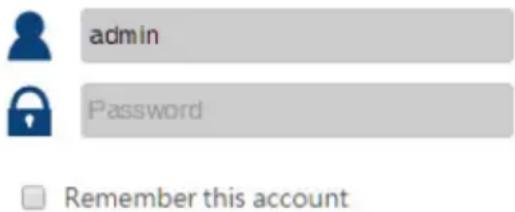
The welcome screen appears.
◆ The default Username and Password are: admin / admin
This Page Intentionally Left Blank
Overview
The VS1912 can be configured over a standard TCP/IP connection via its built-in Graphical User Interface (GUI). Because it can be accessed from anywhere over a network or the Internet, operators can easily log in via web browser. Security is ensured by password protection and a user-configurable time-out.
Logging in
To access the GUI, type the VS1912's IP address into the address bar of the Google Chrome web browser. If a Security Alert dialog box appears, accept the certificate – it can be trusted. The login screen appears:

◆ The fixed IP address is http://192.168.100.1
- The default Username and Password are: admin / admin
- Enter the username and password, then click Login.
◆ Use the drop-down menu to select the GUI language.
Note: 1. The username supports lower case letters only.
- The same account cannot simultaneously log in from different computers.
If a user attempts to log in using a web browser besides Google Chrome, they will be presented with the following warning message.:

Note: When first using the VS1912, please start by setting the Layout (see page 28).
Main Page
This is where you access the various features and settings of the VS1912. The page is divided into three parts: Profile, Scheduling and Overview.
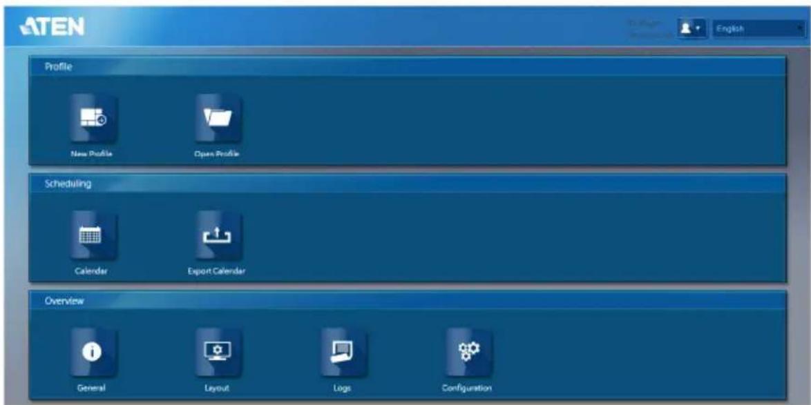
Menu Bar
The Menu Bar consists of two drop-down menus.

- User – click to access the log out button.
- Language Menu – click to select the language for the user interface.
- Options include: English, German, Spanish, Traditional Chinese, Simplified Chinese, Japanese and Korean.
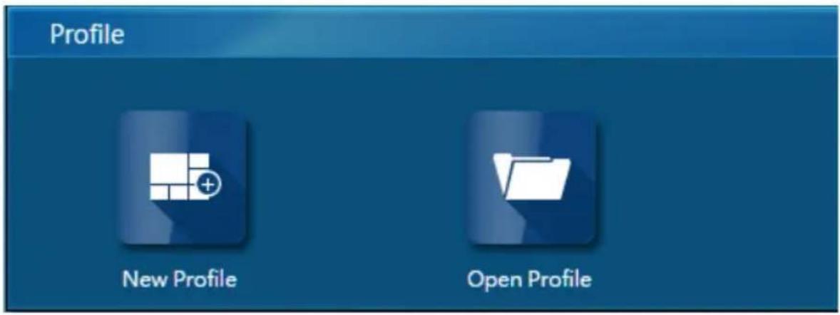
Profile
The Profile options allow you to set the video output via creating customized profiles. Before creating or playing a Profile, ensure that the displays' Layout has been correctly set up (see page 28). To play a Profile, see Playback, page 33.
Creating a Profile
To configure a new profile:
- From Profile, click on the [New Profile] icon.
- You will be presented with your display layout as a blank canvas:

bar
| X-Axis | Y-Axis | |---|---| | 500 | 100 | | 1000 | 200 | | 1500 | 300 | | 2000 | 400 | | 2500 | 500 | | 3000 | 600 | | 3500 | 700 | | 4000 | 800 |Note: To edit your display layout, please see Layout, page 28.
- To upload media files to the VS1912, click on the Upload button and select the desired files from the computer attached to the VS1912. For a list of supported file types, see page 44.
natural_image
Blue play button icon with a white triangle, displayed within a browser window (no text or symbols on the button itself)- Drag and drop media from the VS1912's internal storage onto the blank canvas.
![ATEN Home New Open Save Delete Scheduling Video 这里-有鱼音乐.avi big_buck_bunny_1080p_h To5-1920.mov 03.mp4 02.mp4 01.mp4 [播放拉的世界(阿凡拉IMAX 04.mp4 京维一号信天魔毒杀报告.avi] 500 1000 1500 2000 2500 3000 3500 4000](/content/2026/05/1142573/images/03354ceb399492c4d856db7ec508e79d7294d5ab7268fbed852dbb8e5edf87a2.jpg)
Note: 1. If you mouseover media files stored on the VS1912 (visible in the tree menu on the left), their thumbnails will appear in the top left-hand corner of the Profile screen.
-
For file playback limitations, see page 46.
-
Added media files can then be:
◆ Resized
natural_image
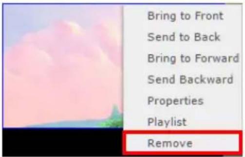
Illustration of a pink cloud over a hill with green trees in the foreground (no text or symbols)♦ Ordered (right-click on the media thumbnail on the canvas)

◆ Removed (right-click on the media thumbnail on the canvas)
- Use the Widget Bar to drag and drop widgets into the profile.
| Option Description | |
 | Use the Web Widget to include Internet content in the profile. For Web Widget limitation information, see page 47. |
 | Use the Text Widget to include text in the profile. |
 | Use the Text Banner Widget to include scrolling text in the profile. |
 | Use the Image Banner Widget to include a static (if only one) or scrolling (if multiple) images in the profile. |
 | Use the Analog Clock Widget to include a analog clock in the profile. |
 | Use the Digital Clock Widget to include a digital clock in the profile. |
 | Use the RSS Widget to include an RSS feed in the profile. |
 | Use the Streaming Widget to include streaming media in the profile. |
 | Use the Capture In Widget to play media from the HDMI input. |
Note: To customize each widget, once it has been included in your profile, right-click on the widget and select Properties.
- To save the profile, click on Save in the menu bar. Saving a profile will automatically publish it (see Playback, page 33, for player controls).

- To preview the current Profile, see Start Live View, Playback, page 33.
Opening a Profile
To open an existing profile:
- From Profile, click on the [Open Profile] icon.
- Select a profile from those available.

- Click Open Profile.
Deleting a Profile
To delete an existing profile:
- From Profile, click on the [Open Profile] icon.
- Select a profile from those available. Then click Open Profile.

- Next, select Delete from the menu bar.

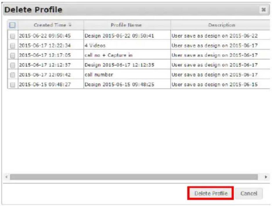
- Check the boxes next to the profiles you want to delete.
| Created Time | Profile Name | Description |
| 2015-06-22 09:50:45 | Design 2015-06-22 09:50:41 | User save as design on 2015-06-22 |
| 2015-06-17 12:22:34 | 4 Videos | User save as design on 2015-06-17 |
| 2015-06-17 12:17:05 | call no + Capture in | User save as design on 2015-06-17 |
| 2015-06-17 12:12:37 | Design 2015-06-17 12:12:35 | User save as design on 2015-06-17 |
| 2015-06-17 12:09:42 | call number | User save as design on 2015-06-17 |
| 2015-06-15 09:48:27 | Design 2015-06-15 09:48:25 | User save as design on 2015-06-15 |
5. Finally, click on Delete Profile.
Scheduling
Scheduling is located below the Profile options. Scheduling allows you to queue and play profiles in sequence for a specific amount of time.
Calendar
Clicking on the [Calendar] icon will display a profile schedule. The following options are available for browsing and viewing the [Calendar].
| Option Description | |
 | The Left button scrolls to the previous month/week/day. |
 | The Right button scrolls to the next month/week/day. |
 | The Today button returns you to the current month/week/day. |
 | The Month button displays the Calendar in monthly increments. |
 | The Week button displays the Calendar in weekly increments. It is the default view. |
 | The Day button displays the Calendar in daily increments. |
Adding Profiles to a Calendar
Saved profiles will be visible in the column to the left of the Calendar.
| Item |
| Design 2015-06-22 09:50:41 |
| 4 Videos |
| call no + Capture in |
| Design 2015-06-17 12:12:35 |
| call number |
| Design 2015-06-15 09:48:25 |
To add a profile to the Calendar:
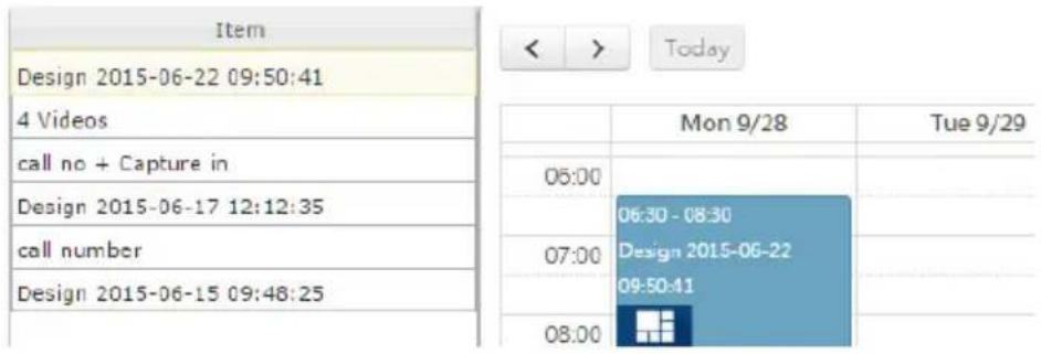
- Drag and drop the profile from the Profiles column into the desired time slot on the Calendar.
| Item | < > Today | ||
| Design 2015-06-22 09:50:41 | |||
| 4 Videos | Mon 9/28 | Tue 9/29 | |
| call no + Capture in | 06:00 | ||
| Design 2015-06-17 12:12:35 | Design 2015-06-22 09:50:41 | ||
| call number | 07:00 | ||
| Design 2015-06-15 09:48:25 | |||
| 08:00 | |||
- The profile will then become visible on the Calendar.
| Item | < | > | Today |
| Design 2015-06-22 09:50:41 | |||
| 4 Videos | |||
| call no + Capture in | 06:00 | ||
| Design 2015-06-17 12:12:35 | 06:30 - 08:30 | ||
| call number | 07:00 | Design 2015-06-22 | |
| Design 2015-06-15 09:48:25 | 09:50:41 | ||
| 08:00 |
To add more than one profile to a Calendar item (to create a Profile Sequence):
- Drag and drop a profile from the Profiles column into the desired time slot on the Calendar.

- Drag and drop another profile from the Profiles column into an already created Calendar item.

Editing Profiles in a Calendar
To edit a profile on the Calendar:
- Double-click on a profile that has been added to the Calendar.
- The profile's properties window will then appear.

- Here you can set the profile's:
◆ Duration: Start Time, End Time, All Day

♦ Repeat: Start Date, End Date

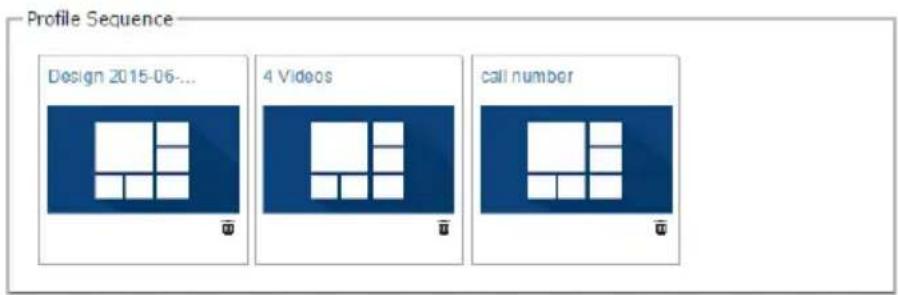
- Profile Sequence: The play order of profiles if more than one profile is included in the calendar item. Drag and drop the visible profiles into the Profile Sequence to add them. The duration of each individual profile will be the duration of the longest playing item within it.*
Note: To determine the duration of an item in a profile, right-click on said item, select Properties, and view the value labeled Media Duration (sec.).
- Once all settings are correct, click on Apply.

- If you want to remove the profile from the Calendar, click on Delete.

Saving a Calendar
To save the profile layout in your Calendar, click on the Save button in the top menu bar. Saving a profile will automatically publish it (see Playback, page 33, for player controls).

Clearing a Calendar
To clear the profile layout in your Calendar, click on the Clear button in the top menu bar.

Export Calendar
Clicking on the [Export Calendar] icon will download profile and calendar information to your computer's Download directory.
Importing Profile and Calendar Information
To import this information into a VS1912, copy the exported file to a USB drive and connect it to a USB port found on the device (see page 5 for details).
Note: Imported profile and calendar information will overwrite the existing profile and calendar information on the VS1912.
Overview
The Overview options allow you to view and configure the VS1912's settings.

General
Clicking on the [General] icon will display general system information. The following tabs are available in the [General] section:
- The System tab displays model, firmware version, schedule and profile information.

- The CPU/RAM Status tab displays the current CPU and memory usage.
| System | CPU/RAM Status | Network | Video Cards | Storage | |
| CPU/RAM Status | |||||
| CPU Usage | 33.3 % | ||||
| Total Memory | 7113MB | ||||
| Memory in Use | 5330MB | ||||
| Percentage of Memory In Use | 75 % | ||||
- The Network tab displays network information of the VS1912's two Ethernet ports (including DHCP status, IP address, MAC address, subnet mask and gateway information).
| Network | |||||
| LAN Port | DHCP | IP | MAC | Subnet Mask | Gateway |
| LAN1 | Off | 192.168.99.159 | 00:00:00:00:00:03 | 255.255.255.0 | |
| LAN2 | Off | 192.168.100.1 | 00:E0:4C:58:00:36 | 255.255.255.0 | |
- The Video Cards tab displays Layout, Video Card and Display information. To change Layout settings, see Layout, page 28.
| System | CPU/RAM Status | Network | Video Cards | Storage | |
| Layout | |||||
| Number of Columns | 2 | ||||
| Number of Rows | 4 | ||||
| Horizontal Basel | 200 px | ||||
| Vertical Basel | 0 px | ||||
| Max. Independent Screens | 9 | ||||
| Video Cards | |||||
| ID | Name | Ports | Enabled | ||
| 1 | E6760_HXM | 6 | 1 | ||
| 5 | 7660G | 3 | 1 | ||
| Displays | |||||
| ID | Orientation | Width | Height | ||
| 1 | 0^a | 1920 | 1080 | ||
| 2 | 0^a | 1920 | 1080 | ||
| 3 | 0^a | 1920 | 1080 | ||
| 4 | 0^a | 1920 | 1080 | ||
| 5 | 0^a | 1920 | 1080 | ||
| 6 | 0^a | 1920 | 1080 | ||
| 7 | 0^a | 1920 | 1080 | ||
| 8 | 0^a | 1920 | 1080 | ||
- The Storage tab displays Total, Available and Used storage available on the VS1912.
| System | CPU/SCAN Status | Network | Video Cards | Storage | |
| Storage | |||||
| Total | Available | Used | Percentage Used | ||
| 52GB | 41GB | 8.0GB | 18% | ||
Layout
Clicking on the [Layout] icon will allow users to set the display layout of the video wall. The following tabs are available in the [Layout] section: Standard Mode and Asymmetrical Mode. For details on supported display layouts, see page 44.
Standard Mode

In Standard Mode, the settings for a symmetrical video wall layout can be configured (see page 44 for supported symmetrical video wall layouts). The information and settings available include:
♦ Video Card Model(s): Displays the video card model number(s).
- Horizontal Bezel: Allows configuration of the horizontal bezel of the video wall. To enable editing, you must first click Show Bezel Bar. The users may then input the desired size (0-200 pixels) or use the on-screen slider.
- Vertical Bezel: Allows configuration of the vertical bezel of the video wall. To enable editing, you must first click Show Bezel Bar. The user may then input the desired size (0-200 pixels) or use the on-screen slider.
- Number of Columns: Allows the user to set the number of columns in the video wall.
- Number of Rows: Allows the user to set the number of rows in the video wall.
◆ Resolution: Allows the user to set the desired resolution of the video wall.
♦ Orientation: Allows the user to set the desired orientation of the video wall.
- EDID Override: Allows the user to override default EDID settings and customize the video wall’s refresh rate. If the video wall is operating normally, it is strongly suggested that the user does not enable EDID Override.
- Refresh Rate: If EDID Override is selected, the user may customize the video wall’s refresh rate.
- Show/Hide ID: Shows or hides each screen's ID number on the video wall.
- Show/Hide Bezel Bar: Shows or hides the bezel bar settings and on-screen slider.
- Apply: Once the user has selected your desired settings, click on Apply.
Asymmetrical Mode
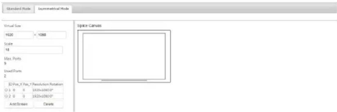
In Asymmetrical Mode, the settings for an asymmetrical (or non-standard) video wall layout can be configured. The information and settings available include:
- Virtual Size: Allows you to customize the screen’s resolution.
Scale: Allows you to resize the screen while maintaining its resolution.
Max. Ports: Displays the maximum ports available for the video wall.
◆ Used Ports: Displays the number of ports in use.
Screen List: Displays settings for each screen in the video wall. For details on editing these settings, see page 30. - Add Screen: If ports are available (see Max. Ports and Used Ports above), additional screens can be included in the video wall.
Note: In Asymmetrical Mode, the maximum number of screens is 8.
◆ Delete: To delete a screen, select it and click on Delete.
- Apply: Once you have selected your desired settings, click on Apply.
- Splice Canvas: Displays a virtual mockup of all screens in the video wall. By double-clicking on a screen in the Splice Canvas window or on a row in the Screen List, individual settings for the selected screen become available:

- Screen ID: The screen's identifying number (see Show/Hide ID, page 28, for details on how to show/hide screen ID numbers).
- Position X: The screen's position on the X axis. By default screens are at 0 on the X axis.
- Position Y: The screen's position on the Y axis. By default screens are at 0 on the Y axis.
♦ Resolution: The screen’s resolution. - Rotation: The screen's rotation. Options include 0^ , 90^ , 180^ and 270^ .
- Save: Saves the current screen settings.
◆ Delete: Removes the selected screen settings. - Apply: Saves and applies the current screen settings.
- Splice Canvas: Displays a virtual mockup of all screens in the video wall.
Logs
Clicking on the [Logs] icon will allow you to view and export system logs. Log types include: Playback, Information, Warning and Error. To enable system logging, set the maximum log file size and clear the log file, see Logs, page 37.
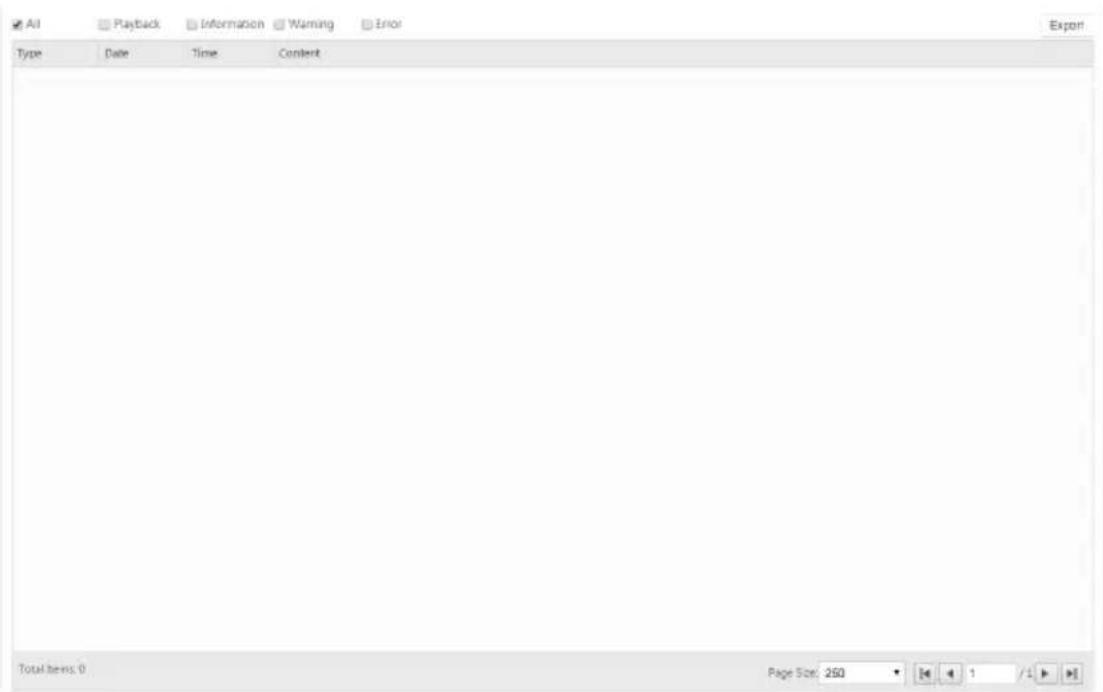
Exporting System Logs
To export the VS1912's system logs:
-
Click on the Export button in the top right-hand corner.
-
The system log will then be downloaded to the browser's download directory.
Configuration
Clicking on the [Configuration] icon will allow you to adjust important settings of the VS1912. The following tabs are available in the [Configuration] section: Power, Playback, Register Information, Server Information, Account, Network, Date/Time, Log and Firmware.
Power
The Power page allows you to configure the VS1912's Power Schedule as well as Reboot and Shutdown the unit.

To add an entry to the Power Schedule:
- Select the desired Action from the drop-down menu.

- Select the desired Frequency from the drop-down menu.

- Use the sliders to choose what time you want this task to occur at, then click Done.

- Click Add.

To Edit or Remove an entry from the Power Schedule:
- Select the entry.
- Click on either Edit or Remove at the bottom of the Power page.

Playback
The Playback page allows you to control profile playback, enable widget transparency and preview the current profile.

The Operation section allows you to: Start, Stop or Restart playback of the current profile.
Operation
Start Player
Stop Player
Restart Player
To enable the widget transparency feature during playback, select the checkbox under Widget Transparency Settings. For more information on widgets, see page 16.
Transparency Settings
Enable Transparency
To preview the current profile:
- Select Start Live View.
Start Live View
- A still image of the current profile will appear every few seconds at the bottom of the Playback page.
Stop Live View

natural_image
Two-panel image: top shows a coastal landscape with a yellow bridge over water, bottom shows a colorful garden path with flowers and plants (no text or symbols)License
The License page allows you to register the VS1912 with ATEN, view and update its License Key and view and update its Name.

Server Information
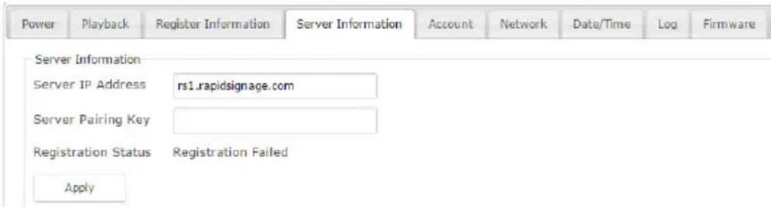
The Server Information page allows you to view and update the VS1912's Server IP Address, Server Pairing Key and confirm its Registration Status.
Account
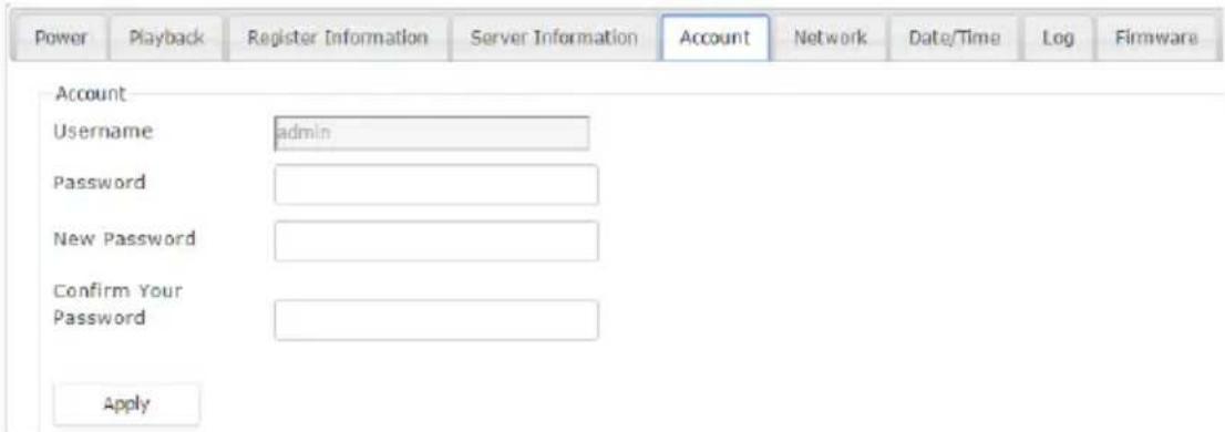
The Account page allows you to change the password used when accessing the VS1912's GUI.
Network
The Network page allows you to configure the VS1912's network settings.

In Network, double-click the DHCP, IP, Subnet Mask and Gateway fields to edit these settings. To set either of these two LAN ports as the Default Gateway, use the drop-down menu underneath this section.
Note: Check DHCP to allow the DHCP server to assign an IP address to the VS1912. Uncheck DHCP to enter your own static IP address settings for the device.
Domain Name Settings can be set up:
- Automatically by checking the Obtain DNS Settings Automatically option.
- Manually by entering one or two DNS server addresses in the fields at the bottom of this page.
To save your settings, click on Apply.
Date/Time
The Date/Time page allows you to configure the VS1912's internal clock and calendar.

This can be done:
- Manually by inputting the date and time.
- Automatically by selecting Sync with Computer. The VS1912 will then copy the date and time from the connected computer.
- Automatically by selecting Use Network Time. The VS1912 will then copy the date and time from the NTP server at the selected time interval.*
Note: This feature requires an active internet connection.
Logs
The Log page allows you to enable system logging, set the maximum log file size and clear the log file. To view or export the log file, see Logs, page 31.

Firmware
The Firmware allows you to view the VS1912's current firmware Version, update to newer firmware versions and Clear All Saved Data.

To upgrade the firmware, do the following:
- Click on the empty field to browse to the firmware upgrade file. Make sure you have the correct file for the VS1912.

natural_image
Simple red rectangular outline with a cloud icon in the bottom-right corner (no text or symbols)- Click on the upload button to start the upgrade process.

natural_image
Simple gray cloud icon inside a red square frame (no text or symbols)Note: 1. When updating firmware, it is recommended that users log in using an incognito window in Google Chrome ([Ctrl]+[Shift]+[N]). This ensures that no errors occur due to cookies.
- After updating the firmware, it's recommended that you clear your web browser's cache and then close and reopen the web browser. This will ensure the GUI refreshes and functions properly.
Overview
In order to use the RS-232 serial interface to attach a high-end controller (such as a PC) to the VS1912, use a serial cable such as a modem cable. The end connecting to the VS1912 should have a 9-pin male connector. Connect this to the serial interface on the rear of the VS1912. Refer to number 4 on the diagram on page 8.
Note: 1. RS-232 functionality is pending and will be available with future firmware upgrades.
- To configure the controller serial port, see the section below.
RS-232 Serial Interface
The VS1912's built-in bi-directional RS-232 serial interface allows system control through a high-end controller, PC, and/or home automation / home theater software package.
Configuring the Serial Port
The controller's serial port should be configured as follows:
| Baud Rate 19200 | |
| Data Bits 8 | |
| Parity None | |
| Stop Bits 1 | |
| Flow Control None | |
This Page Intentionally Left Blank
Safety Instructions
General
- Read all of these instructions. Save them for future reference.
◆ Follow all warnings and instructions marked on the device. - This product is for indoor use only.
- Do not place the device on any unstable surface (cart, stand, table, etc.). If the device falls, serious damage will result.
- Do not use the device near water.
- Do not place the device near, or over, radiators or heat registers.
- The device cabinet is provided with slots and openings to allow for adequate ventilation. To ensure reliable operation, and to protect against overheating, these openings must never be blocked or covered.
- The device should never be placed on a soft surface (bed, sofa, rug, etc.) as this will block its ventilation openings. Likewise, the device should not be placed in a built-in enclosure unless adequate ventilation has been provided.
- Never spill liquid of any kind on the device.
- Unplug the device from the wall outlet before cleaning. Do not use liquid or aerosol cleaners. Use a damp cloth for cleaning.
- The device should be operated from the type of power source indicated on the marking label. If you are not sure of the type of power available, consult your dealer or local power company.
- The device is designed for IT power distribution systems with 230V phase-to-phase voltage.
- To prevent damage to your installation it is important that all devices are properly grounded.
- To help protect your system from sudden, transient increases and decreases in electrical power, use a surge suppressor, line conditioner, or un-interruptible power supply (UPS).
-
Position system cables and power cables carefully; Be sure that nothing rests on any cables.
-
Never push objects of any kind into or through cabinet slots. They may touch dangerous voltage points or short out parts resulting in a risk of fire or electrical shock.
- Do not attempt to service the device yourself. Refer all servicing to qualified service personnel.
- If the following conditions occur, unplug the device from the wall outlet and bring it to qualified service personnel for repair.
◆ Liquid has been spilled into the device.
◆ The device has been exposed to rain or water.
- The device has been dropped, or the cabinet has been damaged.
- The device exhibits a distinct change in performance, indicating a need for service.
- The device does not operate normally when the operating instructions are followed.
- Only adjust those controls that are covered in the operating instructions. Improper adjustment of other controls may result in damage that will require extensive work by a qualified technician to repair.
Technical Support
International
- For online technical support – including troubleshooting, documentation, and software updates: http://eservice.aten.com
◆ For telephone support, see Telephone Support, page iv:
North America
| Email Support support@aten-usa.com | ||
| Online Technical Support | Troubleshooting Documentation Software Updates | http://www.aten-usa.com/support |
| Telephone Support 1-888-999-ATEN | ext 4988 | |
When you contact us, please have the following information ready beforehand:
◆ Product model number, serial number, and date of purchase.
- Your computer configuration, including operating system, revision level, expansion cards, and software.
◆ Any error messages displayed at the time the error occurred.
◆ The sequence of operations that led up to the error.
◆ Any other information you feel may be of help.
Supported Display Layouts
Orientation
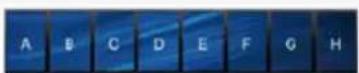
The following video wall display layouts are supported by the VS1912:
| Layout Orientation Resolution | ||
| 8x1 Landscape / Portrait 1920x1080 / 1080x1920 | ||
| 6x2 | ||
| 4x3 | ||
| 3x4 | ||
| 2x6 | ||
| 1x8 | ||

4x3 Landscape

3x4 Landscape

3x3 Landscape

2x4 Landscape
8x1 Portrait

8x1 Landscape

2x4Portrait
Rotation
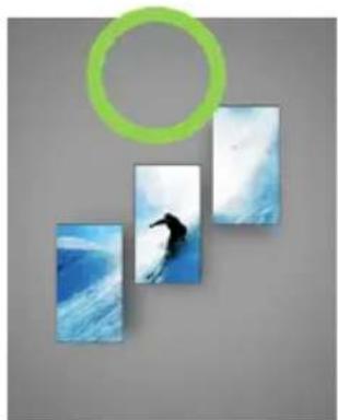
Only screen rotations of 0^ , 90^ , 180^ and 270^ are supported:
natural_image
Three blue-and-white photo panels with a black silhouette of a seahorse, one outlined in green (no text or symbols)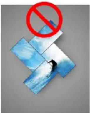

natural_image
Silhouette of a person surfing on a blue wave against a cloudy sky, with a green circular overlay (no text or symbols)Supported File Types
The following file types are supported during upload and playback operations:
| Media Type Format | ||||||
| Video mp4 | avi wmv mov | m4v mkv | ||||
| Flash swf | ||||||
| Audio mp3 | mp2 m4a m1a wav | |||||
| Image (Static) | jpg jpeg bmp png | |||||
| Image (Animated) | gif | |||||
| Document (Office) | ppt pptx doc docx xls xlsx | |||||
| Document (Other) | ||||||
| Web htm html | ||||||
Playback Limitations
When using audio, video and web widgets in a profile, specific limitations exist.
Audio
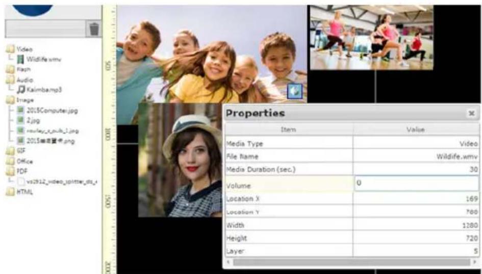
If a profile includes several audio files or videos with sound, then the audio output will feature these mixed together. To avoid this, please turn the volume off on select video and audio files manually.
To do this, follow these steps:
- Right-click on the file in the profile canvas.
- Click on Properties.

- Change the value for Volume to 0.
Video
When using more than one screen and playing of more than one video, the following limitations apply (please note that these values are for reference only):
| Mode | Video Wall Screens | Max. Resolution | Video Files | Max. Bit Rate |
| Standard 12 1 | 920x1080/1080P 2 32 | |||
| 12 1920x1080/1080P 4 8 | ||||
| 4 1920x1080/1080P 4 32 | ||||
| Asymmetrical | 8 1280x720/720P 1 32 | |||
| 4 1280x720/720P 2 32 |
Web Widget
If a web widget is created with a resolution over 2048X2048, then it must be contained within one screen. If such a widget overlaps two or more screens, the following warning message will appear:

Specifications
| Function VS1912 | ||
| Video Input Interface 1 x HDMI Type A Female | ||
| Video Output Interface 12 x DisplayPort 1.1 Female | ||
| Video Max. Data Rate 8.64 Gbps (2.7 Gbps per lane) | ||
| Max. Pixel Clock 340 MHz (with DP to DVI active adapter) | ||
| Compliance HDMI (3D, Deep Color) DisplayPort 1.1 | ||
| Audio Output 1 x 3.5 mm Stereo Jack Female | ||
| Control RS-232* Connector: 2 x DB-9 Female (Black) Baud Rate: 38400–19200 Protocol: Hardware & Software Flow Control | ||
| Ethernet 2 x RJ-45 Female | ||
| USB | 2 x USB 3.0 Female4 x USB 2.0 Female | |
| Power | Connector | 1 x 3-Prong AC Socket |
| I/P Rating | 100-240 VAC; 50-60 Hz; 3.0 A | |
| Consumption | 120 VAC, 400W; 230 VAC, 400W | |
| Environment | Operating Temp. | 0–40°C |
| Storage Temp. | -20–60°C | |
| Humidity | 0–80% RH, Non-condensing | |
| Physical Properties | Housing | Metal |
| Weight | 5.75 kg (Chassis Only) | |
| Dimensions (L x W x H) | 43.00 x 27.00 x 4.40 cm | |
| Carton Lot | 3 pcs | |
* RS-232 functionality is pending and will be available with future firmware upgrades.
This Page Intentionally Left Blank
Limited Warranty
IN NO EVENT SHALL THE DIRECT VENDOR'S LIABILITY EXCEED THE PRICE PAID FOR THE PRODUCT FROM DIRECT, INDIRECT, SPECIAL, INCIDENTAL, OR CONSEQUENTIAL DAMAGES RESULTING FROM THE USE OF THE PRODUCT, DISK, OR ITS DOCUMENTATION.
The direct vendor makes no warranty or representation, expressed, implied, or statutory with respect to the contents or use of this documentation, and especially disclaims its quality, performance, merchantability, or fitness for any particular purpose.
The direct vendor also reserves the right to revise or update the device or documentation without obligation to notify any individual or entity of such revisions, or update. For further inquiries, please contact your direct vendor.



- 12-Port DP Video Wall Media Player
- VS1912
- User Manual
- FCC Information
- FEDERAL COMMUNICATIONS COMMISSION INTERFERENCE
- KCC Statement
- Safety
- SJ/T 11364-2006
- Telephone Support
- User Notice
- Package Contents
- Contents
- Chapter 1.
- Introduction
- Chapter 2.
- Hardware Setup
- Chapter 3.
- Basic Operation
- Chapter 4.
- Browser Operation
- Chapter 5.
- RS-232 Commands
- Appendix
- About this Manual
- Conventions
- Product Information
- Overview
- Features
- Requirements
- Source Device
- Receiving Device
- Cables
- Components
- Front View
- Rear View
- Chapter 2
- Installation
- Logging in
- Main Page
- Menu Bar
- Profile
- Creating a Profile
- Opening a Profile
- Deleting a Profile
- Finally, click on Delete Profile.
- Scheduling
- Calendar
- Adding Profiles to a Calendar
- Editing Profiles in a Calendar
- Saving a Calendar
- Clearing a Calendar
- Export Calendar
- Importing Profile and Calendar Information
- General
- Layout
- Standard Mode
- Asymmetrical Mode
- Logs
- Exporting System Logs
- Configuration
- Power
- Playback
- Operation
- License
- Server Information
- Account
- Network
- Date/Time
- Firmware
- RS-232 Serial Interface
- Configuring the Serial Port
- Safety Instructions
- Technical Support
- International
- Supported Display Layouts
- Orientation
- Rotation
- Supported File Types
- Playback Limitations
- Audio
- Video
- Web Widget
- Limited Warranty
Brand : ATEN
Model : VS1912
Category : Video switch