OL8000E - UPS CyberPower - Free user manual and instructions
Find the device manual for free OL8000E CyberPower in PDF.

User questions about OL8000E CyberPower
0 question about this device. Answer the ones you know or ask your own.
Ask a new question about this device
Download the instructions for your UPS in PDF format for free! Find your manual OL8000E - CyberPower and take your electronic device back in hand. On this page are published all the documents necessary for the use of your device. OL8000E by CyberPower.
USER MANUAL OL8000E CyberPower
Reliability. Quality. Value.
User's Manual
OL6000ERT3UD
OL8000ERT3UD
OL10000ERT3UD
CyberPower Systems Inc.
www.cpsww.com
K01-0000220-00
This manual contains important instructions. Please read and follow all instructions carefully during installation and operation of the unit. Read this manual thoroughly before attempting to unpack, install, or operate the UPS.
CAUTION! The UPS must be connected to a grounded AC power outlet with fuse or circuit breaker protection. DO NOT plug the UPS into an outlet that is not grounded. If you need to power-drain this equipment, turn off and unplug the unit.
CAUTION! The battery can power hazardous components inside the unit, even when the AC input power is disconnected.
CAUTION! The UPS should be placed near the connected equipment and easily accessible.
CAUTION! To prevent the risk of fire or electric shock, install in a temperature and humidity controlled indoor area, free of conductive contaminants. (Please see specifications for acceptable temperature and humidity range).
CAUTION! (No User Serviceable Parts): Risk of electric shock, do not remove cover. No user serviceable parts inside. Refer servicing to qualified service personnel.
CAUTION! (Non-Isolated Battery Supply): Risk of electric shock, battery circuit is not isolated from AC power source; hazardous voltage may exist between battery terminals and ground. Test before touching.
CAUTION! To reduce the risk of fire, connect the UPS to a branch circuit with 40 amperes (OL6000) / 50 amperes (OL8000) / 60 amperes (OL10000) maximum over-current protection in accordance to CE requirement.
CAUTION! The AC outlet where the UPS is connected should be close to the unit and easily accessible.
CAUTION! Please use only VDE-tested, CE-marked mains cable, (e.g. the mains cable of your equipment), to connect the UPS to the AC outlet.
CAUTION! Please use only VDE-tested, CE-marked power cables to connect any equipment to the UPS.
CAUTION! When installing the equipment, ensure that the sum of the leakage current of the UPS and the connected equipment does not exceed 3.5mA.
CAUTION! The OL6000 / OL8000 / OL10000 models are permanently-connected equipment and only qualified maintenance personnel may carry out installations.
CAUTION! Do not unplug the unit from AC Power during operation, as this will invalidate the protective ground insulation.
CAUTION! To avoid electric shock, turn off and unplug the unit before installing the input/output power cord with a ground wire. Connect the ground wire prior to connecting the line wires!
CAUTION! Do not use an improper size power cord as it may cause damage to your equipment and cause fire hazards.
CAUTION! Wiring must be done by qualified personnel.
CAUTION! DO NOT USE FOR MEDICAL OR LIFE SUPPORT EQUIPMENT! Under no circumstances this unit should be used for medical applications involving life support equipment and/or patient care.
CAUTION! DO NOT USE WITH OR NEAR AQUARIUMS! To reduce the risk of fire, do not use with or near aquariums. Condensation from the aquarium can come in contact with metal electrical contacts and cause the machine to short out.
CAUTION! Do not dispose of batteries in fire as the battery may explode.
CAUTION! Do not open or mutilate the battery, released electrolyte is harmful to the skin and eyes.
CAUTION! A battery can present a risk of electric shock and high short circuit current. The following precaution should be observed when working on batteries
-
Remove watches, rings or other metal objects.
-
Use tools with insulated handles.
CAUTION! The unit has a dangerous amount of voltage. When the UPS indicators is on, the units may continue to supply power thus the unit's outlets may have a dangerous amount of voltage even when it's not plugged in to the wall outlet.
CAUTION! Make sure everything is turned off and disconnected completely before conducting any maintenance, repairs or shipment.
CAUTION! Connect the Protection Earth (PE) safety conductor before any other cables are connected.
WARNING! (Fuses): To reduce the risk of fire, replace only with the same type and rating of fuse.
DO NOT INSTALL THE UPS WHERE IT WOULD BE EXPOSED TO DIRECT SUNLIGHT OR NEAR A STRONG HEAT SOURCE!
DO NOT CONNECT DOMESTIC APPLIANCES SUCH AS HAIR DRYERS TO UPS OUTPUT SOCKETS!
SERVICING OF BATTERIES SHOULD BE PERFORMED OR SUPERVISED BY PERSONNEL KNOWLEDGE OF BATTERIES AND THE REQUIRED PRECAUTIONS. KEEP UNAUTHORIZED PERSONNEL AWAY FROM BATTERIES!
UNPACKING
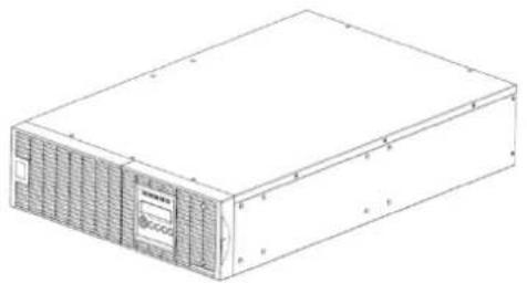
natural_image
Line drawing of a rectangular electronic device with ventilation grilles and a label on the front panel (no readable text or symbols)Power module

natural_image
Line drawing of a rectangular metal enclosure with mounting holes and internal compartments (no text or symbols)Input / Output terminal block cover

User's manual

Register card

natural_image
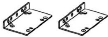
Pure technical line drawing of a mechanical bracket or support structure without any text, numbers, or symbolsRackmount left rail * 2 sets
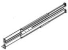
Rackmount right rail * 2 sets
Phone line
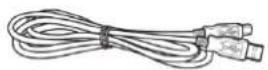
USB communication cable

Serial Interface Cable (RS-232)

natural_image
Isometric line drawing of a rectangular electronic device with ventilation grilles (no text or symbols)Battery module
natural_image
Two identical 3D metal bracket diagrams with mounting holes and mounting holes (no text or symbols)Rackmount ears (Stands) (2) * 2 sets
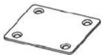
Tie plate (1) * 2 sets

Flat head screws: M5X8L (8) * 2 sets

Pan head screws: M5X12L (12) * 2 sets

Plastic washers (8) * 2 sets

Screw hole dust covers (10) * 2 sets
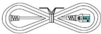
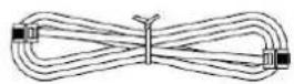
natural_image
Pure diagram of a mechanical or electrical component with no text, numbers, or symbolsPower cords

PowerPanel® Business Edition software CD
HARDWARE INSTALLATION
These versatile UPS systems can be mounted in a rackmount or vertical tower orientation. This versatility is especially important to growing organizations with changing needs that value having the option to position a UPS on a floor or in a rackmount system. Please follow the instructions below for the respective mounting methods.
SAFETY PRECAUTIONS
CAUTION! To prevent the risk of fire or electric shock, only use the supplied hardware to attach the mounting brackets.
RACKMOUNT INSTALLATION
Step 1: Remove the internal battery trays from the Battery module (See page 16)
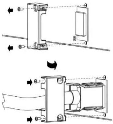
Step 2: Rackmount ears installation
Attach the two rackmount ears to the Battery module using the provided screws M5X8L*8pcs.

text_image
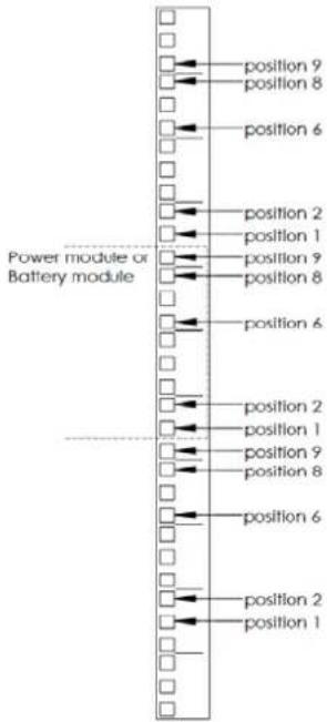
Technical diagram of a server rack with labeled components and ventilation grillesStep 3: Rackmount rail Installation
The rails adjust to mount in 48-cm (19-inch) panel racks from 52 to 91.5cm (20.5 to 36 inches) deep. Select the proper holes in the rack for positioning the Battery module in the rack. The Power module or the Battery module takes up position 1 through position 9.
text_image
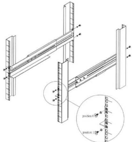
position 9 position 8 position 6 position 2 position 1 position 9 position 8 position 6 position 2 position 1 position 9 position 8 position 6 position 2 position 1 position 9 position 8 position 6 position 2 position 1Step 4: Adjust rackmount rails to fit your rack
Attach the rackmount rail to your rack with two M5X12L screws and two plastic washers at the front of the rack. (Located in position 1 & position 6) Do not tighten the screws. Adjust the rail size on the rail assembly of your rack. Secure the rail to the rear of the rack with two M5X12L screws and two plastic washers. Tighten all screws at the front and rear of the rail. Once completed, perform the same steps for assembling the other rackmount rail.
text_image
Technical diagram of a structural frame assembly with labeled positions and connection pointsPlace the Battery module on a flat stable surface with the front of the unit facing toward you. Secure the Battery module to your rack with four M5X12L screws at the front of the rack. (Located in position 2 & position 8)

text_image
position 6 position 1 position 2Step 5: Place the internal battery trays back into the Battery module (See page 16)
Once completed, perform the same steps for the Power module.
CAUTION! The Battery module must be installed below the Power module.
VERTICAL/TOWER INSTALLATION
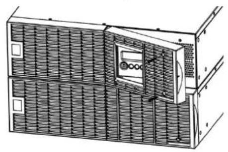
Step 1: Rotate the Multifunction LCD Module
Unscrew the right panel of the Power module. Separate the right panel from the UPS. Gently lift the LCD module out. Rotate it to the tower orientation. Reinstall it for a tower configuration.
natural_image
Architectural diagram of a two-story building facade with ventilation grilles and a central control unit (no text or symbols)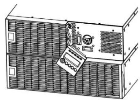
natural_image
Diagram of a server rack with a computer monitor and ventilation unit (no text or symbols)
natural_image
Architectural elevation drawing of a building facade with tiled roof and window (no text or symbols)Step 2: Attach the base stands
Secure the tie bracket with the screws (M5X8*4pcs). Tighten the screws (M5X12*4pcs) of the base stands (rackmount ears) onto the bottom of the power module and the battery module.

natural_image
Technical line drawing of a server rack unit with ventilation grilles and control panel (no text or symbols)Step 3: Attach dust covers
Insert dust covers into the rackmount ear screw holes that are not being used.
ELECTRICAL INSTALLATION
After completing the hardware installation of the UPS, you are now ready to plug in the UPS and connect your equipment.
SAFETY PRECAUTIONS
CAUTION! Installation environment should be in a temperature and humidity controlled indoor area free of conductive contaminants. Do not install this UPS where excessive moisture or heat is present (Please see specifications for acceptable temperature and humidity range).
CAUTION! Never install a UPS, or associated wiring or equipment, during a lightning storm.
CAUTION! Do not work alone under hazardous conditions.
CAUTION! In case of the risk of electric shock, do not remove the top cover.
CAUTION! The battery can energize hazardous live parts inside even when the AC input power is disconnected.
SYSTEM BLOCK DIAGRAM
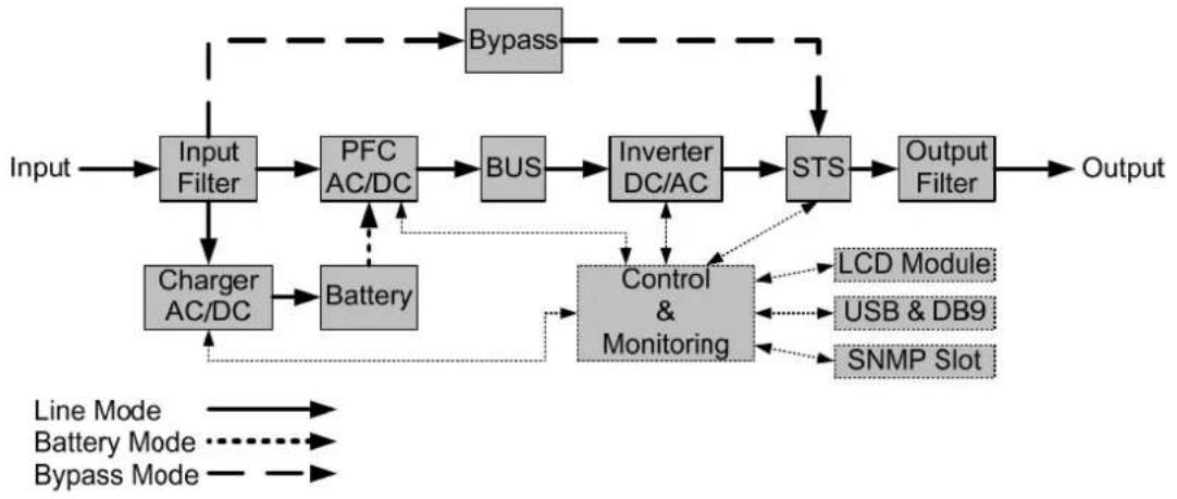
flowchart
graph TD
    A["Input"] --> B["Input Filter"]
    B --> C["PFC AC/DC"]
    C --> D["BUS"]
    D --> E["Inverter DC/AC"]
    E --> F["STS"]
    F --> G["Output Filter"]
    G --> H["Output"]
    I["Line Mode"] --> J["Battery Mode"]
    J --> K["Battery"]
    L["Bypass Mode"] --> M["Bypass"]
    M --> N["Bypass"]
    O["Charger AC/DC"] --> P["Battery"]
    P --> Q["Control & Monitoring"]
    Q --> R["LCD Module"]
    Q --> S["USB & DB9"]
    Q --> T["SNMP Slot"]
HARDWARE INSTALLATION GUIDE
- Battery charge loss may occur during shipping and storage. Before using the UPS, it's strongly recommended to charge batteries for four hours to ensure the batteries' maximum charge capacity. To recharge the batteries, simply plug the UPS into an AC outlet.
- When using the included software, connect either the serial or the USB cable between the computer and the corresponding port on the UPS. Note: If the USB port is used, the serial port will be disabled. They cannot be used simultaneously. After connecting to either the USB port or the Serial port on the UPS, a computer with the PowerPanel® Business Edition Agent software installed can control the operating schedule, battery test, outlets, as well as obtain UPS status information. However, other computers with PowerPanel® Business Edition Client software can only obtain UPS status information via LAN connection.
- Connect your computer, monitor, and any externally-powered data storage device (Hard drive, Tape drive, etc.) into the outlets only when the UPS is off and unplugged. DO NOT plug a laser printer, copier, space heater, vacuum, paper shredder or other large electrical device into the UPS. The power demands of these devices will overload and possibly damage the unit.
- To protect a fax machine, telephone, modem line or network cable, connect the telephone or network cable from the wall jack outlet to the jack marked "IN" on the UPS and connect a telephone cable or network cable from the jack marked "OUT" on the UPS to the modem, computer, telephone, fax machine, or network device.
-
Press the ON/OFF switch to turn the UPS on. The Power-On indicator light will display when activated. If an overload is detected, an audible alarm will sound and the UPS will continuously emit two beeps per second. For resetting the unit, unplug some equipment from the outlets. Make sure your equipment carries a load current within the unit's safe range, (refer to the technical specifications).
-
This UPS is equipped with an auto-charge feature. When the UPS is plugged into an AC outlet, the battery will automatically charge, even when the unit is switched off.
- To maintain an optimal battery charge, leave the UPS plugged into an AC outlet at all times.
- Before storing the UPS for an extended period of time, turn the unit OFF. Then cover it and store it with the batteries fully charged. Recharge the batteries every three months to ensure good battery capacity and long battery life. Maintaining a good battery charge will help prevent possible damage to the unit from battery leakage.
- The UPS has one USB port (default) and one Serial port that allows connection and communication between the UPS and any attached computer running the PowerPoint® Business Edition Agent software. The UPS can control the computer's shutdown during a power outage through the connection while the computer can monitor the UPS and alter various programmable parameters. Note: Only one communication port can be used at a time. The port not in use will automatically become disabled or the serial port will be disabled if both ports are attached.
- EPO (Emergency Power Off) Port: EPO ports allow administrators the capability to connect the UPS unit to customer-supplied EPO switches. These installations give operators a single access point to immediately power-off all equipment connected to the UPS during an emergency.
- To avoid electric shock, turn the unit OFF and disconnect the unit from utility power before hardwiring the UPS (in/out power cord). The in/out power cord MUST be grounded.
CHECK CIRCUIT BREAKER/WIRING
Check branch circuit breaker rating and wiring dimensions with the following table.
| UPS Capacity | Branch Circuit Breaker | Wiring AWG | Wiring mm^2 |
| 6KVA 40A | 10 AWG 5.5 mm | ^2 | |
| 8KVA 50A | 8 AWG 8.0 mm | ^2 | |
| 10KVA 60A | 6 AWG 14.0 mm | ^2 |
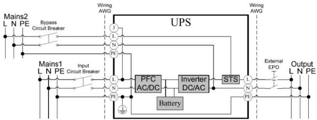
Hardwire the input/output terminals as shown in the following diagram.

flowchart
graph TD
    A["Mains L N PE"] --> B["Input Circuit Breaker"]
    B --> C["J"]
    C --> D["L"]
    D --> E["N"]
    E --> F["PE"]
    F --> G["PFC AC/DC"]
    G --> H["Inverter DC/AC"]
    H --> I["STS"]
    I --> J["L N PE"]
    J --> K["External EPO"]
    K --> L["Output L N PE"]
    M["Wiring AWG"] --> N["UPS"]
    O["Wiring AWG"] --> N
    P["Battery"] --> G
    Q["Jumper"] --> C
- Remove the interconnection wires (Jumper) on bypass terminals.
- Hardwire the input/output terminals as shown in the following diagram.
flowchart
graph TD
    A["Mains1 L N PE"] --> B["Input Circuit Breaker"]
    C["Wiring AWG"] --> D["UPS"]
    E["Bypass Circuit Breaker"] --> F["Input Circuit Breaker"]
    G["Wiring AWG"] --> H["UPS"]
    I["PFC AC/DC"] --> J["Inverter DC/AC"]
    K["Battery"] --> L["PS"]
    M["STS"] --> N["External EPO"]
    O["Output L N PE"] --> P["Output L N PE"]
SAFETY PRECAUTIONS
CAUTION! Input and Output circuit breakers must be "OFF" during the building installation.
CAUTION! An additional two pole disconnect device is necessary during the building installation.
CAUTION! Disconnected EPO will immediately shut down the logic circuit output of the UPS. Wiring the EPO signal is optional.
CAUTION! Local safety rules may require a separate, external EPO to turn off output circuit breakers. Refer to local wiring rules, the EPO should use approved components.
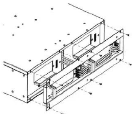
HARDWIRING THE INPUT/ OUTPUT TERMINALS
Step 1: Separate the top and bottom covers
Loosen the four screws to separate the top and bottom covers.
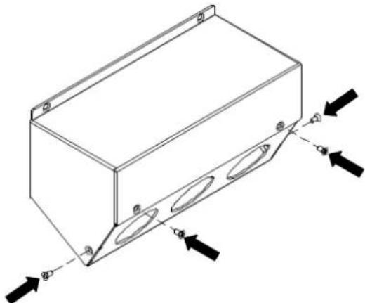
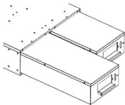
natural_image
Isometric line drawing of a rectangular box with internal oval cutouts and directional arrows indicating force or movement (no text or symbols)Step 2: Fix the bottom cover on the terminal block
Tighten the two screws to fix the bottom cover on the terminal block.

text_image
Technical diagram of an electronic device with labeled components and directional arrows indicating movement or assembly.Step 3: Bypass configuration (for dual input configuration)
Remove the interconnection wires (Jumper) on bypass terminals (J / L) and insert the bypass cable through the appropriate cable gland (not included).
text_image
Technical diagram of a mechanical or electrical component with labeled parts and directional indicatorsConnect the three wires to the bypass terminal block (L / N / G).

text_image
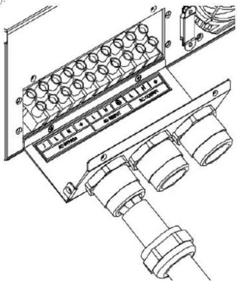
AC BYPASS AC INPUT AC OUTPUTStep 4: Input configuration
Insert the input cable through the appropriate cable gland (not included).

natural_image
Technical line drawing of an electrical enclosure with cylindrical components and wiring (no text or symbols)HARDWIRING THE INPUT/ OUTPUT TERMINALS
Connect the three wires to the input terminal block.

natural_image
Technical line drawing of an electrical enclosure with coiled pipes and labeled components (no readable text or symbols)Step 5: Output configuration
Insert the output cable through the appropriate cable gland (not included)

natural_image
Technical line drawing of an electrical connector assembly (no text or symbols)Connect the three wires to the output terminal block.

natural_image
Technical line drawing of an electrical connector assembly with multiple cylindrical components and wiring (no text or symbols)Step 6: Fix the top cover on the bottom cover
Tighten the six screws to fix the top cover on the bottom cover.

natural_image
Technical line drawing of a mechanical assembly with rollers and directional arrows (no text or symbols)- If the Bypass circuit is shorted and the UPS is running in Line Mode or Battery Mode, backfeed protection will be active and the external isolation device (Magnetic Contactor) will open.
- Save your data and perform a controlled shutdown.
- Contact CyberPower for repair.
WITHOUT BACKFEED PROTECTION CONFIGURATION
- Hardwire the input terminals as shown in the following diagram.
- Do not remove the interconnection wires (Jumper1 / Jumper2) on "Backfeed Protection Connector".

flowchart
graph TD
    A["Mains L N PE"] --> B["L"]
    A --> C["N"]
    A --> D["PE"]
    B --> E["I/P EMI"]
    C --> E
    D --> E
    E --> F["IP-L"]
    E --> G["IP-N"]
    H["PSDR"] --> I["Backfeed"]
    I --> J["AC-L"]
    I --> K["AC-N"]
    L["Jumper1"] --> I
    M["Jumper2"] --> I
    I --> N["1"]
    I --> O["2"]
    I --> P["3"]
    I --> Q["4"]
    I --> R["5"]
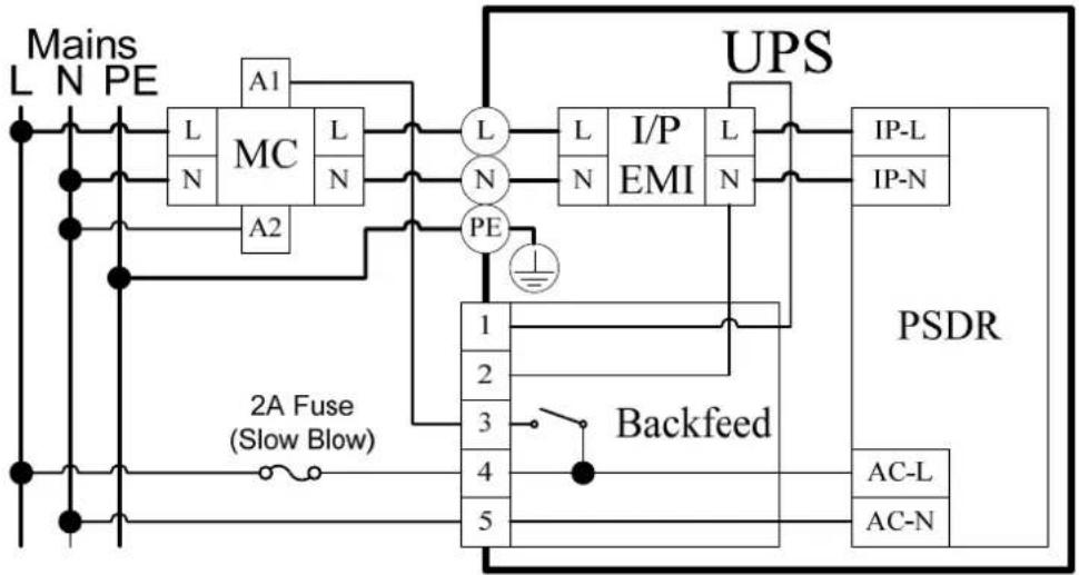
WITH BACKFEED PROTECTION CONFIGURATION
- Customers should provide an external isolation device (Magnetic Contactor) which is upstream and outside the UPS and capable of supporting the UPS input current.
- Remove the interconnection wires (Jumper1 / Jumper2) on "Backfeed Protection Connector".
- Hardwire the input terminals and "Backfeed Protection Connector" as shown in the following diagram.
- The external isolation device must be installed in the Mains path.
flowchart
graph TD
    A["Mains L"] --> B["MC"]
    C["N"] --> B
    D["PE"] --> B
    B --> E["L"]
    B --> F["N"]
    B --> G["L"]
    H["A1"] --> I["UPS"]
    I --> J["I/P EMI"]
    I --> K["L"]
    I --> L["N"]
    M["A2"] --> N["PE"]
    N --> O["1"]
    N --> P["2"]
    N --> Q["3"]
    R["PSDR"] --> S["Backfeed"]
    T["AC-L"] --> U["5"]
    V["AC-N"] --> W["5"]
    X["2A Fuse (Slow Blow)"] --> Y["Ground"]
    Z["Ground"] --> AA["Ground"]
POWER MODULE FRONT/REAR PANEL DESCRIPTION
1. Power Button / Power on Indicator
Master ON/OFF for the UPS. Indicates that the UPS is on and supplying power.
2. UPS Status / Fault / Replace Battery LED Indicator
Indicates the status of the UPS whether is operating in Line, Battery or Bypass Mode, or the UPS has an internal fault and the battery need to be replaced.
3. Multifunction LCD Readout
Shows UPS status, information, settings and events.
4. Function Buttons
Scroll up, scroll down, select and cancel LCD menu.
5. Input Circuit Breaker
Provides input overload and fault protection.
6. Input / Output Terminal Block
Connect to utility power / your equipment.
7. Output Circuit Breaker
Provides output overload and fault protection.
8. Battery Backup & Surge Protected Outlets
Provides battery backup and surge protection. They ensure power is provided to connected equipment over a period of time during a power failure.
Critical / Noncritical Load
Allows the creation of load priorities to ensure that battery power reserves are transferred to specified outlets during a power outage. The unit can be programmed to provide additional runtime for equipment connected to the "CRITICAL" outlets, while stopping the power supply to equipment connected to "NONCRITICAL" outlets after a designated period of time.
9. Serial Port
Serial port provides communication between the UPS and the computer. The UPS can control the computer's shutdown during a power outage through the connection while the computer can monitor the UPS and alter its various programmable parameters.
10. USB port
This is a connectivity port which allows communication and control between the UPS and the connected computer. It is recommended to install the PowerPanel® Business Edition Agent software on the PC/Server connected with the USB cord.
11. Remote Control Port
Connects to remote LCD module to the UPS.
12. Surge Protected Communication Ports RJ-45/RJ-11
These ports are used to protect standard RJ-45/RJ-11 based products (ADSL, LAN, Phone/ Modem-Lines) and cabling systems from surges.
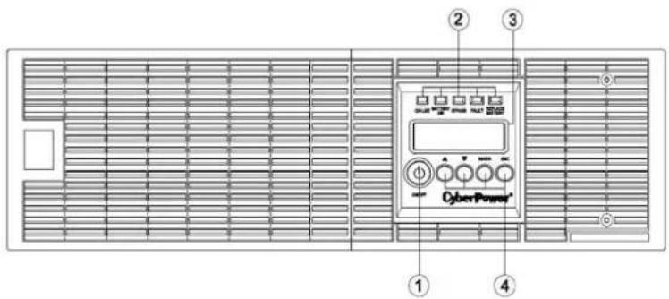
text_image
① ② ③ ④ CyberPowertext_image
⑤ ⑥ ⑦ ⑧ ⑩ ⑨ ⑪ ⑫ ⑬ ⑭ ⑫ ⑬ ⑭ ⑮ ⑯ ⑰ ⑱ ⑲ ⑳ ⑪ ⑫ ⑬ ⑭ ⑮ ⑯ ⑰ ⑱ ⑲ ⑳ ⑪ ⑫ ⑬ ⑭ ⑮ ⑯ ⑰ ⑱ ⑲ ⑳ ⑪ ⑫ ⑬ ⑭ ⑮ ⑯ ⑰ ⑱ ⑲ ⑳ ㉑ ㉒ ㉓ ㉔ ㉕ ㉖ ㉗ ㉘ ㉙ ㉚ ㉛ ㉜ ㉝ ㉞ ㉟ ㉳ ㉟1234567890000000000000000000000000000000000000000000000000000000000000000000000000000000000000000000000000000OL6000ERT3U

text_image
⑤ ⑥ ⑦ ⑧ ⑩ ⑨ ⑪ 10 ⑪ 12 13 14 INPUT GRAVES AIR LUND NONCIRITICAL LOAD 200A~ 100A~ OUTPUT MAIN RESET CONTROL PORT OUTPUT RESET CONTROL PORT OUTPUT RESET CONTROL PORT OUTPUT RESET CONTROL PORT OUTPUT RESET CONTROL PORT OUTPUT RESET CONTROL PORT OUTPUT RESET CONTROL PORT OUTPUT RESET CONTROL PORT OUTPUT RESET CONTROL PORT OUTPUT RESET CONTROL PORT OUTPUT RESET CONTROL PORT OUTPUT RESET CONTROL PORT OUTPUT RESET CONTROL PORT OUTPUT RESET CONTROL PORT OUTPUT RESET CONTROL PORT OUTPUT RESET CONTROL PORT OUTPUT RESET CONTROL PORT OUTPUT RESET CONTROL PortOL8000ERT3U / OL10000ERT3U
13. Relay Output Connector
Convert UPS signals into real potential-free Dry Contacts for industrial control.
14. SNMP/HTTP Network slot
Slot to install the optional SNMP card for remote network control and monitoring.
15. Extended Runtime Battery Module Connector
Connection for additional CyberPower XL Battery modules.
16. EPO (Emergency Power Off) Connector
Enables an emergency UPS Power-Off from a remote location.
17. Backfeed Protection Connector
Prevents power feedback from the inverter to utility power in case of power failure and a fault in the bypass circuit.
BASIC OPERATION
BATTERY MODULE FRONT/REAR PANEL DESCRIPTION
- On-board Replaceable Fuse Cover Replaceable fuse is accessible from the rear panel. It must be done by qualified personnel.
- AC Circuit Breaker Provides overload and fault protection.
- AC Output Outlet Use this outlet to connect to the AC Input Inlet of a downstream Battery module.
- AC Input Inlet (Charge Only) AC power connectivity to wall receptacle.
- Input Connector Use this input connector to daisy chain the next Battery module. Remove the connector cover for access.
- Output Cable Use this output cable to connect the Battery module to the Power module or to the next Battery module.

natural_image
Floor plan layout with grid lines and room labels (no readable text or symbols)
text_image
FUSB PSP+ VGA AC INPUT Charge Drop AC OUTPUT BATTERY OUTPUT Battery Battery INPUT Charge Drop ① ② ③ ④ ⑤ ⑥BPE240V30ART3U / BPE240V50ART3U
CONNECTION #1 : POWER MODULE WITH ONE BATTERY MODULE
Step 1: Loosen the two screws to remove the battery cable retention bracket of the power module.
Step 2: Use the output cable of the Battery module to connect the Battery module to the Power module.
Step 3: Rotate the battery cable retention bracket and tighten the two screws to fix battery cable.
Step 4: Use a power cord to plug AC input inlet of the battery module into a wall receptacle.

natural_image
Pure mechanical diagram showing a bracket and coil assembly without any text, numbers, or symbols
natural_image
Mechanical assembly diagram showing a shaft and housing with directional arrows indicating motion (no text or symbols)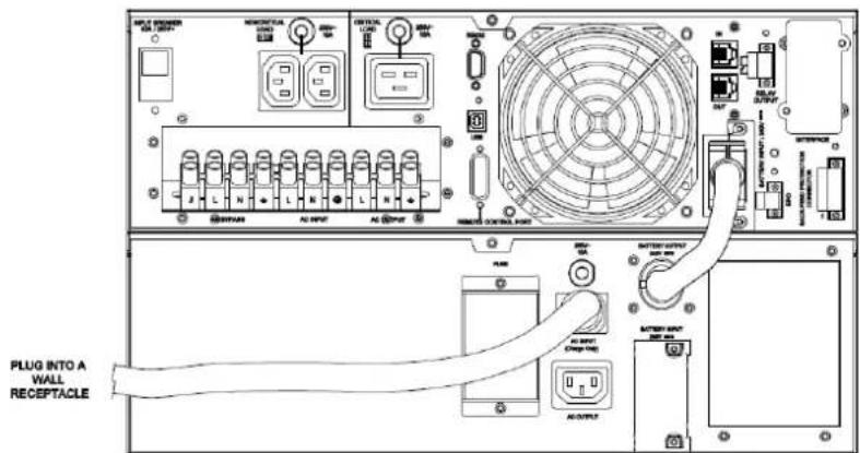
text_image
PLUG INTO A WALL RECEPTACLEBASIC OPERATION
CONNECTION #2 : POWER MODULE WITH MULTIPLE BATTERY MODULES
Step 1: Connect the 1^st Battery module to the Power module using the instructions above.
Step 2: Loosen the two screws to remove the battery cable retention bracket of the 1^st battery module.
Step 3: Use the output cable of the 2^nd Battery module to connectthe2 nd Battery module to the 1^st Battery module.
Step 4: Rotate the battery cable retention bracket and tighten the two screws to fix battery cable.
Step 5: Use a power cord to plug AC input inlet of the 2^nd battery module into AC output outlet of the 1 ^st Battery module.
text_image
Technical diagram showing mechanical assembly with labeled components and directional arrows indicating motion or force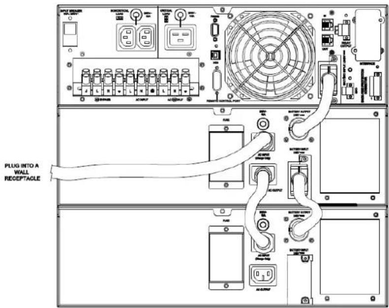
text_image
INPUT SWITCH WAL-2017 RESET/UL LED INTRAL LED POWER CONTROL PORT RMS BATTERY INPUT 100Vrms PLUG INTO A WALL RECEPTACLE RMS BATTERY INPUT 100Vrms RMS BATTERY INPUT 100Vrms RMS BATTERY INPUT 100Vrms RMS BATTERY INPUT 100Vrms RMS BATTERY INPUT 100Vrms RMS BATTERY INPUT 100Vrms RMS BATTERY INPUT 100Vrms RMS BATTERY INPUT 100Vrms RMS BATTERY INPUT 50MHz RMS BATTERY INPUT 50MHz RMS BATTERY INPUT 50MHz RMS BATTERY INPUT 50MHz RMS BATTERY INPUT 50MHz RMS BATTERY INPUT 50MHz RMS BATTERY INPUT 50MHz RMS BATTERY INPUT 50MHz RMS BATTERY INPUT 50MHz RMS BATTERY INPUT 50MHz
text_image
ON-LINE BATTERY ON BYPASS FAULT REPLACE BATTERY ON/OFF ENTER ESC CyberPower®LED INDICATORS - UPS STATUS
| LED Indicators | Color UPS Status Description |
| ON/OFF | Blue UPS power is on. |
| ON-LINE | Green UPS is operating in Line Mode. |
| BATTERY ON | Yellow UPS is operating in Battery Mode. |
| BYPASS | Yellow UPS is operating in Bypass Mode, Manual Bypass or ECO (Economy) Mode. |
| FAULT | Red UPS has an internal fault. See “Trouble Shooting” for additional information. |
| REPLACE BATTERY | Red Battery will soon need to be replaced due to insufficient runtime. |
LCD SCREEN - UPS STATUS
| LCD Screen UPS Status Description | |
| Line Mode | UPS is operating in Line Mode. |
| Battery Mode | UPS is operating in Battery Mode. |
| Bypass Mode | UPS is operating in Bypass Mode. |
| Manual Bypass | UPS is operating in Manual Bypass. |
| ECO Mode | UPS is operating in ECO (Economy) Mode. |
BUTTON OPERATION
| Button Operation Description | |
| ON/OFF | Press this button to turn on or turn off UPS. |
| ▲ | Press this button to scroll up in the LCD menu. |
| ▼ | Press this button to scroll down in the LCD menu. |
| ENTER | Press this button to select an option. |
| ESC | Press this button to cancel or return to previous LCD menu. |
MULTI-FUNCTION LCD MAIN MENU
Press "Enter" button to activate "MAIN MENU".
| MAIN MENU submenu Function Description | |
| Information | Displays the UPS information. |
| Configure | Displays the UPS settings that can be configured by the user. |
| Event Log | Displays the 3 most recent events, by event count, time (day/hour/minute), and event description. |
LCD INFORMATION READOUT
There are 19 types of UPS information available for display.
- Press the "ENTER" button to activate the "MAIN MENU".
- Press the “▲” and “▼” buttons to scroll to the “Information” option.
- Press the "ENTER" button to select the "Information" submenu.
- Press the “▲” and “▼” buttons to scroll through the “Information” submenu in the following table.
- Press the "ESC" button to return to UPS Status.
| Information Submenu | Description |
| O/P Volt = XXX.XV | Displays the Output Voltage |
| O/P Freq = XX.XHz | Displays the Output Frequency |
| I/P Volt = XXX.XV | Displays the Input Voltage |
| I/P Freq = XX.XHz | Displays the Input Frequency |
| O/P Load = XXX% | Displays the Output Load Percentage of Maximum load |
| O/P Amp = X.XA | Displays the Output Current |
| O/P Watt =XXXXW | Displays the Output Wattage |
| O/P VA =XXXXVA | Displays the Output VA |
| BAT Volt = XXX.XV | Displays the Battery Voltage |
| BAT Cap = XXX% | Displays the Estimated Percentage of Battery Capacity |
| BAT Runtime=XXXM | Displays the Estimated Battery Runtime in Minutes |
| EBM Number= X | Displays the External Battery Module Number |
| TEMP =XX°C / XXX°F | Displays the Approximate inside Temperature in both °C (Celsius) and °F (Fahrenheit) for the UPS |
| SBM =XXXXX | Displays the Stage of Smart Battery Management |
| Rating = XXK VA | Displays the UPS Rating |
| MCU Ver =XXXXX | Displays the MCU Firmware Version |
| Model Name | Displays the UPS Model Name |
| Date & Time----/---/--- | Displays the present Date & Time |
| Next BAT ChangeXXX /XXXXX | Displays the next Battery Change Date & Time |
LCD EVENT LOG
3 Event Logs of UPS can be recorded.
- Press the "ENTER" button to activate the "MAIN MENU".
- Press the “▲” and “▼” buttons to scroll to the “Event Log” option.
- Press the "ENTER" button to select the "Event Log" submenu.
- Press the “▲” and “▼” buttons to scroll through the “Event Log” submenu in the following table.
- Press the "ESC" button to return to UPS Status.
Event Log Submenu Description
| (X) | XXDXXHXXM (without PowerPanel® Business or RMCARD302) |
| -- / -- --:-- (with PowerPanel® Business or RMCARD302) | |
| Event Content |
MULTI-LANGUAGE INTERFACE
Users can configure 1 of the 3 available languages for display.
([English], [Español-Spanish], [Français-French])
- Press the "ENTER" button to activate the "MAIN MENU".
- Press the “▲” and “▼” buttons to scroll to the “Configure” option.
- Press the "ENTER" button to select the "Configure" submenu.
- Press the “▲” and “▼” buttons to scroll through the “Language” options.
- Press the "ENTER" button to select the "Language" submenu.
- Press the “▲” and “▼” buttons to scroll to the language that you want to select.
You may be prompted to save the selection, if so press the "ENTER" button to save the setting. - Press the "ESC" button to cancel or return to previous LCD menu.
LCD SETTINGS CONFIGURATION
There are 20 UPS settings that can be configured by the user.
- Press the "ENTER" button to activate the "MAIN MENU".
- Press the “▲” and “▼” buttons to scroll to the “Configure” option.
- Press the "ENTER" button to select the "Configure" submenu.
- Press the “▲” and “▼” buttons to scroll to the “Configure” submenu in the following table.
- Press the "ENTER" button to select the setting you want to configure.
The first configuration parameter will be displayed on the second column of LCD screen. - Press the “▲” and “▼” buttons to scroll through the different parameters.
- Press the "ENTER" button to select the parameter you want to change.
- Press the "ESC" button to cancel or return to the previous LCD menu.
You may be prompted to save the selection, if so press the "ENTER" button to save the setting. Some options are saved and started automatically. (See the following table for additional details.)
| Configure Submenu Available Settings Default Setting | ||
| Output Voltage | = [200V] [208V] [220V] [230V] [240V] 230V* | |
| Sync Freq Window | Range= [+/- 1%] [+/- 2%] [+/- 3%] [+/- 4%] [+/- 5%] [+/- 6%] [+/- 7%] [+/- 8%] [+/- 9%] [+/-10%] | +/- 5% |
| Bypass V Window | Range= [+10%/-10%] [+10%/-15%] [+10%/-20%] [+15%/-10%] [+15%/-15%] [+15%/-20%] | +10%/-15% |
| Bypass Condition | [Check Freq/Volt] [Check Volt Only] [No Bypass] | Check Freq/Volt |
| ECO Mode** | [Disable] [Enable] Disable | |
| [V Range= +/-15%] [V Range= +/-10%] (for [Enable]) V Range= +/-10% | ||
| Manual Bypass | [Disable] [Enable] Disable | |
| Battery Test | [Activate?] None | |
| Audible Alarms | [Disable] [Enable] Enable | |
| EBM Number | = [0] [1] [2] [3] [4] [5] [6] [7] [8] [9] [10] 0 | |
| Wiring Fault | [Disable] [Enable] Enable | |
| NCL Control | [Outlet On] [Outlet Off] Outlet On | |
| Language | [English] [Deutsch-German] [Français-French] | English |
| Generator Mode*** | [Disable] [Enable] Disable | |
| Communication | [Disable] [Enable] Enable | |
| Dry Relay Set | [I/P Power Fail] [Battery Low] [Summary Alarm] [UPS On Bypass] [UPS Fail] | I/P Power Fail |
| Converter Mode**** | [Converter Off] [O/P Freq = 50Hz] [O/P Freq = 60Hz] Converter OFF | |
| Screen Saver | [Disable] [1 Minutes] [5 Minutes] 5 minutes | |
| Clear Event Log | [Activate?] None | |
| Button OFF LOCK | [Disable] [Enable] Disable | |
| Charger Function | [SBM] [Constant] SBM | |
*) Output voltage default setting depends on different nation or order requested.
**) This function can't be set when Manual Bypass, Generator Mode or Converter Mode is enabled.
***) UPS has no bypass when Generator Mode is enabled.
^**** UPS has no bypass when Converter Mode is enabled. This function can only be set before the UPS is on.
SILENCING AUDIBLE ALARMS
- Press any of four function buttons on the LCD module; Note: the alarm can not be turned off for a "Battery Low" condition. This condition will still result in an audible alarm.
- Configure "Audible Alarms" as "Disable" on the LCD module and it will stop warning of any malfunction audibly.
MANUAL BATTERY TEST
Configure "Battery Test" as "Active" on the LCD module; and it will perform the "Manual Battery Test"
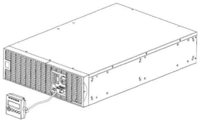
REMOTE CONTROL
Step 1: Remove the Multifunction LCD Module
Unscrew the right panel of the Power module. Separate the right panel from the UPS. Gently lift the LCD module out. Reinstall the right panel.
Step 2: Connect the DB26 Cable
Connect the DB26 cable from LCD module to the "Remote Control Port" on the front panel or rear panel as shown in the following figure.
natural_image
Line drawing of an electronic device with ventilation grilles and a connected power supply unit (no text or symbols)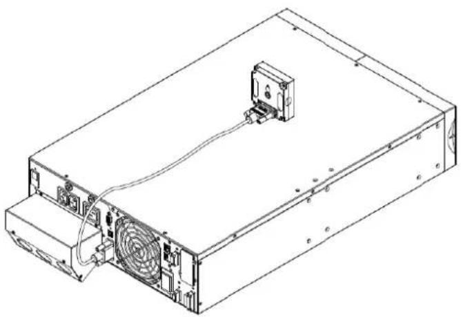
natural_image
Line drawing of an electronic device chassis with cooling fan and drive unit (no text or symbols)WALL-MOUNTING INSTRUCTIONS
Step 1: Remove the Multifunction I CD Module
Unscrew the right panel of the Power module. Separate the right panel from the UPS. Gently lift the LCD module out. Reinstall the right panel.
Step 2: Rotate the DB26 Connector of LCD Module
Step 3: Connect the DB26 Cable
Connect the DB26 cable from LCD module to the "Remote Control Port" on the front panel or rear panel as shown in the following figure.
Step 4: Mount LCD Module on the Wall
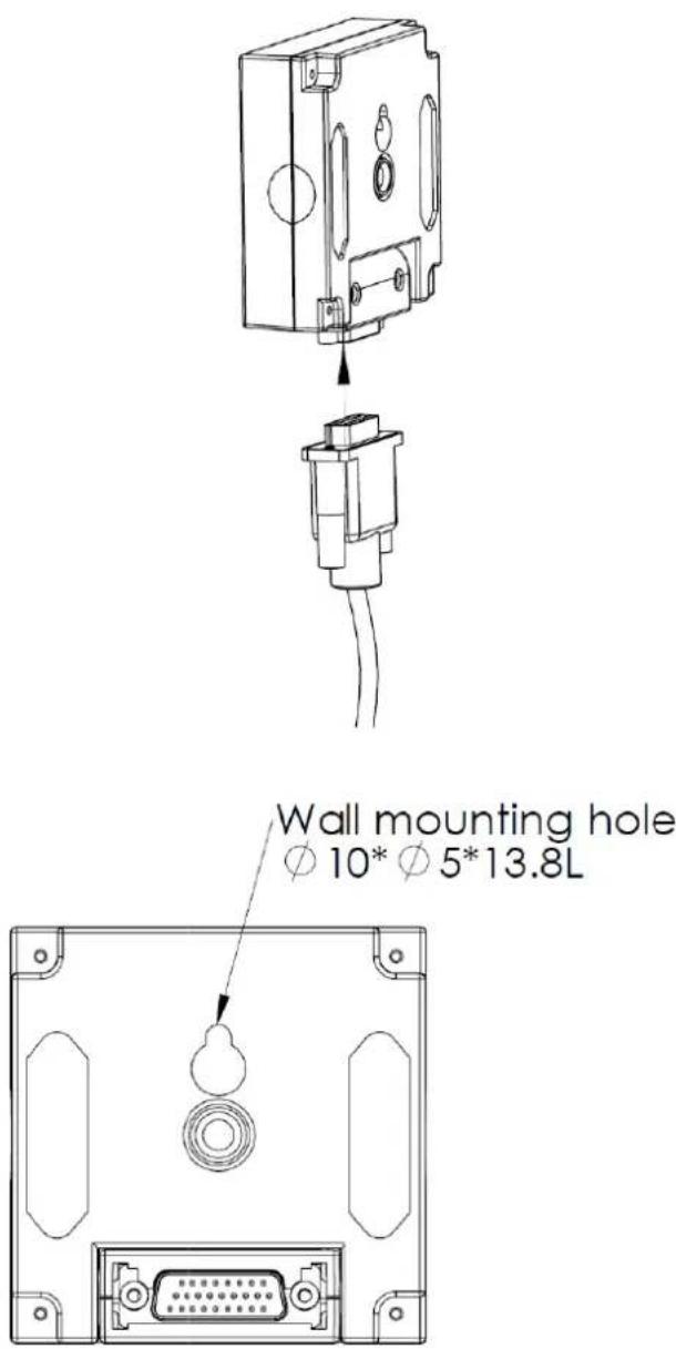
text_image
Wall mounting hole Ø 10* Ø 5*13.8LSAFETY PRECAUTIONS
CAUTION! It must be done by qualified personnel.
CAUTION! To avoid electric shock, turn off and unplug the unit before installing REMOTE CONTROL or WALL-MOUNTING INSTRUCTIONS.
MAINTENANCE
Storage
To store your UPS for an extended period, cover it and store with the battery fully charged. Recharge the battery every three months to ensure battery life.
Battery Replacement
Please read and follow the Safety Instructions before servicing the battery. Battery replacement should be performed by trained personnel who are familiar with the procedures and safety precautions. Make a note of the replacement Battery module number.
Safety Precautions
CAUTION! Only use replacement batteries which are certified by CyberPower Systems. Use of incorrect battery type is an electrical hazard that could lead to explosion, fire, electric shock, or short circuit.
CAUTION! Batteries contain an electrical charge that can cause severe burns. Before servicing batteries, please remove any conductive materials such as jewelry, chains, wrist watches, and rings.
CAUTION! Do not open or mutilate the batteries. Electrolyte fluid is harmful to the skin/eyes and may be toxic.
CAUTION! To avoid electric shock, turn off and unplug the UPS from the wall receptacle before servicing the battery.
CAUTION! Only use tools with insulated handles. Do not lay tools or metal parts on top of the UPS or battery terminals.
Replacement Batteries
Please refer to the front side of the Battery module for the model number of the correct replacement batteries. For battery procurement, log onto www.CPSww.com, or contact your local dealer.
Battery Disposal
Batteries are considered hazardous waste and must be disposed of properly. Contact your local government for more information about proper disposal and recycling of batteries. Do not dispose of batteries in fire.
Battery Installation

natural_image
Technical diagram of a structural assembly with internal components and mounting holes (no text or labels)Step 1: Remove the front panels
natural_image
Technical line drawing of a structural assembly with beams and supports (no text or symbols)Step 2: Remove the retaining screws from the cable protection cover and then remove the cover itself
natural_image
Technical line drawing of a mechanical assembly with two rectangular components and mounting holes (no text or symbols)Step 3: Pull the battery trays out slowly and then put the new battery trays back into the compartment

natural_image
Technical line drawing of a mechanical assembly with cross-sectional views (no text or symbols)Step 4: Insert the battery connectors and tighten the screws of battery retaining cover

natural_image
Technical line drawing of an industrial cooling unit with heat exchangers and cooling fins (no text or labels)Step 5: Install the front panels
TECHNICAL SPECIFICATIONS
| Model | OL6000ERT3UD | OL8000ERT3UD | OL10000ERT3UD | |
| Configuration | ||||
| Capacity (VA) 6000VA | 8000VA 10000VA | |||
| Capacity (Watts) 5400W | 7200W 9000W | |||
| Form Factor Rackmount / Tower | ||||
| Energy-saving Technology Yes, ECO Mode Efficiency >95% | ||||
| Input | ||||
| Input Voltage Range | 120~139Vac for 0~25% Load140~159Vac for 0~50% Load160~179Vac for 0~75% Load180~280Vac for 0~100% Load | |||
| Input Frequency Range | 40~70Hz | |||
| Input Power Factor | 0.99 | |||
| Cold Start | Yes | |||
| Output | ||||
| Output Waveform | Sine wave | |||
| Output Voltage* | 200, 208, 220, 230, 240Vac (Configurable) ±2% | |||
| Output Frequency 50/60Hz (Auto-Sensing or Configurable) ±0.25Hz | ||||
| Transfer Time (Typically) | 0ms | |||
| Rated Power Factor | 0.9 | |||
| Harmonic Distortion | THD < 3% at Linear Load, < 5% at Non-linear Load | |||
| Crest Factor | 3:1 | |||
| ECO Mode Voltage Regulation | ±10%, ±15% (Configurable) | |||
| UPS Outlets | (2) IEC C13, (1) IEC C19, (1) Terminal block | |||
| Protection | ||||
| Surge Protection | IEC 61000-4-5 Level 3 | |||
| Phone / Network Protection | RJ11/RJ45 (One In/One Out) | |||
| Overload Protection | Line Mode: 105~125% Load for 1 min, 126~150% Load for 10 secBattery Mode: 105~130% Load for 10 sec, 131~150% Load for 2 sec | |||
| Short Circuit Protection | UPS Output Cut off Immediately or Input Fuse / Circuit Breaker Protection | |||
| Battery | ||||
| Specifications | (20) 12V/7.2AH | (20) 12V/9.0AH | ||
| Recharge Time (Typically) | 4 hours | 5 hours | ||
| Sealed, Maintenance Free | Yes | |||
| Hot-Swappable | Yes | |||
| Status Indicators | ||||
| LCD Screen | Multi-Function LCD Readout that Supports:Multi-Language Interface, (19) Types of Read Out,(20) Types of Function Setting, (3) Event Logs | |||
| LED Indicators | Power On (Blue), Line Mode (Green), Battery Mode (Yellow),Bypass Mode (Yellow), Fault (Red), Replace Battery (Red) | |||
| Audible Alarms | Battery Mode, Battery Low, Overload, UPS Fault, Replace Battery | |||
| Environment | ||||
| Operating Temperature | 32°F to 104°F (0°C to 40°C) | |||
| Operating Relative Humidity | 0 to 90% Non-Condensing | |||
| Management | ||||
| On-Device Features | Self Test, Auto-Charge, Auto-Restart, Auto-Overload Recovery | |||
| Connectivity Ports | (1) Serial Port (RS232), (1) USB Port, (1) Remote Control Port, (1) Relay Out | |||
| SNMP/HTTP Capable | (1) Expansion Port (With optional SNMP card or RMCARD 302) | |||
| Software | ||||
| Power Management Software | PowerPanel®Business Edition | |||
| Physical | ||||
| Dimensions--Power Module | L x W x H = 26 x 17 x 5.2in. (66 x 43.3 x 13.2cm) | |||
| Dimensions--Battery Module | L x W x H = 26 x 17 x 5.2in. (66 x 43.3 x 13.2cm) | |||
| Net Weight--Power Module | 53lbs(24Kg) | |||
| Net Weight--Battery Module | 167.2lbs(76Kg) | 171.6lbs(78Kg) | ||
| Safety | ||||
| Conformance Approvals | CE, C-tick | |||
| Problem | Possible Cause | Solution | ||
| Warning | ||||
| O/P Overload | Your equipment requires more power than the UPS can provide. If the UPS is in Line Mode then it will transfer to Bypass Mode; if the UPS is in Battery Mode it will shutdown. | Shut off non-essential equipment. If this solves the overload problem, the UPS will transfer to normal operation. | ||
| Load Over XXX% | Your equipment requires more power than the setting in the Power Management Software (PowerPanel® Business) will allow. | Shut off the non-essential equipment or increase the level in the Power Management Software. | ||
| Battery Mode UPS is operating on battery power. | Save your data and perform a controlled-shutdown. | |||
| Battery Low | UPS is operating on battery power and will be shutting down soon due to extremely low battery voltage. | UPS will restart automatically when acceptable utility power returns. | ||
| BAT Disconnected Missing battery power. Check battery connector and battery breaker. | ||||
| Battery Failure UPS has failed in Battery Test. | 1. Check battery connector and battery breaker.2. Contact technical support to replace the battery. | |||
| Replace Battery | Battery will soon need to be replaced due to insufficient runtime. | Contact technical support to replace the battery. | ||
| EPO OFF Missing the EPO connection. Check the EPO connection. | ||||
| Wiring Fault | Line and neutral wires are reversed. Exchange line and neutral wires. | |||
| Missing ground wire. Connect ground wire. | ||||
| No ground wire. Disable Wiring Fault alarm on LCD panel. | ||||
| Line Abnormal | Wrong utility power backed up during UPS auto-restart. | Check whether voltage or frequency of utility power is out of range. | ||
| Output Short Output short circuit. | Your attached equipment may have problems, please remove them and check again. | |||
| Over Temperature | High ambient temperature. | Check the fan for operation and if the ventilation hole has been covered. | ||
| Coldstart Lock | UPS is locked to prevent consuming battery power during shipping. | Plug into utility power for first-time operation. | ||
| Autorestart Lock | "Automatic Restore" is disabled in Power Management Software (PowerPanel® Business) | Press "ON/OFF" button to turn on UPS | ||
| Bypass Forbidden | Manual Bypass Forbidden when the LCD screen shows "Generator On" or "Converter On". | Slide the Interlock Bracket to the right. (For the PDU or HW PDU only) | ||
| Fault | ||||
| Over Charge | Battery is overcharged. | 1. Remove battery connector and check charger voltage.2. Contact CyberPower for repair. | ||
| Charger Failure | Charger has failed. | |||
| High O/P V | Output voltage is too high. | 1. Shut down UPS and turn off input breaker.2. Contact CyberPower for repair. | ||
| Low O/P V | Output voltage is too low. | |||
| Bus Fault | Internal DC bus voltage is too high or too low. | |||
CyberPower Systems Inc.
www.cpsww.com
Entire contents copyright ^® 2011 CyberPower Systems Inc., All rights reserved. Reproduction in whole or in part without permission is prohibited. PowerPanel ^® Business Edition and PowerPanel ^® Personal Edition are trademarks of CyberPower Systems Inc.