
PR1000RT2UCN - UPS CyberPower - Free user manual and instructions
Find the device manual for free PR1000RT2UCN CyberPower in PDF.

| Product Type | Uninterruptible Power Supply (UPS) - Line Interactive |
| Model | CyberPower PR1000RT2UCN |
| Power Capacity | 1000 VA / 1000 W |
| Input Voltage | 100/110/120/125V (nominal) |
| On Battery Output Voltage | 100/110/120/125V ± 5% |
| On Battery Output Waveform | Pure Sine Wave |
| Automatic Voltage Regulation (AVR) | Yes, boost/buck |
| Surge Protection | 2430 Joules |
| Battery Type | Sealed Maintenance-Free Lead Acid |
| Replacement Battery Pack | CyberPower RB1270X4H |
| Typical Recharge Time | 3 hours to 90% from total discharge |
| Outlets | Battery-backed and surge-protected outlets (quantity not specified, but multiple) |
| Form Factor | 2U Rackmount / Tower convertible |
| Dimensions (W x H x D) | 17.1 x 3.4 x 16.2 inches (433 x 86.5 x 412 mm) |
| Weight | 50.1 lbs (22.7 kg) |
| Input Plug | NEMA 5-20P |
| Communication Ports | USB, Serial, SNMP/HTTP slot, Cloud Monitoring Ethernet, Dry Contact, EPO/ROO |
| Included Software | PowerPanel Business (local) and PowerPanel Cloud (remote) |
| GreenPower UPS Technology | Yes, Energy Star compliant, RoHS |
| Operating Temperature | 32°F - 104°F (0°C - 40°C) |
| Safety Approvals | UL1778, CSA C22.2 No 107.3, FCC Class B |
| Battery Replacement | Toolless access, user-replaceable |
Frequently Asked Questions - PR1000RT2UCN CyberPower
User questions about PR1000RT2UCN CyberPower
0 question about this device. Answer the ones you know or ask your own.
Ask a new question about this device
Download the instructions for your UPS in PDF format for free! Find your manual PR1000RT2UCN - CyberPower and take your electronic device back in hand. On this page are published all the documents necessary for the use of your device. PR1000RT2UCN by CyberPower.
USER MANUAL PR1000RT2UCN CyberPower
PRODUCT REGISTRATION
Thank you for purchasing a CyberPower product. Please take a few minutes to register your product at www.cyberpowersystems.com/registration. Registration certifies your product's warranty, confirms your ownership in the event of a product loss or theft and entitles you to free technical support. Register your product now to receive the benefits of CyberPower ownership.
INTRODUCTIONS
The CyberPower Smart App Sinewave Uninterruptible Power Supply PR750RT2UC/ PR1000RT2UC/ PR1500RT2UC/ PR2000RT2UC/ PR2200RT2UC/ PR3000RT2UC/ PR750RTXL2UC/ PR1000RTXL2UC/ PR1500RTXL2UC/ PR2000RTXL2UC/ PR2200RTXL2UC/ PR3000RTXL2UC features 2430 Joules of surge protection, provides battery backup during power outages and is Active PFC compatible for safeguarding mission-critical servers, telecom equipment, VoIP and internetworking hardware that require seamless sine wave power. Its full Automatic Voltage Regulation (AVR) boost/buck technology delivers a consistent and clean AC power, protecting connected equipment and preventing costly business interruptions. This UPS is GreenPower UPS™ Bypass circuitry patented to save on energy costs by reducing energy consumption and heat buildup.
The UPS unit incorporates microprocessor-based full digital control and includes PowerPanel® Business software providing the user unsurpassed flexibility and control. An optional SNMP/HTTP Remote Management adapter (RMCARD) supports remote management and control of the machine through a standard web browser.
AUTOMATIC VOLTAGE REGULATOR (AVR)
The incoming utility power may be damaging to important data and hardware, but with Automatic Voltage Regulation, the computer will not experience damaging voltage levels. The AVR automatically increases low or decreases high voltage to a safe and consistent output voltage.
CyberPower GreenPower UPS Technology
CyberPower's patented GreenPower UPS with Bypass Technology are ENERGY STAR® complainant ensuring lower power consumption and energy costs compared to conventional UPS models. Even when utility power is normal, conventional UPS models constantly pass power through a transformer. By contrast, under normal conditions the advanced circuitry of a GreenPower UPS bypasses the transformer. As a result, the power efficiency is significantly increased while decreasing waste heat, using less energy, and reducing energy costs.
When an abnormal power condition occurs, the GreenPower UPS automatically runs power through its transformer to regulate voltage and provide "safe" power. Since utility power is normal over 88% of the time, the GreenPower UPS operates primarily in its efficient bypass mode.

The GreenPower UPS is also manufactured in accordance with the Restriction on Hazardous Substances (RoHS) directive making it one of the most environmentally-friendly on the market today.
IMPORTANT SAFETY INSTRUCTIONS (SAVE THESE INSTRUCTIONS)
This manual contains important instructions that should be followed during installation and maintenance of the UPS and batteries. Please read and follow all instructions thoroughly before and during the installation and operation of the product.
CAUTION! The UPS must be connected to a grounded AC power outlet with fuse or circuit breaker protection. DO NOT plug the UPS into an outlet that is not grounded. If you need to de-energize this equipment, turn off and unplug the UPS.
CAUTION! The battery can energize hazardous live parts inside even when the AC input power is disconnected.
CAUTION! To prevent the risk of fire or electric shock, install in a temperature and humidity controlled indoor area, free of conductive contaminants. Please see specifications for acceptable temperature and humidity range.
CAUTION! For pluggable equipment, the socket-outlet shall be installed near the equipment and shall be easily accessible.
CAUTION! To reduce the risk of electric shock, do not remove the cover, except to service the battery. There are no serviceable parts inside, except for the battery.
CAUTION! To avoid electrical shock, turn off the unit and unplug it from the AC power source before servicing the battery or installing a computer component.
CAUTION! When installing the equipment, ensure that the sum of the leakage current of the UPS and the connected equipment does not exceed 3.5mA.
CAUTION! Do not unplug the unit from AC Power during operation, as this will invalidate the protective ground insulation.
CAUTION! To reduce the risk of fire, connect only to a circuit provided with 20 amperes maximum branch circuit overcurrent protection in accordance with the National Electric Code, ANSI/NFPA 70. (PR750RT2UC/ PR1000RT2UC/ PR1500RT2UC/ PR2000RT2UC/ PR750RTXL2UC/ PR1000RTXL2UC/ PR1500RTXL2UC/ PR2000RTXL2UC)
CAUTION! To reduce the risk of fire, connect only to a circuit provided with 30 amperes maximum branch circuit overcurrent protection in accordance with the National Electric Code, ANSI/NFPA 70. (PR2200RT2UC/PR3000RT2UC/PR2200RTXL2UC/PR3000RTXL2UC)
CAUTION! DO NOT USE FOR MEDICAL OR LIFE SUPPORT EQUIPMENT! DO NOT use in any circumstance that would affect operation or safety of any life support equipment, with any medical applications, or patient care.
CAUTION! DO NOT USE WITH OR NEAR AQUARIUMS! To reduce the risk of fire, do not use with or near aquariums. Condensation from the aquarium can come in contact with metal electrical contacts and cause the machine to short out.
CAUTION! DO NOT INSTALL THE UPS WHERE IT WOULD BE EXPOSED TO DIRECT SUNLIGHT OR NEAR A STRONG HEAT SOURCE!
CAUTION! DO NOT BLOCK OFF VENTILATION OPENINGS AROUND THE HOUSING!
CAUTION! DO NOT USE THE UPS ON ANY TRANSPORTATION! To reduce the risk of fire or electric shock, do not use the unit on any transportation such as airplanes or ships. The effect of shock or vibration caused during transit and the damp environment can cause the unit to short out.
CAUTION! Dispose of or recycle the UPS after the end of its life in accordance with local regulations.
UNPACKING
When you receive the unit, the package should contain the following items:
- UPS Unit
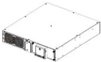
natural_image
Isometric line drawing of a rectangular electronic device with ventilation slots and a central door (no text or symbols)- Faceplate
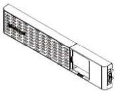
natural_image
Isometric line drawing of a rectangular electronic device with internal grid structure (no text or symbols)- Rail Kit CP2RAIL02

natural_image
Technical line drawings of mechanical components or brackets (no text or symbols)
(14) M5 Pan Head Screw (8) Plastic Washers
Note: It is available for PR3000RT2UC/ PR1500RTXL2UC/ PR2000RTXL2UC/ PR2200RTXL2UC/ PR3000RTXL2UC.
- Management Cable

(1) USB Cable

-
User's Manual

-
Mechanical Accessory

BASIC CONFIGURATION
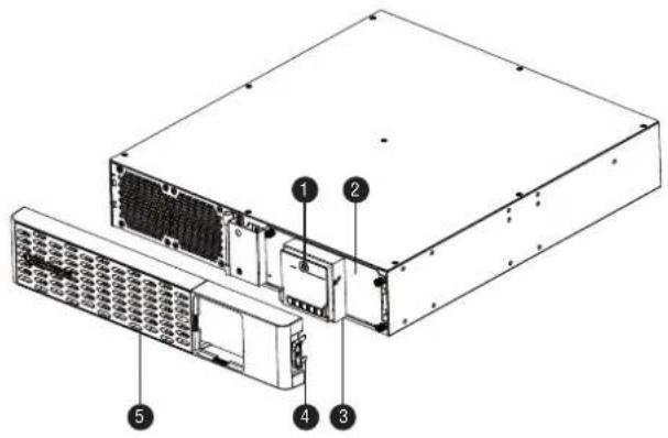
Front Panel
- Power Switch
- Toolless Battery Access Door
- LCD Module
- Front Panel Access Tabs
- Faceplate
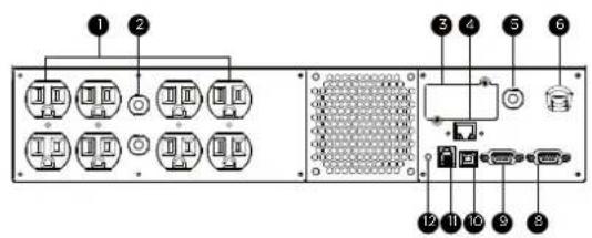
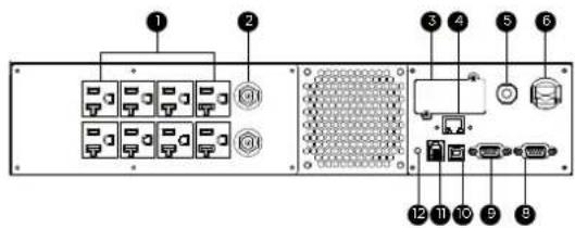
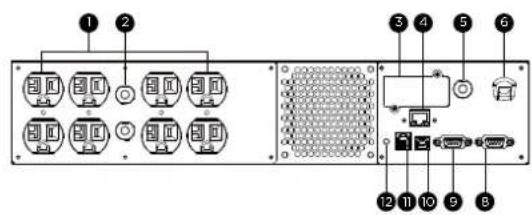
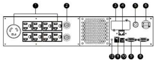
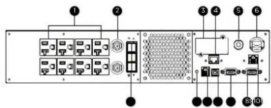
Rear Panel
- Battery Backed and Surge Protected Outlet
- Output Circuit Breaker
- SNMP/HTTP Network Slot
- Cloud Monitoring (Ethernet Port)
- Input Circuit Breaker
- AC Inlet
-
BM Port
-
Dry Contact
- Serial Port
- USB Port
- EPO/ROO Port
-
TVSS Screw
-
Extended Battery Module Connector Socket
BM Port
Connection port for built-in battery management module on extended battery module.
PR750RT2UC / PR1000RT2UC / PR1500RT2UC
PR2200RT2UC
PR750RTXL2UC / PR1000RTXL2UC

PR2000RT2UC
PR3000RT2UC
PR1500RTXL2UC

BASIC CONFIGURATION (continued)
PR2000RTXL2UC
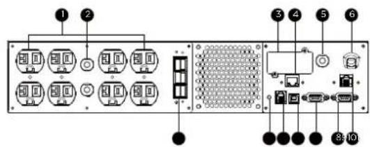
PR3000RTXL2UC

PR2200RTXL2UC
INSTALLATION
The product is designed for tower installation and rack installation for 2-post rack and 4-post rack. Read and follow the procedures thoroughly before and during your installation of the product.
The installation videos are available online. Scan the QR code below for detailed information.
Preparation
CAUTION! It is strongly recommended to have an additional person assist this installation process if the product is heavy.
CAUTION! It is strongly recommended that the 2-post rack be bolted to the floor prior to the installation of the product.
- Remove all equipment connected to the product.
- Make sure the product is disconnected from AC power source.
- Remove internal batteries to reduce weight of the unit before the installation. Refer to BATTERY REPLACEMENT section for instructions.
Rack Installation for 2-post Rack
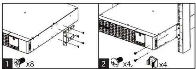

- Attach the brackets with provided M5 flat head screws.
- Affix the product to the rack with suitable M5/M6 screws and cage nuts. (M5 trust head screws are provided with the product in the mechanical accessory box.)
INSTALLATION (continued)
Rack Installation for 4-post Rack
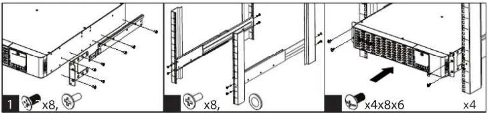

- Use the provided M5 flat head screws to attach the brackets and provided M5 pan head screws for hanging brackets.
- Screw the hanging rails to the rack with provided M5 pan head screws and plastic washers.
- Lift the product upon the hanging rails and slide the unit into the rack. Affix the product to the rack with provided M5 truss head screws. If handles are needed, affix them to the brackets with M4 flat head screws.
Note: The Rail Kit is included for selected models. See UNPACKING section. For other models, it is also available for purchase. Part number CP2RAIL02.
Tower In st al lation


- Attach the brackets to the baseplate with the provided M4 flat head screws.
- Remove the faceplate and rotate the LCD module, then re-install the faceplate.
- Screw the rubber feet with provided M4 round head screws and then put the UPS onto the assembled tower stand. You can also put the dust covers in the screw holes on the top side of the UPS to prevent dust from falling into the unit.
BASIC OPERATION
Normal Use
- Properly install the UPS.
- Connect equipment to the outlets on the rear panel of UPS.
- Plug the UPS into a 2 pole, 3 wire grounded receptacle/ wall outlet.
- Press the power switch on LCD module once. The display screen will light up and show "UPS On/Off" on the first line. Use the Up/Down button to select "On" or "Delay On" and then press the Enter button to turn on the UPS. The display screen will show CyberPower in the first line and the UPS model in the second line. Then the Online or On Battery Indicator on the LCD module lights up, indicating the UPS is operating from utility or battery.
- To turn off the UPS, press the power switch on LCD module once. The display screen will light up and show "UPS On/Off" on the first line. Use the Up/Down button to select "Off" or "Delay Off" and then press the Enter button to turn off the UPS. The display screen will show "Goodbye" and all the indicators will be off.
IMPORTANT! For first time usage, plug your UPS into an AC outlet to disable cold start protection. Otherwise, your UPS will not turn on.
IMPORTANT! Do not use an adapter, line conditioner, or other surge protection devices between the wall outlet and the UPS. Use of such a device may impede proper operation of the UPS.
BASIC OPERATION (continued)
Be aware of the following statements:
A. Your UPS may be used immediately upon receipt. However, charging the battery for at least 12 hours is recommended to ensure the battery reaches its maximum charge. Charge loss may occur during shipping and storage. To recharge the battery, simply leave the unit plugged into an AC outlet. The unit will charge in either the on or off state.
B. To maintain optimal battery charge, leave the UPS plugged into an AC outlet at all times.
C. DO NOT plug a laser printer, copier, space heater, vacuum, paper shredder, pumps or other large electrical device to the UPS. The power demands of these devices will possibly overload and damage your UPS.
D. Always plug the UPS into a 2 pole, 3 wire grounded receptacle/ wall outlet. Make sure the wall branch outlet is protected by a fuse or circuit breaker and does not service equipment with large electrical demands, e.g. air conditioner, refrigerator, copier, etc. Avoid using extension cords.
E. To prevent the risk of electric shock, follow the steps to ground the UPS:
(a) Connect a ground wire to the TVSS screw on the rear panel of UPS.
(b) Connect another side of the ground wire to the ground.
F. If your UPS freezes, you can do a hard reboot as below steps.
(a) Press and hold the power switch on the LCD module for around 15\~20 seconds; the UPS will be forcibly shut down. All indicators, display screen, and output will be off immediately.
(b) After an abnormal shutdown, the UPS restarts itself when it is powered by utility. If the UPS does not restart automatically, slightly press the power switch on LCD module once to wake up the UPS to perform the auto-restart function.
When there is no utility, you need to follow below procedures to turn on the UPS. Slightly press the power switch on LCD module once. The display screen will light up and show "UPS On/Off" on the first line. Use the Up/Down button to select "On" or "Delay On" and then press the Enter button to turn on the UPS. The display screen will show CyberPower in the first line and the UPS model in the second line. Then the On Battery Indicator on the LCD module lights up, indicating the UPS is operating from battery.
Note: When the UPS is off, pressing and holding the power switch for around 15-20 seconds cannot turn on the UPS even though the display screen will light up for a few seconds. Follow above steps to correctly turn on the product.
CLEANING AND MAINTENANCE
CAUTION! To reduce the risk of electric shock, do not remove the cover except to service the battery. There are no user serviceable parts inside except for the battery. For battery replacement, please refer to BATTERY REPLACEMENT section.
CAUTION! Turn off the unit and unplug it from the AC power source before cleaning.
CAUTION! Never immerse the unit in water or other liquids. Only use a soft, slightly damp cloth to wipe the surface of the unit. Do not use a spray directly to clean or disinfect the unit.
To store the product for an extended period, cover it and store with the battery fully charged. While in storage, recharge the battery every 3 months to ensure battery life.
To prevent risk of fire or electric shock, install or place the unit in a temperature and humidity controlled indoor area, free of conductive contaminants.
| Operation | Temperature 32°F - 104°F / 0°C - 40°C | |
| Relative Humidity 0% - 95% Non-condensing | ||
| Elevation 0 - 9,843 feet / 0 - 3,000 meters | ||
| Storage | Temperature 5°F - 113°F / -15°C - 45°C | |
| Relative Humidity 0% - 95% Non-condensing | ||
| Elevation | 0 - 49,213 feet / 0 - 15,000 meters | |
NETWORK OPERATION
Local Monitoring
Connect either the USB cable or Serial cable to the corresponding port on the UPS and on the computer with PowerPanel Business software installed. PowerPanel Business software is available on our website. Please go to www.cyberpowersystems.com/products/software/power-panel-business for the free download.
Note: USB and Serial port cannot be used simultaneously. Serial port will be disabled if the USB port is used.
Remote Monitoring
This product is equipped with a SNMP/HTTP network slot. If you would like to control the UPS from a remote location, especially under a private network, a CyberPower Remote Management Card (RMCARD) is required. For more information, visit www.cyberpowersystems.com.
Cloud Monitoring
This product features an Ethernet port for Cloud Connection, which makes it easy to monitor CyberPower UPS systems from anywhere. Follow below steps to get your UPS on Cloud.
- Hardware installation: Connect the Cloud Monitoring (Ethernet Port) on the UPS rear panel to a wall jack or network switch using a suitable Ethernet cable.
 | LED Indicators Conditions | |
| Link | Off The UPS is not connected to the Network. | |
| On (Yellow) The UPS is connected to the Network. | ||
| Tx/Rx | Off The Cloud Monitoring (Ethernet Port) is not powered. | |
| On (Green) The Cloud Monitoring (Ethernet Port) is powered. | ||
| Flashing - Receiving/transmitting data packet | ||
- Application installation: Install PowerPanel Cloud App on your smartphone and then launch the application. PowerPanel Cloud application is available for download on the Apple App Store or Google Play.


- Sign up and login.
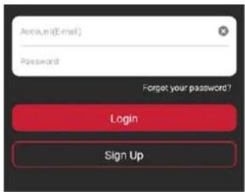
NETWORK OPERATION (continued)
- Add a device in the PowerPanel Cloud App.
(a) Click "+" in the upper right corner of the homepage.
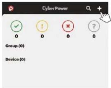
(b) Locate the "Add Device by QR Code" to add your Cloud UPS.
(c) Scan the QR Code on the top side of the UPS. If the QR Code scan was successful, click "Add" and name the device you are monitoring.
(d) After the setup is completed, you will see your device on the homepage.
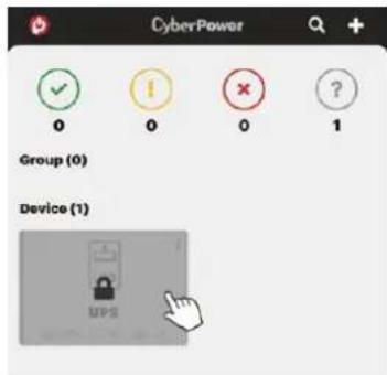
(e) Wait till the UPS is successfully configured.

- Start monitoring your UPS!
In addition to the Mobile App, you can access the PowerPanel Cloud account via a web browser: https://powerpanel.cyberpower.com. For more information, please refer to the PowerPanel Cloud User's Manual.
LCD OPERATION GUIDE
Display Interface
- Power Switch/Power On Indicator
- Online Indicator
- Fault/Warning Indicator
- On Battery Indicator
- Battery Fault Indicator
- Display Screen
- Menu Button
- Esc Button
- Up Button
- Down Button
- Enter Button

Basic Operation
Press Up/Down Button to scroll through the UPS status. Press Esc button to go back to top.
| Menu | Item | ||
| Status | Operation ModeInput Voltage InformationOutput Voltage Information | Estimated RuntimeBattery InformationLoad Information | NCL StatusUPS TemperatureDate and Time |
LCD Setting Guide
Press Menu Button to enter Setup Menu and use Up/Down Button to scroll through menus. Press Enter Button to go into the selected menu and use the Up/Down Button and Enter Button to select the setting item and to complete the setting. Esc Button is pressed to exit the submenu and go back to previous page.
| Menu | Item | |||
| Basic Setup | · Utility Quality | · Sensitivity | · Extended Battery Module Quantity* *Select models | |
| Ambient Setup | · Eco ModeLED Brightness | · LCD HibernationCycling Display | · Audible Alarm | |
| Outlet Control | · UPS Configuration | · NCL Configuration | ||
| Test | · Self Test | · Alarm Test | ||
| Logs | · Event 1-10 | |||
| About | · UPS Model NameUPS Serial NumberLast Battery Change DateNext Battery Change Date | · UPS Firmware VersionIP AddressMAC IDService Port Number | · BM StatusUPS Battery Information | |
| Advanced Setup | · Output VoltageMinimum Output VoltageMaximum Output VoltageLow Battery ThresholdBattery Change Date | · Schedule TestDate and TimePower Meter RestIP AccessIP Address | · Subnet MaskGatewayFirmware Update**Back to Default**Only displayed in standby mode | |
Menu / Basic Setup
In order to better supply power to the connected equipment, it is recommended to check settings in this menu before you start using your UPS.
| Item | Default | Option | Description |
| Utility Quality Normal | GoodNormalPoor | Select the voltage quality of the input utility power.If Good is selected, the UPS will be more sensitive to power quality and go to battery mode more often to supply the cleanest power to connected devices.If Poor is selected, the UPS will tolerate more power fluctuations and go to battery mode less often. | |
| (Customized) | “Customized” shows up when Maximum/Minimum Output Voltage has been adjusted in Advanced Setup Menu or through software. | ||
| Sensitivity | Medium | HighMediumLow | Select the sensitivity level to power events for connected equipment.If the connected equipment is highly sensitive to power events, select High; the UPS will go to battery mode more often to provide the cleanest power.If the connected equipment can tolerate more power events, select Low; the UPS will go to battery mode less often. |
| Extended Battery Module Quantity* | 0 | 0-10Auto-sensing | If Auto-sensing is selected, the UPS will change the numbers automatically. |
Menu / Ambient Setup
The settings in this menu affect the UPS display, alarm, and noise. Customize your UPS to meet your needs.
| Item | Default | Option | Description |
| Eco Mode Active | ActiveInactive | When Active is selected, the UPS will change related setup functions in this menu automatically to work under low energy consumption. | |
| Active (Customized)Inactive(Customized) | You can also set the functions in this menu independently and then go back to Eco Mode to have a check. If Active is displayed, the UPS works under low energy consumption. | ||
| LED Brightness Dim | BrightNormalDimOnly Power On | The LED brightness can be set in accordance with the ambient lights or different usage scenario.If Only Power On is selected, all LED indicators will be off except Power On Indicator. | |
| LCD Hibernation After 1 minute | NeverAfter 1 minuteAfter 5 minutesAfter 10 minutes | After this amount of time with no activity, the display screen will shut off to save energy. | |
| Cycling Display Never | NeverAfter 10 secondsAfter 20 secondsAfter 30 seconds | After this amount of time with no activity, UPS will start cycling the status information on display screen. | |
| Audible Alarm Quiet | Normal contains fault and warning alarms and all reminding alarms of battery operation including switching to battery power, working under battery mode, reaching Low Battery Threshold, soon running out of battery, and Low Battery Shutdown.If Quiet is selected, the UPS will emit fault and warning alarms and reminding alarm indicating the UPS reaches Low Battery Threshold.If Mute On Battery is selected, only fault and warning alarm will sound.All alarms are disabled if Off is selected. | ||
Menu / Outlet Control
Use this menu to configure UPS outlet performance. Outlets are divided into Critical (CL) and Non-Critical (NCL) outlets. Connect the mission critical devices into Critical outlets and nonessential equipment into NCL outlets. If equipment needs to be shut down or reboot in a specific order, plug the equipment into separate outlet groups.
Enter the submenu "Config UPS" to configure the total output of the UPS, including CL and NCL outlets. Enter "Config NCL" if you want to have additional settings for NCL outlets, for example, cut off the power provision to the nonessential equipment during a blackout to reserve runtime for mission critical devices.
| Item | Default | Option | Description | |
| Delay Turn On | 4 seconds | ·0-600 seconds | The amount of time that the outlets will wait before actual startup. | |
| Delay Turn Off | 4 seconds | ·0-600 seconds | The amount of time that the outlets will wait before actual shutdown. | |
| Reboot Duration | 12 seconds | ·4-300 seconds | The amount of time that the outlets will remain off before the UPS restarts itself. | |
| Minimum Restored Capacity | 0% · 0-100% | It is the criteria for UPS to perform auto-restart as utility is restored. If battery capacity is higher than this setting, the auto-restart will be performed; otherwise, the UPS will keep charging the battery until battery capacity reaches that level. | ||
| Uptime on Battery Disable | ·Enable: 5-1800 seconds·Disable | Set the maximum runtime on battery mode. The UPS will shut down after the amount of time spent in battery mode has reached this setting. Make sure the estimated runtime is larger than this setting; otherwise, the UPS will still stop supplying power when it is running out of battery. | ||
| Reserved Runtime Disable | ·Enable: 0-1800 seconds·Disable | When the UPS is in battery mode, it will cut off output power when the remaining runtime reaches the level. | ||
| NCL Switch*+Can only be configured in the Submenu, NCL Configuration. | On | ·On·Delay On·Off·Delay Off·Reboot·Delay Reboot | This is the main switch for NCL outlet groups. | |
| Off on Overload*+Can only be configured in the Submenu, NCL Configuration. | Disable | ·Enable·Disable | NCL outlets will be turned off when the UPS is overloaded in battery mode if the item is enabled. NCL outlets will turn on automatically as utility is restored. | |
Menu / Test
This menu provides basic tests for users to check the current performance of the UPS.
| Item | Default | Option | Description |
| Self Test No | YesNo | Select Yes to order the UPS to quickly test the backup function by entering to battery mode, checking if it works. The test takes around 10 seconds. | |
| Alarm Test Short Test | Short TestContinuous Test | This item tests the alarm's audible warning and LED indicators' functionalities. Short test lasts 5 seconds. In continuous testing, press any button to stop the test. |
Menu / Logs
All kinds of events are recorded and the UPS will show the last 10 events in this menu. Events are categorized into four sorts and shown in a capital letter in a single event log on the display screen: (F) Fault, (W) Warning, (S) Shutdown, and no letter for a normal transfer event.
Menu / Advanced Setup
This menu contains more adjustable and detailed items for UPS advanced usage. Read the item descriptions below thoroughly before you change the settings.
| Item | Default | Option | Description | |
| Output Voltage | 120V* *Select models and regions | · 100V · 110V · 120V · 127V | Select the AC output voltage on battery mode. | |
| Minimum Output Voltage | 100V: 89V | · 100V: 86-92V | Set the value lower if the utility voltage is usually low to avoid unnecessary battery usage. | |
| 110V: 97V | · 110V: 97-106V | |||
| 120V: 102V | · 120V: 97-106V | Make sure the connected equipment can work under the voltage condition. | ||
| 127V: 111V | · 127V: 108-114V | |||
| Maximum Output Voltage | 100V: 111V | · 100V: 108-114V | Set the value higher if the utility voltage is usually high to avoid unnecessary battery usage. | |
| 110V: 128V | · 110V: 127-136V | |||
| 120V: 131V | · 120V: 127-136V | Make sure the connected equipment can work under the voltage condition. | ||
| 127V: 143V | · 127V: 140-146V | |||
| Low Battery Threshold | 300 seconds · 0-1800 seconds | The UPS will emit an audible alarm indicating that the remaining runtime is reaching its threshold. | ||
| 35% · 20-65% | The UPS will emit an audible alarm indicating that the remaining battery capacity is reaching its threshold. | |||
| Item | Default | Option | Description | |
| Battery Change Date | ----/---- | Month/Year | Optional setup information for users to record the installation date of battery pack. Reset the data when replacing new battery pack. | |
| Schedule Test - On Startup | No | YesNo | If Yes is selected, the UPS will perform a Self Test every time on startup. | |
| Schedule Test - Frequency | Never | NeverEvery 1 weekEvery 2 weeksEvery 3 weeksEvery 4 weeks | Select the amount of time that the UPS will perform Self Test periodically after startup. | |
| Date and Time ----/--/-- ---:--- | Year/Month/Day Hour:Minute | Set the Date and Time for use in data/event logs. | ||
| Power Meter Reset No | YesNo | Select Yes to reset the value of Load Energy in Status Menu. | ||
| IP Access DHCP | DHCPManual IP Setup | Select the way to access the IP/Subnet Mask/Gateway. This shows “No Web Device” when no RMCARD is installed. | ||
| IP Address Auto-sensing | Auto-sensingManual Key-in | Change the IP Access setting to manual IP Setup and then this item can be adjusted manually. This shows “No Web Device” when no RMCARD is installed. | ||
| Subnet Mask Auto-sensing | Auto-sensingManual Key-in | Change the IP Access setting to manual IP Setup and then this item can be adjusted manually. This shows “No Web Device” when no RMCARD is installed. | ||
| Gateway | Auto-sensingAuto-sensingManual Key-in | Change the IP Access setting to manual IP Setup and then this item can be adjusted manually. This shows “No Web Device” when no RMCARD is installed. | ||
| Firmware Update*Only displayed in Standby Mode | No | YesNo | Select Yes to update the firmware of UPS in Standby Mode. | |
| Back to Default No | YesNo | Select Yes to restore the UPS factory default settings. | ||
Fault Warning Display and Alarm
The following table shows the fault and warning indications of the UPS. The warning message cycles when the UPS is still turned on. Refer to the error code below and take necessary measures.
After the UPS shuts down or is turned off manually, the error message could disappear but the event records can be found in the Log Menu. To safely check the logs, press the power switch once and then press the Esc button to enter another operation mode - Standby Mode. Press Menu button and go to Log Menu to do a check.
Note: When the UPS is in Standby Mode, it does not have output. All indicators will not illuminate and only the display screen lights up when the UPS is operated. To leave the Standby Mode, refer to BASIC OPERATION section to turn on the UPS. Or you can disconnect the UPS from the AC power source, wait for a minute, and then UPS will completely become off.
| Display ScreenLine 1 | Display ScreenLine 2 | LED Indicator Alarm | |
| UPS Fault! | E01-Overcharge: Contact CyberPower for repair. | ⚠️ | Beeps once every 2 seconds* |
| UPS Fault! E03-No Charge: Contact CyberPower for repair. | ⚠️ | - | |
| UPS Off! E20-Output Short: Connected equipment may have problems, remove them and check. | ⚠️ | Beeps for 3 seconds | |
| UPS Off! E21-Output Short: Connected equipment may have problems, remove them and check. | ⚠️ | Beeps for 3 seconds | |
| Warning! / UPS Off! E22-Overload: Unplug at least one connected device. | ⚠️ | Constant alarm* | |
| Warning! | E23-Over Temp.: Turn off the unit and check ventilation. | ⚠️ | Beeps once every 2 seconds* |
| Warning! | E24-Over Temp.: Turn off the unit and check ventilation. | ⚠️ | Beeps once every 2 seconds* |
| UPS Off! E25-EPO: Check the EPO connector status. - - | |||
| Warning! E27-Fan Fail (FR): Contact CyberPower for repair. | ⚠️ | - | |
| Warning! E27-Fan Fail (FL): Contact CyberPower for repair. | ⚠️ | - | |
| Warning! E29-Fan Fail (B): Contact CyberPower for repair. | ⚠️ | - | |
| Warning! Battery Disconnected: Check battery wiring and condition. | (Flashes) | Beeps once every 2 seconds for a period of 30 seconds* | |
| Warning! Battery Defect: Check battery wiring and condition. | (Flashes) | Beeps once every 2 seconds for a period of 30 seconds* | |
| Warning! Service Battery: Batteries have reached recommended maintenance period. | - | - | |
| Warning! Wiring Fault: Check utility wiring and ground. - - | |||
*Press any button to cancel the alarm.
The Emergency Power Off (EPO) port is a safety feature that can be used to immediately shut down the UPS and cut off its power supply to connected equipment. It is necessary to manually press the power switch on the LCD module to restart the UPS and reapply power to connected equipment.
The Remote On/Off (ROO) shares the same port with EPO and those two functions can be used at the same time. ROO is a remote power control function which allows users not only to power on but also power off the UPS from a remote location.
Installation
- Verify the UPS is off and unplugged.
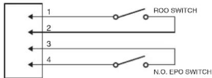
- The EPO/ROO interface is an IEC 60950 safety extra low voltage (SELV) circuit. Follow the appropriate circuit diagram below to wire the provided EPO cable to your EPO/ROO configuration. Connect isolated dry contacts and use ONLY latching switch.

4 1
OPTION 1: USER SUPPLIED NORMALLY OPEN SWITCH (RECOMMENDED)
OPTION 2: USER SUPPLIED NORMALLY CLOSED SWITCH
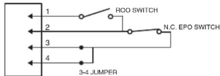
- After wiring, make sure the external EPO/ROO switch is not activated to enable UPS output.
- Plug the UPS into an AC outlet and turn the UPS on via power switch on the LCD module.
- Activate the external EPO/ROO switch to test the function. Check the status change of UPS from its LCD module.
- For EPO user: De-activate the external EPO switch and restart the UPS via power switch on the LCD model.
For ROO user: Press the external ROO switch again to restart the UPS.
Restriction on ROO
A. ROO can only turn on the UPS when utility is available.
B. ROO becomes inactive if the UPS is shut down due to Fault, Low Battery, or EPO; it is necessary to manually press the power switch on the LCD module to restart the UPS and reapply power to connected equipment.
C. ROO is active only when UPS power status is the same as ROO circuit.* If they are different, manually adjust the external ROO switch to synchronize current UPS status.
For instance, the UPS is turned off via power switch on the LCD module; however, the ROO switch stays in "on" position, which means the contact is closed. Users have to manually press the external ROO switch to "off" position, making contact open, to reactivate the ROO, verifying the power status shown on LCD module and ROO switch is on the same page. And then users can press the external ROO switch again to turn on the UPS.
*Power switch on the LCD module, software and external ROO switch can all turn on/off the UPS.
DRY CONTACT
This UPS offers users the solution for UPS status monitoring via two output relays. Refer to Network Operation in this manual, verifying the UPS is connected to a computer with PowerPanel Business software installed or is equipped with RMCARD. Follow below circuit to wire your dry contact port and choose your preferred monitoring status via those interfaces.
UPS status which can be monitored by dry contact is listed below:
| UPS Status UPS Conditions | |
| Power Failure* UPS detects utility failure. | |
| Battery Low* Battery capacity is lower than threshold. | |
| Summary Alarm | UPS exits alarms due to Inverter Fault, Output Short, Over Temperature, Overload, Battery Overcharge, Low Battery, Battery Disconnected, and Battery Defect. |
| UPS Fail | UPS has malfunctioned due to Inverter Fault, DC Power Fault, and Over Temperature. |
*Default settings of relay contacts are Power Failure and Battery Low (Normally Open).
Internal Circuit

Output Relay Rating
Voltage: 30VDC Max
Current: 3A Max (per relay)
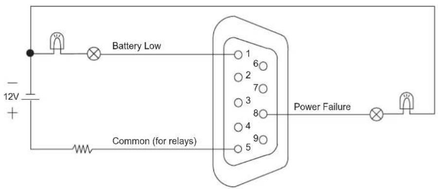
Relay Status UPS Status
Pin1 short to Pin5 Battery Low
Pin8 short to Pin5 Power Failure
Example Application
Supply 12VDC to the Common contact and connect LEDs to the DB9 port Pin1 and Pin8. When UPS detects utility failure or when UPS battery capacity is lower than threshold, the connected LEDs will illuminate.
BATTERY REPLACEMENT
Read and follow the important safety instructions before servicing the batteries. Visit CyberPower official website www.cyberpowersystems.com or contact your dealer for more information on replacement batteries.
The battery replacement video is available online. Scan the QR code below for detailed information.
CAUTION! RISK OF EXPLOSION IF BATTERY IS REPLACED BY AN INCORRECT TYPE. When replacing batteries, replace with the same number of the following battery: CyberPower RB1250X4 for PR750RT2UC, CyberPower RB1270X4H for PR1000RT2UC/ PR750RTXL2UC/ PR1000RTXL2UC, CyberPower RB1290X4J for PR1500RT2UC/ PR2000RT2UC/ PR2200RT2UC/ PR3000RT2UC/ PR1500RTXL2UC/ PR2000RTXL2UC/ PR2200RTXL2UC/ PR3000RTXL2UC.
CAUTION! Risk of Energy Hazard, 12V, maximum 6 Ampere-hour battery. (PR750RT2UC)
CAUTION! Risk of Energy Hazard, 12V, maximum 9 Ampere-hour battery. (PR1000RT2UC/ PR1500RT2UC/ PR2000RT2UC/ PR2200RT2UC/ PR3000RT2UC/ PR750RTXL2UC/ PR1000RTXL2UC/ PR1500RTXL2UC/ PR2000RTXL2UC/ PR2200RTXL2UC/ PR3000RTXL2UC)
CAUTION! The used batteries are considered hazardous waste and must be disposed through recycling. Most retailers that sell lead-acid batteries collect used batteries for recycling, as required by local regulations. Do not dispose of batteries in a fire. The batteries may explode.
CAUTION! Do not open or mutilate batteries. Released material is harmful to the skin and eyes. It may be toxic.
CAUTION! Do not replace batteries while the UPS is in battery mode.
CAUTION! When the battery pack is disconnected, the loads connected to the UPS are not protected from power failure.
CAUTION! Do not use a damaged or deformed battery pack.
Take the following precautions before replacing the battery:
- Remove watches, rings, or other metal objects.
- Use tools with insulated handles.
- Wear rubber gloves and boots.
- Do not lay tools or metal parts on top of batteries.
- Determine if battery is inadvertently grounded. If inadvertently grounded, remove source from ground. CONTACT WITH ANY PART OF A GROUNDED BATTERY CAN RESULT IN ELECTRICAL SHOCK. The likelihood of such shock can be reduced if such grounds are removed during installation and maintenance (applicable to equipment and remote battery supplies not having a grounded supply circuit).
Battery Replacement Procedure


- Remove faceplate and unscrew the thumbscrews on battery cover and then open the battery cover. Note: Thumbscrews are designed fixed on the battery cover, do not remove them from the metal cover.
- Disconnect the battery and battery management module connector.
- Insert the new battery pack. Assemble the connectors, thumbscrews and faceplate. Recharge the unit for at least 12 hours to ensure the UPS performs expected runtime.
Reminder: Battery Change Date is optional setup information for users to record the installation date of battery pack. It can be adjusted through LCD module in Advanced Setup Menu or through software.
TECHNICAL SPECIFICATIONS
| Model | PR750RT2UC | PR1000RT2UC | PR1500RT2UC | PR2000RT2UC | PR2200RT2UC | PR3000RT2UC |
| General | ||||||
| UPS Topology Line | interactive | |||||
| Energy Saving Green | Power UPS Bypass Technology | |||||
| Input | ||||||
| Nominal Input Voltage | 100/110/120/125V | 100/110/120V | ||||
| Input Frequency 50 | /60Hz +/- 3Hz (Auto-sensing) | |||||
| Plug Type | NEMA 5-15P | NEMA 5-20P | NEMA5-30P | |||
| Power Cord Length | 10ft / 3m | |||||
| Output | ||||||
| Power Capacity | 750VA/750W | 1000VA/1000W | 1500VA/1500W* | 2000VA/2000W* | 2200VA/2200W | 3000VA/3000W* |
| On Battery Output Voltage | 100/110/120/125V +/- 5% | 100/110/120V +/- 5% | ||||
| On Battery Output Frequency | 50/60Hz +/- 1% | |||||
| On Battery Output Waveform | Sine Wave | |||||
| Battery | ||||||
| Battery Type | Sealed Maintenance Free Lead Acid Battery | |||||
| Replacement Battery Pack (RBP) | RB1250X4 | RB1270X4H | RB1290X4J | |||
| RBP Quantity | 1 | |||||
| Typical Recharge Time | 3 hours to 90% from total discharge under 100% load | |||||
| Physical | ||||||
| Dimensions | 2U Rack, 17.1" x 3.4" x 16.2" / 433 x 86.5 x 412 (mm) | 2U Rack, 17.1" x 3.4" x 16.7" / 433 x 86.5 x 500 (mm) | ||||
| Weight | 43.2lbs / 19.6kg | 50.1lbs / 22.7kg | 55.8lbs / 25.3kg | 59.8lbs / 27.1kg | 59.8lbs / 27.1kg | 76.5lbs / 34.7kg |
| Conformance | ||||||
| Approvals | UL1778, CSA C22.2 No 107.3, FCC Class B, VCCI Class B, ENERGY STAR | UL1778, CSA C22.2 No 107.3, FCC Class A, VCCI Class A, ENERGY STAR | ||||
| Environmental | RoHS Compliant | |||||
*Refer below de-rating information for 100/110V systems:
PR1500RT2UC: 1200VA/1200W@100V, 1350VA/1350W@110V; PR2000RT2UC: 1600VA/1600W@100V, 1800VA/1800W@110V; PR3000RT2UC:
2400VA/2400W@100V, 2700VA/2700W@110V.
TECHNICAL SPECIFICATIONS (continued)
| Model | PR750RTXL2UC | PR1000RTXL2UC | PR1500RTXL2UC | PR2000RTXL2UC | PR2200RTXL2UC | PR3000RTXL2UC |
| General | ||||||
| UPS Topology Line | interactive | |||||
| Energy Saving Green | Power UPS Bypass Technology | |||||
| Input | ||||||
| Nominal Input Voltage | 100/110/120/125V | 100/110/120V | ||||
| Input Frequency 50 | /60Hz +/- 3Hz (Auto-sensing) | |||||
| Plug Type | NEMA 5-15P | NEMA 5-20P | NEMA 5-30P | |||
| Power Cord Length | 10ft / 3m | |||||
| Output | ||||||
| Power Capacity | 750VA/750W | 1000VA/1000W | 1500VA/1500W* | 2000VA/2000W* | 2200VA/2200W | 3000VA/3000W* |
| On Battery Output Voltage | 100/110/120/125V +/- 5% | 100/110/120V +/- 5% | ||||
| On Battery Output Frequency | 50/60Hz +/- 1% | |||||
| On Battery Output Waveform | Sine Wave | |||||
| Battery | ||||||
| Battery Type | Sealed Maintenance Free Lead Acid Battery | |||||
| Replacement Battery Pack (RBP) | RB1270X4H | RB1290X4J | ||||
| RBP Quantity | 1 | |||||
| Typical Recharge Time | 3 hours to 90% from total discharge under 100% load | |||||
| Extended Battery Module | BP48VP2U01 | BP48VP2U02 | ||||
| Physical | ||||||
| Dimensions | 2U Rack, 17.1" x 3.4" x 16.2" / 433 x 86.5 x 412 (mm) | 2U Rack, 17.1" x 3.4" x 16.7" / 433 x 86.5 x 500 (mm) | ||||
| Weight | 53.1lbs / 24.1kg | 55.3lbs / 25.1kg | 67.7lbs / 30.7kg | 74.5lbs / 33.8kg | 79.6lbs / 36.1kg | 75.4lbs / 34.2kg |
| Conformance | ||||||
| Approvals | UL1778, CSA C22.2 No 107.3, FCC Class B, VCCI Class B, ENERGY STAR | UL1778, CSA C22.2 No 107.3, FCC Class A, VCCI Class A, ENERGY STAR | ||||
| Environmental | RoHS Compliant | |||||
*Refer below de-rating information for 100/110V systems:
PR1500RTXL2UC: 1200VA/1200W@100V, 1350VA/1350W@110V; PR2000RTXL2UC: 1600VA/1600W@100V, 1800VA/1800W@110V; PR3000RTXL2UC: 2400VA/2400W@100V, 2700VA/2700W@110V.
TROUBLESHOOTING
| Problem | Possible | Cause |
| UPS does not provide power to equipment. | Circuit breaker has tripped due to an overload. | Turn the UPS off and unplug at least one piece of equipment. Wait 10 seconds, reset the circuit breaker, and then turn the UPS on. |
| Batteries are discharged. Recharge the UPS for at least 3 hour. | ||
| UPS has been damaged by a surge or spike. | Contact CyberPower for repair. | |
| Non-critical outlets have turned off automatically due to an overload in battery mode. | NCL outlets will be turned on automatically as utility is restored. To avoid recurring, check “Off on Overload” setting in Outlet Control Menu and disable the function. | |
| UPS does not perform expected runtime. | Batteries are not fully charged. Recharge the batteries by leaving the UPS plugged in. | |
| Batteries are degraded. Contact CyberPower about replacement batteries. | ||
| UPS does not recognize the correct quantity of Extended Battery Modules. | Adjust the setting of Extended Battery Module Quantity on your UPS to correct numbers via LCD module, PowerPanel Business software or RMCARD interface (if installed). | |
| UPS cannot be turned on. | UPS is not connected to an AC outlet. | The unit must be connected to a 100 - 120V or 100 - 125V outlet. (See TECHNICAL SPECIFICATIONS section) |
| Batteries are worn out. Contact CyberPower about replacement batteries. | ||
| Mechanical problem. Contact CyberPower for repair. | ||
| Part of hard reboot process has been performed. | Long press of the power switch to forcibly shut down the UPS when it freezes. When the UPS is off, long press of the power switch to light up the display screen for a few seconds. This does not turn on the UPS. Refer to BASIC OPERATION section to correctly turn on the UPS. | |
| PowerPanel Business is inactive. | The serial cable or USB cable is not connected. | Connect the cable to your UPS and computer. Use the cable that came with the unit if your own communication cable does not work. |
| The serial cable or USB cable is connected to the wrong or defected port. | Try another port on the computer. | |
| UPS is not providing battery power. | Shut down the computer and turn the UPS off. Wait 10 seconds and turn the UPS back on to reset the unit. | |
| “Service Battery” message appears on display screen. | The Battery Replacement Date has reached the recommended maintenance period. | Perform a runtime estimation via PowerPanel Business software to verify battery capacity is sufficient and acceptable. |
| If batteries have been recently replaced, reset the Battery Replacement Date using PowerPanel Business software or RMCARD interface; you can also reset the Battery Change Date in Advanced Setup Menu through LCD module. | ||
| “Fault” or “Error” message is appearing on display screen. | An internal malfunction may have occurred. | Please refer to Fault Warning Display and Alarm in the LCD OPERATION GUIDE section. If the fault persists, take note and contact CyberPower for repair. |
| UPS cannot work properly while attached to a generator. | The size of generator is not suitable for current load. | The continuous generator capacity rating must be at least twice the total load, including the UPS and all other devices attached to the generator; otherwise, the generator may not be able to hold the voltage and frequency within the input tolerance of the UPS, causing the UPS switching from utility to battery mode back and forth. Reduce the connected load or upgrade the generator. |
| The UPS is too sensitive to power events. | The quality and stability of the generator power may not be as good as your local utility. The frequent blackouts and waveform distortions could lead the UPS to consider the input power inappropriate and will switch to battery mode to provide clean power to attached load, draining the battery. Refer to LCD OPERATION GUIDE section to desensitize the UPS via LCD module, PowerPanel Business software or RMCARD interface (if installed).Note: Lowering the sensitivity setting makes the UPS tolerate more power events, but it also increases the transfer time of the UPS. Some sensitive equipment cannot accept extended transfer time. Test to check if there is a load drop when the UPS is switching to battery mode. | |
Additional troubleshooting information can be found at www.cyberpowersystems.com.
DISPOSAL

The Waste Electrical and Electronic Equipment (WEEE) Directive aims to contribute to sustainable production and consumption by contributing to the efficient use of resources and the retrieval of secondary raw materials through re-use, recycling, and other forms of recovery. The symbol on this product and/or its packaging indicates that the product must be disposed of separately from ordinary household wastes at its end of life. Contact your related WEEE management authority, local office, or your household waste disposal service about information on the recycling drop off site.
BATTERY DISPOSAL

This product contains non-spillable lead acid batteries. The used batteries are considered hazardous waste and must be disposed through recycling. Do not dispose of used batteries with your ordinary household wastes. Dispose of the batteries according to local regulations.
Note: Most retailers that sell lead-acid batteries collect used batteries for recycling, as required by local regulations.
REGULATORY COMPLIANCE
FCC Compliance Statement (PR750RT2UC/ PR1000RT2UC/ PR1500RT2UC/ PR2000RT2UC/ PR750RTXL2UC/ PR1000RTXL2UC/ PR1500RTXL2UC/ PR2000RTXL2UC)
This device complies with part 15 of the FCC rules. Operation is subject to the following two conditions: (1) this device may not cause harmful interference, and (2) this device must accept any interference received, including interference that may cause undesired operation.
Note: This equipment has been tested and found to comply with the limits for a Class B digital device, pursuant to part 15 of the FCC Rules. These limits are designed to provide reasonable protection against harmful interference in a residential installation. This equipment generates, uses, and can radiate radio frequency energy and, if not installed and used in accordance with the instructions, may cause harmful interference to radio communications. However, there is no guarantee that interference will not occur in a particular installation. If this equipment does cause harmful interference to radio or television reception, which can be determined by turning the equipment off and on, the user is encouraged to try to correct the interference by one or more of the following measures:
- Reorient or relocate the receiving antenna.
- Increase the separation between the equipment and receiver.
- Connect the equipment to an outlet on a circuit different from that to which the receiver is connected.
- Consult the dealer or an experienced radio/TV technician for help
Important: Changes or modifications not expressly approved by the party responsible for compliance could void the user's authority to operate the equipment.
Canadian Compliance Statement (PR750RT2UC/ PR1000RT2UC/ PR1500RT2UC/ PR2000RT2UC/ PR750RTXL2UC/ PR1000RTXL2UC/ PR1500RTXL2UC/ PR2000RTXL2UC)
CAN ICES-3 (B)/NMB-3(B)
VCCI Compliance Statement (PR750RT2UC/ PR1000RT2UC/ PR1500RT2UC/ PR2000RT2UC/ PR750RTXL2UC/ PR1000RTXL2UC/ PR1500RTXL2UC/ PR2000RTXL2UC)
This device complies with part 15 of the FCC rules. Operation is subject to the following two conditions: (1) this device may not cause harmful interference, and (2) this device must accept any interference received, including interference that may cause undesired operation.
Note: This equipment has been tested and found to comply with the limits for a Class A digital device, pursuant to part 15 of the FCC Rules. These limits are designed to provide reasonable protection against harmful interference when the equipment is operated in a commercial environment. This equipment generates, uses, and can radiate radio frequency energy and, if not installed and used in accordance with the instruction manual, may cause harmful interference to radio communications. Operation of this equipment in a residential area is likely to cause harmful interference in which case the user will be required to correct the interference at his own expense.
Important: Changes or modifications not expressly approved by the party responsible for compliance could void the user's authority to operate the equipment.
Canadian Compliance Statement (PR2200RT2UC/ PR3000RT2UC/ PR2200RTXL2UC/ PR3000RTXL2UC)
CAN ICES-3 (A)/NMB-3(A)
VCCI Compliance Statement (PR2200RT2UC/ PR3000RT2UC/ PR2200RTXL2UC/ PR3000RTXL2UC)
Visit our website at www.cyberpowersystems.com/support to access extensive service and in-depth support to gain the information you need about power protection. Use the website links to find answers to common questions, obtain troubleshooting tips, learn about our power management software, view warranty details, and examine product literature. Our online, self-service resources are available 24/7. CyberPower also offers assistance from our expert team of sales, technical, and product support associates.
Our Technical Support team will be happy help you with technical questions during business hours. Choose the ways described below you would like us to help you.
- Live Chat: Monday – Sunday, 24 Hours. Visit www.cyberpowersystems.com/support.
Submit a Form (recommended): Monday - Sunday, 24 Hours. Visit www.cyberpowersystems.com/support. - Email: Monday – Sunday, 24 Hours. Contact tech@cyberpower.com.
- Call Toll Free: Monday – Friday, 24 Hours. Call 1-877-297-6937 (press 1).

Technical Support is available on our website.
Visit CyberPower at www.cyberpowersystems.com to get more information.


- PRODUCT REGISTRATION
- INTRODUCTIONS
- AUTOMATIC VOLTAGE REGULATOR (AVR)
- CyberPower GreenPower UPS Technology
- IMPORTANT SAFETY INSTRUCTIONS (SAVE THESE INSTRUCTIONS)
- UNPACKING
- BASIC CONFIGURATION
- Front Panel
- Rear Panel
- BM Port
- BASIC CONFIGURATION (continued)
- INSTALLATION
- Preparation
- INSTALLATION (continued)
- Rack Installation for 4-post Rack
- Tower In st al lation
- BASIC OPERATION
- Normal Use
- BASIC OPERATION (continued)
- CLEANING AND MAINTENANCE
- NETWORK OPERATION
- Local Monitoring
- Remote Monitoring
- Cloud Monitoring
- NETWORK OPERATION (continued)
- LCD OPERATION GUIDE
- Display Interface
- LCD Setting Guide
- Menu / Basic Setup
- Menu / Ambient Setup
- Menu / Outlet Control
- Menu / Test
- Menu / Logs
- Menu / Advanced Setup
- Fault Warning Display and Alarm
- Restriction on ROO
- DRY CONTACT
- Relay Status UPS Status
- Example Application
- BATTERY REPLACEMENT
- Take the following precautions before replacing the battery:
- DISPOSAL
- BATTERY DISPOSAL
- REGULATORY COMPLIANCE
- FCC Compliance Statement (PR750RT2UC/ PR1000RT2UC/ PR1500RT2UC/ PR2000RT2UC/ PR750RTXL2UC/ PR1000RTXL2UC/ PR1500RTXL2UC/ PR2000RTXL2UC)
- Canadian Compliance Statement (PR750RT2UC/ PR1000RT2UC/ PR1500RT2UC/ PR2000RT2UC/ PR750RTXL2UC/ PR1000RTXL2UC/ PR1500RTXL2UC/ PR2000RTXL2UC)
- VCCI Compliance Statement (PR750RT2UC/ PR1000RT2UC/ PR1500RT2UC/ PR2000RT2UC/ PR750RTXL2UC/ PR1000RTXL2UC/ PR1500RTXL2UC/ PR2000RTXL2UC)
- Canadian Compliance Statement (PR2200RT2UC/ PR3000RT2UC/ PR2200RTXL2UC/ PR3000RTXL2UC)
- VCCI Compliance Statement (PR2200RT2UC/ PR3000RT2UC/ PR2200RTXL2UC/ PR3000RTXL2UC)
Brand : CyberPower
Model : PR1000RT2UCN
Category : UPS