CAB1631D - Switch StarTech.com - Free user manual and instructions
Find the device manual for free CAB1631D StarTech.com in PDF.

User questions about CAB1631D StarTech.com
0 question about this device. Answer the ones you know or ask your own.
Ask a new question about this device
Download the instructions for your Switch in PDF format for free! Find your manual CAB1631D - StarTech.com and take your electronic device back in hand. On this page are published all the documents necessary for the use of your device. CAB1631D by StarTech.com.
USER MANUAL CAB1631D StarTech.com
natural_image
Pixelated cursor arrow icon pointing right (no text or symbols)KVM Module for 1UCABCONS
CAB831D
CAB832DS
CAB1631D
Instruction Guide

natural_image
Front view of a dual-chamber network device with multiple ports (PCs) and connectors, no visible text or symbols on the modules themselves.Table of Contents
KVM Module
Introduction
Overview.... 1
Features... 2
Configurations....3
Installation
Device Connection.... 5
Initial Power-up....6
Operation
Front Panel Push Buttons.... 7
OSD (On-Screen Display) Operation.... .8
Hot-key Commands.... 13
Cascade Configuration
Connection....15
Change Configuration while Running....16
Appendices
Specifications....17
Troubleshooting....18

Please read this manual thoroughly and follow the Installation procedures to prevent any damage to the KVM Module or any connecting device.
Introduction
Overview
By combining the 1UCABCON console and KVM Module you receive the latest, most efficient way to control server rooms and multiple computers. Three models of KVM Modules are available to control from 8 to 136 servers by the 1UCABCONS console or another set of console 100ft (30m) away; it is ideal for various applications.
On-Screen Display (OSD) Menu
With a KVM Module you can name your computers, switch to a computer from a list, configure settings with easy-to-use menus and, view the name of the selected computer on-screen with a programmable time interval. The OSD menu displays the system status throughout operation.
Automatic Mouse Conversion
The KVM Module enables you to connect computers with PS/2 or serial mouse ports (using adapters supplied with the KVM Module) and control the computers from one PS/2 mouse. The KVM Module automatically identifies the mouse and switches to proper mouse protocol. This function is effective for computer ports "7" and "8".
High Video Quality
The 1UCABC CONS LCD panel supports VGA resolution up to 1024x768 without any degradation. The advanced VGA circuit design guarantees smooth and flicker-free switching from one computer to the other with cable length up to 100ft (30M)* at PC sides with a Console KVM switch.
*Tested with high-quality UL2919-rated, low-loss and shielded cables.
Features
✗ Supports both PS/2 and serial mice
Cascade configuration expands system capability
Auto-scan automatically selects computers sequentially
Supports Microsoft IntelliMouse (Pro)
✗ Hot-key functions allow easy computer access
✗ Keyboard states automatically saved and restored when switching computers
Operating system independent, transparent to all applications
Plug and play system configuration
Keyboard and mouse can be hot plugged at any time
DDC2B compatible
Supports optional multimedia module for microphones and stereo speakers
Features for OSD menu
Assign computers with unique and meaningful names
Identify and select computers by the names
✗ Programmable scan filters unused computers
Store system settings and name entries to non-volatile memory
✗ Password security locks computer from unauthorized access
Gain complete control with easy-to-use OSD interface
Features for multi-access KVM Module
Manage multiple computers from two locations
✗ Different Console may have different type of mouse i.e. generic PS/2 mouse and scroll mouse
✗ Selectable user timeout
Configurations
The KVM Module is available in both an 8 port and a 16 port model to support a variety of requirements. For applications with a large number of computers, KVM Modules can be cascaded in a master/slave configuration.
Single KVM Module Configuration
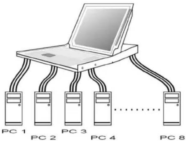
Combined with a 1UCABC CONS Console, the KVM Module can be connected to multiple computers with keyboard, mouse and monitor cables as shown in figure 1.
text_image
PC 1 PC 2 PC 3 PC 4 PC 8Figure 1: A single KVM Module configuration
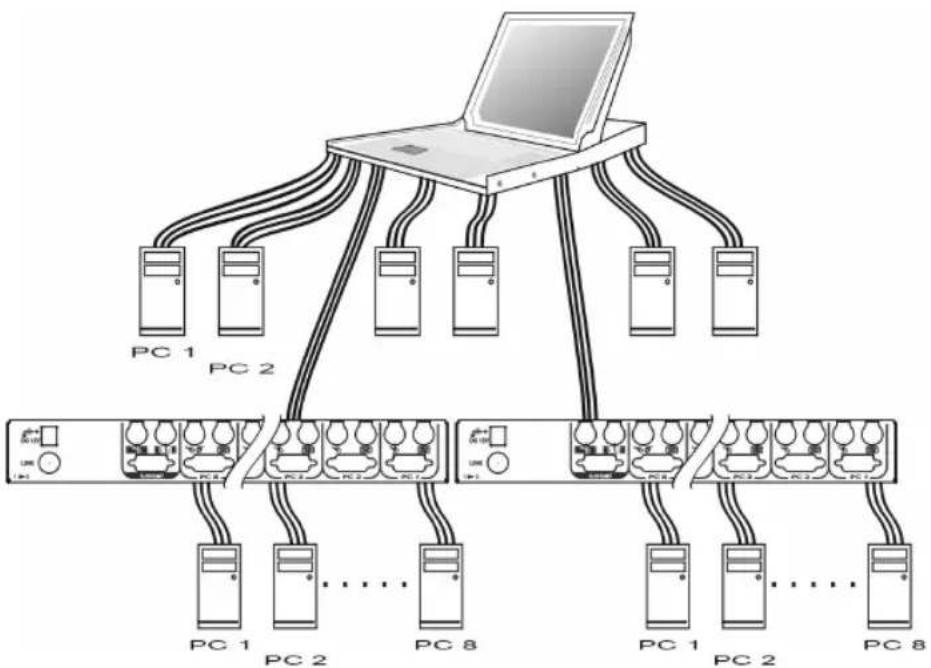
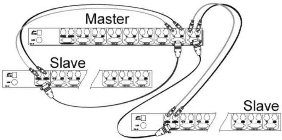
KVM Module in cascade (Master/Slave) Configuration You can connect a second level of one or more KVM Modules to "PC 1"\~"PC 8" ports of a Master unit. Cascade configuration expands system ability allowing you to select computers connected to the Master or Slaves. There is only one Master that connects to the 1UCABCONS Console directly operated by a user. Once connected, KVM Modules automatically configure themselves to either Master or Slave.
Slaves of different KVM Module models can be mixed in cascade configuration as shown in figure 2.
Note: Master must have equal or more PC ports than that of Slaves, i.e., if the master KVM module has 8 ports, the slave KVM modules can not have more than 8 ports each.
flowchart
graph TD
    A["Laptop"] --> B["PC 1"]
    A --> C["PC 2"]
    A --> D["PC 3"]
    A --> E["PC 4"]
    A --> F["PC 5"]
    A --> G["PC 6"]
    A --> H["PC 7"]
    A --> I["PC 8"]
    B --> J["Server Rack 1"]
    C --> K["Server Rack 2"]
    D --> L["Server Rack 3"]
    E --> M["Server Rack 4"]
    F --> N["Server Rack 5"]
    G --> O["Server Rack 6"]
    H --> P["Server Rack 7"]
    I --> Q["Server Rack 8"]
Figure 2: A cascaded KVM Module configuration
Throughout this manual, Master is the KVM Module that connects directly to the drawer. Slave is a KVM Module that has its CONSOLE port connected to a Master's "PC x" port. Slave only exists in cascade configuration.
Installation
Device Connection
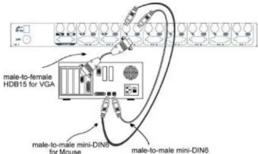
Determine the port number of each computer. For computers using PS/2 mouse, connect the computer's mouse and keyboard cables to the KVM Module's connectors marked with a mouse and keyboard respectively, as shown in figure 3. Repeat this step for PC 1 to PC 8.
text_image
male-to-female HDB15 for VGA male-to-male mini-DIN6 for Mouse male-to-male mini-DIN6Figure 3: Master computer connection
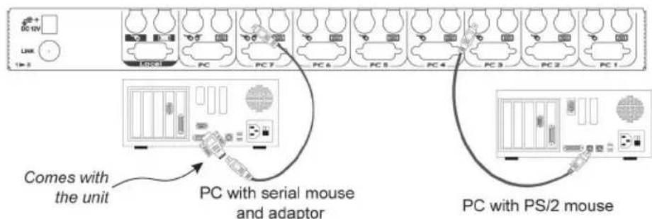
For computers using serial mice, connect the DB-9 to mini-DIN-6 adapter (included with the switch) to the computer mouse port, then use PS/2 cables to connect the mouse to the KVM Module, see figure 4. Connect the computer's monitor cable to the HD-DB-15 VGA connector. Note: This function is only available for PC 7 and PC 8 marked with two mice.
text_image
COMES WITH the unit PC with serial mouse and adaptor PC with PS/2 mouseFigure 4: Serial (AT) mouse and PS/2 mouse connection
A slave KVM Module may be mounted to the rear vertical poles inside a rack cabinet by the rear brackets with keyboard, mouse, monitor connectors facing out, as figure 5.

natural_image
Technical line drawing of a rectangular electronic component with internal wiring and mounting holes, shown with dimension lines (no text or symbols)Figure 5: Slave Console KVM switch and rear bracket attachment
The connectors (keyboard, mouse and monitor) at the Local port on the rear of the KVM module are not applicable when the module is connected to the drawer by the C-36 connector. When its C-36 connector is not connected to the drawer, the KVM module acts as a rear-mount stand-alone KVM switch.
Initial Power-Up
Make sure all computers and KVM Modules are powered down during installation. You must power up the Master KVM Module before turning on any other devices.
For single KVM Module:
1) Apply a power adapter to the Master.
2) Turn on computers.
For cascaded Console KVM switches:
1) Apply a power adapter to the Master.
2) Apply power adapters to all Slaves.
3) Turn on computers.
Note: You may hot plug additional powered-down computer or a slave KVM Module without turning any existing 1UCABCONS or computer off after initial power up.
Operation
Push Button Selection
A computer may be selected by pressing the push buttons above the keyboard in the 1UCABCONS, by issuing hot-key commands or by activating the OSD window. The indicator LEDs change to reflect the computer port selected (red). The indicator flashes red when it is in either Auto Scan or Manual Scan mode.
K/M RESET
K/M RESET solves most problems developed by keyboard, mouse, device replacement or change of configuration. Press down on both the number 1 and 2 push buttons for 2 seconds to re-configure the whole system without turning either the 1UCABCNS or any connected computer off.
AUTO SCAN
The Console KVM switch provides an easy to use feature to start Auto Scanning. You can press down both the number 7 and 8 buttons for 2 seconds to start Auto Scanning.
OSD (On-Screen-Display) Operation
flowchart
graph TD
    A["To an 8-port slave"] --> B["KVM MENU 5-6"]
    B --> C["CH Name 1 SALES-1F8 2 SALES-2F8 3 SALES-3F 4 HP-SERV 5 IBM-SRV 6 NOVEL-1 7 NOVEL-2 8 ACCOUNT F1 Edit F2 Switch F3 Security"]
    B --> D["CH Name A SHIPPING B RD-TEST1 C RD-TEST2 D E F G H"]
    B --> E["Currently selected channel address"]
    B --> F["Eye mark enabled"]
    B --> G["To a 16-port slave"]
    H["Port channel address"] --> I["Highlighted by arrow keys"]
    I --> J["Security enabled port"]
    K["Press "Enter" to the slave SALES-2F"] --> L["KVM MENU 5-6 SALES-2F"]
    L --> M["CH Name 1 US-WEST 2 US-EAST 3 US-NORTH 4 US-SOUTH 5 EUROPE 6 ASIA-N 7 ASIA-S 8 PACIFIC F1 Edit F2 Switch F3 Security"]
    L --> N["Master port name (group name)"]
    O["White as power off"] --> P["Green as power on"]
    Q["User-input port names"] --> R["F4 More Esc Quit"]
    S["Eye mark enabled"] --> T["F4 More Esc Quit"]
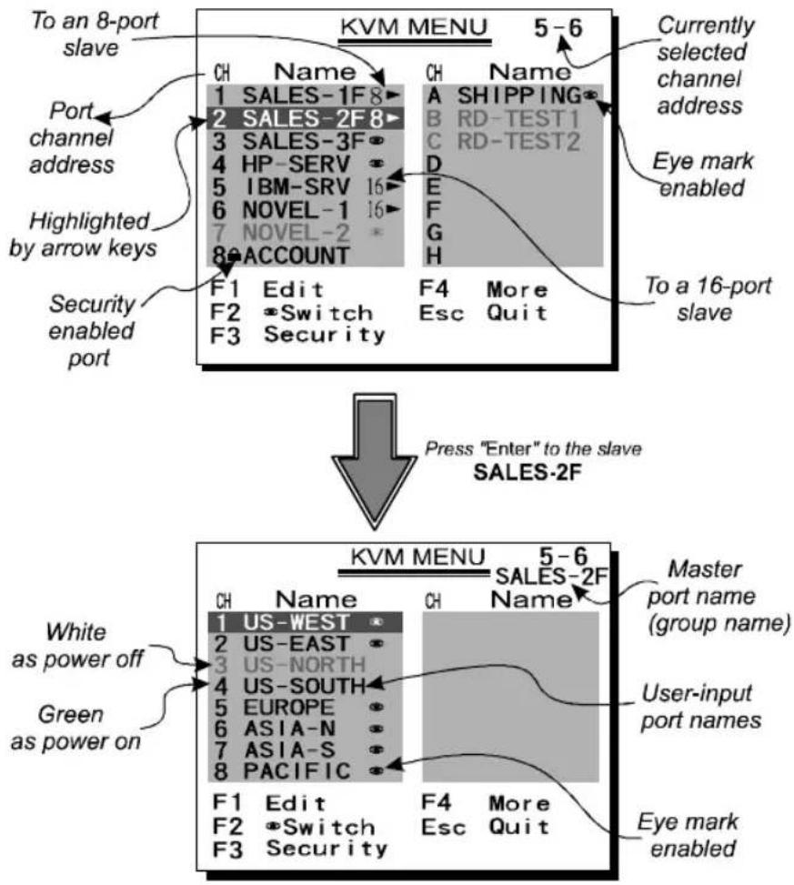
Figure 6: OSD Screen Illustration
By hitting the left
The port number of the currently selected computer is displayed in red, same as the front indicator, at the right corner of the OSD menu.
The color of a device name is green if it has power and is ready for operation, or the color is white if it has no power. OSD menu updates the color when it is activated. Use the
A triangle mark (💡) to the right of a name indicates the port is cascaded to a Slave; the number at the left of the triangle mark shows the number of ports the Slave has, i.e. 8# for an 8-port switch. The
An eye mark (☑) to the right of a name indicating the computer is selected to be monitored in Scan mode. In OSD, this mark can be switched on or off by function key
Press
Function key
Function key
Function key
If you want to access the locked device temporarily, simply highlight it and press
If you forget the password, the only way to permanently disable the security function is to remove all possible power sources from the 1UCABC CONS. You need to turn off all computers and unplug all power adapters, then restart everything.
Function key
Auto Scan
In this mode, the 1UCABCNS automatically switches from one power-on computer to the next sequentially in a fixed interval. During Auto Scan mode, the OSD displays
the name of the selected computer. When Auto Scan detects any keyboard or mouse activity, it suspends the scanning till activity stops; it then resumes with the next computer in sequence. To abort the Auto Scan mode, press the left
Manual Scan
Scan through power-on computers one by one by keyboard control. can Type (
Audio Stick
An optional multimedia module can be linked to the back of each KVM Module for selecting microphone and stereo speaker signals. There are two options for Audio Stick: ON and Off. When set to 'On', audio selection follows computer selection. When set to 'Off', audio selection stops following computer selection. It is useful if you want to listen to a particular computer's audio signal while operating other computers. The non-volatile memory stores the Audio Stick setting.
Scan Type
Ready PC + 📋: In Scan mode, scan through power-on and eye mark selected computers.
Ready PC: In Scan mode, scan through power-on computers. The non-volatile memory stores the Scan Type setting.
Scan Rate
Sets the duration of a computer displayed in Auto Scan mode. The options are 3 seconds, 8 seconds, 15 seconds and 30 seconds. The non-volatile memory stores the Scan Rate setting.
Keyboard Speed
The 1UCABCONS offers keyboard typematic setting that overrides the similar settings in BIOS and in Windows. Available speed options are Low, Middle, Fast and Faster as 10, 15, 20 and 30 characters/sec respectively. The non-volatile memory stores the Keyboard Speed setting.
Hotkey Menu
When you hit the left
CH Display
Auto Off: After you select a computer, the port number and name of the computer will appear on the screen for 3 seconds then disappear automatically. Always On: The port number and name of a selected computer and/or OSD status displayed on the screen all the time. The non-volatile memory stores the CH Display setting.
Position
The position of the selected computer name and/or OSD status displayed on screen during operation. The actual display position shifts due to different VGA resolution, the higher the resolution the higher the display position. The non-volatile memory stores the Position setting.
UL as Upper Left, UR as Upper Right, LL as Lower Left, LR as Lower Right. MI as Middle.
Hot-key commands
Hot-key command is a short keyboard sequence to select a computer, to activate computer scan, etc. The 1UCABCNS constantly interprets keystrokes for hot-keys. A hot-key sequence starts with two left
The short form hot-key menu can be turned on as an OSD function (
L-CTRL: is the
1\~8/A\~H: are the number keys '1' \~ '8' at the upper row of the keyboard and character keys 'A' \~ 'H' case insensitive. Do not use the keypad at the right of the keyboard.
To select a computer by hot-key command, you must know its port number, which is determined by the KVM Module connection. For a computer connected to a Master, its port is represented by the PC port label (1\~8 or A\~H). For a computer connected to a Slave, two characters represent its port. The first character is the port number of the Master unit (1\~8) and the second one is the port number of the Slave (1\~8 or A\~H). Please note that only Master's 'PC 1' \~'PC 8' ports can be connected to a Slave.
$$ \text { Left } \mathbf {C t r l} + \text { left } \mathbf {C t r l} + 7 $$
Selects a computer connected to port 7 of the Master.
$$ \text { Left } \mathbf {C t r l} + \text { left } \mathbf {C t r l} + 6 + \mathbf {C} $$
Selects a computer connected to port C of a Slave connected to port 6 of the Master.
To start Auto Scan, automatically scan power-on computers one by one at a fixed interval:
$$ \text { Left } \mathbf {C t r l} + \text { left } \mathbf {C t r l} + \mathbf {F 1} $$
When Auto Scan detects any keyboard or mouse activity, it suspends the scanning till activity stops; it then resumes with the next computer in sequence. The length of the Auto Scan interval (Scan Rate) is adjustable, see below. To abort the Auto Scan mode, press the left Ctrl key twice.
Note: Scan Type determines whether an eye-marked computer is to be displayed during Auto Scan.
Manual Scan enables you to manually switch back and forth between power-on computers.
$$ \text { Left } \mathbf {C t r l} + \text { left } \mathbf {C t r l} + \mathbf {F 2} $$
Press ✅ or ✅ to select the previous or the next computer in sequence. And, press any other key to abort the Manual Scan.
Note: Scan Type determines whether an eye-marked computer is to be displayed during Auto Scan.
To adjust Scan Rate which sets the duration before switching to the next computer in Auto Scan:
$$ \text { Left } \mathbf {C t r l} + \text { left } \mathbf {C t r l} + \mathbf {F 3} $$
The 1UCABCNS sends one to four beeps indicating scan interval of 3, 8, 15 and 30 seconds respectively.
To adjust keyboard typematic rate (characters/sec), this setting over-rides that of BIOS and any operating system:
$$ \text { Left } \mathbf {C t r l} + \text { left } \mathbf {C t r l} + \mathbf {F 4} $$
The 1UCABCNS generates 1 to 4 beeps corresponding to 10, 15, 20 and 30 characters/sec respectively.
Audio Stick
An optional multimedia module can be linked to the back of each 1UCABCNS for selecting microphone and stereo speaker signals. There are two options for Audio Stick: ON and Off. When set to 'On', audio selection follows computer selection. When set to 'Off', audio selection stops following computer selection. It is useful if you want to listen to a particular computer's audio signal while operating other computers.
$$ \text { Left } \mathbf {C t r l} + \text { left } \mathbf {C t r l} + F 5 $$
The 1UCABCNS generates 1 or 2 beeps corresponding to On and Off respectively.
Cascade Configuration
Connection
Before connecting a device (a computer or a Slave KVM Module) to the Master KVM Module under power, you must turn off the device. The Master must have equal or more 'PC x' ports than that of the Slave, i.e., if CAB831D or CAB832DS is the Master another 8 port KVM Module can be a slave but not the CAB1632DS.
The ports labeled "PC 1"\~"PC 8" can be connected to either a computer or a Slave's CONSOLE port, as shown in figure 7. The ports "PC A"\~"PC H" can only be connected to a computer.
flowchart
graph TD
    A["Master"] --> B["Slave"]
    B --> C["Slave"]
    C --> D["Slave"]
    style A fill:#f9f,stroke:#333
    style B fill:#ccf,stroke:#333
    style C fill:#cfc,stroke:#333
Figure 7: Slave console connection
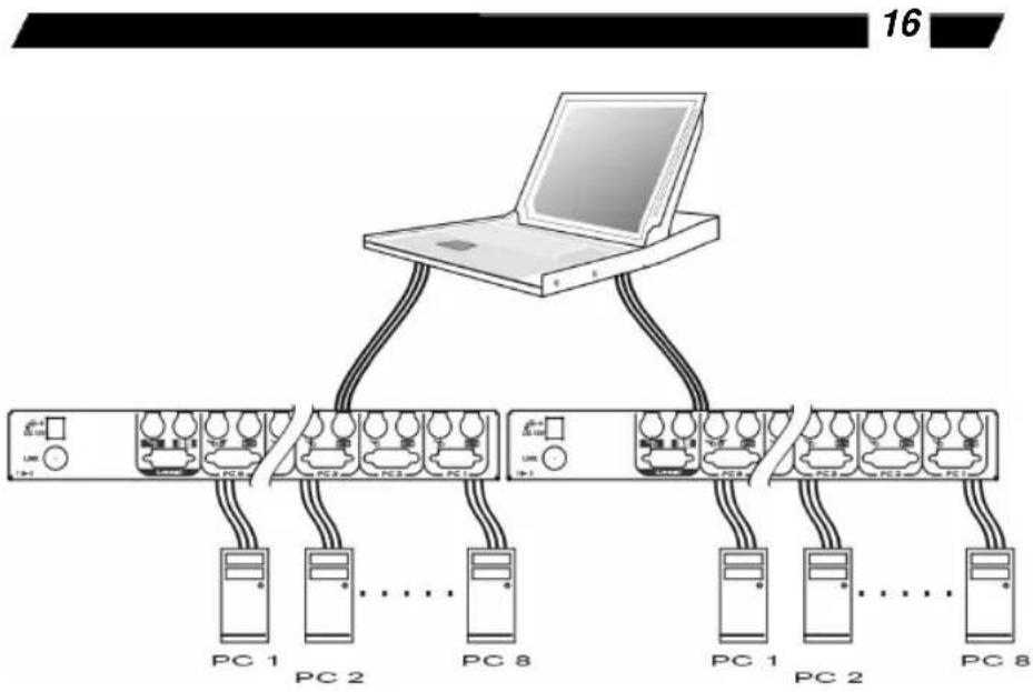
The maximum number of computers controlled by a master/slave configuration with all 8 port units is 64 -- with 8 Slaves and each Slave connects to 8 computers, see figure 8.
flowchart
graph TD
    A["Laptop"] --> B["PC 1"]
    A --> C["PC 2"]
    A --> D["..."]
    A --> E["PC 8"]
    B --> F["PC 1"]
    C --> G["PC 2"]
    D --> H["..."]
    E --> I["PC 8"]
    style A fill:#f9f,stroke:#333
    style B fill:#ccf,stroke:#333
    style C fill:#ccf,stroke:#333
    style D fill:#ccf,stroke:#333
    style E fill:#ccf,stroke:#333
    style F fill:#dfd,stroke:#333
    style G fill:#dfd,stroke:#333
    style H fill:#dfd,stroke:#333
    style I fill:#dfd,stroke:#333
Figure 8: Cascaded 8 port Console KVM switches
For OSD menu:
After connection completes, you should re-activate the OSD menu to check if the Master recognizes the Slaves. A triangle mark (💡) is placed to the right of the channel name indicating the port is connected to a Slave not a computer. A number to the left of the triangle mark indicates the Slave model, i.e. 8💡 for an 8 port switch.
Change Configuration while Running
A device (a computer or a KVM switch) at any 'PC x' port can be changed at any time after initial power-up. If you change any one of the "PC 1" to "PC 8" ports connection from a computer to a Slave or vice versa, or replace the devices of a port; the OSD will update this change the next time it is activated.
Note: Any new device must be turned off before it is connected to the Master.
Appendices
Specifications:
| Specifications CAB831D CAB832DS CAB1631D | |||
| User port number 1 2 1 | |||
| Computer port number 8 8 | 16 | ||
| Cascade control PC number | Up to 64* Up to 64* Up to 136* | ||
| On-screen display (OSD) Yes | |||
| Front panel button control | 8, available when connected to a KVM drawer | ||
| Hot plug-and-play Yes | |||
| Hot-key control Yes | |||
| Rack-mounted Yes, 19"industry-standard | |||
| Automatic scan interval | 3, 8, 15, 30 seconds | ||
| Programmable scan pattern | Yes | ||
| 30M (100ft) at CONSOLECable length (Max) | |||
| 30M (100ft) at PC ports | |||
| VGA bandwidth 1920 x 1440, DDC2B | |||
| KVM drawer connector | Centronics 36 | ||
| Keyboard | PS/2 | ||
| Computer mouse connector | PS/2, serial (with adapters for 2 ports)HDB-15 male | ||
| Monitor | |||
| Keyboard | PS/2 | ||
| Console mouse connector monitor | PS/2HDB-15 female | ||
| H x W x D (mm)(in.) | 44x483x5601.7x19x22 | 88x483x5603.5x19x22 | |
| Rear-mount brackets | 1U-height, included | ||
| size | 1U | 2U | |
| Power supply (min) | 12V DC | ||
Troubleshooting:
Ensure that all cables are firmly connected. Since keyboard and mouse cables look similar, make sure they are connected properly. Label and bundle the cables for each computer to avoid confusion when connected to the 1UCABCNS.
Symptom Possible causes Recommended solutions
| Nothing works Bad connection at the C-36 connectors | Push the assembled drawer and the KVM module box firmly together leaving only 8 mm (5/16 inch) space in between. Be sure they are secured by two screws. | |
| VGA monitor works fine but keyboard and touch pad does not work. | Another keyboard or mouse is connected to the rear side of the KVM module box (marked with Local) when the C-36 connector is connected to the KVM drawer.Connection inside the KVM drawer becomes loose due to vibration. | If the C-36 connector on the KVM module box connects to a KVM drawer, itsLocalconsole should not connect to any keyboard or mouse.Verify if the KVM drawer is bad by disconnecting it from the KVM module box (the C-36 connector is not connected). Connect a keyboard, mouse and monitor to theLocalport on the KVM module box and another computer to any of thePCports and use the KVM module box as a stand-alone KVM switch. |
| Some front panel buttons do not work | The buttons at the left side of the front buttons (the KVM Switch section) is only effective if a KVM switch box isdirectlyconnected to the KVM drawer by the C-36 connector. | Use a standard KVM switch box |
| No OSD screen | No power to1UCABCONSLoose monitor connectionMonitor not multi-sync | Establish power by turning on computers, wait, press left CTRL keys several times.Reconnect monitorUse multi-sync monitor |
| Keyboard error on boot | Loose keyboard connection | Make sure keyboard cables are Well seated |
| Alphabets on the TFT LCD display are blur or have shadows. | Improper resolution settings | Set the VGA resolution of the computers to 1024 x 768 with “Large Font” for the best performance. |
| Left buttons on the drawer for the “KVM Switch” do not work. | The rear KVM module box does not have a KVM switch built-in. | The buttons are effective only if the marking on the lower left corner (see from the connectors side) of the KVM module box shows 1,8,2,8 or 2,16 |
| Master/slave does not work | Improper installation procedures | Make sure slave’s CONSOLE is connected to Master’s PC 1~PC 8 portPress and hold the 1 and 2 push buttons to initiate K/M resetRemove any possible power supply to the slave (unplug all cables), before connecting it to the Master |
| Keyboard strokes shifted | The computer was in shifted state when last switched | Press both SHIFT keys |
| The and keys do not work in Manual Scan | All PCs are off or only one PC is turned on. Scan mode works for power-on computers onlyScan type is eye mark selected but no PC is eye mark selected in OSD. | Turn computers on.Press any other key to abort Manual Scan mode.Set proper Scan type in OSD and determine which PCs are eye mark selected, do it in OSD. |
| Auto Scan does not switch PC, 1UCABCONS beeps from time to time and red indicator flashes | All PCs are off or only one PC is turned on. Scan mode works for power-on computers onlyScan type is eye mark selected but no power-up PC is eye mark selected in OSD. | Turn on computersSet proper Scan Type in OSD and determine which PCs are eye mark selected, do it in OSD.Press left CTRL key twice to abort Auto Scan mode.Press any front button to select a PC, and Auto Scan stops |
| Double OSD images at cascade configuration | Improper slave connection procedure. | Press push buttons 1 and 2 down for 2 seconds to activate K/M RESETRemove any possible power supply to the Slave (unplug allcables), before connecting it to the Master |
| OSD menu is not at the proper position | OSD menu has fixed resolution and its size varies due to computer VGA resolution changes. | Use:More\Position to select UL or UR. OSD menu may appear near the middle of the screen when LL or LR is selected. |
| Computer can not use serial mouse | Loose mouse adapterIncorrect mouse adapterIncorrect PC port connection | Secure the mouse adapter to computer's COM portUse only the mouse adapter comes with the unitThe mouse conversion is only effective at PC ports 7 and 8. |
| Can not select a computer connected to a slave | Improper Master unit connectionImproper slave unit connectionToo many levels of slaves | Only Master ports PC1~PC8 can be connected to slaves.Connect slave CONSOLE port to PC1~PC8 ports of the MasterOnly one level of slave units is allowed. Pop up OSD again to check if Master recognizes the slave connection. Look for triangle mark and the number before it. |
| The 1UCABCONS fails to function occasionally. | Computers do not supply enough power. | Make sure a power adapter with minimum of 9V 500mA output rating is firmly connected to the power jack. |
Limitations of Liability
In no event shall the liability of StarTech.com Ltd. (or its officers, directors, employees or agents) for any damages (whether direct or indirect, special, punitive, incidental, consequential or otherwise), loss of profits, loss of business, or any other pecuniary loss, arising out of or related to the use of the product exceed the actual price paid for the product. Some states do not allow the exclusion or limitation of incidental or consequential damages. If such laws apply, the limitations or exclusions contained in this statement may not apply to you.