
MAXIMUS IV GENE-Z GEN3 - Motherboard ASUS - Free user manual and instructions
Find the device manual for free MAXIMUS IV GENE-Z GEN3 ASUS in PDF.

User questions about MAXIMUS IV GENE-Z GEN3 ASUS
0 question about this device. Answer the ones you know or ask your own.
Ask a new question about this device
Download the instructions for your Motherboard in PDF format for free! Find your manual MAXIMUS IV GENE-Z GEN3 - ASUS and take your electronic device back in hand. On this page are published all the documents necessary for the use of your device. MAXIMUS IV GENE-Z GEN3 by ASUS.
USER MANUAL MAXIMUS IV GENE-Z GEN3 ASUS
MAXIMUS IV GENE-Z/GEN3
ASUS®
Carite meire
F6910
Première édition
Septembre 2011
2.2.3 Central Processing Unit (CPU) 2-4
Extreme Engine Digi+

Loadline Calibration

Dites adieu aux jumpers !
2.2.3 Central Processing Unit (CPU)
text_image
MIXA5024 17 GENE-1/GEN3Socket 1155 de la MAXIMUS IV GENE-Z/GEN3

text_image
DIMM_A1 DIMM_A2 DIMM_B1 DIMM_B2 MILKANDS 10 GENE-1/GEN9Slots DDR3 de la MAXIMUS IV GENE-Z/GEN3
text_image
DIMM_A1 DIMM_B1 DIMM_A2 DIMM_B2Configurations mémoire
| Vendors | Part No. | Size | SS/DS | Chip Brand | Chip No. | Timing | Voltage | DIMM socket support (Optional) | ||
| 1 DIMM | 2 DIMM | 4 DIMM | ||||||||
| KINGSTON | KHX2333C9D3T1K2/4GX(XMP) | 4GB (2 x 2GB) | DS | - | - | - | 1.65 | • | • | |
| Vendors | Part No. | Size | SS/DS | Chip Brand | Chip No. | Timing | Voltage | DIMM socket support (Optional) | ||
| 1 DIMM | 2 DIMM | 4 DIMM | ||||||||
| KINGSTON | KHX2250C9D3T1K2/4GX(XMP) | 4GB (2 x 2GB) | DS | - | - | - | 1.65 | • | • | |
text_image
NISHERS IV BENE-1/GEN3 GO_LEDLED GO de la MAXIMUS IV GENE-Z/GEN3
3. Q-LED
text_image
BOOT_DEVICE_LED VGA_LED DRAM_LED CPU_LEDQ-LED de la MAXIMUS IV GENE-Z/GEN3
| Code | Description |
| 00 | Not used |
| 01 | Power on. Reset type detection (soft/hard). |
| 02 | AP initialization before microcode loading |
| 03 | System Agent initialization before microcode loading |
| 04 | PCH initialization before microcode loading |
| 05 | OEM initialization before microcode loading |
| 06 | Microcode loading |
| 07 | AP initialization after microcode loading |
| 08 | System Agent initialization after microcode loading |
| 09 | PCH initialization after microcode loading |
| 0A | OEM initialization after microcode loading |
| 0B | Cache initialization |
| 0C – 0D | Reserved for future AMI SEC error codes |
| 0E | Microcode not found |
| 0F | Microcode not loaded |
| 10 | PEI Core is started |
| 11 – 14 | Pre-memory CPU initialization is started |
| 15 – 18 | Pre-memory System Agent initialization is started |
| 19 – 1C | Pre-memory PCH initialization is started |
| Code | Description |
| 1D – 2A | OEM pre-memory initialization codes |
| 2B – 2F | Memory initialization |
| 30 | Reserved for ASL (see ASL Status Codes section below) |
| 31 | Memory Installed |
| 32 – 36 | CPU post-memory initialization |
| 37 – 3A | Post-Memory System Agent initialization is started |
| 3B – 3E | Post-Memory PCH initialization is started |
| 3F – 4E | OEM post memory initialization codes |
| 4F | DXE IPL is started |
| 50 – 53 | Memory initialization error. Invalid memory type or incompatible memory speed |
| 54 | Unspecified memory initialization error |
| 55 | Memory not installed |
| 56 | Invalid CPU type or Speed |
| 57 | CPU mismatch |
| 58 | CPU self test failed or possible CPU cache error |
| 59 | CPU micro-code is not found or micro-code update is failed |
| 5A | Internal CPU error |
| 5B | Reset PPI is not available |
| 5C – 5F | Reserved for future AMI error codes |
| E0 | S3 Resume is stared (S3 Resume PPI is called by the DXE IPL) |
| E1 | S3 Boot Script execution |
| E2 | Video repost |
| E3 | OS S3 wake vector call |
| E4 – E7 | Reserved for future AMI progress codes |
| E8 | S3 Resume Failed |
| E9 | S3 Resume PPI not Found |
| EA | S3 Resume Boot Script Error |
| EB | S3 OS Wake Error |
| EC – EF | Reserved for future AMI error codes |
| F0 | Recovery condition triggered by firmware (Auto recovery) |
| F1 | Recovery condition triggered by user (Forced recovery) |
| Code | Description |
| F2 | Recovery process started |
| F3 | Recovery firmware image is found |
| F4 | Recovery firmware image is loaded |
| F5-F7 | Reserved for future AMI progress codes |
| F8 | Recovery PPI is not available |
| F9 | Recovery capsule is not found |
| FA | Invalid recovery capsule |
| FB-FF | Reserved for future AMI error codes |
| 60 | DXE Core is started |
| 61 | NVRAM initialization |
| 62 | Installation of the PCH Runtime Services |
| 63 – 67 | CPU DXE initialization is started |
| 68 | PCI host bridge initialization |
| 69 | System Agent DXE initialization is started |
| 6A | System Agent DXE SMM initialization is started |
| 6B – 6F | System Agent DXE initialization (System Agent module specific) |
| 70 | PCH DXE initialization is started |
| 71 | PCH DXE SMM initialization is started |
| 72 | PCH devices initialization |
| 73 – 77 | PCH DXE Initialization (PCH module specific) |
| 78 | ACPI module initialization |
| 79 | CSM initialization |
| 7A – 7F | Reserved for future AMI DXE codes |
| 80 – 8F | OEM DXE initialization codes |
| 90 | Boot Device Selection (BDS) phase is started |
| 91 | Driver connecting is started |
| 92 | PCI Bus initialization is started |
| 93 | PCI Bus Hot Plug Controller Initialization |
| 94 | PCI Bus Enumeration |
| 95 | PCI Bus Request Resources |
| 96 | PCI Bus Assign Resources |
| Code | Description |
| 97 | Console Output devices connect |
| 98 | Console input devices connect |
| 99 | Super IO Initialization |
| 9A | USB initialization is started |
| 9B | USB Reset |
| 9C | USB Detect |
| 9D | USB Enable |
| 9E – 9F | Reserved for future AMI codes |
| A0 | IDE initialization is started |
| A1 | IDE Reset |
| A2 | IDE Detect |
| A3 | IDE Enable |
| A4 | SCSI initialization is started |
| A5 | SCSI Reset |
| A6 | SCSI Detect |
| A7 | SCSI Enable |
| A8 | Setup Verifying Password |
| A9 | Start of Setup |
| AA | Reserved for ASL (see ASL Status Codes section below)* |
| AB | Setup Input Wait |
| AC | Reserved for ASL (see ASL Status Codes section below) |
| AD | Ready To Boot event |
| AE | Legacy Boot event |
| AF | Exit Boot Services event |
| B0 | Runtime Set Virtual Address MAP Begin |
| B1 | Runtime Set Virtual Address MAP End |
| B2 | Legacy Option ROM Initialization |
| B3 | System Reset |
| B4 | USB hot plug |
| B5 | PCI bus hot plug |
| B6 | Clean-up of NVRAM |
| B7 | Configuration Reset (reset of NVRAM settings) |
| B8– BF | Reserved for future AMI codes |
| Code | Description |
| C0– CF | OEM BDS initialization codes |
| D0 | CPU initialization error |
| D1 | System Agent initialization error |
| D2 | PCH initialization error |
| D3 | Some of the Architectural Protocols are not available |
| D4 | PCI resource allocation error. Out of Resources |
| D5 | No Space for Legacy Option ROM |
| D6 | No Console Output Devices are found |
| D7 | No Console Input Devices are found |
| D8 | Invalid password |
| D9 | Error loading Boot Option (LoadImage returned error) |
| DA | Boot Option is failed (StartImage returned error) |
| DB | Flash update is failed |
| DC | Reset protocol is not available |
| Code | Description |
| 01 | System is entering S1 sleep state |
| 02 | System is entering S2 sleep state |
| 03 | System is entering S3 sleep state |
| 04 | System is entering S4 sleep state |
| 05 | System is entering S5 sleep state |
| 10 | System is waking up from the S1 sleep state |
| 20 | System is waking up from the S2 sleep state |
| 30 | System is waking up from the S3 sleep state |
| 40 | System is waking up from the S4 sleep state |
| AC | System has transitioned into ACPI mode. Interrupt controller is in APIC mode |
| AA | System has transitioned into ACPI mode. Interrupt controller is in APIC mode |
2.2.8 Jumper
Jumper d'effacement de la mémoire RTC (3-pin CLRTC\_SW)
(4-pin CPU\_FAN; 4-pin CPU\_OPT; 4-pin CHA\_FAN1/2/3)
text_image
PANEL PLED SPEAKER +EV Ground Ground Speaker IDE_LED+ IDE_LED- IDE_LED- PWR Ground Reset Ground Ground PWRSW RESETnatural_image
Diagram of a mechanical device with an arrow indicating rotational motion (no text or symbols present)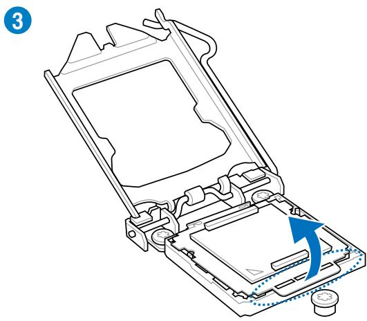
natural_image
Technical line drawing of a mechanical device with an arrow indicating rotation or movement (no text or symbols present)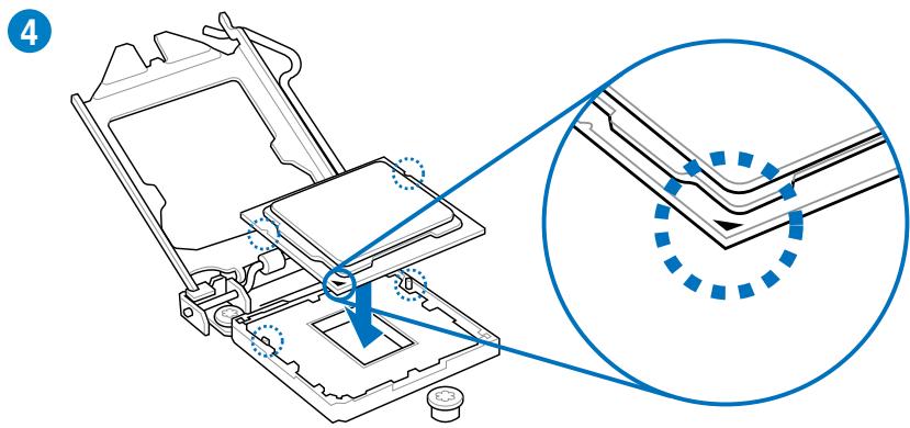
text_image
Technical diagram showing mechanical assembly with highlighted components and a magnified detail view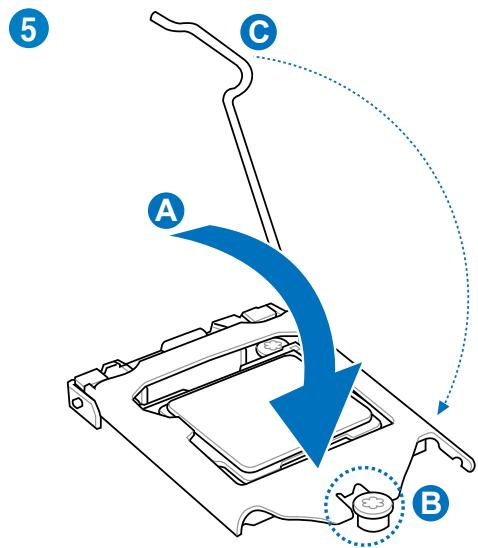
text_image
5 A C B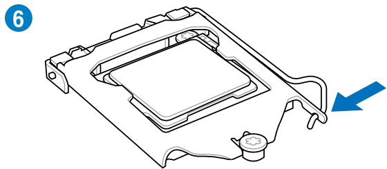
natural_image
Technical line drawing of a mechanical component with a blue arrow indicating direction (no text or symbols)natural_image
Technical line drawing of a mechanical assembly with a tool and blue components (no text or symbols)
text_image
2 CPU PAN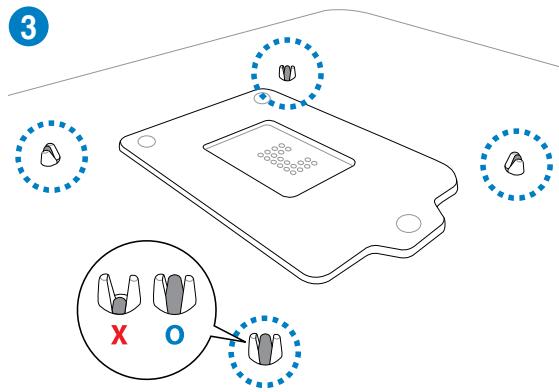
text_image
3 X Onatural_image
Diagram of a CPU fan with blue arrows indicating rotational speed, no text or symbols present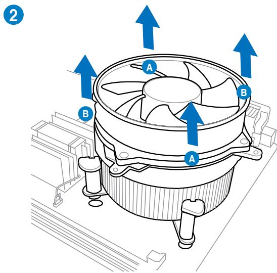
text_image
2 A B A Bnatural_image
Line drawing of a mechanical support structure with a blue arrow indicating rotation (no text or symbols)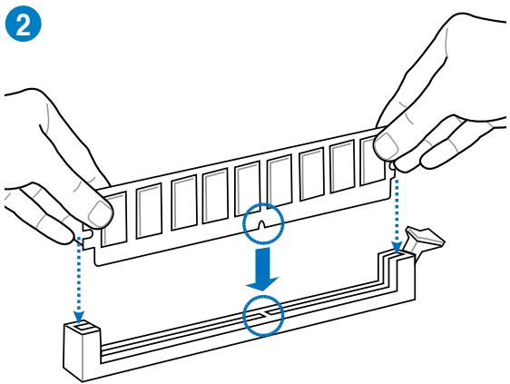
text_image
Diagram illustrating a mechanical assembly or mounting process with labeled components and directional arrows indicating movement.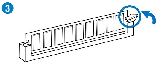
natural_image
Technical line drawing of a mechanical component with a circular arrow indicating rotation (no text or symbols)natural_image
Diagram of a computer RAM module with two labeled arrows (A and B) indicating directional movement, no text or symbols present.text_image
Diagram showing a computer RAM module with blue directional arrows indicating internal components, labeled with number 1.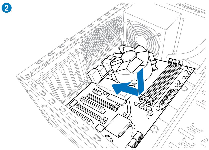
natural_image
Diagram of a computer motherboard showing CPU socket, fan, and drive mechanism (no text or labels)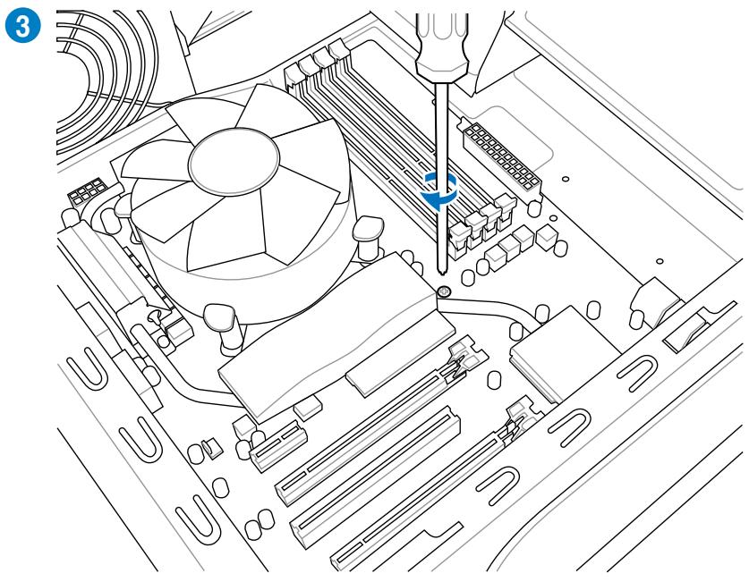
natural_image
Technical line drawing of a computer motherboard with CPU socket and screwdriver (no text or symbols)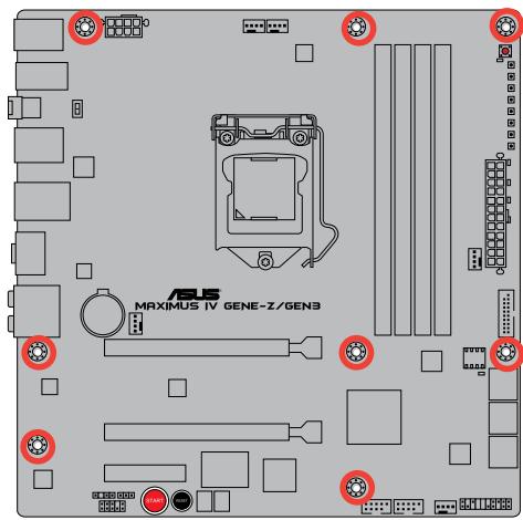
text_image
MAXIMUS IV GENE-Z/GEN3
text_image
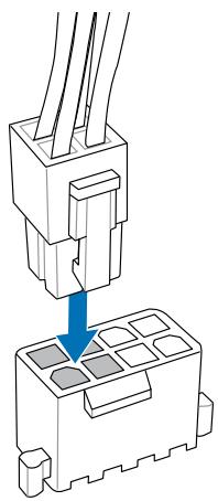
Diagram showing a component being inserted into a grid, with a blue arrow indicating the process.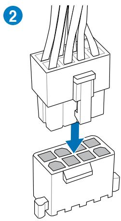
text_image
2OU
natural_image
Diagram of a connector assembly showing two pins inserted into a housing (no text or symbols present)OU
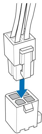
natural_image
Diagram of a connector assembly showing two parts with a blue arrow indicating a process (no text or symbols present)text_image
Diagram showing cable connection to a connector with labeled components and directional arrows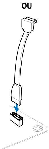
text_image
OUflowchart
graph TD
    A["IDE_LED+"] --> B["IDE_LED"]
    C["PWR Ground"] --> D["POWER SW"]
    E["Reset Ground"] --> F["RESET SW"]

text_image
IDE_LED POWER_SW RESET_SW IDE_LED+ IDE_LED- PWR Ground Reset GroundConnecteur USB
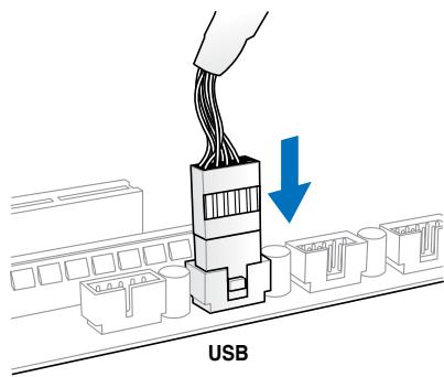
text_image
USBnatural_image
Diagram of a computer monitor internal structure showing ports, casing, and drive mechanism (no text or labels)natural_image
Diagram of a device panel with arrows indicating rotation and assembly (no text or symbols)natural_image
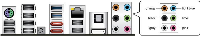
Diagram of a mechanical assembly with directional arrows indicating motion (no text or symbols)| Port | Headset2 canaux | 4 canaux | 6 canaux | 8 canaux |
| Bleu clair | Line In | Line In | Line In | Line In |
| Vert | Line Out | Front Speaker Out | Front Speaker Out | Front Speaker Out |
| Rose | Mic In | Mic In | Mic In | Mic In |
| Orange | - | - | Center/Subwoofer | Center/Subwoofer |
| Noir | - | Rear Speaker Out | Rear Speaker Out | Rear Speaker Out |
| Gris | - | - | - | Side Speaker Out |
Ports audio
text_image
orange light blue black lime gray pinknatural_image
Illustration of a microphone connected to a display unit with earphones and cables (no text or symbols)text_image
REPUBLIC OF GAMERS Advanced Mode Extreme Tuning Main Advanced Monitor Boot Tools LNC Node Enable Target CPU Turbo-Mode Temp: 300MHz Target User Temp: 100MHz CPU Level Up Auto Load Extreme OC Profile All Overclock Tuner Auto Turbo Ratio ALL Comps ... Maximum Turbo Ratio setting (Adjustable in 00) Auto Internal FLL Overvoltage Auto Memory Frequency AUTO Memory Bandwidth Booster Disinjnd FPU Power Saving Mode Disabled NEW Timing Control Change settings to suit Extreme Overclocking by selecting Yes.Select Screen
T8: Select Time Enter Direct +/- Change Out, P1: General Help P2: Previous Value P3: Utilized Defaults P40: Save ESC Exit P42: Print Screen Version 2.40.1201 Copyright © 2019 American networks, Inc. ASUStext_image
GPU:DSM Post CPU Performance Settings Digital-VAN-POWER Control Extreme DV CPU VOLTAGE 1.050V CPU Manual Voltage Auto ISPU Offset Node Sign ISPU Offset Voltage 1.050V Auto DVAV Voltage 1.050V Auto DVAV DATA REF Voltage on DHA Auto DVAV CTRL REF Voltage on DHA Auto DVAV DATA REF Voltage on CHB Auto RJN = 0.2900V Max = 0.8300V Standard = 0.5000V Decrease = 0.0050V >= : Raise/Reduce Select Screen T4: Select Tres Enter: Select >= : Change Opt. F1: General help F2: Previous Values F3: Optimized Defaults F4: Save ECG Exit F5: Print ScreenAllows you to manually adjust the Turbo CPU ratio.
[All Cores mode (Adjustabale in OS)]
[By number of active cores mode (Unadjustable in OS)]
Long Duration Maintained [Auto]
Short Duration Power Limit [Auto]
Additional Turbo Voltage [Auto]
CPU Core Current Limit [Auto]
CPU I/O Current Limit [Auto]
Vcore PWM mode [T.Probe]
iGPU Current Capability [100%]
Skew Driving Voltage [Auto]
CPU Spread Spectrum [Auto]
text_image
REPUBLIC OF GAMERS Advanced Mode Extrem Number With Advanced Monitor Boot Tools BDO Information BDO Version Build Date EC Version NE Version South Bridge Shopping CPU Information DOSI(R) Cure(TK) 15-2000 CPU @ 2.4GHz Stand NEW NET Memory Information Opti Memory Stand 2040 MB 1000 MB System Language English System Date System Time Screen Length: Administrator Security +1: Select Screen +2: Select Timms Enter's Select +/- Change Cut, +1: General Help +2: Previous Values +3: Outlined Defaults +4: Save ETC Exit +3: Print Screen Choose the system default language ASUS Version 2.40.1201 Copyright ©2019 American newstrnds, Inc.text_image
REPUBLIC OF GAMERS Advanced Mode Extrem: Number Main Advanced Monitor Boot Text BDO Main's Security > Password Description If ONLY the Administrator's password is set, then this only limits access to bring and is only asked for when entering setup. If ONLY the user's password is set, then this is a power or password and will be entered it boot or enter setup. In setup the user will have Administrator rights. Administrator Password User Password Not Installed Not Installed Administrator Password User Password To clear the administrator password, key in the current password in the Enter Current Password box, and then press (Enter) when prompted to create/confire the password. ##: Select Screen F1: Select Item Enter's Select +/- Change Out, F1: General Help F2: Previous Values F3: Utilized Defaults F4: Save ESC Exit F5: Print Screen ASUS Version 2-00.2013 Copyright © 2010 American Newsrends, Inc.![ASUS MAXIMUS IV GENE-Z GEN3 - CPU Spread Spectrum [Auto] - 1](/content/2020/04/113891/images/b06d971b35553c3d9d6d945335e3c0998fb20f1fd53c3f3bf7de4cb8b09c2abb.jpg)
text_image
REPUBLIC OF GAMERS Advanced Mode Extrem Breaker Main Advanced Monitor Boot Tool CPU Configuration System Agent Configuration PCR Configuration data Configuration USB Configuration Board Devices Configuration MPN IMG Configuration P00 Connect CPU Configuration Parameters ##: Select Screen F1: Select Time Enter Select +/- Change Dot, F1: General Help F2: Previous Value F3: Optimized Defaults F40: Save ESC: Exit F32: Print Screen Version 2.40.1201 Copyright © 2019 American reports, Inc. ASUS3.5.1 CPU Configuration (Configuration du CPU)
text_image
REPUBLIC OF GAMERS Advanced Mode Extracn Breaker Exit Advanced Monitor Boot Text Back Advanced's CPU Configuration 3 CPU Configuration INTL100 Cons I/O 15-2000 CPU @ 2.8GHz E64T Supported Processor Load 200V Max Processor Approving 20ms Altitude Revision 78 LT Cache: 255 KB LT Cache: 1024 KB LT Cache: 6144 KB Processor Cores: 4 Intel HT Technology Not Supported CPU Valid Rate: 16-28 CPU Current Ratio: 29 CPU Valid: 8.0% Intel Adaptive Thermal Monitor Enabled Active Processor Cores All Limit CPU Valid: Disabled Execute Disable Bit Enabled Intel Virtualization Technology DissuOLED Allows user can manually adjust the maximum non-harbo CPU ratio. The value will be limit to CPU case or factory setting. ##: Select Screen F1: Select Item Enteri Sprint +/- Change Out, F1: General Help F2: Previous Values F3: Optimized Defaults F4: Save FRC Exit F1: Print Screen Version 2.40.2011 Copyright ©2010 American Postrends, Inc. ASUStext_image
Enhanced Intel SpeedStep Technology Turbo Mode CPU CIE CPU CI Report CPU CI Report Package C State Limit Encaid Encaid Auto Auto Auto Auto No Limit Select Screen Select Item Options Select ✓/✓ Change Opt. F1: General Help F2: Previous Values F3: Optimized Defaults F4: Save ECG Exit F5: Print Screen Version 2.00.2011 Copyright 2019 American Hiathends, Inc.CPU Ratio [Auto]
Hyper-threading [Enabled]
text_image
REPUBLIC OF GAMERS Advanced Mode Extracr. Marker Exit Advanced Monitor Boot Text Back Advanced's System Agent Configuration > System Agent Configuration Initiate Graphic Adapter PCDE GPU Memory SRR Render Standby Enabled Set this line to Enabled: In execs Lucid Virtual GPU Multi-Monitor Enabled Select which graphics controller to use as the primary boot device. ##: Select Screen T1: Select Item Enter Direct +/- Change Out, F1: General Help F2: Previous Values F3: Outlined Defaults F40: Save FRC Exit F42: Print Screen ASUS Version 2.00.12VL Copyright (C) 2010 American Newsfriends, Inc.text_image
REPUBLIC OF CAMERA Advanced Mode Extrem: Number Main Advanced Monitor Boot Tool BDO Advanced's PCI Configuration > PCI Configuration High Precision Timer Enabled Enabled/Unadjusted the High Precision Event Timer. ##1: Select Screen F1: Select Time Enter Select +/- Change Dot, F1: General Help F0: Previous Value F0: Optimized Defaults F00: Save ESC Exit F321: PRINT SCREEN Version 2.40.1201 Copyright ©2019 American Reportnds, Inc. ASUStext_image
Hot Price Disabled F10 Save F10 Exit F10 Print Screen ASUS version 2.00.001 Copyright (c) 2010 American networks, Inc.SATA Mode (Mode SATA) [AHCI Mode]
text_image
REPUBLIC OF GAMERS Advanced Mode Extrem: Driver Main Advanced Monitor Boot Text BDO Advanced's USB Configuration > USB Configuration USB Devices: 2 Huts Legacy USB Support Enabled Legacy USB 3 Support Enabled HDI hard-off Disabled Enables Legacy USB support, AUTO option disables legacy support if no USB devices are connected, DISABLE option will keep USB devices available only for EFI applications.Select Screen
F1: Select Store Enter's Store +/- Change Out, F1: General Help F2: Previous Value F3: Utilized Defaults F40: Save ESC Exit F42: Print Screen Version 2.40.1201 Copyright © 2010 American Newsrends, Inc.
text_image
REPUBLIC OF GAMERS Advanced Mode Extracn Breaker Rin Advanced Monitor Boot Tool Back Advanced Onboard Devices Configuration > HD Audio Controller Enabled Front Panel Type HD SPOT Out Type SPOT JMB Storage Controller Enabled JMB Storage OFF+1 Enabled Display Options In POST Enabled Amodia USB 3.0 Controller Enabled Amodia USB 3.0 Battery Changing Support Disabled Intel B2579 LVM Enabled Intel B2579 FXE OFF+1 Disabled Enabled Enabled Enabled/Disassembled Altila HD Audio LED Select Screen F1: Select Item Enter Select +/- Change Cut, F1: General Help F2: Previous Values F3: Optimized Defaults F4: Save FDC Exit F2: Print Screen ASUS Version 2.40.1201, Copyright © 2010 American forecasts, Inc.text_image
REPUBLIC OF GAMERS Advanced Mode Exit Extreme Tension Main Advanced Monitor Boot Tools Back Advanced: AFR > EUP Ready Disabled Restore NC Power Loss Power On By PS/2 Keyboard Power On By PS/2 Mouse Power On By PCIE Power On By FSC Power Off Disabled Disabled Disabled Allow BDD to switch off some power at SS to get the system ready for EUP requirement. When not to be enabled, all other PMR options will be switched off. →1 Select Screen Till Select Time Enter Select +/-: Change Opt. F1: General Help F2: Previous Values PSI: Optimized Defaults F30: Save FSC: Exit F15: Print Screen © 2019 © 2019 © 2019 American Settings, Inc. ASUS version 2.00.1001. Copyright © 2019 American Settings, Inc.EuP Ready [Disabled]
[Disabled] Désactive la fonction EuP (Energy Using Products) Ready.
text_image
REFRUCO OF GAMERS Advanced Mode Extremed Marker Exit Advanced Monitor Boot Tools BDO Advanced's I200 Configuration > I200 Configuration I200 IP Number Information I200.1 BNumber I200 Timer Keeper Last State Current Operation Time: C Minute, 6 Hour, 8 Bag Total Operation Time: C Minute, 6 Hour, 8 Bag E: Select Screen F: Select Time Enter Select V:C Change Cut, P1: General Help P2: Previous Values P3: Default Defaults P40: Save ESC: Exit P42: Print Screen Version 2.40.1201. Copyright © 2019 American newstrnds. Cre. ASUSiROG Timer Keeper [Last State]
text_image
REPUBLIC OF GAMERS Advanced Mode Extinction: Tension Main Advanced Monitor Boot Test Back Advanced's R03 Connect > R03 Connect Enabled PC Faster mode StringROG Connect [Enabled]
RC Poster Mode (Mode ROG Poster) [String]
text_image
REFRUC OF GAMERS Advanced Mode Extrac Breaker Main Advanced Monitor Boot Text Anti Durable Support Enrolled Voltage Monitor Temperature Monitor Fan Speed Monitor Fan Speed Control If enabled, system will have 200 or on project function. ##: Select Screen F1: Select Time Enter Select +/- Change Out, F1: General Help F2: Previous Value F3: Optimized Defaults F4: Save ESC Exit F5: Print Screen Version 2.40.1201, Copyright ©2019 American resoners, Inc. ASUSAnti Surge Support (Support Anti Surge) [Enabled]
PCH Voltage; PCH Voltage; VCCSA/IO Voltage; CPU PLL Voltage; IGPU Voltage
CPU Temperature; MB Temperature [xxx°C/xxx°F]
CPU FAN; Chassis FAN1/2/3 Speed; CPU FAN OPT Speed [xxxxRPM] or [Ignored] / [N/A]
text_image
RESIDUC OF GAMERS Advanced Mode Extremer Marker Main Advanced Monitor Boot Text Backup Nullock State On Full Screen Logo Enrolled Wait For 7: If Error Enrolled Action ROM Messages Force Skills Setup Mode Advanced Mode Boot Option Priorities Boot Option #1 PS: ADC #0... Boot Option #2 IDA: OR SID... Hard Drive 3DS Priorities Network Device 3DS Priorities Reset Options PS: HOC MC3200/AKS-4VLSN0 IBM GE $25T 9008 V1006 Set the order of the legacy devices in this group.Select Screen
F1: Select Time Enter Select +/- Change Out, P1: General Help P2: Previous Value P3: Optimized Defaults P40: Save ESC Exit P42: Print Screen Version 2.40.1201 Copyright ©2010 American newspapers, Inc. ASUStext_image
RESPUBLIC OF GAMENS Advanced Mode Extrem: Newer Main Advanced Monitor Boot Text Back Tools A08B 0.C. Profile s B.C. Profile Configuration Setup Profile1 Status : No! Installed Setup Profile2 Status : No! Installed Setup Profile3 Status : No! Installed Setup Profile4 Status : No! Installed Setup Profile5 Status : No! Installed Setup Profile6 Status : No! Installed Setup Profile7 Status : No! Installed Setup Profile8 Status : No! Installed Add your CMOS Profile Label1 Save to Profile: Load From Profile: Input the label of setup profileSelect Screen
F1: Select Store Enter Select +/- Change Out, F1: General Help F2: Previous Value F3: Optimized Defaults F4: Save ESC Exit F32: Print Screen ASUS Version 2.40.1201 Copyright © 2019 American newstrands, Inc.
BCLK/PCIE Frequency; CPU Voltage; DRAM Voltage; VCCSA/IO Voltage; CPU PLL Voltage; PCH Voltage; CPU Ratio
text_image
Exit Load Optimized Defaults Save Changes & Reset Discard Changes & Exit ASUS EZ Mode Launch EFI Shell from filesystem deviceLoad Optimized Defaults
Discard Changes & Exit
Launch EFI Shell from filesystem device (Lancer l'application EFI Shell)
text_image
ASUS ESOS How do you want to download your USB. Options: USB2.0 (Read Internet) Download USB2.0 (Read Internet) Options: USB2.0 (Read Web) Options: USB2.0 (Read Web) USB2 (Recommended) Connected USB2 Model Receiver Accuracy & Options Sendline USB2 Release Date 12/18/2016 Next Help Cancel Update Options Recommendationtext_image
ASUS Smart Update iOS Smart Internet ASUS Windows 2021 (11/25/2020) MSU's new in the version 3. Mio-80% Next Next Current OSOS Music Name: Business To Science Services: Mio Release Time: 11/25/2020 Back Nexttext_image
ASUS Update Update ASUS Update Internet ASUS Update 2021 (11/05/2018) ASUS's last in this update 3. Intel-62% ASUS Update Current ASUS Music Name: Business To Science Services: ASUS Release Date: 11/15/2018 Back Next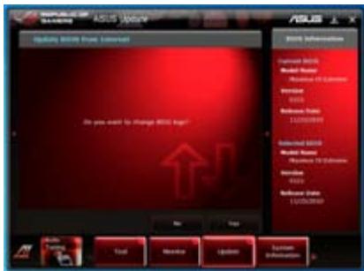
text_image
ASUS Award Award 2008 Award from Internet Do you want to change Award No Add Remove Update Options Information Certificate 2008 Model Name: Resource ID Calendar Intrain 12/05/2019 Database Date: 12/05/2019 Certificate 2008 Model Name: Resource ID Calendar Intrain 12/05/2019 Database Date: 12/05/2019 Add Remove Update Options Information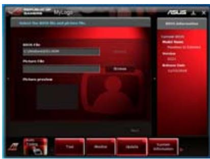
text_image
MyLogo Select the 2018 file and your new file. Microsoft File © Microsoft Internet Explorer Picture File Windows Picture profile ASUS Microsoft Office Internet Explorer Microsoft Windows Microsoft Azure Microsoft Azure Server Microsoft Azure Server Microsoft Azure Server Microsoft Azure Server Microsoft Azure Server Microsoft Azure Server Microsoft Azure Server Microsoft Azure Server Microsoft Azure Server Microsoft Azure Server Microsoft Azure Server Microsoft Azure Server Microsoft Azure Server Microsoft Azure Server Microsoft Azure Server Microsoft Azure Server Microsoft Azure Server Microsoft Azure Server Microsoft Azure Server Microsoft Azure Server Microsoft Azure Server Microsoft Azure Server Microsoft Azure Server Microsoft Azure Server Microsoft Azure Server Microsoft AzureServer Microsoft Azure Server Microsoft Azure Server Microsoft Azure Server Microsoft Azure Server Microsoft Azure Server Microsoft Azure Server Microsoft Azure Server Microsoft Azure Server Microsoft Azure Server Microsoft Azure Server Microsoft Azure Server Microsoft Azure Server Microsoft Azure Server Microsoft Azure Server Microsoft Azure Server Microsoft Azure Server Microsoft Azure Server Microsoft Azure Server Microsoft Azure Server Microsoft Azure Server Microsoft Azure Server Microsoft Azure Server Microsoft Azure Server Microsoft Azure Server Microsoft Azure server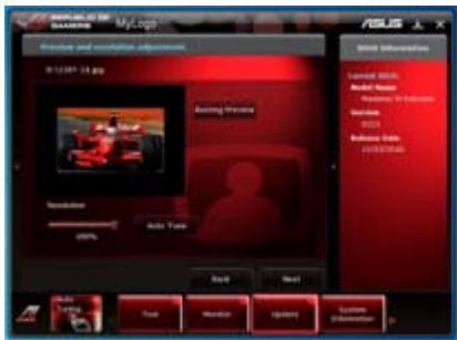
text_image
My Log My Log Video and audio adjustment 01:24:57 13.jpg Audio Preview Resolution Auto Temp Back Next USB Information Symbol 20.0% Audio Name Audio Size Indicator Vcc Vcc Indicate Mode FIRESTERStext_image
ASUS Update Update Update from No. Downloaded ASUS No. ©: 12/06/2018 Browse Back Next ASUS Update Language ASUS Model Name: Microsoft SQL Server Version: 2003 Database Data: LCPN-2018 Language ASUS Model Name: Microsoft SQL Server Version: 2003 Database Data: LCPN-2018 Back Next Task About Update Options Optionstext_image
MyLogo ASUS System needs to reboot for changes to take effect. Why you want to reboot? No Yes Hi/Hi/Hi/Hi/Hi/Hi/Hi/Hi/Hi/Hi/Hi/Hi/Hi/Hi/Hi/Hi/Hi/Hi/Hi/Hi/Hi/Hi/Hi/Hi/Hi/Hi/Hi/Hi/Hi/Hi/Hi/Hi/Hi/Hi/Hi/Hi/Hi/Hi/Hi/Hi/Hi/Hi/Hi/Hi/Hi/Hi/Hi/Hi/Hi/Hi/Hi 2008 Sub-System License: 3008 Model Name: Microsoft To Service Version: AutoCAD Database Tools COMPUTERtext_image
HOLI E2 Flash 2 utility v0.10 Flash Info ©DELL® Revius TV SENE-2 VSP1 SENS DATE: 04/19/2011 File Path: Drive Info F657 Folder Info 03/22/11 02:40p <2% 03/22/11 02:57p <2% 04/25/11 02:20p 8399648 04/26/11 05:04p <2% 04/26/11 05:05p <2% Trushes M6rap Revius TV CFNE-2 - AOS-0707, RM E65741 K43_K84_Serien_1X E65771 K45_K84_PMMN File Info ©DELL® VSP1 DATE: Help Info Enter Select or Load (Table Selection TopScan PopUp PageDown/Menu/Full Move Print Exit PSX Backup ASUStext_image
Please select boot device: SATA:XXXXXXXXXXXXXX USBXXXXXXXXXXXXXX UEFI:XXXXXXXXXXXXXX Enter Setup ↑ and ↓ to move selection ENTER to select boot device ESC to boot using defaultstext_image
ASUSTek BIOS Updater for DOS V1.18 [2010/04/29] Current ROM BOARD: MAXIMUS IV GENE-Z/GEN3 VER: 0208 DATE: 05/25/2011 Update ROM BOARD: Unknown VER: Unknown DATE: Unknown PATH: A:\ BIOS backup is done! Press any key to continue. Note Saving BIOS:Mise à jour du BIOS
text_image
ASUSTek BIOS Updater for DOS V1.18 [2010/04/29] Current ROM BOARD: MAXIMUS IV GENE-Z/GEN3 VER: 0208 DATE: 05/25/2011 Update ROM BOARD: Unknown VER: Unknown DATE: Unknown PATH: A:\ A: XXXXX.ROM 4194304 2010-08-05 17:30:48 Note [Enter] Select or Load [Tab] Switch [V] Drive Info [Up/Down/Home/End] Move [B] Backup [Esc] Exittext_image
Are you sure to update BIOS? Yes Notext_image
Microsoft 2003.dwg - A.Dwg-2 Source: Name: File Edit View Insert Help Browse Documents Notes Properties Video Computer Search Book 1 Search Book 2 SNETT Expense 1 BOSK Data 1 Book Document Settings Content/Tools MPTL Web A.Dwg-2 BOSK Data 1 Source: Edit Sub-View Edit Sub-View Edit Sub-View Edit Sub-View Edit Sub-View Edit Sub-View Edit Sub-View Edit Sub-View Edit Sub-View Edit Sub-View Edit Sub-View Edit Sub-View Edit Sub-View Edit Sub-View Edit Sub-View Edit Sub-View Edit Sub-View Edit Sub-View Edit Sub-View Edit Sub-View Edit Sub-View
text_image
REPUBLIC OF GAMERS DIGI+ VRM DIGI+ VRM Load-Sine Calibration 6% DIGI+ VRM CPU Current Capability 130% CPU PWM Frequency 7500Hz DIGI+ VRM Phase Control Standard Extreme DIGI+ VRM CPU Current Capability A higher value brings a wider total power range and extends the overdlacing frequency range simultaneously. DIGI+ VRM Duty Control T Probe Extreme ASUS ⊥ X 4 5 Auto Tuning Tool Monitor Update System Information Annule les modifications Applique les modifications1. DIGI+ VRM Load-line Calibration
text_image
ASUS NVIDIA GAVENS DIGI+ VRM Digi+ VRM Load-Size Calibration DIGI+ VRM CPU Current Protection CPU PWM Frequency P08112 DIGI+ VRM Phase Control Standard Extreme DIGI+ VRM Duty Control U Probe Extreme DIGI+ VRM Load-Size Calibration The voltage drop during CPU loading can be collected from 5% to 100% to improve overcooling stability. Power Saving Performance * The actual performance factor may depend on our CPU specifications. * Do not exceed the thermal mode in. The thermal condition should be improved. Auto Tuning Tool Monitor Update System Information2. DIGI+ VRM CPU Current Protection
text_image
ASUS COMPULIO OF BANERA DIGI+ VRM DIGI+ VRM Load Line Calibration 0% DIGI+ VRM CPU Current Protection CPU VRM Frequency 2580Hz DIGI+ VRM Phase Control Standard Extreme DIGI+ VRM Duty Control T-Reate Extreme DIGI+ VRM CPU Current Protection A higher value through a wider total power range and networks the superblocking frequency range simultaneously. Apply UIDS Auto Tuning Tool Monitor Update System Information3. CPU PWM Frequency
text_image
ASUS PRODUCES OF GIAWARE DISC1+ VRM DISC1+ VRM Load Size Calibration 0% DISC1+ VRM CPU Current Protection Disordered CPU PWM Frequency 25000Ω DISC1+ VRM Phase Control Standard Extreme DISC1+ VRM Duty Control T Probe Extreme CPU PWM Frequency Switching Frequencies will affect the VRM (current response and component thermal, higher frequency gate speed to current responses) Current I/Qency Increase SOC Range * Data from various semiconductor models that switching to Manual mode. The thermal sensitivity should be improved. Apply Under Auto Tuning Tool Monitor Update System Information4. DIGI+ VRM Phase Control
text_image
SIMULIS OF GAMERS DICI+ VRM Load-line Calibration DICI+ VRM Phase Control Standard Extronic DICI+ VRM Phase Control Phase number is the number of working VR phases. Choose full phase mode under helper system to pick up to sell more transport and better thermal performance. (1) Randomized Phase control based on CPU command. (2) Extension: Full phase mode CPU FRM Frequency 2548Hz Efficiency Performance 3. The extension of the thermal module has chosen to be necessary. The thermal condition should be removed. Apply Undo Auto Tuning Tool Monitor Update Systems Information5. DIGI+ VRM Duty Control
text_image
IEEE 5000 / GAMERS DIGI+ VRM Load Line Calibration DIGI+ VRM Phase Control Standard Extreme DIGI+ VRM Duty Control DIGI+ VRM Duty Control adjusts the number of many VM phase and the thermal of every phase component. (1) I-Phase: Thermal balance (2) Extreme: Current balance DIGI+ VRM CPU Current Protection 1.30% CPU PWM Frequency 2.00GHz DIGI+ VRM Duty Control 1. Pulse Extreme * By any service the thermal module, this Thermal condition is not available.
text_image
Warning 1. After processing batch, the audio starts performance testing and may reduce a 2.5x speed. The audio has indicated that the system is normally closed when they may appear after system events. These are the messages and switches the testing process. To obtain, there is no need to be normally closed the computer during the event. 2. The audio-based system performance comes with the installed messages as much as 10% and 30%. 3. The audio testing system reaches the highest levels of system settings, including the frequency and inflection of UPI and IUI, localization of advanced coding systems (recovables). 4. The audio testing settings will be closed in the system DOS and set back effect after the initial installation of automatic testing. 5. Audio being a order stress test. The sound might find using the test and will return to normal after the test completes. Start Canceltext_image
Auto Tuning Successful! CPU 3610 MI: ↑20% 100.3 x 36 GPU 1100 MI: ↑00% 20/08/1/13 OK4.3.4 EPU
Lancer Sensor Recorder
text_image
ASUS Voltage Temperature Fan Speed Battery Rate at low port to monitor the changes in the system's performance. (12) 0.0V (12) 0.0V (12) 0.0V (12) 0.0V (12) 0.0V (12) 0.0V (12) 0.0V (12) 0.0V (12) 0.0V (12) 0.0V (12) 0.0VFan Speed
text_image
ASUS Voltage Temperature Fan Speed History Record Allows you to record the changes in the system. ✓ Vccrs N/A V +12V N/A V ✓ +5V N/A V +3.2V N/A V Sensor View 0.000 V +12V 12.298 V +5V 5.080 V +3.5V 3.312 V Type Voltage Date 4/11/2011 Record interval 20 seconds Record duration 6 hours Start recording 00:34:00 00:35:00 (5/34:00) 05:37:00 05:38:00 X : P 100% Y : P 100% (T=0) Auto Tuning Tool Monitor Update System Informationtext_image
REPUBLIC OF GAMERS AI Charger+ ASUS ↓ Welcome to a new level in USB 3.0 fast-charging experience with the ASUS AI Charger+, a new and improved version of the unique and fast-charging software AI Charger*. With AI Charger+, you can now charge BC 1.1** standard mobile devices 3X*** faster than before aside from conveniently charging your iPhone, iPod, or iPad using it's easy and user-friendly interface. *ASUS AI Charger is a unique and fast-charging software that supports the iPhone, iPod, and iPad. **Contact the manufacturer of your USB mobile device to check if it supports the BC 1.1 function. ***Actual charging time may vary depending on the type, speed, and specifications of the USB device attached. Enable Disable 3X Speed Apply Auto Tuning Tool Monitor4.3.9 ROG CPU-Z
text_image
Stem TypeO25 Settings: Area 1 General SLATCM Computer SPC, Maxima in GENE E Dialal Efficiency Score 10.165 PSD Rate 1.4 Decade 1 Dialal Frequency 333 MHz Primary Design CalM Delay (Hz) 7 Maxim to LND Delay (MHz) 7 Maxim to Pulsar Speed (Pb) 7 Cycles Time (MHz) 88 Constant Rate (Hz) 1 Secondary Design CalM Delay (MHz) 4 Dialal Delay Cycle Time 59 Dialal Delay Insercic 1100 PRTS Delay (MHz) 0 RSD to RMS Rate (MHz) 4 PCLK/ACT RMS Time (MHz) 38 WMTs to HAD-CdB (MHz) 4 CAL General Power (kHz) 0 LSD/WR Mux (MHz) 0 Tertiary Design WAL/WDZ 1 WAL/WDZ 2 WAL/WDZ 3 WAL/WDZ 4 WAL/WDZ 5 WAL/WDZ 6 WAL/WDZ 7 WAL/WDZ 8 DRAM (Hz), I, J, K 0.1 DRAM (Hz), L, M, N 0.1 RCL Offset 14 Max Bound Trip Latency (Hz) 50 0.0 Named Trip Latency (Hz) 50 0.0 Apply OKtext_image
Stern Two(s) Settings General ACU-TAS Computer LLC, Proceding 21.0000 SPB Efficiency Score 10/161 PUB DUE 1.4 Diagram 1 TRIAB Frequency 571.4 Hz Primary Settings CALA Latency (LTL) 7 Rms to CALA Data (DRC) 8 Rms to Pulsatage (PSY) 9 Cycle Time (Rus) 10 Correspondance Rate (RS) 11 Secondary Settings Rms to Rms Latency (RMS) 8 Rms to Rms Cycle Time 20 Rms to Refract Time 4.63 RMTT Recovery Time (RMT) 8 READ to RMTT Cycle Time (RDT) 9 POSS FCF With Time (PSFF) 10 WINS to WINS Connection (WINS) 4 CNC External Power Vdc (CNC) 3 CALM Wide Latency (WNTL) 6 Secondary Settings NUMBER ANSIGNED 2 RANSER 3 WINDI 3 WINDO 4 NURORA 3 PAVVED 3 PANUCER 4 DRAM ID: 1 (A) 30 DINJID ID: 1 (B) 30 DRAM ID: 1 (C) 30 PUL Offset 14 Max Realized Trip Latency (A) 18 20 Realized Trip Latency (B) 18 20 20 30 Apply OK
text_image
Diagram showing server rack with icons and a highlighted button, likely illustrating a system or data transfer process.Utiliser RC Tweaklt
text_image
RC Poster Information: Standby Power In Poster Mode: String CodeRC Remote
text_image
RC Remote START RESET OK CancelRC Diagram
line
| Time (s) | Current (iV) | Voltage (V) | |----------|--------------|-------------| | 0 | 0 | 0 | | 1 | 0 | 0 | | 2 | 0 | 0 | | 3 | 0 | 0 | | 4 | 0 | 0 | | 5 | 0 | 0 | | 6 | 0 | 0 | | 7 | 0 | 0 | | 8 | 0 | 0 | | 9 | 0 | 0 | | 10 | 0 | 0 | | 11 | 0 | 0 | | 12 | 0 | 0 | | 13 | 0 | 0 | | 14 | 0 | 0 | | 15 | 0 | 0 | | 16 | 0 | 0 | | 17 | 0 | 0 | | 18 | 0 | 0 | | 19 | 0 | 0 | | 20 | 25 | 1.5 | | 21 | 25 | 1.5 | | 22 | 25 | 1.5 | | 23 | 25 | 1.5 | | 24 | 25 | 1.5 | | 25 | 25 | 1.5 | | 26 | 25 | 1.5 | | 27 | 25 | 1.5 | | 28 | 25 | 1.5 | | 29 | 25 | 1.5 | | 30 | 25 | 1.5 | | 31 | 25 | 1.5 | | 32 | 25 | 1.5 | | 33 | 25 | 1.5 | | 34 | 25 | 1.5 | | 35 | 25 | 1.5 | | 36 | 25 | 1.5 | | 37 | 25 | 1.5 | | 38 | 25 | 1.5 | | 39 | 25 | 1.5 | | 40 | 25 | 1.5 | | 41 | 25 | 1.5 | | 42 | 25 | 1.5 | | 43 | 25 | 1.5 | | 44 | 25 | 1.5 | | 45 | 25 | 1.5 | | 46 | 25 | 1.5 | | 47 | 25 | 1.5 | | 48 | 25 | 1.5 | | 49 | 25 | 1.5 | | 50 | 25 | 1.5 | | Note: The actual values for Current and Voltage are not provided in the code snippet, so they are represented as placeholders. You would need to run the code to get the actual values and labels on the chart.GPU Tweaklt
text_image
[ MAIN MENU ] 1. Create RAID Volume 2. Delete RAID Volume 3. Reset Disks to Non-RAID 4. Recovery Volume Options 5. Exit [ DISK/VOLUME INFORMATION ] RAID Volumes: None defined. Physical Devices: Port Device Model Serial # 0 ST3160812AS 9LS0HJA4 1 ST3160812AS 9LS0F4HL 2 ST3160812AS 3LS0JYL8 3 ST3160812AS 9LS0BJ5H Size Type/Status(Vol ID) 149.0GB Non-RAID Disk 149.0GB Non-RAID Disk 149.0GB Non-RAID Disk 149.0GB Non-RAID Disk [↑↓]-Select [ESC]-Exit [ENTER]-Select Menutext_image
[ CREATE VOLUME MENU ] Name: Volume0 RAID Level: RAID0 (Stripe) Disks: Select Disks Strip Size: 128KB Capacity: 0.0 GB Sync: N/A Create Volume [ HELP ] Enter a unique volume name that has no special characters and is 16 characters or less.text_image
[ SELECT DISKS ] Port Drive Model Serial # Size Status 0 ST3160812AS 9LS0HJA4 149.0GB Non-RAID Disk 1 ST3160812AS 9LS0F4HL 149.0GB Non-RAID Disk 2 ST3160812AS 3LS0JYL8 149.0GB Non-RAID Disk 3 ST3160812AS 9LS0BJ5H 149.0GB Non-RAID Disk Select 2 to 6 disks to use in creating the volume. [↑↓]-Prev/Next [SPACE]-SelectDisk [ENTER]-DoneWARNING: ALL DATA ON SELECTED DISKS WILL BE LOST. Are you sure you want to create this volume? (Y/N):
text_image
[ DELETE VOLUME MENU ] Name Level Drives Capacity Status Bootable Volume0 RAID0 (Stripe) 2 298.0GB Normal Yes [ HELP ] Deleting a volume will reset the disks to non-RAID. WARNING: ALL DISK DATA WILL BE DELETED. (This does not apply to Recovery volumes) [↑↓]-Select [ESC]-Previous Menu [DEL]-Delete Volumetext_image
[ DELETE VOLUME VERIFICATION ] ALL DATA IN THE VOLUME WILL BE LOST! (This does not apply to Recovery volumes) Are you sure you want to delete volume "Volume0"? (Y/N):text_image
[ CONFIRM EXIT ] Are you sure you want to exit? (Y/N):text_image
Smart Storage Clouding This is not a device to use any security or privacy. It is also used to ensure that this is useful for maintaining the cloudless security system.text_image
Enable Acceleration Select the 30-6 data drive you want to use to allocate your storage system. ● SSD on port 1:19 GB ○ SSD on port 2:14 GB Select the size allocated for the cache memory ○ 20 KB ● Full disk capacity (maximum 64 GB) Select the disk to volume to accelerate Volume0 (2KB GB) (system) ● Select the disk or volume for optimal system acceleration Select the macromotor mode ● Advanced mode ○ Maximized mode More help OK Canceltext_image
VDSL Smart Storage Technology Smart Storage Calling Application Status Accessories Accessories 3D Configuration 3D - 100% / 100% Accessories Accessories Accessories Accessories Accessories Accessories Accessories Accessories Accessories Accessories Accessories Accessories Accessories Accessories Accessories Accessories Accessories Accessories Accessories Accessories Accessories Accessories Accessories Accessories Accessories Accessories Accessories Accessories Accessories Accessories Accessories Accessories Accessories Accessories VDSL
text_image
Open Explore Search... Play Date Play Network Drive ... Download Network Drive... Create Software Depts Rename Properties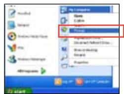
text_image
Enter Computer Close Close Close Save Save As... Save As... Save As... Save As... Save As... Add Programs Add Programs Add Programs Add Programs Add Programs Add Programs Add Programs Add Programs Add Programs Add Programs Add Programs Add Programs Add Programs Add Programs Add Programs Add Programs Add Programs Add Programs Add Programs Add Programs Add Programs Add Programs Add Programs Add Programs Add Programs Add Programs Add Programs Add Programs Add Programs Add Programs Add Programs Add Programs Add Programs Add Programs All Programs All Programs All Programs All Programs All Programs All Programs All Programs All Programs All Programs All Programs All Programs All Programs All Programs All Programs All Programs All Programs All Programs All Programs All Programs All Programs All Programs All Programs All Programs All Programs All Programs All Programs All Programs All Programs All Programs All Programs All Programs All Programs All Programs All Programou
text_image
Windows Windows cannot open the file: File: tsetep.com To open this file, Windows needs to know what program created it. Windows can go online to look it up automatically, or you can manually select from a list of programs on your computer. What do you want to do? Use the Web service to find the appropriate program Select the program from a list OK Canceltext_image
Open With Choose the program you want to use to open this file: File: trtsetup.com Programs Recommended Programs: Notepad Other Programs: Adobe Reader 8.1 Internet Explorer Paint Windows Media Player Windows Picture and Fax Viewer WordPad Type a description that you want to use for this kind of file: Always use the selected program to open this kind of file Browse... If the program you want is not in the list or on your computer, you can look for the appropriate program on the Web. OK Canceltechnologies multi-GPU
5.1 Technologie ATI® CrossFireX™
natural_image
Close-up of a computer motherboard with visible CPU socket, RAM slots, and a highlighted drive (no text or symbols)natural_image
Close-up of a computer motherboard with visible CPU socket and connectors (no text or symbols)text_image
ATI Catalyst Control Center Setup ATI Catalyst™ to use 50% performance opening solution that will offer the following settings: follows the ATI Catalyst™ configuration method. You can adjust your configuration suitable. ATI catalyst features controls which will offer you completely useful quality performance and reach 50% settings on all applications. Configuration: Please select one of the following. Custom Control Center Advanced Area Use default settings OK Cancel SetActiver la technologie CrossFireX™
natural_image
Computer motherboard with CPU socket and monitor, no visible text or symbolstext_image
Appearance and Recommendation Search Change viewing time Add to the GPS Personalization appearance and sounds. Windows (Windows) and Appearance Change the user's sound and use of your own screen. Database Settings Change from website background of yellow or orange file for your own software to download the desktop. Browse Search Change your own server or adjust what it displays. It covers your own version or configuration that is used in the Web interface. It provides your own database. Default Change which audio commands when you do nothing from getting a new or using your local file. Visual Options Push a filter mask packet, you can also change how the music format works with different audio and listening. Frames Change the video frames. That can change a copy range of audio and audio elements on the right side of the video frame. This is also important for more audio, music, and audio features. The video frame will be replaced by the original image. Share Selection Adjust your own audio format, which changes the video as a copy of more than 50% on this screen. It is also important for more audio features.text_image
Display Settings Monitor Drag the items to match your monitors. Identify Monitors 1 3 4 2 1. Generic Prof Monitor on NVIDIA Server 8000 GTS This is very much monitor Based the desktop onto this monitor Resolution: Low High Colors: Highest (32 bit) $520 by 2,990 pixels How do I get the best display? Advanced Settings... OK Cancel Helptext_image
Genova, PrIP Monitor and NVIDIA GeForce 8600 GT3 Properties Adapter Monitor Color Management GeForce 8600 GT3 Looking for the NVIDIA Display Control Panel? All of the NVIDIA control panels have been consolidated into a single application. The NVIDIA Control Panel. It can be launched from the Windows Control Panel or by right-clicking on the Windows desktop. Start the NVIDIA Control Panel OK Cancel Applytext_image
Manage 3D Settings This is the existing and creating an existing software project. The existing will be used to create a new product that is currently being installed. I should change from the following settings: New Settings - Create Settings Settings Primary Primary Setting Primary Sub-Section Primary Sub-Section Primary Sub-Section Primary Sub-Section Primary Sub-Section Primary Sub-Section Primary Sub-Section Primary Sub-Section Primary Sub-Section Primary Sub-Section Primary Sub-Section Primary Sub-Section Primary Sub-Section Primary Sub-Section Primary Sub-Section Primary Sub-Section Primary Sub-Section Primary Sub-Section Primary Sub-Section Primary Sub-Section Primary Sub-Part Primary Sub-Part Primary Sub-Part Primary Sub-Part Primary Sub-Part Primary Sub-Part Primary Sub-Part Primary Sub-Part Primary Sub-Part Primary Sub-Part Primary Sub-Part Primary Sub-Part Primary Sub-Part Primary Sub-Part Primary Sub-Part Primary Sub-Part Primary Sub-Part Primary Sub-Part Primary Sub-Part Primary Sub-Part Primary Sub-Component Primary Sub-Component Primary Sub-Component Primary Sub-Component Primary Sub-Component Primary Sub-Component Primary Sub-Component Primary Sub-Component Primary Sub-Component Primary Sub-Component Primary Sub-Component Primary Sub-Component Primary Sub-Component Primary Sub-Component Primary Sub-Component Primary Sub-Component Primary Sub-Component Primary Sub-Component Primary Sub-Component Primary Sub-Component Primary Sub-Components Primary Sub-Components Primary Sub-Components Primary Sub-Components Primary Sub-Components Primary Sub-Components Primary Sub-Components Primary Sub-Components Primary Sub-Components Primary Sub-Components Primary Sub-Components Primary Sub-Components Primary Sub-Components Primary Sub-Components Primary Sub-Components Primary Sub-Components Primary Sub-Components Primary Sub-Components Primary Sub-Components Primary Sub-Components Primary Sub-Component Primary Sub-Component Primary Sub-Component Primary Sub-Component Primary Sub-Component Primary Sub-Component Primary Sub-Component Primary Sub-Component Primary Sub-Component Primary Sub-Component Primary Sub-Component Primary Sub-Component Primary Sub-Component Primary Sub-Component Primary Sub-Component Primary Sub-Component Primary Sub-Component Primary Sub-Component Primary Sub-Component Primary Sub-PrincipalActiver la configuration SLI
text_image
Set SLI Configuration Set SLI Configuration For any other system (e.g. or any other system) to be installed in the main system, it is not available. 1. Use the SLI configuration for your systems. 2. Use the SLI device to install a single device. 3. Use the SLI device to install a multi-device device. 4. Use the SLI device to install a single device. Description: • Use the SLI device to install a single device into the existing software of the system • Use the SLI device to install a multi-device device into the existing software of the system System Information OK Cancel5.3 Technologie LucidLogix® Virtu™
text_image
Open control panel Enable Virtu Remove from system traytext_image
Open control panel Disable Virtu Remove from system tray
EC Declaration of Conformity
We, the undersigned,

| Manufacturer: | ASUSTek COMPUTER INC. |
| Address, City: | No. 150, LI-TE RD., PEITOU, TAIPEI 112, TAIWAN R.O.C. |
| Country: | TAIWAN |
| Authorized representative in Europe: | ASUS COMPUTER GmbH |
| Address, City: | HARKORT STR. 21-23, 40880 RATINGEN |
| Country: | GERMANY |
Responsible Party Name: Asus Computer International
Address: 800 Corporate Way, Fremont, CA 94539.
Phone/Fax No: (510)739-3777/(510)608-4555
[Non-Text]
hereby declares that the product
Product Name : Motherboard
Model Number : MAXIMUS IV GENE-Z/GEN3
Conforms to the following specifications:
☒ FCC Part 15, Subpart B, Unintentional Radiators
□ FCC Part 15, Subpart C, Intentional Radiators
□ FCC Part 15, Subpart E, Intentional Radiators
Supplementary Information:
This device complies with part 15 of the FCC Rules. Operation is subject to the following two conditions: (1) This device may not cause harmful interference, and (2) this device must accept any interference received, including interference that may cause undesired operation.
Representative Person's Name: Steve Chang / President

Signature :
Position: CEO Name: Jerry Shen
(EC conformity marking)

CE marking