
CG 24EBSP(SL) - Lawn mower HiKOKI - Free user manual and instructions
Find the device manual for free CG 24EBSP(SL) HiKOKI in PDF.


| Product Type | Grass Trimmer / Brush Cutter |
| Brand | HiKOKI |
| Model | CG 24EBSP (SL) |
| Engine Displacement | 23.9 cm³ |
| Engine Type | 2-stroke, air-cooled |
| Max Engine Output | 0.8 kW |
| Fuel Tank Capacity | 520 cm³ (0.52 L) |
| Fuel Mixture Ratio | 25:1 to 50:1 (gasoline:2-stroke oil) |
| Dry Weight | 5.0 kg |
| Cutting Attachment | Nylon line trimmer head (semi-auto feed) |
| Nylon Line Diameter | 2.4 mm |
| Nylon Line Length (per spool) | 4 m |
| Recommended Cutting Line Length | 11–14 cm per side |
| Idle Speed | 2800–3200 min⁻¹ |
| Max Output Shaft Speed | 7600 min⁻¹ |
| Sound Pressure Level (LpA) | 99 dB(A) |
| Guaranteed Sound Power Level (LwA) | 111 dB(A) |
| Vibration Level (front/left handle) | 5.6 m/s² |
| Vibration Level (rear/right handle) | 4.0 m/s² |
| Spark Plug | NGK BMR7A (gap: 0.6 mm) |
| Safety Features | Harness, barrier bar, cutting attachment guard, anti-vibration system, ignition stop switch |
| Included Accessories | Harness, barrier bar, combo box spanner, hex bar wrench, blade cover (if equipped) |
Frequently Asked Questions - CG 24EBSP(SL) HiKOKI
User questions about CG 24EBSP(SL) HiKOKI
0 question about this device. Answer the ones you know or ask your own.
Ask a new question about this device
Download the instructions for your Lawn mower in PDF format for free! Find your manual CG 24EBSP(SL) - HiKOKI and take your electronic device back in hand. On this page are published all the documents necessary for the use of your device. CG 24EBSP(SL) by HiKOKI.
USER MANUAL CG 24EBSP(SL) HiKOKI
natural_image
Technical line drawing of a mechanical clamp or tool with a base, labeled 'CG24EBSP (SL)' at the bottom (no other text or symbols)
Read the manual carefully before operating this machine.
natural_image
Diagram of two cylindrical electronic components with internal connectors, no text or symbols present


natural_image
Technical line drawing of a mechanical assembly with no visible text or symbols
12 13 14

natural_image
Diagram of a device handle with arrows indicating direction (no text or symbols)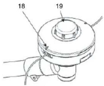
natural_image
Diagram of a device's rear panel with arrows indicating direction (no text or symbols)
natural_image
Diagram of a car head panel with three upward arrows indicating top-down components (no text or symbols present)15 16

natural_image
Diagram of a handheld device with a cylindrical component inserted, showing a downward arrow indicating force or movement (no text or symbols present)
natural_image
Technical line drawing of a mechanical component with a central hub and cable (no text or symbols)17 18 19


20 21 22

natural_image
Line drawing of a hand adjusting a mechanical component with a circular dial (no text or symbols)

natural_image
Line drawing of a person wearing a helmet and safety harness (no text or symbols)
natural_image
Line drawing of a person wearing a helmet and safety harness, holding a device with arrows indicating motion (no text or symbols)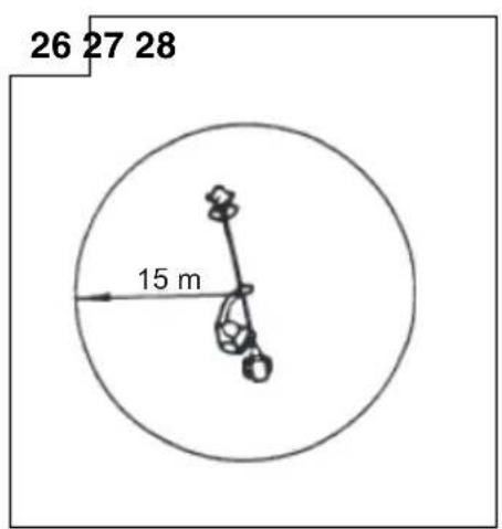



natural_image
Technical line drawing of a mechanical device with internal components and a valve (no text or symbols)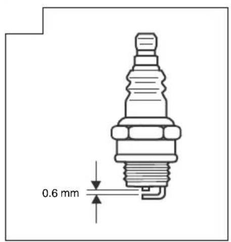





MEANINGS OF SYMBOLS
NOTE: Some units do not carry them.
| Symbols⚠ WARNINGThe following show symbols used for the machine. Be sure that you understand their meaning before use. | |||
 | It is important that you read, fully understand and observe the following safety precautions and warnings. Careless or improper use of the unit may cause serious or fatal injury. |  | Ignition stop |
 | Read, understand and follow all warnings and instructions in this manual and on the unit. |  | Fuel and oil mixture |
 | Always wear eye, head and ear protectors when using this unit. |  | Idle speed adjustment |
 | Do not use metal/rigid blades when this sign is shown on the unit. |  | Priming pump |
 | Keep all children, bystanders and helpers 15 m away from the unit. If anyone approaches you, stop the engine and cutting attachment immediately. |  | Guaranteed Sound power level |
 | Be careful of thrown objects. |  | Hot Surface – Contact with hot surface can cause serious burns. |
 | Shows maximum shaft speed. Do not use the cutting attachment whose max rpm is below the shaft rpm. |  | The hedge trimmer attachment cannot be used on models with this label. |
 | Gloves should be worn when necessary, e.g., when assembling cutting equipment. |  | Blade thrust may occur when the spinning blade contacts a solid object in the critical area. A dangerous reaction may occur causing the entire unit and operator to be thrust violently. This reaction is called blade thrust. As a result, the operator may lose control of the unit which may cause serious or fatal injury. Blade thrust is more likely to occur in areas where it is difficult to see the material to be cut. |
 | Use anti-slip and sturdy footwear. | ||
 | Choke - Run position (Open) | ||
 | Choke - Start position (Closed) |  | Indicate handle location. Arrows which show limits for handle positioning. |
| Before using your machine• Read the manual carefully.• Check that the cutting equipment is correctly assembled and adjusted.• Start the unit and check the carburetor adjustment. See “MAINTENANCE”. | |||
Contents
WHAT IS WHAT ....7
WARNINGS AND SAFETY INSTRUCTIONS 8
SPECIFICATIONS 9
ASSEMBLY PROCEDURES 10
OPERATING PROCEDURES 11
MAINTENANCE....12
TROUBLESHOOTING....15
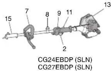
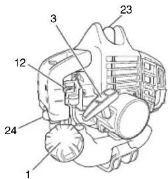
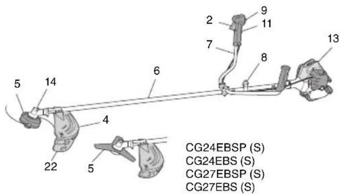
WHAT IS WHAT
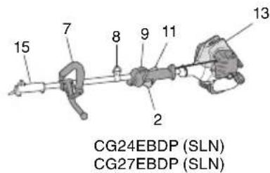
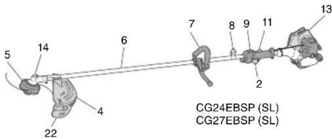
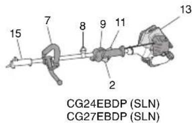
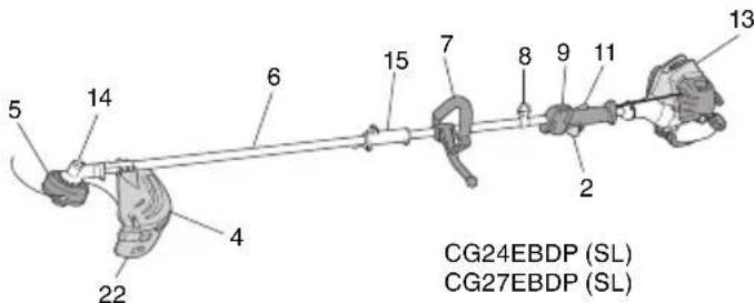
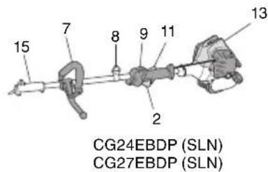
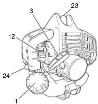
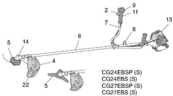
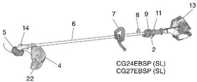
Since this manual covers several models, there may be some difference between pictures and your unit. Use the instructions that apply to your unit.
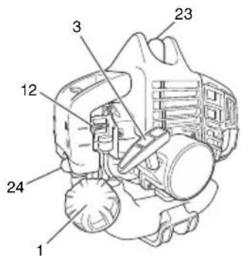
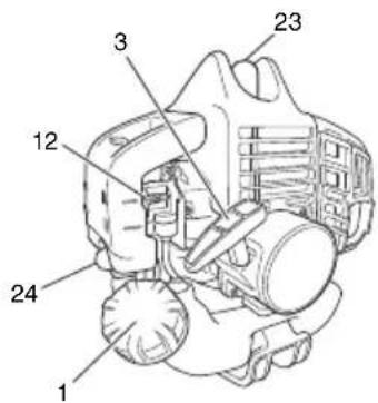
- Fuel cap
- Throttle trigger
- Starter handle
- Cutting attachment guard
- Cutting attachment
- Drive shaft tube
- Ha ndle
- Suspension eyelet
- Ignition switch
- Harness
- Throttle trigger lockout
- Choke lever
- Engine
- Angle transmission
- Joint case
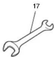
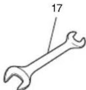
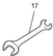
- Combi box spanner
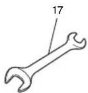
- Spanner (if so equipped)
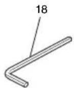
- Hex bar wrench
- Blade cover (if so equipped)
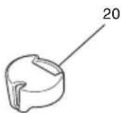
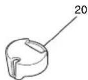
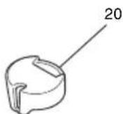
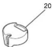
- Swivel cap
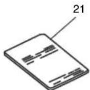
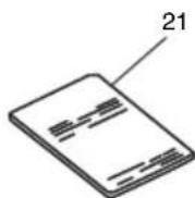
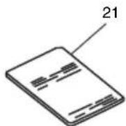
- Handling instructions
- Guard extension
- Spark plug
- Priming bulb

natural_image
Line drawing of a mechanical bracket or clamp (no text or symbols)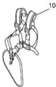
natural_image
Technical line drawing of a mechanical clamp or bracket assembly (no text or symbols)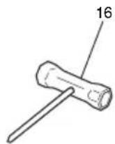




WARNINGS AND SAFETY INSTRUCTIONS
Operator safety
○ Always wear a safety face shield or goggles.
○ Always wear heavy, long pants and non-slip boots and gloves. Do not wear loose clothing, jewelry, short pants, sandals or go barefoot. Secure hair so it is above shoulder length.
○ Do not operate this tool when you are tired, ill or under the influence of alcohol, drugs or medication.
☐ Do not operate the tool at night or under bad weather conditions when visibility is poor. And do not operate the tool when it is raining or right after it has been raining.
Working on slippery ground could lead to an accide lose your balance.
○ Never let a child or inexperienced person operate the machine.
○ Long-term exposure to noise can result in permanent hearing impairment. Wear approved hearing protection. Pay attention to your surroundings. Be aware of any bystanders who may be signaling a problem. Remove safety equipment immediately upon shutting off engine.
○ Wear head protection.
Never start or run the engine inside a closed room or building. Breathing exhaust fumes can kill.
○ Keep handles free of oil and fuel.
○ Keep hands away from cutting equipment.
○ Do not grab or hold the unit by the cutting equipment.
○ Gloves should be worn when installing or removing the cutting attachment. Failure to do so may result in injury.
When the unit is turned off, make sure the cutting attachment has stopped before the unit is set down.
When operation is prolonged, take a break from time to time so that you may avoid possible Hand-Arm Vibration Syndrome (HAVS) which is caused by vibration.
WARNING
○ Antivibration systems do not guarantee that you will not sustain Hand-Arm Vibration Syndrome or carpal tunnel syndrome. Therefore, continual and regular users should monitor closely the condition of their hands and fingers. If any symptoms of the above appear, seek medical advice immediately.
☐ If you are using any medical electric/electronic devices such as a pacemaker, consult your physician as well as the device manufacturer prior to operating any power equipment.
Unit/machine safety
☐ Inspect the entire unit/machine before each use. Replace damaged parts. Check for fuel leaks and make sure all fasteners are in place and securely tightened.
○ Replace parts that are cracked, chipped or damaged in any way before using the unit/machine. Faulty parts may increase the risk of accidents and may lead to an injury.
○ Make sure the safety guard is properly attached.
○ Keep others away when making carburetor adjustments.
○ Use only accessories as recommended for this unit/machine by the manufacturer.
WARNING
☐ Never modify the unit/machine in any way. Do not use your unit/machine for any job except that for which it is intended.
○ Tampering with the engine voids the EU type approval of this engine.
○ Non-authorized modifications and/or accessories may result in serious personal injury or the death of the operator or others.
Fuel safety
○ Mix and pour fuel outdoors and where there are no sparks or flames.
○ Use a container approved for fuel.
○ Do not smoke or allow smoking near fuel or the unit/machine or while using the unit/machine.
○ Wipe up all fuel spills before starting engine.
○ Move at least 3 m away from fueling site before starting engine.
○ Stop engine before removing fuel cap.
Empty the fuel tank before storing the unit/machine. It is recommended that the fuel be emptied after each use. If fuel is left in the tank, store so fuel will not leak.
○ Store unit/machine and fuel in area where fuel vapors cannot reach sparks or open flames from water heaters, electric motors or switches, furnaces. etc.
WARNING
Fuel is easy to ignite or get explosion or inhale fumes, so that pay special attention when handling or filling fuel.
Cutting safety
○ Do not cut any material other than grass and brush.
○ Inspect the area to be cut before each use. Remove objects which can be thrown or become entangled.
○ For respiratory protection, wear an aerosol protection mask when cutting the grass after insecticide is scattered.
Keep others including children, animals, bystanders and helpers outside the 15 m hazard zone. Stop the engine immediately if you are approached.
○ Always keep the engine on the right side of your body.
○ Hold the unit/machine firmly with both hands.
Keep firm footing and balance. Do not over-reach. Losing your balance during work may lead to an injury.
Keep all parts of your body away from the muffler and cutting attachment when the engine is running.
○ Keep cutting attachment below knee level.
○ When relocating to a new work area, be sure to shut off the machine and ensure that all cutting attachments are stopped.
○ Never place the machine on the ground when running.
Always ensure that the engine is shut off and any cutting attachments have completely stopped before clearing debris or removing grass from the cutting attachment.
○ Always carry a first-aid kit when operating any power equipment.
Never start or run the engine inside a closed room or building and/or near inflammable liquids. Breathing exhaust fumes can kill.
☐ If the tool is operating poorly and produces strange noise or vibrations, turn off the engine immediately and ask your dealer to have it inspected and repaired.
Continued use under these conditions could lead to injury or tool damage.
○ Use in accordance with local laws and regulations.
Maintenance safety
○ Maintain the unit/machine according to recommended procedures.
○ Disconnect the spark plug before performing maintenance except for carburetor adjustments.
○ Keep others away when making carburetor adjustments.
○ Use only genuine HiKOKI replacement parts as recommended by the manufacturer.
Transport and storage
○ Carry the unit/machine by hand with the engine stopped and the muffler away from your body.
○ Allow the engine to cool, empty the fuel tank before storing or transporting.
Secure the machine during transport to prevent loss of fuel, damage or injury.
Empty the fuel tank before storing the unit/machine. It is recommended that the fuel be emptied after each use. If fuel is left in the tank, store so fuel will not leak.
○ Store unit/machine out of the reach of children.
○ Clean and maintain the unit carefully and store it in a dry place.
○ Make sure engine switch is off when transporting or storing.
○ When transporting and storing, cover blade with blade cover.
☐ You have to secure the machine during transport to prevent loss of fuel, damage or injury.
If situations occur which are not covered in this manual, take care and use common sense. Contact HiKOKI Authorized Service Centers if you need assistance. Pay special attention to statements preceded by the following words:
WARNING
Indicates a strong possibility of severe personal injury or loss of life, if instructions are not followed.
CAUTION
Indicates a possibility of personal injury or equipment damage, if instructions are not followed.
NOTE
Helpful information for correct function and use.
CAUTION
Do not disassemble the recoil starter. You may get a possibility of personal injury with recoil spring.
SPECIFICATIONS
| Model | CG24EBSP CG24EBS CG24EBDP | |||||||
| (SL) (S) (S) (SL) (SLN) | ||||||||
| Engine Displacement (cm3) Spark plug Idling speed (min-1) Speed of output shaft (min-1) Max. engine output (kW) | 23.9 NGK BMR7A 2800 - 3200 7600 0.8 | 23.9 NGK BMR7A 2800 - 3200 7600 0.8 | 23.9 NGK BMR7A 2800 - 3200 7600 0.8 | 23.9 NGK BMR7A 2800 - 3200 7600 0.8 | 23.9 NGK BMR7A 2800 - 3200 7600 0.8 | |||
| Fuel tank capacity (cm 3) | 520 | |||||||
| Dry weight (kg) 5.0 5.2 5.2 5.1 5.1 5.3 4.4 | ||||||||
| Cutting attachment | Type / Dia. (mm) | Nylon cord | Nylon cord | Metal blade (255) | Nylon cord | Metal blade (255) | Nylon cord | — |
| Sound pressure level LpA (dB (A)) | (ISO22868) Equivalent* Uncertainty | 99 3 | 99 3 | 96 3 | 99 3 | 96 3 | 99 3 | 99 3 |
| Measured sound power level LwA (dB (A)) | (2000/14/EC) Racing | 108 | 108 | 105 | 108 | 105 | 108 | — |
| Guaranteed sound power level LwA (dB (A)) | (2000/14/EC) Racing | 111 | 111 | 108 | 111 | 108 | 111 | — |
| Vibration level (m/s 2) (ISO22867) | ||||||||
| Equivalent (Front / Left handle)* Equivalent (Rear / Right handle)* Uncertainty | 5.6 4.0 2.0 | 3.9 2.7 1.2 | 3.1 2.8 1.2 | 3.9 2.7 1.2 | 3.1 2.8 1.2 | 6.2 3.4 2.0 | — — — | |
| Model | CG27EBSP CG27EBS CG27EBDP | ||||||
| (SL) (S) (S) (SL) (SLN) | |||||||
| Engine Displacement ( cm^3 ) Spark plug Idling speed ( min^-1 ) No load speed of output shaft ( min^-1 ) Max. engine output (kW) | 26.9 NGK BMR7A 2800 - 3200 7600 0.9 | 26.9 NGK BMR7A 2800 - 3200 7600 0.9 | 26.9 NGK BMR7A 2800 - 3200 7600 0.9 | 26.9 NGK BMR7A 2800 - 3200 7600 0.9 | 26.9 NGK BMR7A 2800 - 3200 7600 0.9 | ||
| Fuel tank capacity ( cm^3 ) | 520 | ||||||
| Dry weight (kg) 5.2 5.4 5.4 5.3 5.3 5.4 | 4.5 | ||||||
| Cutting attachment Type / Dia. (mm) | Nylon cord | Nylon cord | Metal blade (255) | Nylon cord | Metal blade (255) | Nylon cord | — |
| Sound pressure level LpA (dB (A)) (ISO22868) Equivalent* Uncertainty | 99 3 | 99 3 | 97 3 | 99 3 | 97 3 | 99 3 | 99 3 |
| Measured sound power level LwA (dB (A)) (2000/14/EC) Racing | 108 | 108 | 108 | 108 | 108 | 108 | — |
| Guaranteed sound power level LwA (dB (A)) (2000/14/EC) Racing | 111 | 111 | 111 | 111 | 111 | 111 | — |
| Vibration level (m/s2) (ISO22867) Equivalent (Front / Left handle)* Equivalent (Rear / Right handle)* Uncertainty | 6.7 4.1 2.0 | 4.1 3.0 1.2 | 3.7 2.6 1.2 | 4.1 3.0 1.2 | 3.7 2.6 1.2 | 5.3 3.4 2.0 | — — — |
NOTE
Equivalent noise level/vibration level are calculated as the time-weighted energy total for noise/vibration levels under various working conditions with the following time distribution:
* 1/2 Idle, 1/2 racing.
All data subject to change without notice.
ASSEMBLY PROCEDURES
Drive shaft to engine (Fig. 1)
Loosen tube locking bolt (1) about ten turns so that the bolt point will not obstruct drive shaft tube to be inserted. When inserting drive shaft tube, hold the tube locking bolt outward preventing inside flitting from obstructing as well.
Insert the drive shaft into the clutch case of the engine properly until the marked position (2) on the drive shaft tube meets the clutch case.
Some models may come with the drive shaft already installed.
NOTE
When it is hard to insert drive shaft up to the marked position on the drive shaft tube, turn drive shaft by the cutter mounting end clockwise or counter-clockwise. Tighten tube locking bolt lining up the hole in the shaft tube. Then tighten clamp bolt securely.
Installation of attachment (EBDP model only)
- Join the attachment in place of it.
- Make sure the lock pin (3) fits in the location hole (4) of tube and that the tube will not come off. (Fig. 2)
- Tighten the knob nut (5) securely. (Fig. 2)
Installation of handle
(1) Loop handle type ((SL),(SLN) model)
WARNING
Always use a barrier bar (6) and shoulder harness with the loop handle. (Fig. 3)
Attach the handle to the drive shaft tube with the angle towards the engine.
Adjust the location to the most comfortable position before operation.
NOTE
If your unit has handle location label on drive shaft tube, follow the illustration.
(2) Bike handle type ((S) model)
Remove the handle bracket (7) from the assembly. (Fig. 4)
Place the handles and attach the handle bracket with four bolts lightly. Adjust to appropriate position. Then attach it firmly with the bolts.
Attach the protection tube to the drive shaft or handle using cord clamps (8). (Fig. 5)
Throttle wire / stop cord
Press the upper tab (9) and open the air cleaner cover. (Fig. 6) Connect stop cords. (Fig. 7)
If the throttle outer end (10) is threaded on your unit, screw it and the earth terminal (11) (if so equipped) into the cable adjuster stay (12) all the way, and then tighten this cable end using the adjuster nut (13) against the cable adjuster stay (12).
Connect throttle wire end (14) to carburetor (15) and install swivel cap (16) (if so equipped) where is included in tool bag, onto swivel (15) (Fig. 8).
Press the upper tab (9) and close the air cleaner cover. (Fig. 6) Store stop cords (17) into the air cleaner cover. (Fig. 9)
Some models may come with the parts installed.
Installation of cutting attachment guard (Fig. 10 - 12)
NOTE
The guard bracket may come already mounted to the gear case on some models.
Install the cutting attachment guard on drive shaft tube against angle transmission. Tighten the guard bracket firmly so that the cutting attachment guard does not swing or move down during operation.
Install the cutting attachment guard to the guard bracket, which also secures the guard to the gear case using the two guard mounting screws.

WARNING
If an incorrect or faulty guard is fitted, this may cause serious personal injury.
CAUTION
Some cutting attachment guards are equipped with sharp line limiters. Be careful with handling it.
When using a trimmer head with two piece type cutting attachment guard, attach the guard extension to the cutting attachment guard. (Fig. 11)
NOTE
When attaching the guard extension to the cutting attachment guard, the sharp line limiter must be removed from the cutting attachment guard, (if so installed).
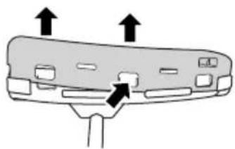
To remove the guard extension, refer to the drawings. Wear gloves as the extension has a sharp line limiter, then push the three square tabs on the guard one by one in order. (Fig. 12)
Installation of cutting attachment

WARNING
Install the cutting attachment properly and securely as instructed in the handling instructions. If not attached properly or securely, it may come off and cause serious and/or fatal injury.
Installation of semi-auto cutting head
1. Function
Automatically feeds more nylon cutting line when it is tapped at low rpm (not greater than 4500 min ^-1 ).
Specifications
| Code No. | Type of attaching screw | Direction of rotation | Size of attaching screw |
| 6696454 | Female screw Co | Counterclockwise M10 | xP1.25-LH |
| 6698639 |
Applicable nylon cord
Cord diameter: 2.4 mm Length: 4 m
2. Precautions
○ The case must be securely attached to the cover.
○ Check the cover, case and other components for cracks or other damage.
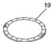
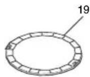
☐ Check the case and button for wear. If the wear limit mark (18) on the case is no longer visible or there is a hole in the bottom (19) of the button, change the new parts immediately. (Fig. 13)
○ The cutting head must be securely mounted to the unit's gear case.
☐ For outstanding performance and reliability, always use HiKOKI nylon cutting line. Never use wire or other materials that could become a dangerous projectile.
If the cutting head does not feed cutting line properly, check that the nylon line and all components are properly installed. Contact HiKOKI Authorized Service Centers if you need assistance.
3. Installation (Fig. 14)
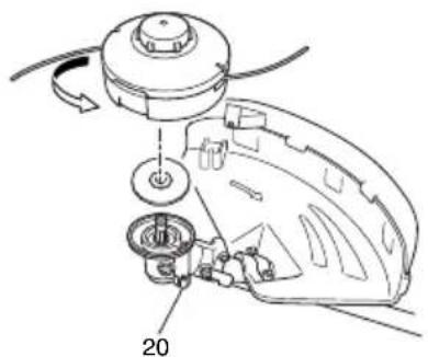
○ Install cutting head on gear case of grass trimmers/brush cutters. The mounting nut is left-hand-threaded. Turn clockwise to loosen/counterclockwise to tighten.
NOTE
○ Since the cutter holder cap is not used here, keep it for when a metal blade is used, if so equipped.
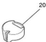
○ Press the stopper pin (20) of the gear case in order to lock the cutter holder.
4. Adjusting line length
○ Set the engine speed as low as possible and tap the head on the ground. The nylon line will be drawn out about 3 cm with each tap. (Fig. 15)
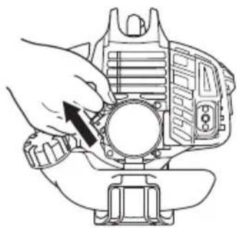
Also, you can extend the nylon line by hand but the engine must be completely stopped. (Fig. 16)
○ Adjust the nylon line to the proper length of 11–14 cm before each operation.
Installation of cutting blade (Fig. 17)
(If so equipped)
When installing a cutting blade, make sure that there are no cracks or any damage in it and that the cutting edges are facing the correct direction.
NOTE
○ When installing cutter holder cap (21), be sure to set concave side upward.
Press the stopper pin (20) of the angle transmission in order to lock the cutter holder (22). Please note that the cutter fixing bolt or nut (23) has left-handed threads, (clockwise to loosen/counter-clockwise to tighten). Tighten the fixing bolt or nut with the box wrench. [Tightening torque: 12 - 16 N·m]
CAUTION
Before operation, make sure the blade has been properly installed.
☐ If your unit is equipped with protection cover unit blade, check it for wear or cracks before operation. If any damage or wear is found, replace it, as it is an article of consumption.
○ You have to wear gloves when handling the cutting blade.
WARNING
For HiKOKI heads, use only flexible, non-metallic line recommended by the manufacturer. Never use wire or wire ropes. They can break off and become a dangerous projectile.
OPERATING PROCEDURES
Fuel (Fig. 18)
WARNING
☐ The trimmer is equipped with a two-stroke engine. Always run the engine on fuel, which is mixed with oil.
Provide good ventilation, when fueling or handling fuel.
☐ Fuel contains highly flammable and it is possible to get the serious personal injury when inhaling or spilling on your body. Always pay attention when handling fuel. Always have good ventilation when handling fuel inside building.
Fuel
○ Always use branded 89 octane unleaded gasoline.
Use genuine two-cycle oil or use a mix between 25:1 to 50:1, please consult the oil bottle for the ratio or HiKOKI Authorized Service Centers.
☐ If genuine oil is not available, use an anti-oxidant added quality oil expressly labeled for air-cooled 2-cycle engine use (JASO FC GRADE OIL or ISO EGC GRADE). Do not use BIA or TCW (2-stroke water-cooling type) mixed oil.
○ Never use multi-grade oil (10 W/30) or waste oil.
○ Always mix fuel and oil in a separate clean container.
Always start by filing half the amount of fuel, which is to be used. Then add the whole amount of oil. Mix (shake) the fuel mixture. Add the remaining amount of fuel.
Mix (shake) the fuel-mix thoroughly before filling the fuel tank.
Fueling
WARNING
○ Always shut off the engine before refueling.
○ Slowly open the fuel tank, when filling up with fuel, so that possible over-pressure disappears.
○ Tighten the fuel cap carefully, after fueling.
○ Always move the trimmer at least 3 m from the fueling area before starting.
○ Always wash any spilled fuel from clothing immediately with soap.
○ Be sure to check for any fuel leakage after refueling.
Before fueling, clean the tank cap area carefully no dirt falls into the tank. Make sure that the fuel is well mixed by shaking the container, before fueling.
Starting
CAUTION
Before starting, make sure the cutting attachment does not touch anything.
- Set ignition switch (24) to forward away from stop position. (Fig. 19)
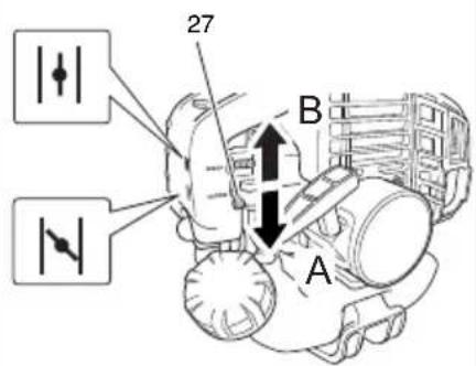
* Push priming bulb (25) about ten times so that fuel flows into carburetor. (Fig. 20) - Set choke lever (27) to START position (closed) (A) (Fig. 21)
- Pull recoil starter briskly, taking care to keep the handle in your grasp and not allowing it to snap back. (Fig. 22)
- When you hear the engine want to start, return choke lever to RUN position (open) (B). Then pull recoil starter briskly again.
NOTE
If engine does not start, repeat procedures from 2 to 4.
- Then allow the engine about 2–3 minutes to warm up before subjecting it to any load.
- Check that the cutting attachment does not rotate when the engine is idling.
Cutting (Fig. 23 - 26)
When cutting, operate engine at over 6500 min ^1 . Extended time of use at low rpm may wear out the clutch prematurely.
○ Cut grass from right to left.
○ Blade thrust may occur when the spinning blade contacts a solid object in the critical area.
A dangerous reaction may occur causing the entire unit and operator to be thrust violently. This reaction thrust. As a result, the operator may lose control of the unit which may cause serious or fatal injury. Blade thrust is more likely to occur in areas where it is difficult to see the material to be cut.
☐ Wear the harness as shown in the figure (if so equipped). The blade turns counter-clockwise, therefore, be advised to operate the unit from right to left for efficient cutting. Keep onlookers out of working area at least 15 m.
○ Use in accordance with local laws and regulations.
NOTE
Press the quick release button or pull emergency release flap (If so equipped) in the event of emergency. (Fig. 25)
WARNING
If cutting attachment should strike against stones or other debris, stop the engine and make sure that the attachment and related parts are undamaged. When grass or vines wrap around attachment, stop engine and attachment and remove them.
Stopping (Fig. 27)
Decrease engine speed and run at an idle for a few minutes, then turn off ignition switch (24).
WARNING
A cutting attachment can injure while it continues to spin after the engine is stopped or power control is released. When the unit is turned off, make sure the cutting attachment has stopped before the unit is set down.
Semi-auto cutting head
When cutting, operate engine at over 6500 min ^-1 . Extended time of use at low rpm may wear out the clutch prematurely.
○ Cut grass from right to left.
WARNING
A cutting attachment can injure while it continues to spin after the engine is stopped or power control is released. When the unit is turned off, make sure the cutting attachment has stopped, it becomes the unit is set down.
Automatically feeds more nylon cutting line when it is tapped at low rpm (not greater than 4500 min ^-1 ).
MAINTENANCE
MAINTENANCE, REPLACEMENT OR REPAIR OF THE EMISSION CONTROL DEVICES AND SYSTEMS MAY BE PERFORMED BY ANY NON-ROAD ENGINE REPAIR ESTABLISHMENT OR INDIVIDUAL.
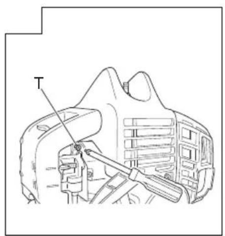
Carburetor adjustment (Fig. 28)
WARNING
○ The cutting attachment may be spinning during carburetor adjustments.
Never start the engine without the complete clutch cover and tube assembled! Otherwise the clutch can come loose and cause personal injuries.
In the carburetor, fuel is mixed with air. When the engine is test run at the factory, the carburetor is basically adjusted. A further adjustment may be required, according to climate and altitude. The carburetor has one adjustment possibility:
T = Idle speed adjustment screw.
Idle speed adjustment (T)
Check that the air filter is clean. When the idle speed is correct, the cutting attachment will not rotate. If adjustment is required, close (clockwise) the T-screw, with the engine running, until the cutting attachment starts to rotate. Open (counter-clockwise) the screw until the cutting attachment stops. You have reached the correct idle speed when the engine runs smoothly in all positions well below the rpm when the cutting attachment starts to rotate. n is called blade
If the cutting attachment still rotates after idle speed adjustment, contact HiKOKI Authorized Service Centers.
NOTE
Standard Idle rpm is 2800 - 3200 min -1.

WARNING
When the engine is idling the cutting attachment must under no circumstances rotate.
Air fi Iter (Fig. 29)
The air filter must be cleaned from dust and dirt in order to avoid:
○ Carburetor malfunctions
○ Starting problems
○ Engine power reduction
○ Unnecessary wear on the engine parts
○ Abnormal fuel consumption
Clean the air filter daily or more often if working in exceptionally dusty areas.
Cleaning the air fi Iter
Open the air filter cover and the filter (28). Rinse it in warm soap suds. Check that the filter is dry before reassembly. An air filter that has been used for some time cannot be cleaned completely. Therefore, it must regularly be replaced with a new one. A damaged filter must always be replaced.
Fuel fi Iter (Fig. 30)
Drain all fuel from fuel tank and pull fuel filter line from tank. Pull filter element out of holder assembly and rinse element in warm water with detergent.
Rinse thoroughly until all traces of detergent are eliminated. Squeeze, do not wring, away excess water and allow element to air dry.
NOTE
If element is hard due to excessive dirt buildup, replace it.
Spark plug (Fig. 31)
The spark plug condition is influenced by:
○ An incorrect carburetor setting
○ Wrong fuel mixture (too much oil in the gasoline)
○ A dirty air fi Iter
○ Hard running conditions (such as cold weather)
These factors cause deposits on the spark plug electrodes, which may result in malfunction and starting difficulties. If the engine is low on power, difficult to start or runs poorly at idling speed, always check the spark plug first. If the spark plug is dirty, clean it and check the electrode gap. Re-adjust if necessary. The correct gap is 0.6 mm. The spark plug should be replaced after about 100 operation hours or earlier if the electrodes are badly eroded.
NOTE
In some areas, local law requires using a resistor spark plug to suppress ignition signals. If this machine was originally equipped with resistor spark plug, use same type of spark plug for replacement.
Angle transmission (Fig. 32)
Check angle transmission or angle gear for grease level about every 50 hours of operation by removing the grease filler plug on the side of angle transmission.
If no grease can be seen on the flanks of the gears, fill the transmission with quality lithium based multipurpose grease up to 3/4. Do not completely fill the transmission.
Semi-auto cutting head
Nylon line replacement
(1) Remove the case (29) by firmly pushing inward the locking tabs with your thumbs as shown in Fig. 33.
(2) After removing the case, take out the reel and discard the remaining line.
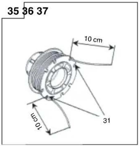
(3) Fold the new nylon line unevenly in half as shown in picture. Hook the U-shaped end of the nylon line into the groove (30) on the center partition of the reel.
One side of the cord should be about 10 cm longer than other side.
Wind both halves of the line on the reel in the same directic keeping each half of the line on its own side of the partition. (Fig. 34)
(4) Push each line into the stopper holes (31), leaving the loose ends approx. 10 cm in length. (Fig. 35)
(5) Insert both loose ends of the line through the cord guide (32) when placing the reel in the case. (Fig. 36)
NOTE
When placing a reel in the case, try to line up the stopper holes (31) with the cord guide (32) for easier line release later.
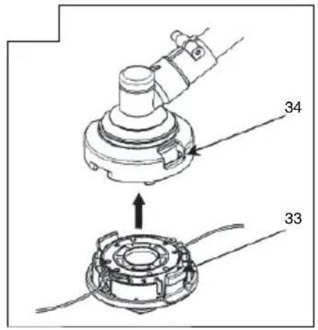
(6) Place the cover over the case so that the cap locking tabs (33) on the case meet the long holes (34) on the cover. Then push the case securely until it clicks into place. (Fig. 37)
(7) The initial cutting line length should be approx. 11–14 cm and should be equal on both sides. (Fig. 38)
Blade (Fig. 39)

WARNING
Wear protective gloves when handling or performing maintenance on the blade.
○ Use a sharp blade. A dull blade is more likely to snag and thrust. Replace the fastening nut if it is damaged and hard to tighten.
○ When replacing blade, purchase one recommended by HiKOKI, with a 25.4 mm (one inch) ft tting hole.
○ In the case of a 3 tooth blade (35), it can be used on either side.
○ Use the correct blade for the type of work
○ When replacing blades, use appropriate tools.
When cutting edges become dull, re-sharpen or file as shown in the illustration. Incorrect sharpening may cause excessive vibration.
○ Discard blades that are bent, warped, cracked, broken or damaged in any way.
NOTE
When sharpening blade it is important to maintain an original shape of radius at the base of the tooth to avoid cracking.
Maintenance schedule
Below you will find some general maintenance instructions. For further information please contact HiKOKI Authorized Service Centers.
Daily maintenance
○ Clean the exterior of the unit.
○ Check that the harness is undamaged.
○ Check the cutting attachment guard for damage or cracks. Change the guard in case of impacts or cracks.
☐ Check that the cutting attachment is properly centred, sharp, and without cracks. An off-centre cutting attachment induces heavy vibrations that may damage the unit.
○ Check that the cutting attachment nut is sufficiently tightened.
○ Make sure that the blade transport guard is undamaged and that it can be securely fitted.
○ Check that nuts and screws are sufficiently tightened.
○ Check that the unit is undamaged and free of defects.
Weekly maintenance
○ Check the starter, especially the cord and return spring.
○ Clean the exterior of the spark plug.
○ Remove it and check the electrode gap. Adjust it to 0.6 mm, or change the spark plug.
○ Check that the angle gear is filled with grease up to 3/4.
○ Clean the air filter.
Monthly maintenance
○ Rinse the fuel tank with gasoline.
○ Clean the exterior of the carburetor and the space around it.
○ Clean the fan and the space around it.
List of recommended accessories
| Type Name | Specifi cation LOOP HANDLE | BIKE HANDLE MULTI PURPOSE | ||||||||
| Diameter | Feed System Adapter or No. of Teeth (Blade) | Blade Thickness (mm) or Trimmer line Diameter (mm) | CG24EBSP (SL) | CG27EBSP (SL) | CG24EBS (S), CG24EBSP (S) | CG27EBS (S), CG27EBSP (S) | CG24EBDP (SL) | CG27EBDP (SL) | ||
| ALUMINUM HEADS | NYLON HEAD CH-100 (W/NYLON LINE) | 4" Pre-Cut Line 2.2 - 3.0 | ● | ● | ● | ● | ● | ● | ||
| NYLON HEAD CH-100 | ● | ● | ● | ● | ● | ● | ||||
| NYLON HEAD CH-300 (W/CUTTER HOLDER CAP) | 5" | Manual line feed | 2.2 - 2.7 | ● | ● | ● | ||||
| NYLON HEAD CH-300 | ● | ● | ● | |||||||
| TAP & GO NYLON HEADS | NYLON HEAD BF-5 | 5" | LM10 x 1.25 Nut LM8 x 1.25 | 2.2 - 3.0 ● | ● | ● | ● | ● | ● | |
| BLADES | BLADE B3/10/2.0 | 10" 3 2.0 ● | ||||||||
| BLADE B3/12/3.0 | 12" 3 3.0 ● | |||||||||
| BLADE B4/9/1.6 | 9" 4 1.6 ● ● | |||||||||
| BLADE B4/10/1.6 | 10" 4 1.6 ● ● | |||||||||
TROUBLESHOOTING
Use the inspections in the table below if the tool does not operate normally. If this does not remedy the problem, consult your dealer or the HiKOKI Authorized Service Center.
| Condition Cause Remedy | |||
| Engine does not start | Fuel system | Fuel tank is empty or fuel level is low | Fill the fuel tank with the correct fuel mix (25:1-50:1) |
| Fuel tank contains old fuel (offensive odor) | Replace with new fuel | ||
| Too much fuel is absorbed and spark plug is wet | 1. Disconnect the spark plug and allow to dry2. Pull the starter handle 5 or 6 times to remove the surplus fuel3. Attach the spark plug4. Set the choke lever to RUN position and pull the starter handle | ||
| Fuel filter is clogged with dirt | Clean the fuel filter | ||
| Fuel pipe is bent or disconnected | Ensure that the fuel flows smoothly | ||
| Carburetor malfunction Contact HiKOKI Authorized Service Centers | |||
| Electrical system | Stop switch lead has short-circuited Contact HiKOKI Authorized Service Centers | ||
| Spark plug is dirty Replace or clean the spark plug | |||
| Electrode gap is too big Adjust the gap to 0.6mm | |||
| Poor connection between high tension cable and spark plug | Reconnect | ||
| Electrical system malfunction Contact HiKOKI Authorized Service Centers | |||
| Other | Muffler exhaust port is clogged with carbon | Contact HiKOKI Authorized Service Centers for repair | |
| Engine starts but cuts out straightawayEngine is apt to cut out | Fuel system | Fuel tank is empty or fuel level is low | Fill the fuel tank with the correct fuel mix (25:1-50:1) |
| Fuel tank contains old fuel (offensive odor) | Replace with new fuel | ||
| Two-cycle oil has not been added | Contact HiKOKI Authorized Service Centers | ||
| Choke lever is in START position | Set the choke lever to RUN position | ||
| Air has got into fuel system | Reconnect the fuel pipe or joint | ||
| Carburetor malfunction Contact HiKOKI Authorized Service Centers | |||
| Electrical system | Ignition failure | ||
| Spark plug failure | Replace with new spark plug | ||
| Electrical system failure | Contact HiKOKI Authorized Service Centers | ||
| Other | Engine overheating | ||
| Wrong spark plug model | Replace with designated partSee “SPECIFICATIONS” | ||
| Dirty air cleaner | Clean | ||
| Carbon clogging (muffler exhaust port) | Clean | ||
| Insufficient compression (piston, piston ring, cylinder) | Contact HiKOKI Authorized Service Centers | ||
| Abnormal vibration | Cutting attachment is not properly installed | See “Installation of cutting attachment” | |
| Handle, handle bracket or other fastening part is loose | Check and tighten | ||
| Blade is bent or damaged | Replace with new blade | ||
| Grass is wrapped round gear case | Remove grass | ||
| Engine is running but blade does not moveMovement is poor | Grass is wrapped round gear case | Remove grass and dirt | |
| Engine does not stop | Stop switch failure | Set the choke lever to START position to stop the engineCease use immediately and contact HiKOKI Authorized Service Centers | |
| Engine stops when throttle is closed | Idle speed is too low | Contact HiKOKI Authorized Service Centers | |
| Blade continues rotating when throttle is closed | Idle speed is too highThrottle wire is too taut | Contact HiKOKI Authorized Service Centers | |
SYMBOLBEDEUTUNGEN
natural_image
Line drawing of a mechanical component with labeled part 10 (no text or symbols beyond label)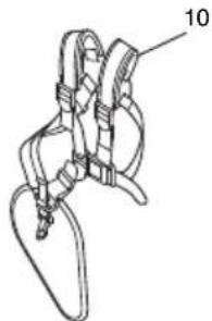
natural_image
Technical line drawing of a mechanical clamping device with labeled part 10 (no text or symbols beyond label)




natural_image
Simple line drawing of a mechanical bracket or clamp (no text or symbols)
natural_image
Technical line drawing of a mechanical clamping device with labeled part 10 (no text or symbols beyond label)


natural_image
Line drawing of a mechanical bracket with labeled part 10 (no text or symbols beyond label)
natural_image
Technical line drawing of a mechanical device with labeled part '10' (no text or symbols beyond label)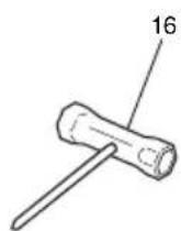





natural_image
Technical line drawing of a mechanical bracket or clamp (no text or symbols)
natural_image
Technical line drawing of a mechanical clamp or bracket assembly (no text or symbols)




FIGYELMEZTETÉSEK ÉS BIZTONSÁGI ÓVINTÉZKEDÉSEK
natural_image
Line drawing of a mechanical clamp or bracket with labeled part '10' (no text or symbols beyond label)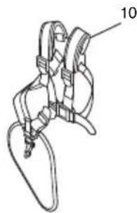
natural_image
Technical line drawing of a mechanical device with labeled part 10 (no text or symbols beyond label)





VAROVÁNÍ A BEZPEČNOSTNÍ POKYNY
Bezpečnost obsluhy
natural_image
Line drawing of a mechanical component with labeled part 10 (no text or symbols on the object itself)
natural_image
Technical line drawing of a mechanical clamping device with labeled part 10 (no text or symbols beyond label)




natural_image
Line drawing of a mechanical bracket or clamp (no text or symbols)
natural_image
Technical line drawing of a mechanical clamping device with labeled part 10 (no text or symbols beyond label)




AVERTISMENTE ŞI INSTRUCTIUNI DE SIGURANTĂ
natural_image
Line drawing of a mechanical bracket with labeled part 10 (no text or symbols beyond label)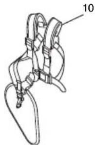
natural_image
Technical line drawing of a mechanical clamping device with labeled part 10 (no text or symbols beyond label)




OPOZORILA IN VARNOSTNA NAVODILA
Varnost upravljavca
natural_image
Technical line drawing of a mechanical component with labeled part 10 (no text or symbols beyond label)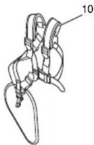
natural_image
Technical line drawing of a mechanical clamp or bracket assembly (no text or symbols)






VÝSTRAHY A BEZPEČNOSTNÉ POKYNY
Bezpečnost' obsluhy

CG 24EBSP (SL), CG 24EBSP (S)

CG 24EBSP (SL), CG 24EBSP (S), CG 24EBS (S)
CG 24EBDP (SL), CG 24EBDP (SLN)

CG 24EBDP (SL), CG 24EBDP (SLN)
CG 24EBS (S)

CG 27EBS (S)
CG 27EBSP (SL), CG 27EBSP (S), CG 27EBDP (SL), CG 27EBDP (SLN)


CG 27EBSP (SL), CG 27EBSP (S)
CG 27EBSP (SL), CG 27EBSP (S), CG 27EBS (S)
CG 27EBDP (SL), CG 27EBDP (SLN)

CG 27EBDP (SL), CG 27EBDP (SLN)CG 27EBS (S)


natural_image
Line drawing of a quill pen in an inkwell (no text or symbols)
natural_image
Line drawing of a quill pen in an inkwell (no text or symbols)
natural_image
Line drawing of a quill pen in an inkwell (no text or symbols)| English Polski | ||
| EC DECLARATION OF CONFORMITYWe declare under our sole responsibility that Grass Trimmer / Brush Cutter, identified by type and specific identification code *1), is in conformity with all relevant requirements of the directives *2) and standards *3). Technical file at *4) – See below.The European Standard Manager at the representative office in Europe is authorized to compile the technical fi le.Annex V (2000/14/EC): For information relating to noise emissions, see the chapter specifi cations.The declaration is applicable to the product affi xed CE marking. | DEKLARACJA ZGODNOŚCI Z WEOświadczamy na własną wyłączną odpowiedzialność, że podkaszarka/kosa spalinowa podanego typu i oznaczona unikalnym kodem identyfikacyjnym *1) jest zgodna z wszystkimi właściwymi wymogami dyrektyw *2) i norm *3). Dokumentacja techniczna w *4) – Patrz poniżej.Menedżer Norm Europejskich przedstawicielstwa firmy w Europie jest upoważniony do sporządzania dokumentacji technicznej.Załącznik V (2000/14/WE): Informacje na temat poziomu hałasu znajdują się w części Specyfikacje.Niniejsza deklaracja ma zastosowanie do produktu opatrzonego znakiem CE. | |
| Deutsch MagyarEG-KONFORMITÄTSERKLÄRUNGWir erklären in alleiniger Verantwortung, dass der/die durch den Typ und den spezifischen Identifizierungscode *1) identifizierte Rasentrimmer/Motorsense allen einschlägigen Bestimmungen der Richtlinien *2) und Normen *3) entspricht. Technische Unterlagen unter *4) – Siehe unten.Die Leitung der repräsentativen Behörde für europäische Normen und Richtlinien ist berechtigt, die technischen Unterlagen zusammenzustellen.Anhang V (2000/14/EG): Informationen zur Geräuschentwicklung finden Sie im Kapitel Spezifi zierungen.Die Erklärung gilt für die an dem Produkt angebrachte CE-Kennzeichnung. | ||
| Ελληνικά ČeštinaΕΚ ΔΗΛΟΣΗ ΕΝΑΡΜΟΝΙΣΜΟΥΔηλώνουμε με αποκλειστική μας ευθύνη ότι το Χλοοκοπτικό/Θαμνοκοπτικό, το οποίο προσδιορίζεται από τον τύπο και ειδικό αναγνωριστικό κωδικό *1), είναι σύμφωνο με όλες τις σχετικές απαιτήσεις των Οδηγιών *2) και με τα σχετικά πρότυπα *3). Τεχνικό Αρχείο στο *4) – Δείτε παρακάτω.Ο Διαχειριστής Ευρωπαϊκών Προτύπων στο γραφείο εκπροσώπησης στην Ευρωπη είναι εξουσιοδοτημένος για τη σύνταξη του τεχνικού φακέλου.Παράρτημα V (2000/14/EC): Για πληροφορίες σχετικά με την εκπομπή θορύβου, βλέτε τις προδιαγραφές του κεφαλλίου.Η δήλωση ισχύει μόνο για το προϊόν που είναι τοποθετημένη σήμανση CE. | ||
| *1) CG27EBDP E332159R E332160RCG24EBSP E332117R E332116RCG27EBSP E332136R E332135RCG24EBD E332146C E332147CCG24EBDP E332149R E332150RCG24EBS E332112C E332110RCG27EBD E332156C E332157CCG27EBS E332129C E332130R*2) 2006/42/EC, 2014/30/EU, 2000/14/EC, 2011/65/EU*3) EN ISO 11806-1:2011, CISPR 12:2007+A1:2009, EN ISO 14982:2009 | PROHLÁŠENÍ O SHODĚ S ESProhlašujeme na svou výhradní zodpovědnost, že dostřihovač trávy / křovinořez, identifikovaný podle typu a specifického identifikačního kódu *1), je v souladu se všemi příslušnými požadavky směrnic *2) a norem *3). Technický soubor *4) - viz niže.K sestavení technické dokumentace je oprávněn manažer pro evropské standardy v evropském obchodním zastoupení.Přiloha V (2000/14/ES): Ohledně informaci o hlukových emisích viz specifi kace kapitol.Toto prohlášení platí pro výrobek označený značkou CE. | |
| *4) Representative office in EuropeHikoki Power Tools Deutschland GmbHSiemensring 34, 47877 Willich, GermanyHead office in JapanKoki Holdings Co., Ltd.Shinagawa Intercity Tower A, 15-1, Konan 2-chome,Minato-ku, Tokyo, Japan | 29. 3. 2019Naoto YamashiroEuropean Standard Manager29. 3. 2019  A. NakagawaCorporate Officer A. NakagawaCorporate Officer | |
| Türkçe Slovenščina | ||
| AT UYGUNLUK BEYANITip ve özel tanım koduyla *1) tanımlı Çim kesicisi / Çalı kesicisi'nin direktiflerin *2) ve standartların *3) tüm ilgili gereksinimlerine uygun olduğunu tamamen kendi sorumluluğumuz altında beyan ederiz. Teknik dosya *4)'dedir – Aşağıya bakın.Avrupa'daki temsilcilik ofisindeki Avrupa Standartları Yöneticisi, teknik dosyayı derlemek için yetkilendirilmiştir.Ek V (2000/14/AT): Gürültü emisyonları hakkında bilgi için, teknik özellikler bölümüne bakın.Beyan, üzerinde CE işareti bulunan ürünler için geçerlidir. | ES IZJAVA O SKLADNOSTIZ izključno odgovornostjo izjavljamo, da je Motorna kosa / Motorna kosa, označena z vrsto in posebno identifikacijsko kodo *1), je v skladu z vsemi ustreznimi zahtevami direktiv *2) in standardov *3). Tehnična dokumentacija pod *4) – glejte spodaj.Upravitelj evropskih standardov na predstavništvu v Evropi je põoblašćen za pripravo tehnične dokumentacije.Dodatek V (2000/14/ES): Za informacije v zvezi z emisijami hrupa glejte specifi kacije poglayja.Deklaracija je označena na izdelku s pritrjeno oznako CE. | |
| Română Slovenčina | ||
| DECLARATIE DE CONFORMITATE CEDeclarăm pe propria răspundere că Trimmerul de gazon/Motocoasa, identificat(ă) după tipul și codul de identificare specific *1), este în conformitate cu toate cerințele relevante ale directivelor *2) și ale standardelor *3). Fișier tehnic la *4) – Vezi mai jos.Managerul standardelor europene de la biroul reprezentanței din Europa este autorizat să întocmească dosarul tehnic.Anexa V (2000/14/CE): Pentru informații legate de emisiile de zgomote, vedeți specificațiile capitolului.Declarația se referă la produsul pe care este aplicat semnul CE. | ES VYHLÁSENIE O ZHODETýmto vyhlasujeme na vlastnú zodpovednosť, že výrobok Vyžinač / Krovinorez identifikovaný podľa typu a špecifického identifikačného kódu *1) je v zhode so všetkymi prislušnými požiadavkami smerníc *2) a noriem *3). Technický súbor v *4) – Pozrite nižšie.Manažér európskych noriem na zastupujúcom úrade v Európe má oprávnenie na zostavovanie technickej dokumentácie.Priloha V (2000/14/ES): Informácie o emisiách hluku nájdete v kapitole s technickými parametrami.Toto vyhlásenie sa vzťahuje na výrobok označený značkou CE. | |
| *1) CG27EBDP E332159R E332160RCG24EBSP E332117R E332116RCG27EBSP E332136R E332135RCG24EBD E332146C E332147CCG24EBDP E332149R E332150RCG24EBS E332112C E332110RCG27EBD E332156C E332157CCG27EBS E332129C E332130R*2) 2006/42/EC, 2014/30/EU, 2000/14/EC, 2011/65/EU*3) EN ISO 11806-1:2011, CISPR 12:2007+A1:2009, EN ISO 14982:2009 | ||
| *4) Representative office in EuropeHikoki Power Tools Deutschland GmbHSiemensring 34, 47877 Willich, GermanyHead office in JapanKoki Holdings Co., Ltd.Shinagawa Intercity Tower A, 15-1, Konan 2-chome, Minato-ku, Tokyo, Japan | 29. 3. 2019Naoto YamashiroEuropean Standard Manager29. 3. 2019A. NakagawaCorporate Officer | |
Koki Holdings Co., Ltd.
- MEANINGS OF SYMBOLS
- Contents
- WHAT IS WHAT
- WARNINGS AND SAFETY INSTRUCTIONS
- Operator safety
- WARNING
- Unit/machine safety
- Fuel safety
- Cutting safety
- Maintenance safety
- Transport and storage
- CAUTION
- NOTE
- ASSEMBLY PROCEDURES
- Drive shaft to engine (Fig. 1)
- Installation of attachment (EBDP model only)
- Installation of handle
- Throttle wire / stop cord
- Installation of cutting attachment guard (Fig. 10 - 12)
- Installation of cutting attachment
- Installation of semi-auto cutting head
- Function
- Precautions
- Installation (Fig. 14)
- Adjusting line length
- Installation of cutting blade (Fig. 17)
- OPERATING PROCEDURES
- Fuel (Fig. 18)
- Fuel
- Fueling
- Starting
- Cutting (Fig. 23 - 26)
- Stopping (Fig. 27)
- Semi-auto cutting head
- MAINTENANCE
- Carburetor adjustment (Fig. 28)
- T = Idle speed adjustment screw.
- Idle speed adjustment (T)
- Air fi Iter (Fig. 29)
- Cleaning the air fi Iter
- Fuel fi Iter (Fig. 30)
- Spark plug (Fig. 31)
- Angle transmission (Fig. 32)
- Nylon line replacement
- Blade (Fig. 39)
- Maintenance schedule
- Daily maintenance
- Weekly maintenance
- Monthly maintenance
- TROUBLESHOOTING
- SYMBOLBEDEUTUNGEN
- FIGYELMEZTETÉSEK ÉS BIZTONSÁGI ÓVINTÉZKEDÉSEK
- VAROVÁNÍ A BEZPEČNOSTNÍ POKYNY
- Bezpečnost obsluhy
- AVERTISMENTE ŞI INSTRUCTIUNI DE SIGURANTĂ
- OPOZORILA IN VARNOSTNA NAVODILA
- Varnost upravljavca
- VÝSTRAHY A BEZPEČNOSTNÉ POKYNY
- Bezpečnost' obsluhy
- Koki Holdings Co., Ltd.
Brand : HiKOKI
Model : CG 24EBSP(SL)
Category : Lawn mower