Chroma Quad4 - Uncategorized Elmo - Free user manual and instructions
Find the device manual for free Chroma Quad4 Elmo in PDF.

User questions about Chroma Quad4 Elmo
0 question about this device. Answer the ones you know or ask your own.
Ask a new question about this device
Download the instructions for your Uncategorized in PDF format for free! Find your manual Chroma Quad4 - Elmo and take your electronic device back in hand. On this page are published all the documents necessary for the use of your device. Chroma Quad4 by Elmo.
USER MANUAL Chroma Quad4 Elmo
ELMO MANUFACTURING CORP.
ChromaQuad-4 / MonoQuad-4
Thank you for choosing ELMO's Quad serial products. This product has been through a very rigid quality control system before shipment. With proper operation, it will provide consistent performance for years.
WARNING
● To prevent fire or shock hazard, do not expose this unit to rain or moisture.
- Do not block ventilation openings.
- Do not place anything on top of the unit which might spill or fall into it.
- All service work should be carried out by qualified personnel as no user serviceable parts are used.
- Do not use liquid cleaners or aerosols. Use a damp cloth for cleaning.
● To prevent fire or electric shock, do not overload wall outlets and extension cord.
● This unit must be grounded to reduce the risk of electric shock hazard.
COMPLIANCE
FCC
This equipment has been tested and found to comply with the limits for a class A computing device pursuant to subpart J of part 15 of FCC rules, which are designed to provide reasonable protection against harmful interference when operated in a commercial environment. This equipment generates, uses, and can radiate radio frequency energy and, if not installed and used in accordance with the instruction manual, may cause interference to radio communications.
CE
This equipment complies with the essential protection requirements of Council Directive 89/336/EEC on the approximation of the laws of the Member States relating to electromagnetic compatibility.
UNPACKING INSTALLATION AND MAINTENANCE
Compare the items received with the packing list with your order. Save the shipping cartons, insert pieces, and user manual for future use. User maintenance of this unit is limited to external clearing and inspection. Do not attempt to service this product yourself. Opening covers may expose you to dangerous voltages or other hazards.
The serial number of this product may be found on the rear cover of the unit. You should write down the serial number in the space provided below and retain this manual as a record for future reference.
MODEL NO.
SERIAL NO.
Before trying to connect or operate this product, please read and observe all instructions and warning contained in this manual. (11/00-1)
Table of contents
I. Product Feature Comparison Chart....3
II. Control Buttons, Indicators, Connectors, and Their Operations: 4
- Front Panel 4
- Rear Panel 4
III. How To Install....8
- Basic System Connection with Alarm Input and Output ..... 8
- Remote Control Connection 8
- Use of Rack-Mounting Kit, QRK-020001: 9
IV. How To Operate: 10
- The Setup Menu: 10
- Alarm Operations: Sensor Activation and Video Loss....13
- Remote Control Operations 14
V. Product specifications....18
I. Product Feature Comparison Chart
| Quad Products Chart | ||
| Model Number | MonoQuad-4 | ChromaQuad-4 |
| Camera Type | B/W | Color |
| Input Channel Number | 4 | |
| Refresh Rate | 30 (25) | 60 (50) / 30 (25) |
| Digital Memory | 1024 x 512 | 1024 x 512 |
| Number of Color | 256 Grayscales | 16.7 Million Colors |
| Time/Date/Title | Yes | |
| On Screen Setup | Yes | |
| Loop Through | Yes | |
| Adjustable Termination | Yes (75 Ω/Hi-Z) | |
| Video Gain Adjustment | Manual | Automatic |
| Adjustable Alarm Hold Time | Yes | |
| Number of Alarm Input | 4 | |
| Sequential S.W. | Yes | |
| Adjustable Dwell Time | Yes | |
| Alarm Called Full Screen | Yes | |
| Buzzer ON/OFF S.W. | Yes | |
| Security Lockout | Yes | |
| Rack Mountable | Yes (Optional) | |
| Video Loss Alarm | Yes | |
| Freeze of Last Picture | Yes | |
| Remote Control Key Pad | Yes (Optional) | |
| RS-232 | Yes | |
| S-VHS in/out | NO | Yes |
II. Control Buttons, Indicators, Connectors, and Their Operations:
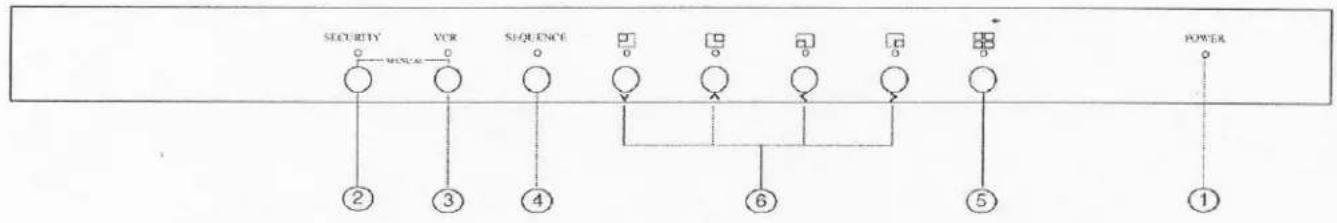
1. Front Panel
MonoQuad-4(B/W) & ChromaQuad-4(Color)
flowchart
graph TD
    A["SECURITY"] --> B["②"]
    C["VCR"] --> D["③"]
    E["SEQUENCE"] --> F["④"]
    G["Power"] --> H["①"]
    style A fill:#fff,stroke:#000
    style C fill:#fff,stroke:#000
    style E fill:#fff,stroke:#000
    style G fill:#fff,stroke:#000
    style B fill:#fff,stroke:#000
    style D fill:#fff,stroke:#000
    style F fill:#fff,stroke:#000
    style H fill:#fff,stroke:#000
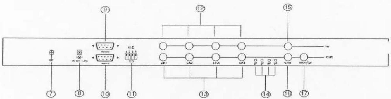
2. Rear Panel
MonoQuad-4(B/W)
- POWER LED: Power status LED.
- SECURITY: Security lock out button. Push this button and hold for 2 seconds to enable security lock operation. Push this button and hold for 2 seconds again to disable the operation.
- VCR: Push this button to enter into VCR operation. In this operation the monitor out will pass through the video signal directly from the video out of the connected VCR. Under VCR operation, Sequence, Quad switch, and channel select buttons (#4\~#6) are all disabled.
Setup: Both SECURITY (#2) and VCR (#3) buttons are also used as menu Setup buttons: Push these two buttons simultaneously to get into menu Setup mode and display page 1 of the setup menu on screen. Please refer to Sec. IV-1 for more details. - SEQUENCE: Push this button to enable full screen auto sequencing mode. Push this button again to disable it.
- QUAD display button: Push this button to switch between Quad and Full Screen display modes.
- Channel Select buttons: When operated in Quad mode with Freeze function ON, these buttons are used to freeze any specific camera by pushing the corresponding channel button. When operated in Full Screen display mode, these buttons are used to call up specific camera to display in full screen mode. If the Freeze function is set to OFF, these buttons are only used as full screen call up buttons.
| Freeze | Quad button (#5) | Ch Select buttons (#6) | Operation |
| ON | ON | ON | Freeze specific camera video in Quad screen mode |
| ON | OFF | ON | Call up specific camera video in full screen mode |
| OFF | ON/OFF | ON | Call up specific camera video in full screen mode |
These buttons are also used as cursor control and character select buttons under menu Setup mode.
- Chassis GND: This contact is provided to ground the chassis to the Earth ground to prevent interference and electrical shock.
- DC 12V: Power input connector. Use 12VDC only.
- Remote control/RS-232 connector: This 9 pin D-sub connector is used to provide remote control operation via a remote keypad or computer. Please refer to Section IV-3 for more details.
- ALARM IN: This female type 9 pin D-sub connector is used for alarm sensor inputs and alarm relay output control connections. It provides Normal Open (NO) and
Normal Close (NC) contacts for alarm out control relay. The alarm sensor contacts can be set to either normal open or normal close type of contact closure through the setup menu. Please refer to Sec. IV.2.1 for more details.
| Pin Assignment for Alarm Connector (female type) | |||||
| Pin # | Pin # | Pin # | |||
| 1 | Sensor 1 | 4 | Sensor 4 | 7 | Relay NO Contact |
| 2 | Sensor 2 | 5 | Reset In | 8 | Common Contact |
| 3 | Sensor 3 | 6 | GND | 9 | Relay NC Contact |
-
Terminations: These impedance switches are used to provide proper termination for each camera input. These switches toggle between 75Ω and Hi-Z impedance. Incorrect termination will degrade the quality of the video signal. All video inputs not “looped through” to another device, the corresponding switches need to be set to 75Ω termination position. If another device is connected to video out loop through connector set the corresponding termination switch to Hi-Z position. Any device connected to the video out loop through connectors needs to be configure to 75Ω video termination. The factory default termination setting is 75Ω.
-
Ch1 In, Ch2 In, Ch3 In, and Ch4 In: Video in connectors: These BNC connectors are used to connect to the video out from camera. Total four cameras can be connected to form a quad screen in the following mapping position. It is very important that each camera be correctly terminated. Please refer to Termination (#11) for proper impedance setting for each video in connector.
| 1 | 2 |
| 3 | 4 |
-
Ch1 Out, Ch2 Out, Ch3 Out, and Ch4 Out: Video out loop through connectors: These connectors are used to loop video signals from each camera out to other devices.
-
G1, G2, G3, and G4: (MonoQuad-4 Only) These VRs are gain control for each corresponding camera input. The control range is +/- 2 dB. However, the loop through outputs (#13) are not controlled by these VRs.
-
VCR in: This BNC connector is to be connected to the "video out" from your VCR. A pre-recorded quad screen video can be played back from the VCR and pass through to be displayed on the Monitor out (#17) from this unit. This connector also allows user to display and program the on screen menu of the connected VCR without reconnecting the cables.
-
VCR out: This BNC connector is to be connected to the "video in" from your VCR. It will only provide a quad screen video to ensure an un-interrupted video recording for all four cameras. The display video is not affected by the control panel and alarm status of the unit.
-
Monitor out: This BNC connector is to be connected to the "video in" of your monitor. It displays live video from camera inputs under live mode and playback video from VCR under VCR mode. The live video displayed here can be in quad screen, full screen, and auto sequencing mode depending on the operation.
-
S-video in: This S-Type connector is to be connected to the "S-video out" from your S-VHS Video recorder.
-
S-video out: This S-Type connector is to be connected to the "S-video in" from your S-VHS Video recorder.
Note: The ChromaQuad-4 will only process signal from "S-video in" (#18), when it receives signals from both "S-video in" (#18) and "VCR in" (#15).
III. How To Install
It is essential that your system be properly hooked up for proper results. Follow the following diagram to install your system.
Please power-off the unit before installation.
1. Basic System Connection with Alarm Input and Output

flowchart
graph TD
    A["AC Adapter"] --> B["Monitor"]
    B --> C["S-VHS VCR"]
    C --> D["VCR"]
    D --> E["Quad display Monitoring"]
    E --> F["Monitor"]
    F --> G["Processor"]
    H["Video In"] --> B
    I["Video Out"] --> B
    J["Power In"] --> K["Alarm Reset"]
    L["sen 1"] --> M["Group 1"]
    N["sen 2"] --> O["Group 2"]
    P["sen 3"] --> Q["Group 3"]
    R["sen 4"] --> S["Group 4"]
    T["Camera 1"] --> U["DC 12V in"]
    V["Camera 2"] --> W["DC 12V in"]
    X["Camera 3"] --> Y["DC 12V in"]
    Z["Camera 4"] --> AA["DC 12V in"]
    AB["NO: Normal Open"] --> AC["Group 1"]
    AD["NC: Normal Close"] --> AE["Group 1"]
2. Remote Control Connection
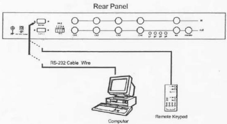
flowchart
graph TD
    A["Computer"] --> B["RS-232 Cable Wire"]
    B --> C["Remote Keypad"]
    C --> D["Out"]
    style A fill:#f9f,stroke:#333
    style B fill:#ccf,stroke:#333
    style C fill:#cfc,stroke:#333
    style D fill:#fcc,stroke:#333
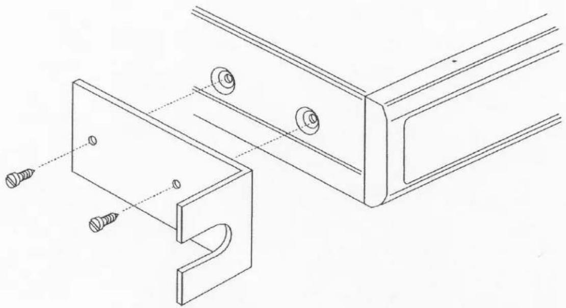
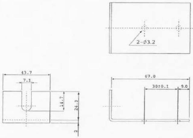
3. Use of Rack-Mounting Kit, QRK-020001:
Rack-Mounting Kit Assembly
natural_image
Technical line drawing of a mechanical assembly with screws and a curved bracket (no text or symbols)Dimension:
Thickness of the material: 1.6 mm
* Rack-mounting kits are sold separately with two pieces per package.
IV. How To Operate:
1. The Setup Menu:
There are two pages in the Setup Menu for MonoQuad-4, and three pages for ChromaQuad-4. Page 1 is used to program TIME, DATE, camera TITLE, and other display settings. Page 2 is used to program Alarm Operations. Page 3 of ChromaQuad-4 is used for display control setting.
Under this mode, channel selection buttons (#6) on the front panel are used for cursor control and text selection. Use the cursor control buttons "<" and ">" to move the cursor to the entry in the menu desired to program, and use the text select buttons "\~" and "\~" to choose the right alphanumeric character to program.
1.1 Page 1 of the Setup Menu - Display Setting
Push Setup buttons, both SECURITY (#2) and VCR (#3) buttons, simultaneously to enter into menu Setup mode and display Setup Menu on the screen.
Page 1: Setting the TIME, DATE, TITLE, and other on screen display features:
Page 1 of ChromaQuad-4,
| CH | TITLE | DWELL TIME | |
| QUAD | 03 S | ||
| 1 | __CH_1_ | 03 S | |
| 2 | __CH_2_ | 03 S | |
| 3 | __CH_3_ | 03 S | |
| 4 | __CH_4_ | 03 S | |
| VIDEO FREEZE | ON | ||
| VIDEO OUT: | MONITOR | VCR | |
| TITLE: | ON | ON | |
| TIME: 08 : 10 : 10 | ON | ON | |
| DATE: 12 - 25 - 1998 | ON | ON | |
Page 1 of MonoQuad-4
| CH TITLE | DWELL TIME |
| QUAD | 03 S |
| 1 _CH_1_ | 03 S |
| 2 _CH_2_ | 03 S |
| 3 _CH_3_ | 03 S |
| 4 _CH_4_ | 03 S |
| VIDEO FREEZE | ON |
| TITLE: | ON |
| TIME: 08 : 10 : 10 | ON |
| DATE: 12 - 25 - 1998 | ON |
1.1.1 TITLE setup:
The Title entry is used to program camera title for each individual camera input. Eight characters can be entered for MonoQuad-4 and ten characters can be entered for ChromaQuad-4.
1.1.2 DWELL Time setup:
When operated under auto Sequencing mode, these entries are used to set the dwell time of each video source displayed on Monitor out. The menu includes the entries for all video sources and also quad screen display, and their associated dwell time. Dwell time can be programmed by setting a number between 00 to 99 seconds. Set the dwell time to 0 second to exclude the video source from the auto switching sequence; set it from 1 to 99 second to include the video source to the auto switching sequence.
1.1.3 Video Freeze: This entry is used to enable or disable the video freeze operation.
-
If this entry is set to ON, user can freeze the specific camera video under live quad display mode by pressing corresponding channel buttons on the front panel. However, user can only call up specific camera if the unit is operated under full screen display mode.
-
If this entry is set to OFF, there will be no video freeze function. Under this mode, the unit will only call up specific camera in live full screen display by pressing corresponding channel buttons regardless the original display mode of the unit.
1.1.4 TIME/DATE setup:
Time and date information can be superimposed on the video signal from Monitor out (#17), VCR out (#16), and S-video out (#19) connectors.
Note: Time and date information will not be displayed in Full Screen display mode for MonoQuad-4.
The date and time are displayed in "MM-DD-YYYY HH:MM:SS" format for NTSC/EIA system, and "DD-MM-YYYY HH:MM:SS" format for PAL/CCIR system. The date format used here are in conformity with the definition of year 2000 conformity, which means that neither performance nor functionality of the unit is affected by dates prior to, during and after the year 2000.
1.1.5 TITLE/TIME/DATE ON/OFF entries are used to enable or disable its superimpose on corresponding video out signals.
1.2 Page 2 of the setup menu: Alarm Setting
Push SECURITY button (#2) again to display page 2 of the setup menu on the screen (Fig 1.2). This Alarm Setting menu is used to set the desired alarm configuration like sensor type, sensor sensitivity, alarm hold duration, buzzer, and others.
Page 2 for both MonoQuad-4 & ChromaQuad-4
| ALARM SETTING | |||
| CH | SENSOR | TYPE | STATUS |
| 1 | OPEN | NO | ON? |
| 2 | OPEN | NO | ON? |
| 3 | OPEN | NO | ON? |
| 4 | OPEN | NO | ON? |
| SENSITIVITY: | 0.3 S | ||
| DURATION: | 30 S | ||
| BUZZER: | ON | ||
| V-LOSS ALARM: | ON | ||
| V-LOSS RELAY: | ON | ||
Fig 1.2
Page 3 for ChromaQuad-4
| REFRESH | RATE: 30 | ||
| BRIGHT: | 48 | BRIGHT: | 48 |
| CONTRAS: | 44 | CONTRAST: | 44 |
| COLOR: | 45 | COLOR: | 45 |
| HUE: | 40 | HUE: | 40 |
| FILTER: | ON | FILTER: | ON |
| BRIGHT: | 48 | BRIGHT: | 48 |
| CONTRAST: | 44 | CONTRAST: | 44 |
| COLOR: | 45 | COLOR: | 45 |
| HUE: | 40 | HUE: | 40 |
| FILTER: | ON | FILTER: | ON |
Fig 1.3
1.2.1 Sensor Type:
The device will first detect the type of the sensor connected to each alarm sensor input contact for each channel. The detected sensor contact status will be displayed in the first column following each channel number. They can be on either OPEN or CLOSE.
The menu then allows user to enter a desired type of the sensor for each channel in next column. NO means Normally Open. NC means Normally Close.
Then the menu allows user to enable or disable sensor activated alarm for each camera input in the next column. ON will enable sensor alarm detection of the contact. OFF will ignore the sensor input and disable the sensor alarm detection from the contact.
Last column on this part of the menu shows the actual test result of the detected sensor type and the programmed configuration. If the programmed sensor type is different from the actually connected type, a blinking “?” message will be displayed. In this case, the buzzer will be activated when you exit the setup operation to signal user about the difference.
1.2.2 Alarm Sensitivity
Alarm sensitivity can be programmed to different level by setting the period of the triggered pulse detected by the sensor. The available range of settings is from 0.2s to 0.8s.
1.2.3 Alarm Hold Duration
The alarm hold duration can be set from 0 second to 59 minutes. The duration can also be set to non-stop by choosing “>>”. In this mode, the activated alarm can only be reset by connecting the alarm reset contact to ground.
1.2.4 Buzzer
The device has a build-in buzzer to signal a detected alarm through audio. User can choose to disable the buzzer by setting it to OFF.
1.2.5 V-Loss Alarm:
This entry is used to enable or disable the video loss alarm. The device automatically detects loss of video at any input if this entry is set to ON. User can choose to disable this feature by setting it to OFF for applications like video conferencing or others that will need constant video source switching.
1.2.6 V-Loss Relay Control:
The device is equipped with an alarm controlled relay, which can be activated by both sensor triggered alarm and video loss alarm. This entry allows user to disable the relay activation from a loss of video in any camera input.
1.3 Page 3 of the setup menu: Display control for ChromaQuad-4
1.3.1 Refresh rate setting:
This entry is used to choose video refresh rate between 30 (25) and 60 (50) fields per second.
-
Set to 60 (50 for PAL) to achieve a better performance for motion video type of display.
-
Set to 30 (25 for PAL) to achieve a better performance for still picture type of display.
1.3.2 Bright, Contrast, Color, and Hue adjustment:
Use these entries to make picture adjustments to your preference for each individual camera. The adjustment ranges are all from 0 to 99. Hue adjustment is only available for NTSC system.
1.3.3 Filter switch:
The video Filter feature allows you to reduce the excessive flicker problem comes with certain video source. Set this entry to ON to achieve a more stable and better quality video display.
1.4 Save the setting and exit menu Setup mode:
Push the SECURITY button (#2), again to save the setting and exit menu setup mode.
1.5 Factory default settings:
The system setup can be reset to factory default by pushing and hold SECURITY (#2) and VCR (#3) buttons down and power on the unit simultaneously until the quad display shows up on the screen.
2. Alarm Operations: Sensor Activation and Video Loss
2.1 Sensor Activated Alarm:
The device is equipped with 1 alarm sensor contact for each camera input. If any alarm is activated the device will:
- Activates the built-in buzzer and also the alarm output relay.
- Switches the corresponding channel indicator LED to blinking mode
- Displays and overlays ALARM warning message and the title of the camera alternately on the activated camera through Monitor out (#17) video in full screen mode for ChromaQuad-4. In the mean time, same message will be displayed on VCR out video in quad screen mode for three models.
The sensor activated alarm can be cleared by any of the following:
-
Connecting the Alarm Reset In contact, pin #5, of the female 9 pin D-sub connector (#10) to GND.
-
The Alarm Duration time elapses.
2.2 Video Loss Alarm:
Video loss alarm feature can be enabled or disabled in the on screen menu to setup the device for applications like video conference, which require a constant video source switching. Please refer to Sec. 1.2.5 for more detail.
2.2.1 When video loss alarm feature is enabled and any loss of video is detected, this device will:
-
Activates the built-in buzzer and also the alarm out relay if the V-Loss Relay Control is set to ON.
-
Switches the corresponding channel LED to blinking mode.
-
Freezes the last picture before the loss of the video for alarm documentation.
-
Displays "Video Loss" message and the corresponding camera "Title" alternately on the screen.
2.2.2 If the video loss alarm feature is disabled, the device will simply display blank screen without any message and any other acknowledgement action if any loss of video is detected. This is too allows applications that require video source switching without any warning signal.
2.3 The warning message and the buzzer can be cleared by pushing SECURITY button (#2) for more than 2 seconds if the device is operated under Security lock ON mode, or push any button on the front panel if the device is operated under Security lock OFF mode.
3. Remote Control Operations
The device may be controlled via the male type 9 pin D-sub/RS-232 connector (#9) from a remote keypad, terminal, or computer using ASCII code.
Note: Please power off the unit before connecting the Remote Control keypad.
3.1 Pin assignment of the male type 9 pin D-sub connector:
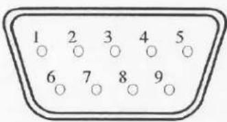
(Male Type)
| Pin Assignment for Remote Control Connector | |||||
| 1 | GND | 4 | NC | 7 | VCC |
| 2 | RX | 5 | NC | 8 | GND |
| 3 | TX | 6 | VCC | 9 | GND |
When a remote keypad is used to control the device, pin 1, 2, and 3 are used for control signal transmission; pin 6, 7, 8, and 9 are used for providing power to the remote keypad.
Note: If a terminal or computer is used to control this device through a RS-232 port, pin 6, 7, 8, and 9 must be disconnected to prevent connecting the Vcc and GND signals from the device to the terminal or computer. A RS-232 port only uses pin 1, 2, and 3 for control signal transmission.
3.2 If a remote keypad is connected to the 9 pin D-sub connector, all the control functions provided in the front panel will be also available from the keypad.
3.3 A terminal or computer can be connected to the male type 9 pin D-sub connector on the real panel from its RS-232 port to control this device using standard, uppercase ASCII codes.
3.3.1 The ASCII command codes for the device are listed in the table below. The transmission protocol is 1200 baud rate, 8 data bit, 1 start bit, 1 stop bit, and no parity.
| Function | ASCII Command Code |
| Model Number | MonoQuad-4, ChromaQuad-4 |
| Quad Screen Display | E |
| CH 1 | A |
| CH 2 | B |
| CH 3 | C |
| CH 4 | D |
| Freeze *1 | EA, EB, EC, ED |
| Auto Switching Sequence | F |
| VCR/Live | G |
| Key Lock | H |
| Setup Menu *2 | GH |
| Text Select Down *3 | (GH) A |
| Text Select Up | (GH) B |
| Cursor Left | (GH) C |
| Cursor Right | (GH) D |
| Alarm Reset | I |
a. In order to control the device to operated in freeze mode, the computer has to first send command code "E" or "G" to put the unit in Quad display and then followed by the corresponding channel code for each specific channel. Input the corresponding channel code again to clear the freeze mode.
Example: EA, EB, EC, and ED for freezing the video in channel 1 to 4. Input "A", "B", "C", and "D" again to clear the freeze mode for each channel.
b. Setup menu is switched ON by sending VCR and SECURITY button (#2 and #3) codes together.
c. Text Select and Cursor Control operations can be performed only under menu Setup mode.
Note: Please contact ELMO Manufacturing Corporation's Technical Department for the most updated command codes and code library before programming.
3.3.2 Status Codes:
Right after any remote control device has sent out above mentioned control command codes to the unit, or there is any status change on the unit, the device
will respond with a 2-byte status code back through RS-232 port to assist user to do remote programming to better control the unit.
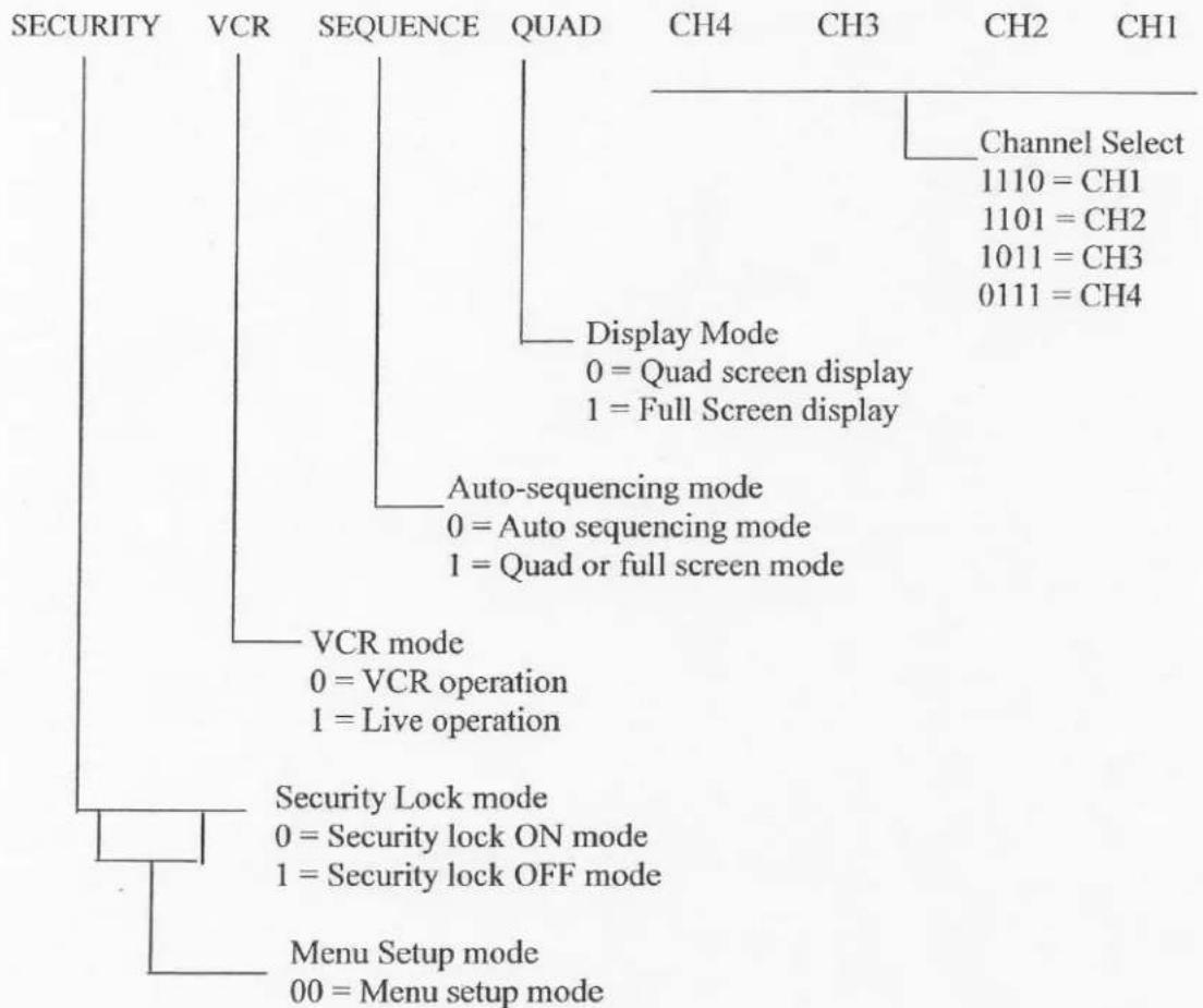
3.3.2 The configuration of the status code:
There are total 2 bytes of the status codes. Byte one, the first 8 bits, shows the current status of the operation modes that the unit is in. Byte two, the second 8 bits, shows the current status of the alarm operations of the unit.

BYTE 1: Status code for normal operation modes

flowchart
graph TD
    A["SECURITY"] --> B["VCR"]
    B --> C["SEQUENCE"]
    C --> D["QUAD"]
    D --> E["CH4"]
    D --> F["CH3"]
    D --> G["CH2"]
    D --> H["CH1"]
    I["Channel Select 1110 = CH1\n1101 = CH2\n1011 = CH3\n0111 = CH4"] --> J["Display Mode\n0 = Quad screen display\n1 = Full Screen display"]
    K["Auto-sequencing mode\n0 = Auto sequencing mode\n1 = Quad or full screen mode"] --> L["VCR mode\n0 = VCR operation\n1 = Live operation"]
    M["Security Lock mode\n0 = Security lock ON mode\n1 = Security lock OFF mode"] --> N["Menu Setup mode\n00 = Menu setup mode"]
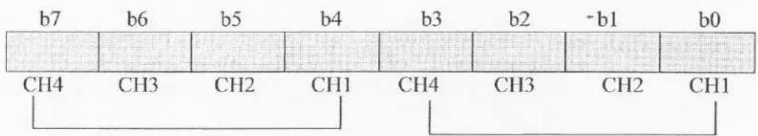
BYTE2: Status code for alarm operations:
The first 4 bits show the sensor activated alarm status of each channel; next 4 bits show the video loss alarm status of each channel. The digit “1” means alarm event is detected, and “0” means no alarm event is detected.
b7 - b4: Sensor Activated Alarm
b3 - b0: Video Loss Alarm
Sensor activated Alarm
Video Loss Alarm
$$ 0 0 0 1 = \mathrm{CH} 1 \text { a c t i v a t e d } $$
$$ 0 0 1 0 = \mathrm{CH} 2 \text { a c t i v a t e d } $$
$$ 0 1 0 0 = \mathrm{CH} 3 \text { a c t i v a t e d } $$
$$ 1 0 0 0 = \mathrm{CH} 4 \text { a c t i v a t e d } $$
$$ 0 0 0 1 = \mathrm{CH} 1 \text { a c t i v a t e d } $$
$$ 0 0 1 0 = \mathrm{CH} 2 \text { a c t i v a t e d } $$
$$ 0 1 0 0 = \mathrm{CH} 3 \text { a c t i v a t e d } $$
$$ 1 0 0 0 = \mathrm{CH} 4 \text { a c t i v a t e d } $$