
EV-400AF - Projector Elmo - Free user manual and instructions
Find the device manual for free EV-400AF Elmo in PDF.


| Product Type | Document Camera / Visual Presenter |
| Model | EV-400AF |
| Brand | Elmo |
| Image Sensor | 1/3-inch CMOS |
| Total Pixels | Approx. 5.0 Megapixels |
| Optical Zoom | 12x (approx.) |
| Digital Zoom | Up to 4x |
| Maximum Resolution | 1920 x 1080 (Full HD) |
| Frame Rate | 30 fps (full HD) |
| Output Interfaces | HDMI, USB, VGA (optional) |
| Light Source | LED (built-in) |
| Power Supply | AC 100-240V, 50/60Hz |
| Power Consumption | Approx. 20W |
| Dimensions (W x H x D) | Approx. 350mm x 120mm x 350mm (folded) |
| Weight | Approx. 2.5 kg |
| Main Functions | Live image capture, annotation, freeze, split-screen, recording |
| Maintenance | Clean lens with soft cloth; avoid liquids |
| Safety | Do not expose to moisture; use only supplied adapter |
| Spare Parts & Reparability | Contact Elmo service for replacement bulbs and parts |
| General Information | Designed for classroom and business presentations |
Frequently Asked Questions - EV-400AF Elmo
User questions about EV-400AF Elmo
0 question about this device. Answer the ones you know or ask your own.
Ask a new question about this device
Download the instructions for your Projector in PDF format for free! Find your manual EV-400AF - Elmo and take your electronic device back in hand. On this page are published all the documents necessary for the use of your device. EV-400AF by Elmo.
USER MANUAL EV-400AF Elmo
natural_image
Line drawing of a desktop computer with adjustable arm and screen (no text or symbols)IMPORTANT SAFEGUARDS
- Read Instructions – All the safety and operating instructions should be read before the appliance is operated.
■ Retain Instructions – The safety and operating instructions should be retained for future reference.
■ Heed Warnings – All warnings on the appliance and in the operating instructions should be adhered to.
■ Follow Instructions – All operating and use instructions should be followed.
- Cleaning – Unplug this product from the wall outlet before cleaning. Do not use liquid cleaners or aerosol cleaners. Use a damp cloth for cleaning.
- Attachments – Do not use attachments not recommended by the product manufacturer as they may cause hazards.
■ Water and Moisture – Do not use this product near water – for example, near a bath tub, wash bowl, kitchen sink, or laundry tub, in a wet basement, or near a swimming pool, and the like.
■ Accessories – Do not place this product on an unstable cart, stand, tripod, bracket, or table. The product may fall, causing serious injury to a child or adult, and serious damage to the product. Use only with a cart, stand, tripod, bracket, or table recommended by the manufacture, or sold with the product. Any mounting of the product should follow the manufacture's instructions, and should use a mounting accessory recommended by the manufacturer.
■ Ventilation – Slots and openings in the cabinet are provided for ventilation and to ensure reliable operation of the product and to protect it from overheating, and these openings must not be blocked or covered. The openings should never be blocked by placing the product on a bed, sofa, rug, or other similar surface. This product should never be placed near or over a radiator or heat register. This product should not be placed in a built-in installation such as a bookcase or rack unless proper ventilation is provided or the manufacture's instructions have been adhered to.
■ Power Sources – This product should be operated only from the type of power source indicated on the marking label. If you are not sure of the type of power supply to your home, consult your appliance dealer or local power company. For products intended to operate from battery power, or other sources, refer to the operating instructions.
- Grounding or Polarization – This product may be equipped with either a polarized 2-wire AC line plug (a plug having one blade wider than the other) or a 3-wire grounding type plug, a plug having a third (grounding) pin. The 2-wire polarized plug will fit into the power outlet only one way. This is a safety feature. If you are unable to insert the plug fully into the outlet, try reversing the plug. If the plug still fails to fit, contact your electrician to replace your obsolete outlet. Do not defeat the safety purpose of the polarized plug. The 3-wire grounding type plug will fit into a grounding type power outlet. This is a safety feature. If you are unable to insert the plug into the outlet, contact your electrician to replace your obsolete outlet. Do not defeat the safety purpose of the grounding type plug.
■ Power-Cord Protection – Power-supply cords should be routed so that they are not likely to be walked on or pinched by items placed upon or against them, paying particular attention to cords at plugs, convenience receptacles, and the point where they exit from the product.
■ Lightning – For added protection for this product during a lightning storm, or when it is left unattended and unused for long periods of time, unplug it from the wall outlet and disconnect the antenna or cable system. This will prevent damage to the product due to lightning and power-line surges.
■ Overloading – Do not overload wall outlets, extension cords, or integral convenience receptacles as this can result in a risk of fire or electric shock.
■ A product and cart combination should be moved with care.
Quick stops, excessive force, and uneven surfaces may cause the product and cart combination to overturn.

■ Object and Liquid Entry – Never push objects of any kind into this product through openings as they may touch dangerous voltage points or short-out parts that could result in a fire or electric shock. Never spill liquid of any kind on the product.
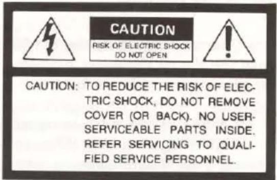
- Servicing – Do not attempt to service this product yourself as opening or removing covers may expose you to dangerous voltage or other hazards. Refer all servicing to qualified service personnel.
■ Damage Requiring Service – Unplug this product from the wall outlet and refer servicing to qualified service personnel under the following conditions:
- When the power-supply cord or plug is damaged.
- If liquid has been spilled, or objects have fallen into the product.
• If the product has been exposed to rain or water.
- If the product does not operate normally by following the operating instructions. Adjust only those controls that are covered by the operating instructions as an improper adjustment of other controls may result in damage and will often require extensive work by a qualified technician to restore the product to its normal operation.
- If the product has been dropped or damaged in any way.
- When the product exhibits a distinct change in performance – this indicates a need for service.
- Replacement Parts – When replacement parts are required, be sure the service technician has used replacement parts specified by the manufacturer or have the same characteristics as the original part. Unauthorized substitutions may result in fire, electric shock or other hazards.
■ Safety Check – Upon completion of any service or repairs to this product, ask the service technician to perform safety checks to determine that the product is in proper operating condition.
- Heat – The product should be situated away from heat sources such as radiators, heat registers, stoves, or other products (including amplifiers) that produce heat.

SA 1965
The lightning flash with arrowhead symbol, within an equilateral triangle, is intended to alert the user to the presence of uninsulated "dangerous voltage" within the product's enclosure that may be of sufficient magnitude to constitute a risk of electric shock to persons.

SA 1966
The exclamation point within an equilateral triangle is intended to alert the user to the presence of important operating and maintenance (servicing) instructions in the literature accompanying the appliance.
WARNING:
TO REDUCE THE RISK OF FIRE OR ELECTRIC SHOCK, DO NOT EXPOSE THIS PRODUCT TO RAIN OR MOISTURE.
INFORMATION
This equipment has been tested and found to comply with the limits for a Class A digital device, pursuant to Part 15 of the FCC Rules. These limits are designed to provide reasonable protection against harmful interference when the equipment is operated in a commercial environment. This equipment generates, uses, and can radiate radio frequency energy and, if not installed and used in accordance with the instruction manual, may cause harmful interference to radio communications. Operation of this equipment in a residential area is likely to cause harmful interference in which case the user will be required to correct the interference at his own expense.
USER-INSTALLER CAUTION: Your authority to operate this FCC verified equipment could be voided if you make changes or modifications not expressly approved by the party responsible for compliance to Part 15 of the FCC rules.
INTRODUCTION
Thank you for purchasing the ELMO Visual Presenter EV-400AF.
To use the Visual Presenter properly, carefully read this operation manual before use.
After reading the manual, keep it in a convenient place for quick reference.
The EV-400AF is the easy-to-operate and portable video presentation unit, equipped with a high-resolution CCD (Charge Coupled Device) camera.
Featuring a 8X magnification zoom lens and a high accuracy auto focusing system, the EV-400AF captures all types of presentation materials, ex: 3-D objects, transparencies, to show or record through monitor TV, VCR, etc.
BEFORE YOUR USE
Follow the instructions in this section to ensure safe operation. (Failure to follow these instructions may result in incorrect operation or malfunction of the Presenter.)
*Apply to the specified AC power source.
* Disassembling or modifying the Visual Presenter may results in electrical shock and machine malfunction.
We are not responsible for any deterioration or failure of the Visual Presenter caused by disassembling or modifying by the user.
* Connecting or disconnecting the power cord should be carried out while firmly holding the plug.
*If the Presenter is left unused for a long period, disconnect the power cord for safety. Do not expose the Presenter to direct sunlight, high temperature, high humidity, or dust.
* Avoid storing or using the Presenter where vibration occurs.
*Install the Presenter in the following conditions.
Temperature : 5°C\~40°C (41°F\~104°F)
Humidity : 30%\~85% (Avoid humid places, since himidity inside the products may cause failure of the set.)
* If the Presenter is used for purposes other than specified, we cannot guarantee its performance, service life or safety.
* Do not place or drop heavy objects or containers of liquid on the stage.
* Use only a soft, dry cloth for cleaning. Using benzine or thinner for cleaning may damage the coating or resin.
* Do not directly point the camera lens into the sun or similar since the camera will be damaged.
* The socket-outlet shall be installed near the equipment and shall be easily accessible.
CONTENTS
Part names and functions 5
Setting up 9
Connection to monitor TV 10
*Connection to composite video-in terminal
*Connection to S video-in terminal
Operating procedures 11
*Simple steps for presenting printed materials
*Simple steps for viewing transparencies as slide film
*For use as a conventional video camera
Stowing 12
Various functions 13
*Lighting
*Input selection
*Nega/posi conversion
*Color/B&W selection
*Zoom
* Focus
* White balance
*Electronic shutter speed
* Iris
* Microphone
* LCD monitor shoe
External sync. adjustment 19
Manual remote 20
RS-232C specifications 21
* Set up
* Cable connection
*RS-232C connector specification (DSUB-9P)
*Transmission mode
*RS-232C terminal and DIP-SW position
* List of transmission commands
* Data format specifications
Trouble shooting hints 25
Specifications 26
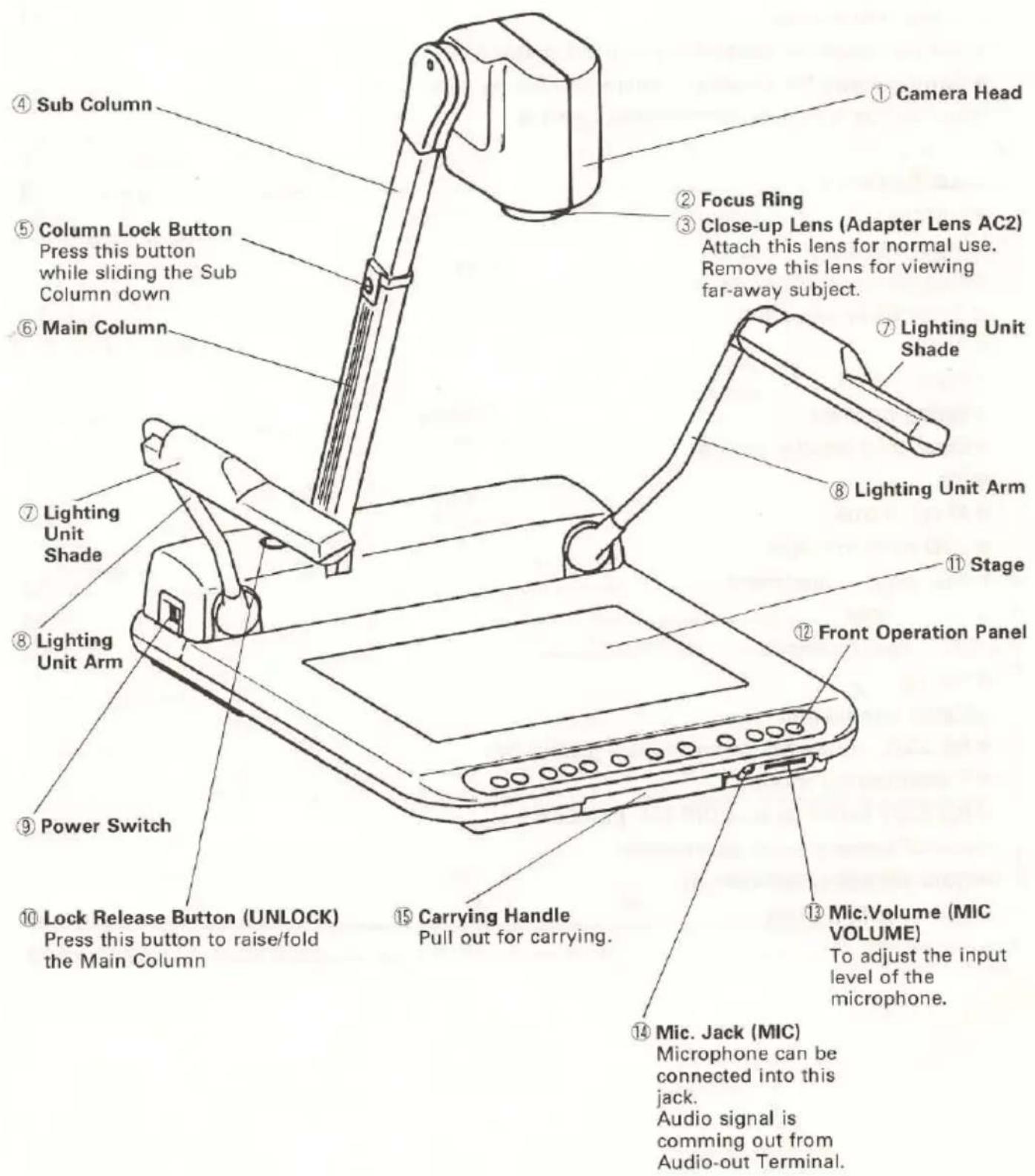
PART NAMES AND FUNCTIONS

flowchart
graph TD
    A["⑯ Lighting Buttons"] --> B["LAMP"]
    A --> C["INPUT"]
    A --> D["Nega/Posi Conversion Button"]
    A --> E["ZOOM"]
    A --> F["Auto Focus Button"]

    B --> G["UPPER ON/OFF BASE"]
    C --> H["INTERNAL ON/OFF"]
    D --> I["POSLE P"]
    D --> J["NEGA N"]
    D --> K["COLOR/B&W C"]
    E --> L["ZOOM TLE"]
    E --> M["WDCE"]
    F --> N["FOCUS MANU"]

    style A fill:#f9f,stroke:#333
    style B fill:#ccf,stroke:#333
    style C fill:#ccf,stroke:#333
    style D fill:#ccf,stroke:#333
    style E fill:#ccf,stroke:#333
    style F fill:#ccf,stroke:#333
    style G fill:#cfc,stroke:#333
    style H fill:#cfc,stroke:#333
    style I fill:#cfc,stroke:#333
    style J fill:#cfc,stroke:#333
    style K fill:#cfc,stroke:#333
    style L fill:#cfc,stroke:#333
    style M fill:#cfc,stroke:#333
| Part Name | Function | Reference Page | |
| 16 | Lighting Buttons | To turn on/off the light. | 13 |
| 17 | Input Selection Button | To change input line. | 13 |
| 18 | Nega/Posi Conversion Button | For viewing negative films. | 14 |
| 19 | Color/B&W Button | For viewing black and white material, such as documents. | 14 |
| 20 | Zoom Buttons | To adjust the image size. | 14 |
| 21 | Focus Buttons | To adjust focus (Powered). | 15 |
| 22 | Auto Focus Button | One-step auto focus for automatic focusing. | 15 |
○Rear Panel

| Part Name | Function | Reference Page | |
| 23 | Video-in Terminal 2 S-Video/C-Video | Video signal is output from the video-out terminal 27 when input selection is set at AV2. | 10 |
| 24 | Audio-in Terminal 2 | Audio signal is output from the audio-out terminal 28 when input selection is set at AV2. | |
| 25 | Video-in Terminal 1 S-Video/C-Video | Video signal is output from the video-out terminal 27 when input selection is set at AV1. | 10 |
| 26 | Audio-in Terminal 1 | Audio signal is output from the audio-out terminal 28 when input selection is set at AV1. | |
| 27 | Video-out Terminal S-Video/C-Video | Connected to monitor TV, etc. | 10 |
| 28 | Audio-out Terminal | Audio-out terminal, Mic. (monaural), AV1, AV2 connected to monitor TV. | |
| 29 | Ext. Sync. Input Ter-minal | GEN-LOCK terminal for external synchronization. | 19 |
| 30 | RS-232C Terminal | Controlled by general purpose personal computer. | |
| 31 | Remote Terminal | Input terminal for external control signal. | 20 |
| 32 | Power Cord Recepta-cle | Connected to power cord connector. | |
| 33 | |||
| 34 | AC Outlet | Max 400W | |
| 35 | LCD Monitor TV Shoe Socket | For attaching optional LCD monitor shoe MS-100 | 18 |

| Part Name | Function | Reference Page | |
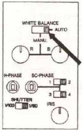
| 36 | White Balance Switch | Select the mode for white balance adjustment. Set at [AUTO] for normal use. | 16 |
| 37 | Color Balance Adjusting Knobs | To adjust white balance for manual adjustment. | 16 |
| 38 | H-phase Control Volume | To adjust the horizontal sync. phase. | 19 |
| 39 | Color Phase Control Volume/Switch | To adjust the sub carrier phase. | 19 |
| 40 | Shutter Speed Selection Switch | To select 1/60 sec. or 1/100 sec. electronic shutter speed. | 17 |
| 41 | Iris Control Knob | To adjust the brightness of image. Set at middle position for normal setting. | 17 |
SETTING UP
- Press the lock release button [UNLOCK] and raise the column. Raise the column until the lock release button gets back to the original position.

- Extend the sub column until it is locked.
- Adjust the camera head to the required position.

natural_image
Simple line drawing of a mechanical device with an upward arrow and rotation arrow (no text or symbols)- Set up the lighting units to stop positions.
- Connect the power cord to the AC outlet.

natural_image
Line drawing of a mechanical device with a lever and rotating arm (no text or symbols)CONNECTION TO MONITOR TV
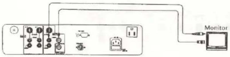
Connect the supplied video cable to the video-out terminal of the Visual Presenter and to the video-in terminal of the monitor TV.
■ Be sure to turn the power off before making connections (in order to protect the Visual Presenter and the other connected machines).
■ Hold the cable plug firmly when disconnecting the video cable.
○Connection to composite video-in terminal
Connection example for the device with the composite video-in terminal.
Connect with the supplied video/audio cable with RCA pin plugs or a commercially-available BNC cable.
(The Visual Presenter has one each of BNC and RCA jacks, and either jack is selectable.)
○Connection to S video-in terminal
Connection example for the device with the S video-in terminal.
S video-out terminal (mini DIN 4P) of the Visual Presenter is connected to the S video-in terminal of the TV monitor / video.
For S video mode, use a commercially-available S video connection cable.
If the device to be used is provided with a Y/C separate connector, a conversion adapter is necessary.

OPERATING PROCEDURES
○Simple steps for presenting printed materials
- Turn the power switch of the Visual presenter ON. (Connection to the monitor should be previously executed.)
* Various functions of the Visual Presenter are initialized. The initial settings of those functions are displayed by their respective indicators.
- Place the object on the stage.
While observing the image on the TV monitor, adjust the zoom button to obtain the optimum size.
- Press the auto focus button for focusing.
* The covered area of the auto focus function is up to approx. 10 cm above the stage surface.

natural_image
Line drawing of a desktop computer with adjustable arm and control panel (no text or symbols)
○Simple steps for viewing transparencies as slide film
- Press the lighting button [BASE].
The [BASE] indicator lights on, and then the built-in baselight is turned ON.
-
Press the nega/posi conversion button, and the indicator shows [N] (Negative) mode.
-
When turning off the baselight, press the lighting button [BASE] again.

○For use as a conventional video camera
-
Remove the close-up lens when shooting the object at telephoto position.
-
Turn the camera head to horizontal position.
This allows you to capture pictures on the wall, etc.

natural_image
Line drawing of a mechanical device with a dial and lever (no text or symbols)STOWING
- Turn the power switch OFF before disconnecting the power cord and the video cable.
Note: Be sure to hold the plug firmly when disconnecting. Do not pull the cord out carelessly.
- Fold down the lighting unit arms.
Note: The arm, which is first folded down, should be turned and then the other as per the illustration so that two arms are closely located to the stage.
- Turn the camera head to the illustrated position.
Note: Stow the camera head as per the illustration, or the stage surface or the lens may be damaged.
-
Press the column lock button, and shorten the sub column fully.
-
Press the lock release button [UNLOCK], and fold down the main column.
Note: The illustration shows the fixed folded-down position for the column.
Do not further press the column with excessive strength.

natural_image
Mechanical device with lever mechanism and curved arrows indicating motion (no text or symbols)
natural_image
Line drawing of a mechanical device with a lever and rotating arm (no text or symbols)

VARIOUS FUNCTIONS
○Lighting
Lighting unit for viewing materials such as printed matter, 3-D object, and Baselight for viewing slide and negative film (transparencies) are built-in.
With the lighting button pressed, the indicator flashes, and after a few seconds, the fluorescent lamps light on.
To turn the lamps off, press the lighting button again.
Select the [UPPER] or [BASE] mode.
(It is not possible to simultaneously use both the upper lighting unit and the base-light.)
It is advisable to use the upper lighting unit to obtain the clear image with better color rendering especially when the stage is not sufficiently illuminated by room lights or 3-D object is to be viewed.

○Input selection
Images from two separate AV sources, such as a VCR and video camera, are selected to be projected on the monitor by pressing the input selection button.

List of Video-In/Out Terminal Selections
| Input\Output | Video-out terminal | Audio-out terminal | ||||
| S-VIDEO | C-VIDEO | |||||
| RCA | BNC | |||||
| INTERNAL | Built-in camera | S-VIDEO | ○ | - | - | - |
| C-VIDEO | - | ○ | ○ | - | ||
| Mic. | - | - | - | ○ | ||
| AV 1 | Ext. video signal | S-VIDEO | ○ | - | - | - |
| C-VIDEO | - | ○ | ○ | - | ||
| Ext. audio signal | - | - | - | ○ | ||
| AV 2 | Ext. video signal | S-VIDEO | ○ | - | - | - |
| C-VIDEO | - | ○ | ○ | - | ||
| Ext. audio signal | - | - | - | ○ | ||
○Nega/posi conversion
This function is used to view negative film as positive images.
Press the nega/posi conversion button, and the indicator shows [N] (negative).
Press the button again changes to normal [P] (positive) mode.

○Color/B&W selection
It is advisable to use this mode for viewing the B&W materials as documents, and clear image with no color blur is obtained.
For normal use, set to [C] (color) mode.
Pressing the color/B&W button changes to [B&W] or [C] mode in succession.

○Zoom
When the zoom button is pressed to select [TELE], the image gets larger. When the zoom button is pressed to select [WIDE], the image gets smaller.

○Focus
(1) Auto Focus
- When the auto focus button is pressed, the indication lamp is turned ON and OFF during focusing.
● The Visual Presenter features a one-step auto focus function. Once focusing is completed, the auto focus function is released. Even if the object is moved, the focus remains unchanged.

● To focus the image with auto focus setting, set the zoom button at extreme telephoto position so that more accurate image can be obtained.
- It is difficult to automatically focus on an object under the following conditions. Select the focus mode to manual focus on objects in these conditions.
* Object bearing little contrast.
* Object with a fine repeated pattern such as lateral stripes, or a checkered pattern.
* Bright object or one with reflecting strong light.
* The background of the object is bright, or the contrast is too clear.
* Picture plane itself is dark.
* The positions of the objects are far and near.
* Moving object.
- When using the manual focus during auto focusing, the auto focus function is cancelled.
(2) Powered Manual Focus
Press the focus button [N] or [F] for manual focusing.
This function is used to view 3-D object of which any part can be focused.
Note: The coverage area of manual focusing is up to approx. 10cm above from the stage surface.

○White balance
(1) Full-Auto mode:
With the white balance switch at [AUTO] position, the camera automatically adjusts to the color temperature and adjusts the white balance. The camera will then automatically follow the change in color temperature of the object.
Set [AUTO] position for normal use.
(2) Manual mode
With the white balance switch at [MANU.] position, turn the R (red) and B (blue) knobs while observing the white object on the monitor screen.

flowchart
graph TD
    A["WHITE BALANCE AUTO"] --> B["MANU."]
    B --> C["R"]
    B --> D["B"]
    E["H-PHASE"] --> F["1"]
    F --> G["2"]
    G --> H["3"]
    H --> I["4"]
    J["SC-PHASE"] --> K["SHUTTER 1/100"]
    K --> L["1/80"]
    M["IRIS"] --> N["Ground"]
Electronic shutter speed
Under the 50Hz electrical condition area, the flickering may appear under the fluorescent lamps, etc. with the EV-400AF set at "1/60" mode.
In this case, select "1/100" sec. shutter speed.
Leave the 1/60 sec. mode (original setting) for the use under the 60Hz area.

○Iris
Exposure is automatically compensated when the iris control knob is kept at middle position.
Exposure can be manually adjusted by turning the iris control knob.

○Microphone
When using the video monitor with the audio-in terminal, connecting the microphone into the mic. jack allows the simultaneous output of the audio signal from the monitor speaker and video signals.
Adjust the mic. volume to obtain the optimum volume of the microphone.
The audio signal of the microphone is output from the audio out terminal regardless of position of the input selector.

○LCD monitor shoe
The optional LCD monitor shoe, type MS-100 is available for attaching an LCD monitor (commercially-available) with a tripod screw hole onto the EV-400AF.
(Refer to the operation manual for the LCD monitor for connection.)

EXTERNAL SYNC. ADJUSTMENT
This adjustment is necessary when images from several AV sources, such as the Visual Presenter, video cameras, and other equipment (including ELMO film-to-video converter TRV-35H, TRV-16G), are composed to be projected on a single monitor.
Horizontal sync. position adjustment and sub carrier position adjustment are required to match the color phases of each image.
A video mixer is necessary to reproduce a composite image. The connection method differs depending on the type of the video mixer. Refer to the instruction manual of the respective video mixer for additional information on connection method.
● Horizontal sync. phase adjustment
This adjustment is used to adjust the horizontal phase when the Visual Presenter is subject to ext. sync. (GEN-LOCK). When adjusting the phase, use an adequate (−) screwdriver or the like.

● Sub-Carrier Phase Adjustment
This adjustment is carried out if the color phase of the image output signal of the Visual Presenter is not appropriately adjusted to the base signal when overlapping images.
Set the color phase control switch for adjusting the color phase of the image to color phase of the base signal to bring each color phase as close as possible.
Fine adjusting by color phase volume is further carried out.
When adjusting the sub-carrier phase, use an adequate (−) screwdriver or the like.
| SC-phase | 0° | 180° | 270° | 90° |
| Switch positions | 1□□23□□4 | 1□□23□□4 | 1□□23□□4 | 1□□23□□4 |

MANUAL REMOTE
Terminal for remote control.
The remote receptacle comes with a DIN8P (DIN No. 45326) connector outlet.
These functions will work when the relative contacts are shorted.
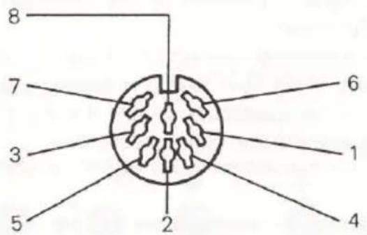
● Function between contacts
| Close contact | Functions |
| 1 & 82 & 8 | Focus to FARto NEAR |
| 3 & 84 & 8 | Zoom to WIDeto TELE |
| 6 & 8 | Auto Focus |
| 7 & 8/1 & 8 ※7 & 8/2 & 87 & 8/6 & 8 | Function keysBaselight ON/OFFUpper lighting ON/OFFInput selection[Internal→AV1→AV2] |
5 No Use (OPEN)
8 COMMON
※ 7 & 8/1 & 8 means, close contact #1 & #8 with close contact #7 & #8.

- Optional remote control
Elmo wired remote control RC-551, or Elmo wireless remote control RCW-552 are optionally available. However, please note that "Zoom size preset" of the remote control does not function when using with EV-400AV.
RS-232C SPECIFICATIONS
The Visual Presenter can be operated with the personal computer (IBM/PC or compatible) with connecting it to the RS-232C terminal.
○Set up
-
Connect the Visual Presenter to the personal computer with the RS-232C connection cable (Optional). Refer to the following connection diagram. When using a commercially available RS-232C cable, make sure that it is connected as described below.
-
Start the personal computer to set the RS-232C mode same as that of the communication mode of the Visual Presenter. Refer to the instruction manual of the personal computer for setting the RS-232C mode.
-
Set the transmission speed same as that of the personal computer. Then turn the power ON.
-
Start the program of the personal computer to operate the Visual Presenter. Then open the communication line.
-
Controlling with RS-232C starts. Note: Make sure to take the above steps for communication control.
○Cable connection
Visual Presenter (DSUB-9P)
IBM/PC or compatible (DSUB-9P)

Note: If the connector cable is not correctly connected to the Visual Presenter and personal computer, no answer is obtained.
Connect the connector cable correctly with screws for operation.
○RS-232C connector specification (DSUB-9P)
| Pin No. | Code | Direction of data Visual Presenter PC | Comments |
| 1 | CD | — | CD : Carrier Detect |
| 2 | RXD | ← | RXD : Received Data |
| 3 | TXD | → | TXD : Transmitted Data |
| 4 | DTR | → | DTR : Data terminal Ready |
| 5 | SG | — | SG : Signal Ground |
| 6 | DSR | ← | DSR : Data Set Ready |
| 7 | RTS | → | RTS : Request To Send |
| 8 | CTS | ← | CTS : Clear To Send |
| 9 | RI | — | RI : Ring Indicator |
○Transmission mode
Half duplex start-stop sync. mode
Start bit : 1 bit
Data bit : 8 bit
Stop bit : 1 bit
Parity bit : none
X parameter : none
Baud rate
(Transmission speed) : 600, 1200, 2400, 4800 bps.....DIP-SW selection
○RS-232C terminal and DIP-SW position

DSUB-9P (female)
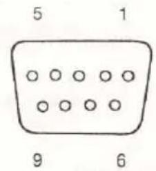
Receptacle side
Baud Rate Setting (DIP-SW selection)
| Baud Rate | SW-1 | SW-2 |
| 600 | OFF | OFF |
| 1200 | ON | OFF |
| 2400 | OFF | ON |
| 4800 | ON | ON |
*Factory set at: 4800 bps
Viewed from rear panel
○LIST OF TRANSMISSION COMMANDS
| Function | Command | Parameter | Data | Comments |
| Lighting | PL | OFF=0BASE=1UPPER=2 | ☐ ☐ | |
| Input Selection | AV | INT=0AV1=1AV2=2 | ☐ ☐ | |
| Auto Focus | AF | 0 | ☐ ☐ | |
| Focus(Analog control) | MF | NEAR=+FAR=- | ☐ ☐ | |
| Focus(Digital control) | FO | NEAR=+FAR=-OFF=0 | ☐ ☐ | Focus control. |
| Zoom(Analog control) | MZ | TELE=+WIDE=- | ☐ ☐ | |
| Zoom(Digital control) | ZO | TELE=+WIDE=-OFF=0 | ☐ ☐ | Zoom control. |
| Nega/Posi | NP | POSI=0NEGA=1 | ☐ ☐ | |
| Color/B&W | CB | COLOR=0B&W=1 | ☐ ☐ | |
| Default | DF | 0 | ☐ ☐ | Initialize mode reset. |
| Status request | QS | 0 | ☐ ☐ | |
| ROM Version | QR | 0 | ☐ ☐ | ROM Version request. |
| Acknowledge check | SA | OFF=0ON=1 | ☐ ☐ | Select each command acknowledge. |
| Add CR command | SC | OFF=0ON=0 | ☐ ☐ | Add CR command after the acknowledge. |
Note: "☐ ☐" means transmitting SPACE [20H] twice.
○DATA FORMAT SPECIFICATIONS
This command is in accordance with the form of 1-command/1-packet. The next key input is not received until the one processing is executed.
● File open and file close
Communication will be carried out in ASCII code according to the following format.
ENQ [05H] : Inquiry for connecting the line (PC→Visual Presenter)
ACK [06H] : Sent upon normal acknowledgment (Visual Presenter→PC)
NAK [15H] : Sent upon negative acknowledgment (Visual Presenter→PC)
EOT [04H] : Sent upon end of the line (PC→Visual Presenter)
ACK [06H] : Sent upon normal acknowledgment (Visual Presenter→PC)
Serial communication line reset.
Push both [UPPER] lighting button and [BASE] lighting button, then serial communication line will be reset, terminal (Visual Presenter) will sent the DC1 signal to host computer.
● Transmit format (PC→Visual Presenter)
[STX]
02H
command
□ □
parameter
□
data
□ □
2×20H
[ETX]
03H
Notes:
-
Make sure that the transmit format starts with STX (Start of Text) and ends with EXT (End of Text).
-
If the transmit format or command name is wrong, NAK (Negative Acknowledgement) is sent from the Visual Presenter as a result of failing to receive correctly.
-
If the send format is correctly sent, the Visual Presenter sends ACK (Normal Acknowledgement).
● Response data format
- Status request format
[STX]
□
02H
Lighting
□
Input Selection
□
Nega/Posi
□
Color/B&W
□
[ETX]
□
03H
example: each data will be corresponded with each command parameters.
- ROM version
[STX]
□
02H
□
□
□
□
□
□
[ETX]
□
03H
TROUBLE SHOOTING HINTS
| Symptom | Possible Cause/Countermeasure |
| No Images on TV monitor | ·Cable is not properly connected to the video-in terminal of monitor.·The power cord is disconnected from the wall AC outlet.·The plug is disconnected from the outlet.·Power is not turned on.·Zoom is set at Tele to display only white part of the material. |
| Out of focus | ·The object is too close to the lens. Check if it does not stand higher than 10cm from the stage surface.·The 3-D object is not focused unless the sub column (camera head) is extended.·The object on the stage is not focused if the close-up lens is removed from the camera head.·Zoom is set at Tele after focusing at Wide angle.Focus on the point of max. Tele.·It is difficult to automatically focus on such objects as referred on page 15. |
| The lamp is not quickly turned on. | ·This is caused by the built-in safety circuit for protecting the lamp. This is not a fault. |
| Image is too dark. | ·The iris control knob (IRIS) is set at dark side (CLOSE).·The illumination is not sufficient. Use the lighting unit. |
| Input selection can not be made. | ·Inputting to S-video while connecting output of C-video to the monitor or vice versa. |
| The playback image is stripped looking. | This is caused by the interference strips between the dot of printed material and the scanning line. This is not a fault. |
| Flickers on TV monitor. | Set the shutter speed to 1/100 to reduce flickers. |
*If trouble still persists even after checking the above, consult your dealer or an authorized Elmo service center.
SPECIFICATIONS
General
| Power source | : 120V AC 60Hz |
| Power consumption | : 35W |
| AC outlet | : Provided 1 pce max. 400W (3.2A)/Unswitched |
| Outside dimensions | : 690mm (W) 545mm (D) 653mm (H) -when set up450mm (W) 545mm (D) 203mm (H) -when folded |
| Weight | : 8.5kgs |
| Optics | |
| Lens | : F1.4~2.1, f=8.5mm~68mm |
| Shooting area | : 320mm×240mm max. (WIDE·Scan100%) |
| Limit of focus adjustment | : at the range of stage surface~10cm from the stage surface (with column extended position and with close-up lens)∞~1.2m (without close-up lens) |
| Zoom | : Powered |
| Focusing | : Auto/manual |
| Iris | : Auto/manual (with fine adjustment) |
| Lighting | |
| Upper lighting unit | : High frequency lighting method. Fluorescent lamp 6W×2,(type: FHL6EX-N/CODE #9356) |
| Built-in baselight | : High frequency lighting method. |
| Video | |
| Television system | : NTSC compatible |
| Image pick-up element | : 1/2" Interline-transfer CCD |
| Picture element | : 811 (H)×508 (V) |
| Sync.system | : Internal/External sync. (automatic changeover) |
| Resolution | : More than 450 TV lines (Y signal with horizontal)More than 350 TV lines (Vertical) |
| S/N ratio | : 46 dB |
| Output signal | : C-video VBS 1.0 Vp-p/75Ω unbalancedS-video Y 0.714 Vp-p/75Ω unbalancedC 0.286 Vp-p/75Ω unbalanced |
| Ext. sync. input condition | : C-video VBS (75Ω unbalanced)Sync: 0.286V±0.1V, Burst: 0.286V±0.1V |
| Ext. sync. frequency range | : (against NTSC standard) H±20ppm, SC±50ppm |
| H-phase adjustment | : Manual (0~8μs) |
| SC-phase adjustment | : Manual (0~360°) |
| Electronic shutter | : 1/60 sec. or 1/100 sec. |
| White balance | : Full auto/Manual |
| Nega/posi conversion | : Built-in (C-video, S-video) |
| Color/B & W selection | : Built-in (C-video, S-video) |
| Input selection | : 3 systems (Internal/AV1/AV2) |
| Input terminal | : C-video input (RCA jack/75Ω unbalanced)×2S-video input (Mini DIN 4P connector/75Ω unbalanced)×2Ext. sync. input (BNC connector/75Ω unbalanced)×1Mic. input (Φ6.3mm jack/applicable impedance 600Ω, -65dB)×1Audio input (RCA jack/applicable impedance 10KΩ or more,-10dB)×2 |
| Output terminal | : C-video output (RCA jack/75Ω unbalanced)×1(BNC connector/75Ω unbalanced)×1S-video output (Mini DIN 4P connector/75Ω unbalanced)×1Audio output (RCA jack/applicable impedance 10KΩ or more,-10dB)×1 |
| Ext. control terminal | : RS-232C (DSUB-9P)×1Manual remote (DIN 8P)×1 |
| Supplied accessories | Power cord ×1Video-audio cable ×1Close-up lens (Adapter Lens AC2) ×1Operation manual ×1Dust Cover ×1 |
*The design and specifications are subject to change without prior notice. Weight and dimensions are approximate.
WARNING:
■Unauthorized recording of copyrighted film/materials may infringe on the rights of copyright owners and be contrary to copyright laws.
ELMO
ELMO CO., LTD.
6-14, Meizen-cho, Mizuho-ku,
Nagoya,467-8567,Japan
OVERSEAS SUBSIDIARY COMPANIES
U.S.A.
Elmo Mfg. Corp.
1478 Old Country Road,Plainview,NY
11803-5034
Tel.(516)501-1400 Fax.(516)501-0429
21720 Nordhoff Street, Chatsworth, CA 91311-5826
Tel.(818)346-4500 Fax.(818)998-4186
Canada
Elmo Canada Mfg.Corp.
44 West Drive, Brampton, Ontario, L6T 3T6
Tel.(905)453-7880 Fax.(905)453-2391
Germany
Elmo (Europe) G.m.b.H.
Karl-Rudolf-Str. 178,
40215 Düsseldorf
Tel.(0211)376051 Fax.(0211)376630
Printed in Japan
6X1VIEN02 R3(A)

- IMPORTANT SAFEGUARDS
- WARNING:
- INFORMATION
- INTRODUCTION
- BEFORE YOUR USE
- CONTENTS
- PART NAMES AND FUNCTIONS
- ○Rear Panel
- SETTING UP
- CONNECTION TO MONITOR TV
- ○Connection to composite video-in terminal
- ○Connection to S video-in terminal
- OPERATING PROCEDURES
- ○Simple steps for presenting printed materials
- ○Simple steps for viewing transparencies as slide film
- ○For use as a conventional video camera
- STOWING
- VARIOUS FUNCTIONS
- ○Lighting
- ○Input selection
- ○Nega/posi conversion
- ○Color/B&W selection
- ○Zoom
- ○Focus
- Auto Focus
- Powered Manual Focus
- ○White balance
- Full-Auto mode:
- Manual mode
- Electronic shutter speed
- ○Iris
- ○Microphone
- ○LCD monitor shoe
- EXTERNAL SYNC. ADJUSTMENT
- ● Horizontal sync. phase adjustment
- ● Sub-Carrier Phase Adjustment
- MANUAL REMOTE
- - Optional remote control
- RS-232C SPECIFICATIONS
- ○Set up
- ○Cable connection
- ○Transmission mode
- ○RS-232C terminal and DIP-SW position
- ○DATA FORMAT SPECIFICATIONS
- ● File open and file close
- Serial communication line reset.
- ● Transmit format (PC→Visual Presenter)
- Notes:
- ● Response data format
- SPECIFICATIONS
- ELMO CO., LTD.
- OVERSEAS SUBSIDIARY COMPANIES
Brand : Elmo
Model : EV-400AF
Category : Projector