
MP-50E - Projector Elmo - Free user manual and instructions
Find the device manual for free MP-50E Elmo in PDF.


| Product Type | Multimedia LCD Projector with Document Scanner |
| Model Number | MP-50E |
| Brand | Elmo (formerly Avio) |
| Display Technology | 3 x 1.0" Poly-Silicon TFT Active Matrix LCD with Micro Lens Array |
| Native Resolution | 1024 x 768 (XGA) |
| Brightness | 3000 ANSI Lumens |
| Projection Lens | Manual Zoom (1-1.25x), f=36.5-45.6 mm, F1.7-2.2 |
| Light Source | 260W Super High-pressure Mercury Lamp (Model MPLU-50) |
| Lamp Life | Target replacement at 1400 hours, forced shutdown at 1500 hours |
| Scan Area (OHP Mode) | 216 mm x 288 mm (8.5" x 11.3") |
| Scanner Camera | 2 Megapixel Single-array Color CCD |
| Projected Image Size | 32" to 300" diagonal (1.4 m to 13.9 m projection distance) |
| Color Reproduction | Full color, 16.77 million colors |
| Input Signals (PC) | Analog RGB: 15-pin Mini D-sub x2; supports up to 1600x1200 (compressed) |
| Input Signals (Video) | Composite RCA, S-Video (Mini DIN-4); NTSC/PAL/SECAM |
| Audio | Stereo 1W x2 speakers; PC audio mini-jack x2, RCA video audio x1, audio output mini-jack |
| Keystone Correction | Digital keystone adjustment (horizontal and vertical) |
| Internal Memory (Stored Images) | Up to 8 pages of OHP images |
| Power Supply | 100-120 V / 220-240 V AC, 50/60 Hz |
| Power Consumption | 390W (100-120V), 370W (220-240V) |
| Dimensions (W x D x H) | 400 mm x 315 mm x 145 mm (15.7" x 12.4" x 5.7") |
| Weight | 7.3 kg (16.1 lbs) |
| Operating Temperature | 0°C to 35°C (32°F to 95°F) |
| What's in the Box | Projector, Remote Control (with AA batteries), Power Cord (2 types), PC Signal Cable, Lens Cap, User's Manual |
| Safety Features | Thermal protection, lamp cover interlock, auto power-off, air filter |
Frequently Asked Questions - MP-50E Elmo
User questions about MP-50E Elmo
0 question about this device. Answer the ones you know or ask your own.
Ask a new question about this device
Download the instructions for your Projector in PDF format for free! Find your manual MP-50E - Elmo and take your electronic device back in hand. On this page are published all the documents necessary for the use of your device. MP-50E by Elmo.
USER MANUAL MP-50E Elmo
Multi-Function LCD Projector MP-50E
User's Manual
English
Deutsch
Français
Española
Thank you for purchasing the Avio MP-50E LCD Projector.
Please read this manual carefully in order to use the projector properly.
After reading this, please keep it in a safe place together with the warranty sheet.
● Features
- Three handy features in a single body. The projector for the multimedia age
- Documents, catalogs and other printed matter can be projected directly from the scanner. This frees the user from the need to make OHP film inserts for each document.
- Personal computer screens can be projected. This allows the user to make detailed presentations using information on a personal computer.
- Videos and DVD images can be projected as they are. This aids the user in making visually appealing presentations.
- Easy-to-understand and simple operation
Projection of printed matter, personal computer screens and video images can be selected at the push of a button.
• High cost effective resource-saving design
OHP film inserts no longer need to be made, which saves wasted time and expense.
- "Super-Slim" Stylish Body
Full OHP functions based on advanced technology built in to a super-slim chassis. It fits anyplace, when you're using it, and when you need to put it away.
• Expressive color images
The projector is equipped with a high-resolution 2 million pixel single-array color CCD camera. This allows subtle midtones in color documents to be reproduced faithfully and sharp as projected images in full color (16,770,000 colors).
- Enlarged display without changing the size of the projected image
When projecting documents such as catalogs and word-processor documents containing small text that have not been made specially for presentations, the document can be enlarged without changing the size of the projected image for easier viewing.
• Provided with display functions for compressed or enlarged PC screen
Screens of resolution more than 1024 x 768 dots are displayed compressed to 1024 x 768 dots without any loss in character quality. Lower resolutions such as 640 x 480 can also be enlarged to 1024 x 768 dots.
● About Trademarks
IBM and PC/AT are trademarks or registered trademarks of International Business Machines Corporation.
Macintosh and Power Book are trademarks of Apple Computer Inc. Windows is a trademark of U.S. Microsoft Corporation.
Warnings and Safety Precautions
● Warning Symbols
To alert the user to important safety precautions, the following symbols are used in this manual and on the product. Make sure you understand what these symbols mean before operating the projector.


: Death or serious injury may result if this warning is ignored.
: Injury or damage to the equipment may result if this warning is ignored.
: This indicates an item that you should take care of when handling your projector.
: This symbol alerts the user to high voltage that could cause electric shock.
● Safety Precautions
WARNING
- If a fault occurs:
- If you detect smoke, or a strange smell or sound, immediately disconnect the power cord. It is dangerous to continue using the projector after a fault occurs. Return the projector to the dealer where it was purchased for repair.
- Avoid placing the projector near dangerous substances.
- Make sure that no metallic or flammable material can get into the projector through the air vents.
- Do not place any objects containing water on top of or next to the projector.
- If foreign matter gets inside the projector:
- If foreign matter such as water or metal gets inside, immediately disconnect the power cord.
It is dangerous to continue using the projector when foreign matter gets inside. Return the projector to the dealer where it was purchased for servicing.
- Do not remove the cabinet.
- Do not remove the cabinet. There are high-voltage components inside and touching these parts could cause electric shock, or damage the equipment.
- Handle the power cade safely.
- Do not place any heavy objects on top of the power cord. Damage to the power cord can cause wire breakage, fire, or electric shock.
- Do not pull the power cord when disconnecting the power plug. Pulling the cable may break the wires or cause fire or electric shock. Always hold the plug itself when pulling it out of the power outlet.
- Do not damage the power cable. If the power cord is damaged (e.g. the core is exposed or cut), contact the sales office of purchase.(charged) it could cause fire or electric shock if you continue using the damaged power cord.
- Do not look through the lens.
- Do not look through the lens into the projector during operation. The powerful rays passing through the lens could damage the eyes.
- Do not put the projector in unstable places.
- Do not put the projector in unstable places such as on unstable desks or slopes. Doing so could cause the projector to drop or turn over, resulting in injury.
- Do not use any voltages other than specified.
- Do not use any voltages other than specified. Doing so could cause fire or electric shock.
- Do not disassemble the alkaline batteries
- Do not short-circuit, disassemble, or burn the alkaline batteries. Doing so could cause the alkaline solution to leak, which could cause eye injury, as well as cause a fire or damage the surrounding area due to heat or explosion. If the alkaline solution touches skin or clothes, wash them with clean water. If it get into eyes, immediately wash them with clean water and see a doctor.
- Do not bump the glass surface
- Do not bump the glass surface over the scanner. Doing so may break the glass, resulting in injury.
- Do not touch the air vents or lamp cover
- The air vents, lamp cover, and peripheral surfaces may be hot during operation or just after the light is turned off. Do not touch those for a long time.
- Do not block the lens front
- Do not block the lens front during operation. The powerful rays passing through the lens may cause fire or burns if you put anything in front of the lens or block the lens with your hand during operation.
CAUTION
- Installation
- A void installing the projector in places where it may be exposed to:
- Strong vibrations
- Soot or steam
- Direct sunlight or near a heater (35°C/95°F or higher)
- High humidity or dust
- Extreme cold (0°C/32°F or lower)
- W obbling on an unstable surface
- Strong magnetic or electric field generated from a nearby appliance
- Do not block the air vents.
- Do not block the air vents with cloth or an object. When you put anything around the unit, be sure to ensure a space of 10cm / 4 inches or more between the unit and the air vent. Be sure to prevent paper or cloth from blocking the air vent at the bottom of the unit. If blocked, the internal temperature may increase, resulting in malfunctions.
- Do not bump the projector.
- A v oid bumping the projector when moving or handling. Shocks can cause damage.
• Care of the projector
- To prevent risk of accidents, always disconnect the power plug before cleaning the projector.
- Clean the lens surface with a commercial blower or lens cleaning paper.
Wiping with tissue paper or a handkerchief can damage the lens.
- T o clean the cabinet, operation panel, and glass surface, wipe gently with a soft cloth. For particularly dirty spots, soak the cloth in a neutral detergent mixed in water, wring out well and wipe off the dirt, then use a dry cloth to wipe dry.
- Do not wipe the projector with any volatile solvent such as benzine or thinner.
Solvents can cause surface deformation or flaking of the paint.
If using an impregnated cloth, follow the instructions.
- Avoid scratching the glass surface.
- T ake care not to scratch the glass surface of the scanner with hard or pointed objects.
Scratches on the glass may distort the projected image.
- Batteries
- When inserting batteries in the remote control, note the polarity (plus and minus signs) and insert correctly as indicated. Inserting a battery in a wrong direction can cause rupture or leakage, and could result in fire and injury or soil the surrounding area.
- Do not use batteries other than the type specified for the equipment. Do not use a new battery and an old battery together. Incorrect battery usage could result in rupture or leakage, and could cause fire and injury.
- Do not heat, break open, burn, or immerse the batteries. Battery rupture or leakage could cause fire and injury.
• Servicing and cleaning
- Have the internal components cleaned by a retailer about once a year. There is a risk of fire or faulty operation if the inside of the projector gets dusty and is not cleaned for a long time. For best results, the projector should be serviced before the wet season brings damp conditions. Cleaning charges are at the discretion of the retailer.
- If not using the projector for a long period:
- If you do not plan to use the projector for a long time, disconnect the power cord for safety.
- Disposal
- Follow the recommendations of your local authority when disposing of the projector.
- Transporting the projector
- Use the special packaging when transporting the projector. The manufacturer cannot accept responsibility in the event of damage or accident if other packaging is used.
- Use the special packaging no more than two times. Repeated usage reduces the shock absorbency of the packaging and can lead to damage or accident.
- Contact the retailer if you require new packaging.
- Lamp implosion
- An AC type New Super High pressure lamp is used in this projector and it is rare for the lamp to explode during use. The lamp is also designed to forcibly turn off because there is a high possibility that the lamp will break if it is used beyond the lamp usage of 1500 hours (Refer to pages E-54 and E-55).
Note the following things
- A noise occurs because the internal pressure of the New Super High pressure lamp gets extremely high.
The unit is designed so that no pieces of glass come out of it when the lamp explodes. - However, the gas inside of the lamp can escape and looks like white smoke. It will not cause any fire.
Remedy
- If a lamp explodes in a product, there will be pieces of lamp inside. Do not replace the lamp. Return the product to the sales office or agent of purchase. Even though the lamp has exploded, never try to replace the lamp by yourself. The lamp pieces could cause injury.
- Replacing the lamp
- Be sure to turn the lamp off and disconnect the power cord when the fan stops, and wait an hour or more before replacing the lamp.
Replacing the lamp during operation or just after the power is turned off may cause burns due to heat.
Refer to "Lamp Unit Replacement" on page E-54 for the procedure.
- Replacing / cleaning the air filter
- Be sure to disconnect the power cord when the cooling fan stops before removing the air filter.
Removing the air filter while the cooling fan is rotating could cause a burn. Refer to “Cleaning the Air Filter” on page E-56 for the procedure.
- Avoiding malfunctions and accidents
- Adjust the Adjustable feet to keep the projector horizontal.
Using the projector in a tilted status may cause injury if it turns over. Refer to "Adjusting the Tilt" on page E-18 for the adjusting procedure.
- Do not disassemble the manganese batteries
- Do not short-circuit, disassemble, or burn the manganese batteries.
Doing so could cause the batteries to generate heat or explode due to the leaked solution, resulting in fire, injury, or damages to the surrounding area.
- Do not do the followings
- Do not put anything heavy on the projector.
- Do not step on the projector, rack, or stand. Do not hold or hang on the projector.
Doing so could cause the projector to turn over or break, resulting in injury. Especially be careful if small children are near.
- Do not use the rack unless the casters are locked when placing the projector on a rack with casters. Doing so may cause the projector to move or turn over, resulting in injury.
- Do not turn the lamp on/off within one minute after it is turned off/on. Extremely high voltage is generated in the lamp just after it is turned on. Turning the lamp on/off too frequently could cause the lamp to deteriorate or break, resulting in malfunctions of the projector.
- Do not project an image with the lens cap attached.
- Moving the projector
- Be sure careful of the glass surface when moving the projector while holding the handles with both hands.
- If not inserted fully, the materials cover may get loose and fall off while you carry it.
- Care of the power cord and plug
- Do not put the power cord near a heater.
Doing so could cause the sheath of the cable to melt down, resulting in fire or electric shock. - Do not connect or disconnect the power cord with wet hands. Doing so could cause electric shock.
- Be sure to pull out the power cord and disconnect any cable connections between units and release the anti-theft lock before moving the projector. Moving the projector with cables connected may cause fire or electric shock if the cables are damaged.
- If you do not plan to use the projector for a long time, disconnect the power cord for safety.
- DO NOT REMOVE ANY SCREWS except the lamp cover screw and two lamp unit screws. You could receive an electric shock.
What's in the Box?
Make sure your box contains everything listed. If any pieces are missing, contact your dealer. Please save the original box and packing materials if you ever need to ship your MP-50E Projector.
MP-50E Projector (1)
Remote control(1)
Power codes (2)

For North America
Three-pin type for U.S.A and Canada;

For Europe
Two-pin type for Europe.
PC Signal cable (1)
Lens cap(1)
Batteries(2) (AA×2)
Documents:
User's manual (1)
Contents
Part Names and Functions....E-9
Projector E-9
Terminal Panel E-11
Buttons and Indicator Lights E-12
Remote Controller E-15
Remote Control Operations E-17
Battery Replacement E-17
How to Install the Projector .... E-18
Installation Sequence ...... E-18
Adjusting the Tilt E-18
Projection Distance and Projected Image Size.... E-19
Typical Installation.... E-20
Compensating Keystone E-21
Connecting to a Personal Computer ...... E-22
Connecting to a Personal Computer E-22
About RGB Video Output E-23
When Images on the Personal Computer Screen are not Projected E-24
Input Signal Compatibility Table (PC video input terminal) E-25
Connecting to a Video Source or DVD Player.... E-28
Basic Operation E-29
Preparation E-29
Basic Operations in the OHP Mode E-30
Basic Operation of PC or Video Input E-37
How to Quit E-41
Performing Various Adjustments.... E-42
Menu Structure E-42
Description of Menu Items E-43
Basic Operation E-47
Quick Menu E-51
Description of Menu Items ...... E-51
Maintenance E-52
Fault Protection....E-52
Lamp Unit Replacement E-54
Cleaning the Air Filter E-56
Troubleshooting ...... E-57
Repair Service.... E-58
Specifications ...... E-59
Part Names and Functions
Projector
Handle
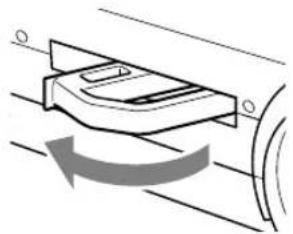
■ Extended
Press lightly on the left side of the handle and it rotates 180° and comes out.
natural_image
Diagram of a mechanical component with rotational motion indicated by arrows (no text or symbols)Retracted
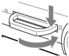
Rotate the handle while pressing on its right side to store it.
natural_image
Diagram of a mechanical component with directional arrows indicating motion or force (no text or symbols)Materials Cover
The scanner and printed matter is located under this cover.
See page E-31.
Operation panel
Buttons for operating the projector are located here.
See page E-12.
Speakers
Remote Control Sensor
Adjustable Feet
Focus adjuster
Turn this to adjust the focus. See page E-30.
Projection Lens
Images are projected through this lens. * Be sure to remove the lens cap when projecting images.

Air Vent A (air filter) (side of main unit)
Air is taken in through this vent. An air filter is provided to prevent dust from getting inside the projector.
See page E-56.
Anti-theft Lock
See the NOTE below.
Tilt Adjustment Buttons
Press this to adjust the adjustable feet. See page E-18.
Adjustable Feet
These feet are for adjusting the tilt angle as well as the left and right balance of the projected image. Turning them counterclockwise raises the main unit, and turning them clockwise lowers the main unit.
See page E-18.
Zoom lever
Turn this ring to adjust the screen size. See page E-30.
NOTE
About the anti-theft lock

The anti-theft lock is compatible with Kensington security cable lock.
Contact the following for more information about the products.
Kensington Technology Group
Lamp Unit Cover
(bottom of main unit)
The scanner lamp unit is housed inside this cover.
See page E-54.
■ Terminal Panel

natural_image
Diagram of an electronic device showing internal components and a directional arrow (no text or symbols)
| 1PC Video Input | Input terminal for the PC analog RGB signals. Two personal computers can be connected. |
| 2PC Audio Input | Audio input terminal for a PC (stereo compatible). Two personal computers can be connected. |
| 3RGB Video Output | When OHP is selected, OHP images are output. When PC/VIDEO input is selected, input PC video is output as it is. During standby, RGB-IN1 images that are input from the personal computer are output directly. |
| 4Test (maintenance) | This exclusive terminal is used when performing maintenance and in-house tests. It cannot be used for other connections. |
| 5Audio Output | Audio output terminal for MP-50EThis terminal outputs audio (either from the PC or video source) that is currently being input. In the standby mode, PC audio is output.When OHP input is selected, PC audio is output. |
| 6S-VIDEO Input | Input terminal for video source (Y/C) |
| 7Video Source Video Input | Input terminal for video source (NTSC/PAL/SECAM) |
| 8Video Source Audio Input | Audio input terminals for a video source (stereo compatible) |
■ Buttons and Indicator Lights

| Name | Description | Page to see | |
| 1 | POWER Button | Press this button to turn the lamp on or off.Only this button can be used when the lamp is off. | E-20, 29, 41 |
| 2 | TEMP LED | This LED blinks for ten seconds and lights when the temperature inside the projector has built up. | E-52 |
| 3 | LAMP/COVER LED | This LED lights while the lamp is on.When the lamp is turned on, it blinks for about six seconds then remains on.When the lamp is off, it blinks for about 60 seconds then remains off.This LED blinks when the lamp fails to light. (The LED blinking pattern in this case is longer than other instances.)Blinks when the lamp usage time exceeds 1400 hours, it remains on after lamp usage time exceeds 1500 hours.Lights when the air filter cover or the lamp unit cover is not in place. | E-29E-41E-54E-54, 56 |
| 4 | ON/STANDBY LED | This LED lights (red) in a standby state, and lights (green) when the lamp is on. | E-29, 41 |
| 5 | INPUT SELECT Buttons(OHP, PC1/PC2, VIDEO) | Press this button to switch the input screen.When PC is selected, images from the PC input terminal are projected; when VIDEO is selected, images from the video source input terminal are projected; or, when OHP is selected, an image of the printed matter or document placed on the scanner on the main unit is projected.Pressing on the PC1/PC2 button when PC input is selected switches between PC input 1 and PC input 2. | E-29 |
| 6 | KEYSTONE Button | Press this button to compensate keystone. | E-21 |
| 7 | MUTE Button | Press to stop projecting the image without turning off the lamp. Press it again and the image will reappear. | E-34, 40 |
| 8 | BRIGHTNESS Buttons | These buttons adjust the brightness. Pressing the button darkens the projected image, and pressing the button lightens the projected image. | E-31, 37 |
Part Names and Functions
| 9ZOOM Buttons | These buttons adjust the zoom ratio. Pressing thebutton reduces the image, and pressing thebutton enlarges the image. | E-32, 38 |
| 10MENU Button | Display the menu display. | E-42 |
| 11SCROLL Button | Set and select the variable and adjustable values on the menu display.Move the zoom position when using the zoom display.Move the pointer when the pointer is displayed. | E-47E-32, 38E-34, 38 |
* Once a menu or an adjustment is displayed, their display automatically disappears, and adjustment values are stored to memory if buttons are not operated for about 30 seconds.
* F or details of menu adjustment, see page E-43 onwards.
■ Buttons and Indicator Lights

| Name | Description | Page to see | |
| 12 | RESIZE Button | Press to change the size of the projected image when OHP is selected.Press to do automatic synchronous adjustments when PC is selected. | E-33E-38 |
| 13 | POSITION Buttons | Press to change the orientation of the projected image when OHP is selected. Press the button to reverse the top and bottom of the projected image. Press the button to switch between vertical display and horizontal display. | E-31 |
| 14 | LIVE IMAGE Button | Press to confirm the projected image while moving the document when OHP is selected. | E-32 |
| 15 | SET/POINTER Button | Press this button to apply a menu item in the menu display.Display the pointer when the menu display is not displayed. Press it again to hide the pointer. | E-48E-34, 38 |
| 16 | OHP STORED IMAGE/VOLUME Buttons | A maximum of eight pages of images are stored to internal memory when the display is refreshed, when OHP is selected. Press to access those images.Adjust the volume when PC or video is selected. Press the button to reduce the volume. Press the button to increase the volume. | E-33E-39 |
| 17 | REFRESH/FREEZE Button | Press to refresh the projected image when OHP is selected. Press it again to refresh the projected image if you have switched or moved the document.Press to freeze the projected image when PC or video is selected. | E-32E-39 |
Remote Controller

| Name | Description | Page to see | |
| 1 | POWER Button | Press this button to turn the lamp on or off.Only this button can be used when the lamp is off. | E-20,29,41 |
| 2 | POINTER TYPE Button | Press this button to select a pointer type. | E-34,39 |
| 3 | POINTER/SET Button | Press this button to apply a menu item in the menu.Display the pointer when the menu is not displayed. Press it again to hide the pointer. | E-48E-34,38 |
| 4 | SCROLL Button | Set and select the variable and adjustable values on the menu display.Move the zoom position when using the zoom display.Move the pointer when the pointer is displayed. | E-47E-32,38E-34,38 |
| 5 | MUTE Button | Press to stop projecting the image without turning off the lamp. Press it again and the image will reappear. | E-34,40 |
| 6 | MENU Button | Press this button to display the menu display, or select menus. | E-42 |
| 7 | REFRESH/FREEZE Button | Press to refresh the projected image when OHP is selected. Press it again to refresh the projected image if you have switched or moved the document.Press to freeze the projected image when PC or video is selected. | E-32E-39 |
| 8 | RESIZE Button | Press to change the size of the projected image when OHP is selected.Press to do automatic synchronous adjustments when PC is selected. | E-33E-38 |
| 9 | INPUT SELECT Buttons (OHP, PC1/PC2, VIDEO) | Press this button to switch the input screen.When PC is selected, images from the PC input terminal are projected; when VIDEO is selected, images from the video source input terminal are projected; or, when OHP is selected, an image of the printed matter or document placed on the scanner on the main unit is projected. | E-29 |
| 10 | in P Button | Press to display the image from the video source that is connected in a window on the lower right side of the projected image when PC selected. | E-40 |
| 11ZOOM Buttons | These buttons adjust the zoom ratio. Pressing thebutton reduces the image, and pressing thebutton enlarges the image. | E-32, 38 |
| 12POSITION Buttons | Press to change the orientation of the projected image when OHP is selected. Press thebutton to reverse the top and bottom of the projected image. Press thebutton to switch between vertical display and horizontal display. | E-31 |
| 13BRIGHTNESS Buttons | These buttons adjust the brightness. Pressing thebutton darkens the projected image, and pressing thebutton lightens the projected image. | E-31, 37 |
| 14VOLUME Buttons | Adjust the volume when PC or video is selected. Press thebutton to reduce the volume. Press thebutton to increase the volume. | E-39 |
| 15OHP STORED IMAGE Buttons | A maximum of eight pages of images are stored to internal memory when the display is refreshed, when OHP is selected. Press to access those images. | E-33 |
| 16KEYSTONE Button | Press this button to compensate keystone. | E-21 |
| 17LIVE IMAGE Button | Press to confirm the projected image while moving the document when OHP is selected. | E-32 |
■ Remote Control Operations
- Use the remote control within about seven meters (7.7 yards) from the remote control sensors (on the front and rear sides) of the projector and within 10 degrees to the left and right. This distance may become shorter as the battery wears down.
- The remote controller does not work if there are obstacles between the remote control and the remote sensor on the main unit.
■ Battery Replacement
natural_image
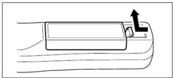
Line drawing of a car interior with a door and handle, showing an upward arrow indicating motion (no text or symbols)- Remove the battery compartment cover by pushing in the claw and lifting the cover up.

natural_image
Diagram of a remote control panel with battery and switch components, showing an arrow pointing to the internal structure (no text or symbols present)- Install two batteries in the battery compartment, making sure that they are aligned as indicated by the (+) and (-) marks.
natural_image
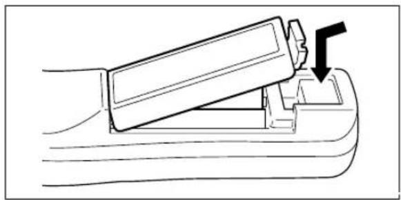
Line drawing of a hand using a tool to lift a component, showing a downward arrow (no text or symbols)- Return the battery compartment cover to its original position.
CAUTION
Handling the remote controller
- Do not subject the remote controller to such severe impact as dropping it on the floor. Doing so may damage it and cause it to cease functioning.
- Keep the remote sensor away from water. Wipe the remote controller immediately if it gets wet.
- Avoid heat or hot water. Remove the dry cells when you are not using the remote controller for a long period of time.
- Do not mix new and old dry cells, or use different types of dry cells at the same time.
- Do not disassemble or heat batteries, or throw them into a fire.
- F ollow your local government's disposal instructions for used dry cells.
- The remote controller may not work when it is used near inverter-driven equipment.
- The remote controller may not work or may work ineffectively when it is used near inverter-driven fluorescent lighting.
NOTE
- When replacing the batteries, buy AA batteries.
- Ni-Cad batteries or other chargeable batteries cannot be used. Use manganese batteries or alkaline batteries.
How to Install the Projector
■ Installation Sequence

flowchart
graph LR
    A["Check the installation site and image size."] --> B["Prepare the screen."]
    B --> C["Install the projector."]
    C --> D["Install the input devices."]
    D -.-> E["End"]
See "Projection Distance and Projected Image Size" on page E-19.
PC, video source, etc.
■ Adjusting the Tilt
The position and tilt angle of the projected image can be adjusted by adjusting the adjustable feet. Press both the left and right tilt adjustment levers to lift the main unit, and release them when the desired height is reached. You can fine-adjust the tilt by turning the bottom section of the adjustable feet. Turning this section counterclockwise raises the main unit, and turning it clockwise lowers the main unit. Also, you can adjust the tilt angle by turning the adjustable foot located on the rear left of the main unit.
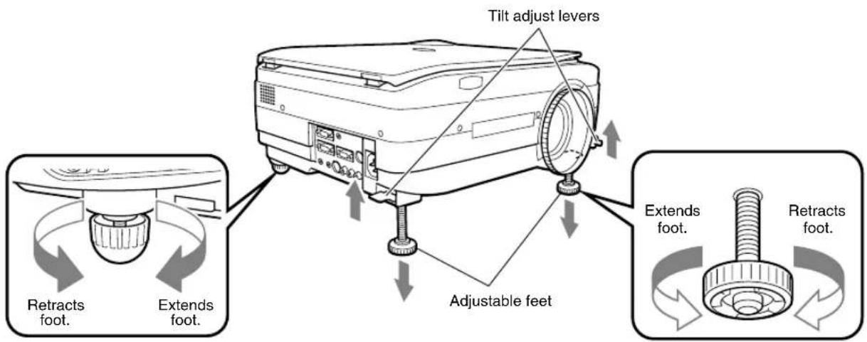
CAUTION
- Do not tilt the main unit at extreme angles by turning only one side of the adjustable feet. Doing so may cause the main unit to slip or fall down, resulting in accidents or failures.
- Vent A on the bottom of the main unit takes in air to cool the inside of the projector. As air is taken in by large suction force, cloth or paper may be sucked in against the vent. If this happens, the temperature inside may build up, and cause an accident or failure.
- The rubber feet may soil the installation surface depending on where the projector is installed.
■ Projection Distance and Projected Image Size
Use the following diagrams to determine the projected image size and the type of screen required for any given projector location.
- The projection distance that provides good focusing is 1.4 m (1.5 yd) to 13.9 m (15.2 yd) from the front of the lens. Install the projector within this range.


area
| Projection Distance (m) | Projected Image Size (inch) | | ----------------------- | --------------------------- | | 1 | 102 x 76 | | 3 | 203 x 152 | | 5 | 305 x 229 | | 7 | 406 x 305 | | 9 | 508 x 381 | | 11 | 610 x 457 | | 13.9 | 610 x 457 |Wide: The largest image that can be projected by adjusting the image with the zoom lens.
Tele: The smallest image that can be projected by adjusting the image with the zoom lens.

CAUTION
Installation location
- Do not install the projector in excessively hot or cold locations. The ambient temperature should be within 0^ to 35^ ( 32^ to 95^ ).
- Position the projector so that the screen does not directly receive sunlight or other light from other lighting. Otherwise, the projected image becomes white and is difficult to view. In a bright room, use a curtain or other means to darken the area around the screen.
- Do not install the projector where it will be subject to excessive humidity, dust, or cigarette smoke. Otherwise, image quality may deteriorate as dirt builds up on the lens, mirrors and other optical components.
- Do not install the projector in a small room with poor air circulation or any place where the air vents may be blocked. Temperature build-up inside the projector may result in fire or a failure. (Vents are located on the bottom and right side of the projector.)
■ Typical Installation

natural_image
Diagram of a mechanical device with a dashed line indicating alignment or projection, no text or symbols present1. Select the installation site
Place the projector on an even and stable surface such as a table.

natural_image
Diagram showing a cable being inserted into a socket, with connectors and a plug inserted (no text or symbols present)- Connect the power cord (supplied), and press the ○ button (or ⏻) button.)

- Turn the direction of the lens so that it is perpendicular to the screen.
Turn the unit to the left or right so that the top and bottom lines of the projected image are parallel.

- Adjust the adjustable feet to move the projected image to the desired height. (Adjust the tilt angle between 0^ to 7^ .)
The position of the projected image can be moved up or down by adjusting tilt.
■ Compensating Keystone
If the projected image is distorted, you can eliminate the distortion by doing keystone compensation.
● How to Compensate Keystone
Press the KEYSTONE button (or the KEYSTONE button on the remote controller) to display the "Keystone menu."
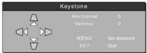
Keystone menu
Press the △ button to make the top of the projected image narrower.

Press the ▽ button to make the bottom of the projected image narrower.
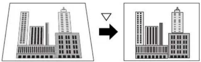
Press the ◀ button to make the left side of the projected image narrower.
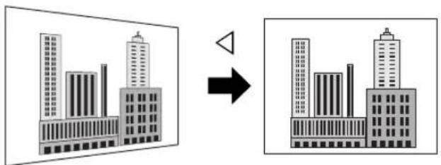
Press the ▷ button to make the right side of the projected image narrower.

Press the ○ button (or the Ⓞ button on the remote controller) to return to "0" (No compensation).
NOTE
- When keystone compensation is performed, the resolution at the edges of the projected image is reduced, making small characters difficult to read. To prevent this, place the projector on as level a surface as possible, and set the Keystone menu to "0" (No compensation).
- As image processing is performed for keystone compensation, displayed images (characters, etc.) are displayed slightly blurred when keystone compensation is used compared with when it is not used.
- When displaying an image with VGA resolution less than 640 x 480 pixels with a excessive horizontal keystone compensation may cause parts of the image to become fuzzy. See page E-25 for more information.
- The degree to which keystone compensation can be adjusted depends on the image signal.
- If the horizontal value is adjusted to its largest (or smallest) the vertical adjustment value can not be moved in the plus direction when doing keystone compensation.
Connecting to a Personal Computer

CAUTION
Cautions on Connection
- Before connecting other devices, turn off each device to protect the projector and other connected devices.
- For details of how to connect and use devices connected to the projector, refer to the User's Manual for each device.
- Sometimes images are not displayed on the screen properly when they are displayed on a notebook PC LCD as well. If this happens, turn the notebook PC display off to remedy this. The method for turning off a notebook PC display varies according to the notebook PC manufacturer. For details, refer to the User's Manual of the notebook PC.
- You may not be able to connect the projector depending on the model of personal computer and personal computer settings. Consult your dealer for details.
■ Connecting to a Personal Computer
● List of cables and adapters
| Manufacturer Type | Notebook, desktop | RGB outputModel | Connection |
| PC/AT compatible machine | Notebook, desktop | 15-pin Mini D-Sub (VGA)Respective companies | Supplied cable |
| Apple Macintosh | Notebook | Power Book G3 (with Mini D-Sub 15-pin monitor output terminal) | Supplied cable |
| Power Book (excluding iBook, DUO, 100, 140, 145B, 150, 170, etc.) | Adapter (third party)*+ adapter + supplied cable | ||
| PowerBook DUO | Adapter (third party)*+ adapter + supplied cable | ||
| * Models having no monitor output terminal such as iBook, Power Book 100, 140, 145B, 150, 170 cannot be connected. | * DUO Dock or Mini Dock is required. | ||
| Desktop | G3, G4 (with Mini D-Sub 15-pin monitor output terminal) | Supplied cable | |
| Various models (excluding integrated monitor type) | Adapter + supplied cable | ||
| * Monitor integrated models such as iMac, Classic and some Performa models cannot be connected as they have no monitor output terminal. | * The separate display adapter (Apple) is required for the Power Mac 6100. |
* Adapter (sold separately): Power Book exclusive adapter (Apple Power Book Video Adapter Cable M3927LL/A, or equivalent). It may be provided with the Power Book.
About the PC Input and Output
The 15-pin mini D-Sub connectors are used for the PC input and output terminals. The following shows the relationship between the pins and the input and output signals.

①RED VIDEO ⑥GND ⑪NC
② GREEN VIDEO ⑦ GND ⑫ Pull up (+5V)
③BLUE VIDEO ⑧GND ⑬H.SYNC
④ GND ⑨ NC ⑭ V.SYNC
⑤NC ⑩GND ⑮Pull up (+5V)
NOTE
- This projector uses a 15-pin RGB input and an analog type output terminals. For this reason, it cannot be connected to a digital output type personal computer.
- Plug and play is not supported.
■ About RGB Video Output
● Signal timing
The following shows the timing that signals are output from the RGB video output terminal. (XGA 60Hz speed or equivalent)
The video signal output is determined by whether "PC/OHP" or "OHP" is selected in "RGB-OUT Selection" on the "Setting 2" menu. See page E-45 for more information.
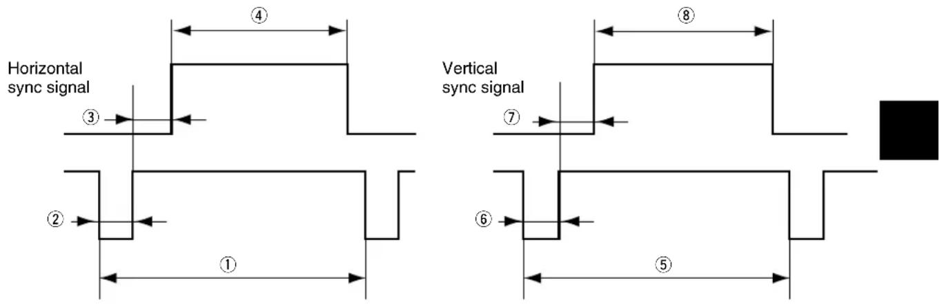
| Horizontal sync signal | 1 Cycle2 Sync signal width3 Back porch4 Display interval | 20.677 μs2.092 μs2.462 μs15.754 μs |
| Vertical sync signal | 5 Cycle6 Sync signal width7 Back porch8 Display interval | 806 H6 H29 H768 H |
| Scan mode | Non-interlaced | |
NOTE
- The screen is sometimes not displayed normally depending on the monitor or projector that is connected.
- Images from a PC are output in standby.
■ When Images on the Personal Computer Screen are not Projected
Check the following when images on the personal computer screen are not projected or projected images are incorrect.
● When images are not projected
When external output signals are input to the MP-50E from the PC, "No signal" is displayed on the screen. When this is displayed, check the following.
1 Try restarting the personal computer.
The MP-50E is sometimes not recognized by the PC if it is connected after the PC is started up. If this happens, images are not projected as external output signals are not output from the PC.
2 Check the functions on the personal computer.
Some notebook PCs require a special operation to transmit the signals from the external output terminal. The external output signals may not be transmitted from the notebook PC unless the operation is performed. Refer to the manuals of your notebook PC for the information about how to output signals from the external output terminal.
Procedure example
• In the case of IBM PC/AT:
Press Fnkey together with one of the keys, F1-F12. This procedure may vary depending on the model.)
○ List of remedies when connection trouble with the PC occurs
| Manufacturer Series | External Output Switching Method | |
| IBM Think Pad Fn+f7 | ||
| COMPAQ CONTURA ARMADA | Fn+f4 | |
| LATITUDEDELL | Fn+f8 | |
* The above table summarizes conditions that have occurred to date; it is not a comprehensive summary of all connections.
* Company names and product names listed in the above table are trademarks or registered trademarks of respective companies.
● Images are not projected correctly even though they are displayed normally on the notebook PC screen
1 Verify the functions of the notebook PC.
Even if the LCD screen of a notebook PC displays normal images, the projected images may be displayed incorrectly. In most cases, because of the limitations of the notebook PC, the simultaneous display function (the external output signals are sent out simultaneously while the images are displayed on the PC screen) produces signals, which do not satisfy the standard specification and are outside the range supported by the projector. In this case, the incorrect display images can not be corrected even if the fine adjustments are made at the projector side. The correct images may be projected if only external output signals are provided without using the simultaneous display. Refer to the user's manual of your notebook PC for details.
■ Input Signal Compatibility Table (PC video input terminal)
The MP-50E supports the signals marked by ● in the following table. Note that on some PC models, flickering and blurring occur in the projected image. If this happens, adjust the projected image in the Sync Adjustment menu.
| Signal Name | Resolution(Horizontal X Vertical) (kHz) | Horizontal Frequency(Hz) | Vertical Frequency | Compatibility | |
| NTSC RGB - - 15.7 60 × | |||||
| PAL/SECAM RGB - - 15.6 50 × | |||||
| VGA-GR1 640 480 31.5 60 ● | |||||
| VGA-GR2* 640 400 31.5 70 ● | |||||
| VGA-GR3* 640 350 31.5 70 ● | |||||
| VGA-TX1* 720 400 31.5 70 ● | |||||
| VGA-TX2* 720 350 31.5 70 ● | |||||
| 640×480 72Hz | 640 | 480 | 37.8 | 72 | ● |
| 640×480 75Hz | 640 | 480 | 37.5 | 75 | ● |
| 640×480 85Hz | 640 | 480 | 43.2 | 85 | ● |
| Mac13"RGB | 640 480 35.0 66 ● | ||||
| 800×600 56Hz | 800 | 600 | 35.1 | 56 | ● |
| 800×600 60Hz | 800 | 600 | 37.8 | 60 | ● |
| 800×600 72Hz | 800 | 600 | 48.0 | 72 | ● |
| 800×600 75Hz | 800 | 600 | 46.8 | 75 | ● |
| Mac16"RGB | 832 624 49.7 74 ● | ||||
| 1024×768 43Hz | 1024 | 768 | 35.5 | 43 | × |
| 1024×768 60Hz | 1024 | 768 | 48.3 | 60 | ● |
| 1024×768 70Hz | 1024 | 768 | 56.4 | 70 | ● |
| 1024×768 75Hz | 1024 | 768 | 60.0 | 75 | ● |
| 1024×768 85Hz | 1024 | 768 | 68.7 | 85 | ● |
| MAC19"1024×768 | 1024 | 768 | 60.2 | 75 | ● |
| MAC21"1152×864 | 1152 | 864 | 68.7 | 75 | ● |
| 1280×960 60Hz | 1280 | 960 | 60.0 | 60 | ● |
| 1280×960 85Hz | 1280 | 960 | 85.9 | 85 | ● |
| 1280×1024 60Hz | 1280 | 1024 | 64.0 | 60 | ● |
| 1280×1024 75Hz | 1280 | 1024 | 80.0 | 75 | ● |
| 1280×1024 85Hz | 1280 | 1024 | 91.1 | 85 | ● |
| 1600×1200 60Hz | 1600 | 1200 | 75.0 | 60 | ● |
| 1600×1200 65Hz | 1600 | 1200 | 81.3 | 65 | × |
| 1600×1200 70Hz | 1600 | 1200 | 87.5 | 70 | × |
| 1600×1200 75Hz | 1600 | 1200 | 93.8 | 75 | × |
| 1600×1200 85Hz | 1600 | 1200 | 106.3 | 85 | × |
- When the input signal resolution is lower than 1024 × 768 dots, enlarge the display. When it is higher, compress the display.
- Signals marked with an * may become fuzzy if too much vertical keystone compensation is applied. When using one of these signals, set the keystone compensation so that it does not distort the image.
● Basic connections

flowchart
graph TD
    A["To speaker input terminals"] --> B["To speaker input fasteners"]
    B --> C["Terminal panel on the back of the MP-50E main unit"]
    C --> D["To audio output terminal on PC"]
    D --> E["To analog RGB connector on monitor"]
    E --> F["To RGB output connector on PC"]
    F --> G["The connector cable model No. differs according to the type of PC"]
NOTE
- The personal computer has input terminals for both image and sound for "1" and "2". Hook up the sound and image to the corresponding terminals. If they are not hooked up to the corresponding terminals, the image and sound will not be output correctly.
• See page E-11 for information about the input and output terminals.
● Connecting to IBM NOTE and Compatible

NOTE
After you have connected the supplied cable, check the external CRT output/internal LCD output states and set the mode in the software running on the PC.
The connection with the PC will not be made if you do not set the external CRT output mode.
● Connecting to an IBM Desktop and Compatible

NOTE
When connecting the projector directly to the PC without using the monitor supplied with the PC, you can connect by the supplied cable only.
● Connecting to Apple Macintosh Notebook
Excluding Power Book Duo, 100, 140, 145B, 150, 170

NOTE
- When connecting the Power Book Duo, the Duo Dock or Mini Dock is required.
- The Power Book display adapter is sometimes not supplied with the Power Book. If it is not supplied, buy a separate display adapter from a Macintosh computer store. (Apple M3927LL/A or equivalent)
■ Connecting to a Video Source or DVD Player
Images from a video source or DVD player can be projected on a large screen.

NOTE
- When both VIDEO and S-VIDEO are connected, S-VIDEO is given higher display priority.
- Before using the video source or DVD player, close the materials cover. (Otherwise, the glass on the scanner may vibrate and cause a rattling sound.)
■ Preparation

1 Connect the power cord.

The projector is in the standby mode, and the power indicator LED lights (red).

Press the POWER button. The fan spins, the LED lights, and the ON/STANDBY LED lights (green).
The LAMP/COVER LED lights (green).
If the LAMP/COVER LED lights red after turning on the POWER button, then there is something wrong. (See page E-52 for details.)
NOTE
Make sure that the lens cap has been removed before turning on the power.
2 Select the external input device.

Select the video source to be displayed from OHP, PC1/PC2, or VIDEO.

flowchart
graph TD
    A["The selected input display is displayed."] --> B["OHP"]
    A --> C["PC/video"]
    B --> D["See page E-30."]
    C --> E["See page E-37."]
Remote Control Operation

NOTE
When PC/VIDEO is selected and the device is not connected, or the connected device is not turned on, "No input" is displayed.
■ Basic Operations in the OHP Mode
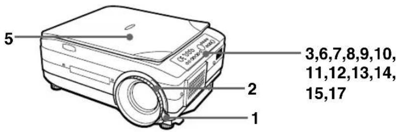
NOTE
The projected image in the OHP display (projection of actual object) may be slightly distorted as a very wide-angle lens is used.
1 Adjust the size of the projected image.
natural_image
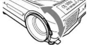
Technical line drawing of a projector with a circular housing and a screen (no text or symbols)Rotate the zoom adjuster on the projection lens to adjust the size of the projected image.
2 Adjust the focus.

Adjust the focus adjuster on the projection lens until the projected image is sharp.
3 Compensate the keystone. (Main Unit Operation)
KEYSTONE

Remote Control Operation
KEYSTONE

See "Compensating Keystone" on page E-21.
4 Check the OHP's initial screen.
When you select OHP, the "Set your document and press the REFRESH button" message appears and the projected image becomes all white, and a window that shows how the document is moving appears on the bottom right of the projected image.
5
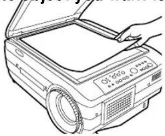
Set the object you want to project.
natural_image
Line drawing of a projector with open lid and handle, no text or symbols presentOpen the materials cover, and place the document or printed matter you want to project on the scanner.
A video image of the projected material appears in the window.

Close the materials cover.
NOTE
Objects can be projected even if the materials cover is not closed. However, unwanted objects will also be picked up, making the projected image difficult to view.
6
Adjust the brightness. (Main Unit Operation)

Remote Control Operation

Pressing the □ button (or the □ button on the remote controller) darkens the projected image, and pressing the □ button (or the □ button on the remote controller) lightens the projected image.
The “Brightness” value on the “Image Adjustment” menus changes in accordance with the brightness adjustment. See page E-43 for more information.
NOTE
When projecting dark documents or printed matter, adjust to lighten the projected image, and when projecting bright documents or printed matter, adjust to darken the projected image.
7
Switch the orientation of the projected image.
Main Unit Operation

Orient the image in the direction of the document.
Press the POSITION button to switch the orientation of the projected image.
ROTATION button: Flip the projected image top to bottom.
V ↔ H button: Switch the image from a vertical to a horizontal display.
Remote Control Operation
8

9
10

11
12
(Main Unit Operation)

RESIZE

Remote Control Operation
RESIZE

Project a full-screen image.
When projecting a vertical image, press the RESIZE button to switch between a projected image that fills the screen from side to side or to one that fills the screen from top to bottom. (You can switch them even when adjusting the zoom.)
13
Main Unit Operation

LIVE IMAGE
IMAGE

Remote Control Operation
LIVE IMAGE

Make the projected image live.
There are the two following methods to move the document while checking the projected image.
①Make the window live.
Set "Window" in "Movie mode" in the quick menu (page E-51). Pressing the LIVE IMAGE button displays live images in the window on the bottom right of the image.
②Make the entire image live.
Set "Full" in "Movie mode" in the quick menu (page E-51). Pressing the LIVE IMAGE button displays live images on the entire projected image at about 1 frame per second. In this setting, the image doesn't change even if you press the LIVE button.
14
Main Unit Operation

IMAGE


VOLUME
Remote Control Operation
OHP STORED IMAGE


View OHP STORED IMAGE.
When you press the REFRESH button and the image freezes, a maximum of eight pages of the OHP images are stored on the internal MP-50E memory.
Press the OHP STORED IMAGE button to view and change the stored images on the internal memory. See page E-40 for details.
◀ button: Display the image previous to the currently displayed image from stored image.
▶ button: Display the image following the currently displayed image from stored image.
You can switch the stored images from the quick menu (page E-51) when viewing the OHP stored image.
NOTE
- Pressing the POWER button and going into standby erases the OHP stored images.
- The brightness can not be adjusted when viewing OHP stored image. Adjust the brightness before pressing the REFRESH/FREEZE button.
15
Main Unit Operation


POINTER
Remote Control Operation

NOTE
Adjusting the zoom or the brightness while the pointer is displayed may cause it to disappear momentarily, but it will reappear after a short time.
Display the pointer.
Press the SET/POINTER button to display the pointer. Press it again to hide the pointer.
Press the SCROLL button to move the pointer.
16
Remote Control Operation
POINTER TYPE

Select the type of pointer.
You can switch the type of pointer with the POINTER TYPE button on the remote controller. (Select from ↗, ● or .) + You can also select the type from "Pointer type" on the "Setting 2" menu. See page E-45 for details.
17
Main Unit Operation


Remote Control Operation
MUTE

Mute the image.
Press the MUTE button to stop projecting the image without turning off the lamp. You can select the image projected while the image is muted from the following two images.
①Project a completely black image while the projected image is muted.
Set "Black" in "Mute mode" on the "Setting 2" menu (page E-45). While the image is muted, the projecting black image ☒ icon is displayed on the top right side of the projected image.
②Project an arbitrary image while the projected image is muted.
Set "logo" in "Mute mode" on the "Setting 2" menu (page E-45).
While the image is muted, the projecting image 📁 icon is displayed on the top right side of the screen.
NOTE
After the projected image has been muted for a certain amount of time (about 15 minutes) it automatically goes into standby.
Document Orientation and Scan Size
Place the document or printed matter face down at the orientation shown in the figure below.
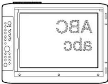
The maximum size that documents or printed matter can be scanned is 216 mm/8.5 in (vertical) and 288 mm/11.3 in (horizontal). For this reason, the projected sizes are as follows when an A4-size sheet of paper is placed at the respective orientations. (Shaded section is the projected area.)

Parts protruding outside the scan area are not projected on the screen. To project these parts, move the paper.
Displaying Live image in the window
While it is possible to display Live images in the window, the Live image is low resolution and is displayed against a background of a high definition frozen image on the main part of the projected image.
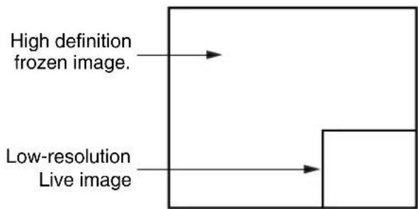
flowchart
graph TD
    A["High definition frozen image."] --> B["Low-resolution Live image"]
When the window is displayed, the "BRIGHTNESS," "V ↔ H," and "ROTATION" buttons are enabled for the window, but the ZOOM buttons are enabled for the main part of the projected image. (When you press the ZOOM buttons, the window disappears momentarily, but is displayed again after a short time.
Displaying OHP stored image
Pressing the 📄D buttons display and switch the stored images in the internal memory. button: Displays the image previous to the stored image that is currently displayed. button: Displays the image following the stored image that is currently displayed. * Pressing the 📄D button while a stored image is not displayed causes the most recently refreshed image that was stored to be displayed.
When you press the REFRESH button and the image freezes, a maximum of eight pages of the OHP images are stored on the internal MP-50E memory.
Press the POWER button, then after selecting OHP mode, the image of the first frozen image is stored to position ① in the diagram below. After that, every time you refresh the display the images are stored in the internal memory. When the stored images exceed the maximum of eight images the oldest images are overwritten in the order shown in the diagram below (starting from ①).

flowchart
graph TD
    ①[①] -->|VOLUME| ②[②]
    ② -->|VOLUME| ③[③]
    ③ -->|VOLUME| ④[④]
    ④ -->|VOLUME| ⑤[⑤]
    ⑤ -->|VOLUME| ⑥[⑥]
    ⑥ -->|VOLUME| ⑦[⑦]
    ⑦ -->|VOLUME| ⑧[⑧]
    ⑧ -->|VOLUME| ①
    ② -->|OPH STORED MAGE| ①
    ③ -->|OPH STORED MAGE| ②
    ④ -->|OPH STORED MAGE| ③
    ⑤ -->|OPH STORED MAGE| ⑥
    ⑥ -->|OPH STORED MAGE| ⑦
    ⑦ -->|OPH STORED MAGE| ⑧
    ① -->|OPH STORED MAGE| ①
    ② -->|OPH STORED MAGE| ②
    ③ -->|OPH STORED MAGE| ③
    ④ -->|OPH STORED MAGE| ④
    ⑤ -->|OPH STORED MAGE| ⑥
    ⑥ -->|OPH STORED MAGE| ⑦
■ Basic Operation of PC or Video Input

1 Adjust the size of the projected image.

natural_image
Diagram of a projector with a circular component and arrow indicating direction (no text or symbols)Rotate the zoom adjuster on the projection lens to adjust the size of the projected image.
2 Adjust the focus.

Adjust the focus adjuster on the projection lens until the projected image is sharp.
3 Compensate keystone. (Main Unit Operation)
KEYSTONE

Remote Control Operation
KEYSTONE

See "Compensating Keystone" on page E-21.
4 Adjust the brightness. Main Unit Operation


Remote Control Operation
Pressing the □ button (or the □ button on the remote controller) darkens the projected image, and pressing the □ button (or the □ button on the remote controller) lightens the projected image.
The “Brightness” value on the “Image Adjustment” menus changes in accordance with the brightness adjustment. See page E-47 for more information.
5
Adjust the zoom ratio. Main Unit Operation

Remote Control Operation

You can adjust the zoom between 1x to 4x.
Pressing the button (or the button on the remote controller) reduces the image, and pressing the button (or the button on the remote controller) enlarges the image.
6
Move the zooming position. (Main Unit Operation)
SCROLL

Remote Control Operation
Press the arrow buttons on the remote controller to move the zooming position of the image. You can move in eight directions. (Up, down, left, right and diagonally).
7
Synchronized Adjustments (Main Unit Operation)
[Non-Text]
RESIZE

Remote Control Operation
RESIZE

Press the RESIZE button to do automatic synchronous adjustments of each setting to the most suitable status on the "Sync Adjust" menu (Page E-44).
8
Display the pointer. Main Unit Operation
SET

POINTER
Remote Control Operation
NOTE
Press the SET/POINTER button to display the pointer. Press it again to hide the pointer.
Press the SCROLL button to move the pointer.
Adjusting the zoom or the brightness while the pointer is displayed may cause it to disappear momentarily, but it will reappear after a short time.
9


You can switch the type of pointer with the POINTER TYPE button on the remote controller. (Select from ↗, ● or .) + You can also select the type from "Pointer type" on the "Setting 2" menu. See page E-45 for details.
10
Main Unit Operation

Adjust the volume.
Press the button to reduce the volume. Press the button to increase the volume.
Remote Control Operation

11
Main Unit Operation

Freeze the projected image.
Press the FREEZE button to freeze the image from the personal computer or video. To unfreeze the image, press the FREEZE button again, or press the LIVE button.
Remote Control Operation

NOTE
- You can not adjust the brightness when the image is frozen. Adjust the brightness before pressing the FREEZE button.
- Press the INPUT SELECT button to unfreeze the image when it is frozen.
12
Remote Control Operation

Display images from the personal computer and the video at the same time.
If you select personal computer input while a video source and a personal computer are both connected, you can display video images in the window at the lower right side of the projected image. Set “Picture in Picture” to “ON” on the quick menu to display video images. See page E-51 for details.
NOTE
- The P in P button is only enabled when a personal computer is selected. You can not use it when video is selected.
- You can not use the picture in picture function if the signal from the personal computer is not being input.
13
Main Unit Operation
MUTE

Remote Control Operation
MUTE

Mute the image.
Press the MUTE button to stop projecting the image without turning off the lamp. You can select the image projected while the image is muted from the following two images.
①Project a completely black image while the projected image is muted.
Set "Black" in "Mute mode" on the "Setting 2" menu (page E-45). While the image is muted, the projecting black image
☒ icon is displayed on the top right side of the projected image.
②Project an arbitrary image while the projected image is muted.
Set "logo" in "Mute mode" on the "Setting 2" menu (page E-45).
While the image is muted, the projecting image 📁 icon is displayed on the top right side of the projected image.
NOTE
After the projected image has been muted for a certain amount of time (about 15 minutes) it automatically goes into standby.
■ How to Quit

1
Main the lamp operation
POWER

Remote Control Operation
POWER
Press the POWER button. (Hold down for at least one second.)

"Press POWER button again to turn off." is displayed on the projected image.

Press the POWER button again.
The LAMP/COVER LED blinks green, and then goes out after about one minute.
The ON/STANDBY LED lights (red.)
NOTE
The lamp will not turn on even if you press the POWER button if the LAMP/COVER LED is blinking green. To turn the lamp on again, press the POWER button again after the ON/STANDBY LED lights red.
2
Disconnect the power cord.

The ON/STANDBY LED on the operation panel goes out.

CAUTION
- Do not disconnect the power cord before the lamp goes off or the LAMP/COVER LED lights. Doing so may shorten the life of the lamp.
- Disconnect the power cord from the power outlet if you are not going to use the projector for a long period of time.
• After disconnecting the power cord from the power outlet, wait a certain period of time (about 10 seconds) before connecting it again.
■ Performing Various Adjustments
Menu Structure
You can perform various adjustments and make various settings by operating the buttons with the menu display displayed on the projected image.
There are two menus, the "Quick menu" on which there are frequently used items, and the "Main menu" on which more detailed settings can be done.
When a personal computer or video is connected and the power is on, you can open the "Quick menu" by pressing the ○ button (or the ⊙ button on the remote controller.) (See Page E-51 for information about the Quick menu.)
Press the ⏻ button (or the ⏻ button on the remote controller) again and the Main menu opens. You can go to the Adjust Settings menu from the Main menu display. A map of the menu displays is shown below.
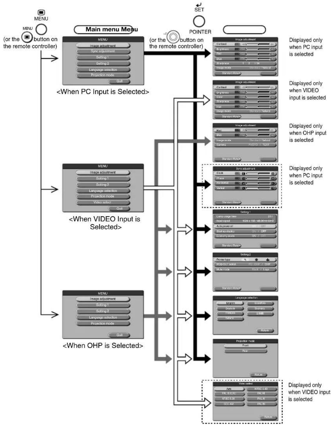
flowchart
graph TD
    A["MENU (or the button on the remote controller)"] --> B["Menu"]
    B --> C["Main menu Menu"]
    C --> D["SET"]
    D --> E["Pointer"]
    E --> F["Main output"]
    F --> G["PC input selected"]
    G --> H["Display only when PC input is selected"]
    C --> I["Main output"]
    I --> J["Main output selected"]
    J --> K["PC input selected"]
    K --> L["Display only when OHP input is selected"]
    C --> M["Main output"]
    M --> N["Main output selected"]
    N --> O["PC input selected"]
    O --> P["Display only when OHP input is selected"]
    C --> Q["Main output"]
    Q --> R["Main output selected"]
    R --> S["PC input selected"]
    S --> T["Display only when OHP input is selected"]
Description of Menu Items
The following describes each of the menu displays, and the items and functions that can be set in these menu displays. For details of how to set these menu items, see “Basic Operation” on page E-47.
◆ Image Adjustment (when PC input is selected)

| Menu Item | Setting Item | Description |
| Contrast | -100 ~ +100 | Adjusts the contrast of the projected image. |
| Brightness | -100 ~ +100 | Adjusts the brightness of the projected image. |
| Red | -100 ~ +100 | Adjusts the depth of the color red. |
| Blue | -100 ~ +100 | Adjusts the depth of the color blue. |
| Sharpness* | 1 ~ 5 | Adjusts image sharpness. The higher the number goes the more clear the image becomes. The standard is “3.” |
| Image mode | Standard/Natural | If you want to display an image that has high contrast and sharpness select “Standard”; if you want to reproduce colors that are close to the original select “Natural.” |
* Sharpness is especially effective when the images are enlarged and zoomed or if keystone compensation has been done.
◆ Image Adjustment (when VIDEO input is selected)

| Menu Item | Setting Item | Description |
| Contrast | -100 ~ +100 | Adjusts the contrast of the projected image. |
| Brightness | -100 ~ +100 | Adjusts the brightness of the projected image. |
| Color | -100 ~ +100 | Adjusts the color of projected images. |
| Sharpness | 0 ~ 6 | Adjusts image sharpness. |
| Hue | -100 ~ +100 | Adjusts the hue of projected images. |
| Image mode | Standard/Natural | If you want to display an image that has high contrast and sharpness select “Standard”; if you want to reproduce colors that are close to the original select “Natural.” |
◆ Image Adjustment (when OHP is selected)

| Menu Item | Setting Item | Description |
| Red | -100 ~ +100 | Adjusts the depth of the color red. |
| Blue | -100 ~ +100 | Adjusts the depth of the color blue. |
| Image mode | Standard/Natural | If you want to display an image that has high contrast and sharpness select “Standard”; if you want to reproduce colors that are close to the original select “Natural.” |
| Gamma | PHOTO/TEXT | The TEXT setting compensates for text documents, and the PHOTO setting compensates for photo documents.Select the setting to suit the document you are projecting. |
◆ Sync Adjustment (only when PC input is selected)

| Menu Item | Setting Item | Description |
| Clock | -100 ~ +100 | Adjusts the horizontal size of the image. |
| Phase | -100 ~ +100 | Adjusts noise and flickering. |
| Horizontal | -100 ~ +100 | Adjusts the horizontal position of the image. |
| Vertical | -100 ~ +100 | Adjusts the vertical position of the image. |
NOTE
Menu items sometimes cannot be adjusted within the range -100 to +100 depending on the PC input signal.
Setting 1

| Menu Item | Setting Item | Description |
| Auto power off | ON/OFF | Sets the auto power off function ON/OFF. When auto power off is set to ON, the projector automatically goes to standby mode if no signals are input for a fixed period of time (about 15 minutes). |
| Start-up display | ON/OFF | Sets whether or not to display the Logo while the lamp is on. |
| Economy mode | ON/OFF | Sets the lamp in Economy mode. |
NOTE
In the "Setting 1" menu, the currently set input signals and lamp usage time can be displayed for confirmation.
Setting 2
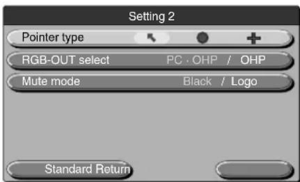
| Menu Item | Setting Item | Description |
| Pointer type | +/●/+ | Selects a type of pointer from among the three types. |
| RGB-OUT select | PC·OHP/OHP | When PC·OHP is selected:If the input selection is OHP, then the image is output as an OHP image for which the timing is changed to (XGA 60Hz) on page E-23.If the input selection is personal computer/video, then the personal computer image is a straight through output.When OHP is selected:No matter what input selection is made, OHP images are output at (XGA 60Hz) timing on page E-24. |
| Mute mode | Black/Logo | Sets the image to be displayed when the projected image is muted.When black is selected:The entire projected image appears black.When Logo is selected:Logo is displayed. |
◆ Language Selection

(Language Selection Menu>
| Menu Item | Setting Item | Description |
| Language selection | English | Sets the language used in display. |
| Deutsch | ||
| Français | ||
| Italiano | ||
| Española | ||
| Svenska | ||
| 日本語 |
◆ Projection Mode
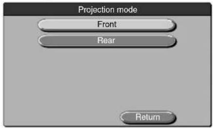
| Menu Item | Setting Item | Description |
| Projection mode | Front | Adjusts the projection mode according to the installation method (front (standard) projection or rear projection). |
| Rear |
◆ Video Select (only when video source input is selected)


- Multi-Function LCD Projector MP-50E
- User's Manual
- ● Features
- ● About Trademarks
- Warnings and Safety Precautions
- ● Warning Symbols
- ● Safety Precautions
- WARNING
- CAUTION
- • Care of the projector
- - Avoid scratching the glass surface.
- - Batteries
- • Servicing and cleaning
- - If not using the projector for a long period:
- - Disposal
- - Transporting the projector
- - Lamp implosion
- Note the following things
- Remedy
- - Replacing the lamp
- - Replacing / cleaning the air filter
- - Avoiding malfunctions and accidents
- - Do not disassemble the manganese batteries
- - Do not do the followings
- - Moving the projector
- - Care of the power cord and plug
- - DO NOT REMOVE ANY SCREWS except the lamp cover screw and two lamp unit screws. You could receive an electric shock.
- What's in the Box?
- Contents
- Part Names and Functions....E-9
- How to Install the Projector .... E-18
- Connecting to a Personal Computer ...... E-22
- Basic Operation E-29
- Maintenance E-52
- Troubleshooting ...... E-57
- Repair Service.... E-58
- Specifications ...... E-59
- Part Names and Functions
- Projector
- Handle
- NOTE
- About the anti-theft lock
- Lamp Unit Cover
- (bottom of main unit)
- ■ Terminal Panel
- ■ Buttons and Indicator Lights
- Remote Controller
- ■ Remote Control Operations
- ■ Battery Replacement
- How to Install the Projector
- ■ Installation Sequence
- ■ Adjusting the Tilt
- ■ Projection Distance and Projected Image Size
- Installation location
- ■ Typical Installation
- Select the installation site
- ■ Compensating Keystone
- ● How to Compensate Keystone
- Connecting to a Personal Computer
- Cautions on Connection
- ■ Connecting to a Personal Computer
- ● List of cables and adapters
- About the PC Input and Output
- ■ About RGB Video Output
- ● Signal timing
- ■ When Images on the Personal Computer Screen are not Projected
- ● When images are not projected
- Try restarting the personal computer.
- Check the functions on the personal computer.
- ● Images are not projected correctly even though they are displayed normally on the notebook PC screen
- Verify the functions of the notebook PC.
- ■ Input Signal Compatibility Table (PC video input terminal)
- ● Basic connections
- ● Connecting to IBM NOTE and Compatible
- ● Connecting to an IBM Desktop and Compatible
- ● Connecting to Apple Macintosh Notebook
- ■ Connecting to a Video Source or DVD Player
- ■ Preparation
- Connect the power cord.
- Select the external input device.
- Remote Control Operation
- ■ Basic Operations in the OHP Mode
- Adjust the size of the projected image.
- Adjust the focus.
- Compensate the keystone. (Main Unit Operation)
- Check the OHP's initial screen.
- 5
- Set the object you want to project.
- 6
- Adjust the brightness. (Main Unit Operation)
- 7
- Switch the orientation of the projected image.
- Main Unit Operation
- 8
- 9
- 10
- 11
- 12
- (Main Unit Operation)
- Project a full-screen image.
- 13
- Make the projected image live.
- 14
- View OHP STORED IMAGE.
- 15
- Display the pointer.
- 16
- Select the type of pointer.
- 17
- Mute the image.
- Document Orientation and Scan Size
- Displaying Live image in the window
- Displaying OHP stored image
- ■ Basic Operation of PC or Video Input
- Compensate keystone. (Main Unit Operation)
- Adjust the brightness. Main Unit Operation
- Adjust the zoom ratio. Main Unit Operation
- Move the zooming position. (Main Unit Operation)
- Synchronized Adjustments (Main Unit Operation)
- Display the pointer. Main Unit Operation
- Adjust the volume.
- Freeze the projected image.
- Display images from the personal computer and the video at the same time.
- ■ How to Quit
- 1
- Main the lamp operation
- 2
- Disconnect the power cord.
- ■ Performing Various Adjustments
- Menu Structure
- Description of Menu Items
- ◆ Image Adjustment (when PC input is selected)
- ◆ Image Adjustment (when VIDEO input is selected)
- ◆ Image Adjustment (when OHP is selected)
- ◆ Sync Adjustment (only when PC input is selected)
- Setting 1
- Setting 2
- ◆ Language Selection
- ◆ Projection Mode
- ◆ Video Select (only when video source input is selected)
- Basic Operation
- 3
- Press the 📄 button (or the Ⓞ button on the remote controller).
- When selecting "ON" or "OFF".
- 4-1
- Press the △/▽ buttons to select the item you want to set.
- 4-2 Press the buttons to select "ON" or "OFF".
- When adjusting in single point units
- 4-1 Press the buttons to select the item you want to set.
- 4-2 Press the buttons to adjust the setting.
- Others
- 4-1 Press the △/▽ buttons to select the item you want to set.
- Press the buttons to select "Quit" and then press the button (or ◎ button on the remote controller).
- ■ Quick Menu
- ◆ When OHP Is Selected
- ◆ When the OHP stored image Is Displayed
- ◆ When PC Input Is Selected
- ◆ When VIDEO Input Is Selected
- ■ Fault Protection
- ● When the LAMP/COVER LED is blinking:
- ○ Action
- ● When the temperature LED is blinking or on.
- ■ Lamp Unit Replacement
- Lamp usage 1400 hours. Replace the lamp.
- Procedure
- Remove the lamp unit cover.
- ■ Cleaning the Air Filter
- Remove the air filter.
- Vacuum the sponge to take off dust.
- Mount the air filter.
- Caring for the Air Filter and Cautions
- Repair Service
- Repair Service Procedure
- Specifications
Brand : Elmo
Model : MP-50E
Category : Projector