
CCT985W - Basket CANDY - Free user manual and instructions
Find the device manual for free CCT985W CANDY in PDF.



| Product Type | Kitchen hood |
| Brand | CANDY |
| Model | CCT985W |
| Width | 90 cm |
| Usage modes | External evacuation or recirculation (charcoal filter) |
| Number of speeds | 3 speeds + Clean Air function |
| Lighting | Integrated lighting (control keys) |
| Timer | Automatic shutdown after 15 minutes |
| Grease filters | Dishwasher safe (every 2 months) |
| Charcoal filter | Replaceable (included) |
| Minimum safety distance | 65 cm between hood and cooking surface |
| Power supply | 220-240 V, 50-60 Hz |
| Protection class | Class II (double insulation) |
| Control type | Electronic (keys) or mechanical (depending on version) |
| Filter saturation indicator | Yes (flashing of key A) |
| Memory reset | Press and hold key A for 5 seconds after cleaning |
| Exterior maintenance | Cloth moistened with denatured alcohol or neutral detergent |
| Lamps (depending on model) | Halogen or incandescent (replaceable) |
| Serial number | 16 characters starting with 3 (on internal plate) |
Frequently Asked Questions - CCT985W CANDY
User questions about CCT985W CANDY
0 question about this device. Answer the ones you know or ask your own.
Ask a new question about this device
Download the instructions for your Basket in PDF format for free! Find your manual CCT985W - CANDY and take your electronic device back in hand. On this page are published all the documents necessary for the use of your device. CCT985W by CANDY.
USER MANUAL CCT985W CANDY
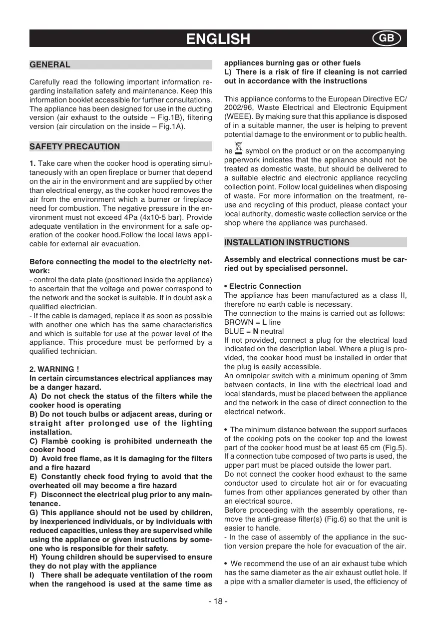
Carefully read the following important information regarding installation safety and maintenance. Keep this information booklet accessible for further consultations. The appliance has been designed for use in the ducting version (air exhaust to the outside - Fig.1B), filtering version (air circulation on the inside - Fig.1A).
SAFETY PRECAUTION
- Take care when the cooker hood is operating simultaneously with an open fireplace or burner that depend on the air in the environment and are supplied by other than electrical energy, as the cooker hood removes the air from the environment which a burner or fireplace need for combustion. The negative pressure in the environment must not exceed 4Pa (4x10⁻⁵ bar). Provide adequate ventilation in the environment for a safe operation of the cooker hood. Follow the local laws applicable for external air evacuation.
Before connecting the model to the electricity network:
- control the data plate (positioned inside the appliance) to ascertain that the voltage and power correspond to the network and the socket is suitable. If in doubt ask a qualified electrician.
- If the cable is damaged, replace it as soon as possible with another one which has the same characteristics and which is suitable for use at the power level of the appliance. This procedure must be performed by a qualified technician.
2. WARNING!
In certain circumstances electrical appliances may be a danger hazard.
A) Do not check the status of the filters while the cooker hood is operating
B) Do not touch bulbs or adjacent areas, during or straight after prolonged use of the lighting installation.
C) Flambé cooking is prohibited underneath the cooker hood
D) Avoid free flame, as it is damaging for the filters and a fire hazard
E) Constantly check food frying to avoid that the overheated oil may become a fire hazard
F) Disconnect the electrical plug prior to any maintenance.
G) This appliance should not be used by children, by inexperienced individuals, or by individuals with reduced capacities, unless they are supervised while using the appliance or given instructions by someone who is responsible for their safety.
H) Young children should be supervised to ensure they do not play with the appliance
I) There shall be adequate ventilation of the room when the rangehood is used at the same time as
appliances burning gas or other fuels
L) There is a risk of fire if cleaning is not carried out in accordance with the instructions
This appliance conforms to the European Directive EC/ 2002/96, Waste Electrical and Electronic Equipment (WEEE). By making sure that this appliance is disposed of in a suitable manner, the user is helping to prevent potential damage to the environment or to public health.
he symbol on the product or on the accompanying paperwork indicates that the appliance should not be treated as domestic waste, but should be delivered to a suitable electric and electronic appliance recycling collection point. Follow local guidelines when disposing of waste. For more information on the treatment, reuse and recycling of this product, please contact your local authority, domestic waste collection service or the shop where the appliance was purchased.
INSTALLATION INSTRUCTIONS
Assembly and electrical connections must be carried out by specialised personnel.
Electric Connection
The appliance has been manufactured as a class II, therefore no earth cable is necessary.
The connection to the mains is carried out as follows: BROWN = L line
BLUE = N neutral
If not provided, connect a plug for the electrical load indicated on the description label. Where a plug is provided, the cooker hood must be installed in order that the plug is easily accessible.
An omnipolar switch with a minimum opening of 3mm between contacts, in line with the electrical load and local standards, must be placed between the appliance and the network in the case of direct connection to the electrical network.
- The minimum distance between the support surfaces of the cooking pots on the cooker top and the lowest part of the cooker hood must be at least 65~cm (Fig.5). If a connection tube composed of two parts is used, the upper part must be placed outside the lower part.
Do not connect the cooker hood exhaust to the same conductor used to circulate hot air or for evacuating fumes from other appliances generated by other than an electrical source.
Before proceeding with the assembly operations, remove the anti-grease filter(s) (Fig.6) so that the unit is easier to handle. - In the case of assembly of the appliance in the suction version prepare the hole for evacuation of the air.
- We recommend the use of an air exhaust tube which has the same diameter as the air exhaust outlet hole. If a pipe with a smaller diameter is used, the efficiency of
the product may be reduced and its operation may become noisier.
FIXING TO THE WALL
Drill the holes A respecting the distances indicated (Fig.2). Fix the appliance to the wall and align it in horizontal position to the wall units. When the appliance has been adjusted, definitely fix the hood using the screws A (Fig.4). For the various installations use screws and screw anchors suited to the type of wall (e.g. reinforced concrete, plasterboard, etc.). If the screws and screw anchors are provided with the product, check that they are suitable for the type of wall on which the hood is to be fixed.
- FIXING THE DECORATIVE TELESCOPIC FLUE - EXTRACTOR VERSION
Arrange the electrical power supply within the dimensions of the decorative flue. If your appliance must be installed as an extractor version, make sure an air exhaust hole has been prepared. Adjust the width of the support bracket of the upper flue (Fig.3). Then fix it to the ceiling using the screws A (Fig.3) in such a way that it is in line with your hood and respecting the distance from the ceiling indicated in Fig.2. Connect the flange C to the air exhaust hole using a connection pipe (Fig.4). Insert the upper flue into the lower flue and rest above the frame. Extract the upper flue up to the bracket and fix it with the screws B (Fig.3). Remove the charcoal filters already fitted to the appliance by turning them 90^ anticlockwise (Fig. 7).
- FILTERING VERSION
Install the hood and the two flues as described in the paragraph for installation of the hood in ducting version.
The charcoal filters are already fitted to the appliance.
USE AND MAINTENANCE
- We recommend that the cooker hood is switched on before any food is cooked. We also recommend that the appliance is left running for 15 minutes after the food is cooked, in order to thoroughly eliminate all contaminated air.
The effective performance of the cooker hood depends on constant maintenance; the anti-grease filter and the active carbon filter both require special attention. - The anti-grease filter is used to trap any grease particles suspended in the air, therefore is subject to saturation (the time it takes for the filter to become saturated depends on the way in which the appliance is used).
- To prevent potential fire hazards, the anti-grease filters should be washed a minimum of every 2 months (it is possible to use the dishwasher for this task).
- After a few washes, the colour of the filters may change. This does not mean they have to be replaced. If the replacement and washing instructions are not followed, the anti-grease filters may present a fire hazard.
- The active carbon filters are used to purify the air which is released back into the room. The filters are
not washable or re-usable and must be replaced at least once every four months. The active carbon filter saturation level depends on the frequency with which the appliance is used, the type of cooking performed and the regularity with which the anti-grease filters are cleaned.
- Clean the cooker hood frequently, both inside and outside, using a cloth which has been dampened with denatured alcohol or neutral, non-abrasive liquid detergents.
-
The light on the cooker hood is designed for use during cooking and not for general room illumination. Extended use of the light reduces the average duration of the bulb.
-
COMMANDS: (Fig.8) LUMINOUS the key symbols are explained below:
A = LIGHT
B = OFF
C = SPEED I
D = SPEED II
E = SPEED III
F = AUTOMATIC STOP TIMER - 15 minutes
- By pressing key F for two seconds (with the hood switched off) the "clean air" function is activated. This function switches the appliance on for ten minutes every hour at the first speed. As soon as this function is activated the motor starts up at the first speed for ten minutes, During this time key F and key C must flash at the same time. After ten minutes the motor switches off and the LED of key F remains switched on with a fixed light until the motor starts up again at the first speed after fifty minutes and keys F and C start to flash again for ten minutes and so on. By pressing any key for the exclusion of the hood light the hood will return immediately to its normal functioning (e.g. if key D is pressed the "clean air" function is deactivated and the motor moves to the 2nd speed straight away. By pressing key B the function is deactivated).
- Active carbon/grease filter saturation:
-
When button A flashes at a frequency of 2 seconds, the grease filters must be cleaned.
-
When button A flashes at a frequency of 0.5 seconds, the carbon filters must be replaced.
After the clean filter has been replaced, the electronic memory must be reset by pressing button A for approximately 5 seconds, until the light on the button stops flashing.
- COMMANDS: (Fig.9) MECHANICAL the key symbols are explained below:
A = LIGHT
B = OFF
C = SPEED I
D = SPEED II
E = SPEED III
G = MOTOR WORKING indicator
- COMMANDS: (pic.10) SLIDER the key symbols are explained below:
A = Light switch
A1 = Off key
A2 = On key
C = Speed control
C1 = Off key
C2 = FIRST SPEED key
C3 = SECOND SPEED key
C4 = THIRD SPEED key
- Replacing halogen light bulbs (Fig. 11).
To replace the halogen light bulbs B, remove the glass pane C using a lever action on the relevant cracks.
Replace the bulbs with new ones of the same type.
Caution: do not touch the light bulb with bare hands.
- Replacing incandescent light bulbs (Fig. 12).
To remove the incandescent light bulb, take out the grease filters as described in (Fig. 6) and remove the bulb.
Replace it with a new one of the same type (Fig. 12).
CUSTOMER ASSISTANCE SERVICE
Before contacting the Technical Assistance Service:
If the product does not operate at all, we advise you to: - check that the plug has been inserted into the power socket correctly.
If you cannot identify the cause of the operating anomaly: switch off the appliance (do not subject it to rough treatment) and contact the Assistance Service.
PRODUCT SERIAL NUMBER. Where can I find it?
It is important that you inform the Assistance Service of your product code and its serial number (a 16-character code which begins with the number 3); this can be found on the guarantee certificate or on the data plate located inside the appliance.
This will help to avoid wasted journeys being made by technicians, thereby (and most significantly) saving the corresponding callout charges.
THE MANUFACTURER DECLINES ALL RESPONSIBILITY FOR EVENTUAL DAMAGES CAUSED BY BREACHING THE ABOVE WARNINGS.
ALGEMEEN
INSTALLATIE INSTRUCTIES
POVELY: (Obr.8) Svetelne
BLA N Neutal
A = tast for BELYSNING
B = tast for OFF
C = tast for FØRSTE HASTIGHED
D = tast for ANDEN HASTIGHED
E = tast for TREDJE HASTIGHED
F = tast for TIMER AUTOMATISK STOP 15 minutter
YNHPEIA YNOSTHPHESNEATON
Piv kaéoet Tnv unpeia Te xviKic unootniipEnc.
A = tast for BELYSNING
B = tasting for OFF (AV)
C = tast for FØRSTE HASTIGHET
D = tasting for ANNEN HASTIGHET
E = tast for TREDJE HASTIGHET
F = tast TIDSURE AUTOMATISK STOPP 15 minutter
A = tast for BELYSNING
B = tast for OFF (AV)
C = tast for FØRSTE HASTIGHET
D = tast for ANNEN HASTIGHET
E = tast for TREDJE HASTIGHET
G = kontrollampe for MOTOR I FUNKSJON
KOMMANDOER: (Fig.10) SLIDER symbolenes betyd- ning:
A = Lysbryter
A1 = tast Off
A2 = tast On
C = Hastighetskontroll
C1 = tast Off
C2 = tast HASTIGHET EN
C3 = tasting HASTIGHET TO
C4 = tast HASTIGHT TRE
BLEUMARIN = N neutr u
H. He pa3pewaite Detam irpaTb c 3dJIeHem.
I. nepei IIO6Hm BvIDom TexyXoJa OTKJIIOuHTb BbITAAKKy O T3JEkTPOcETn
DaHHoe n3dJIne IMeET MapKIpOBky COOTBeTcBnE BEponeckomy HopMaTbY 2002/96/EC, YtIIN3aunr 3NeKTPUeCKHX n3NeKTPoHNbIX n3dJIEN (WEEE). PnpOBpe, YTOsbI no OKOHAnHero cPoka cnlyXbI daHHoe n3dJIe N6IbIo CdaHO bYTm. BbI nomOxete coxpaHntb OkpyXaOnyUcpeHy
CnMBOHHa n3dennnnnB npnaaraooceK Hemy DOKyMeHTaunn O3Haayet, YTO daHHoe n3dennne He dONJXHO paccMaTpNaBaTbca KAK 6bI TobIe OTXdbl, a DOxNHO 6bITc cAHO B CNEUaJIbHbIe UeHTp yTNIma3aunn, 3aHHMaIOuINc yHNUToxKeHNm ENeKTPruecknx n 3NeKTPOHbIX npnbOpOB. N3dennne DOJHXo 6bITc cAHO B yTNb B COOTBETCTBm C MeCTHbIMn HopMaTHbAMn NO yTNIma3auIN OTXdOB. 3a DOONHITeNBbIMn CBedeHnMI KacatEnbHO 6pb6OtKn, yTNIma3auIN n yHNUToxKeHNr DAHORO n3dennn O6paaNTecb B MecTHOE OTdelenne C6opbaOMaIHnx 6bITbIX npNbOpOB nIN B Mara3IN, B KOTOPM 6blNO kynHeNo n3dJeNn
INHCTPYKZIMI NOYCTAHOBKE
A=KHOIIKaOCBUEHnA
B=KNHONKa HnyeBoi
C = KhoNka nepBoNCKOPOCTN
D = KHOIIKA BTOPOI CKOPOCTN
E = KhoNka TpeTei CKoPoCTn
F = KHONKa TaMepa aBTOMaTnueCKoN OCTaHOBKn Yepe3 15 MmH
Haxatom noLOXeHNB TeueHne 2-xceKHydKnabuWy F.ДЯвькIoUOHeHnyФуHKuIIN "clean air" HaxaTb n depKataB T aKoTOM noLOxOeHNn KlaBnUwY F.3TaФуHKuIIN exeJaucho BKlIOUaet DbrarTeNb Ha nepBoN cKopoocTn Ha 10 MInHT, B TeueHne KOTOpbIX DoJNXbI MIRATb OndHOBPemEHHo yka3aTeNn KlaBnU W C. Nocne Yero DbrarTeNb BbIKIOUaETcra, a yka3aTeNb Ha KnabuWe F ocTaTc3 aXkxeHHbIM. Pnp6bn3nteNb Ho cepe3 50 MInHT ONrB BkIOUaETc DaBrarTeNb Ha nepBoi ckOPOCTn, yka3aTeNl F N ChauHaIOT MraTb B TeueHne 10 MInHT n.T.D.
HaxatneM IIO60I KNABNUbI, 3a NCKLIOUeHNEM KNABNUbI BKIOUeHnO CObSeHnA, DbIMOCOC Bo3BpauaETcB CBOE HOPMaNbHOe paOooey COCToHnE (HaNP., EcnI HAXATb KNABNUy D-OTKIOUaETcY fHKZn "clean air" IN DBrAtenb cpa3y Xe BKNIOuAeTcH Na 2° ckOpocTN; Haxab KNABNUy B fYNKznn OTKIOUaETcN).
3acopeneHne HnIbTpOB-JnnpoyNoBnteJe / HnIbTpcaKtNBnPoBAHHbIMyrEm:
-Korda muraet KhoNka A c qactoto2 cek., Heo6xoJIMMO BbIMbITb Hnbltpbl-JxnpoyNoBteJI.
-KorJa MmraET KhONka A C qactoto0 0,5 cek., Heo6xOIMO 3aMeHnTbΦJIbTpblc AKTNBPOBAHHbIM yrrnem.
Iocne yctaHOBKn Ha MeCTO YnCTORo 0nltpa HeoXoIMo O6HyNTb 3NeKtPOHHyNo nAMrTb, Haxab
KhONky A npimepno Ha 5 cek. BnIOTb do npekpaueHnMIRaHn.
Oprahby npabJeHnA: (Pnc.9) MexaHnueckne
A = KHOIIKa OCBeUeHnA
B=KNHONKa HnyeBOI
C = KHONKa nepBOI cKOPoCTN
D = KHONKA BTOPOI CKOPOCTN
E = KhoNka TpeTei CKoPoCTn
G=JaMnOuKa:ДВИГATEЛьВРАБОЧЕМPEXКIME
CINHAlbly UNPABLHeHn: (Puc.10) SLIDER
CIMBOLNka yKa3aHa HIXKe:
A = πepeKJIIOUaTeJIb CBeta
A1 = knaBnua Off
A2 = klaBnna On
C = peryIaTOp ckopoCTn
C1 = knaBnua Off
C2 = KlaBnua IEPBAI CKOPOCTb
C3 = KnaBnba BTOPOA CKOPOCTb
C4 = kλaνισα TPETbR CKOPOCTb
3aMeHa raIoreHHbIX lamn (Cxema 11).
Дязамени ГалoreньхлamпВсимITE cTeKЛанHHYO KpbIshkyC,poIdEe ee OTBepTKoB CpeMaJIbHbIx na3ax.
3aMeHInTe JAmNbI Ha JAmNbI TaKOrO Xe Tnna.
BhmuHHe: He npKacaiTecb K IaMnam roIbIMnyakuM.
- 3aMeHa JIaMn HakaJIbBaHn (Cxema 12).
Длзаимылампьндяраимпсдьгдьгдьгдьгдьгдьгдьгдьгдьгдьгдьгдьгдьгдьгдьгдьгдьгдьгдьгдьгдьгдьгдьгдьgннрбдьгннрбdьgннрбdьgннрбdьgннрбdьgннрбdьgннрбdьgннрбdьgннрбdьgннрбdьgннрбdьgннрбdьgннрбdьgннрбdьgннрбdьgннрбdьgнnрбdьgнnрбdьgнnрбdьgнnрбdьgнnрбdьgнnрбdьgнnрбdьgнnрбdьgнnрбdьgнnрбdьgнnрбdьgнnрбdьgнnрбdьgнnрбdьgнnр北尼ВуИЗБУМИЗВИЗМИЗВИЗМИЗВИЗМИЗВИЗМИЗВИЗМИЗВИЗМИЗВИЗМИЗВИЗМИЗВИЗМИЗВИЗМИЗВИЗМИЗВИЗМИЗВИЗМИЗВИЗМИЗВИЗМИЗВИЗМИЗВИЗМИЗBIVIZHIMINNININININININININININININININININININININININININININININININININININININININININININININININININININININININININININININININININININININININININININININININININININININININININININININININININININININ
3aMeHInTe IaMnOuKy Ha HOByIO TAKORO Je Tnna (Cxema 12).
CEPBNUCHOE OBCJYXKBAHNE IOKYNATEJEI
Ipeed tem kak o6paTntbC8 B LcHTp CepBnCHOrO O6cnyxmbAHna.
B cnyae HeucnpabHocTn BaWero n3denn pekomehyuem:
- npOBepntb, npOCHNO IIN BOTKHyTA wTeNCEJIbHaB BUNIka N3DeJIINB CcETeBYIO pO3ETKy.
Ecnn BbHe MoKTe O6HApXnTb npuHy HeCNpabNocTb: BbKlOChTe N3dEne, He nbTaanTecb packPbIT ero n o6paTntecb B LcHTp CepBnchOrO 06CnykmbAHn.
PACNOPTHAR TABJIYKA Ie OHa HaxoHTc?
Ipi6oebaHnBcHtp CepBncHOrO OcbnybAHnB BaxHo coo6uTb apTuKyn n Homep erO tex. IacnpTa (16-3naHbki KOD, NaHnHaOuSiNc C uNΦpb3), KOtopBle Bbl haJdtE B rapaHTnHOM TaIIOHe nIn Ha naCnpToHn TabnUKe, paCnoLoXeHHo BHyTpni N3dJIIN.
TakIM O6pa3OM MOXHO N36ExaTb HnpaCHORO Bbl3OBA TEXHnka, C3KOHOMNB Ha CTOnMOCTN ObCnyxNBAHNA.
ΦMNPHEHCETHNIKAKOITBETCTBEHHOCTN 3A UWEPB, BbI3BAHHHb HECO6JIIODEHNEM BbIJEENPNBIDEEHBHIX PNEUYPEXDEHN.
OBSERVERA
C = knapp FÖRSTA HASTIGHET
D = knapp ANDRA HASTIGHET
E = knapp TREDJE HASTIGHET
F = TIMER FÖR AUTOMATISK AVSTÄNGNING
EFTER 15 minute.
- SAFETY PRECAUTION
- Before connecting the model to the electricity network:
- WARNING!
- appliances burning gas or other fuels
- INSTALLATION INSTRUCTIONS
- Electric Connection
- FIXING TO THE WALL
- - FIXING THE DECORATIVE TELESCOPIC FLUE - EXTRACTOR VERSION
- - FILTERING VERSION
- USE AND MAINTENANCE
- - Active carbon/grease filter saturation:
- - Replacing halogen light bulbs (Fig. 11).
- - Replacing incandescent light bulbs (Fig. 12).
- CUSTOMER ASSISTANCE SERVICE
- PRODUCT SERIAL NUMBER. Where can I find it?
- ALGEMEEN
- INSTALLATIE INSTRUCTIES
- POVELY: (Obr.8) Svetelne
- YNHPEIA YNOSTHPHESNEATON
- He pa3pewaite Detam irpaTb c 3dJIeHem.
- nepei IIO6Hm BvIDom TexyXoJa OTKJIIOuHTb BbITAAKKy O T3JEkTPOcETn
- INHCTPYKZIMI NOYCTAHOBKE
- 3acopeneHne HnIbTpOB-JnnpoyNoBnteJe / HnIbTpcaKtNBnPoBAHHbIMyrEm:
- CINHAlbly UNPABLHeHn: (Puc.10) SLIDER
- CEPBNUCHOE OBCJYXKBAHNE IOKYNATEJEI
- PACNOPTHAR TABJIYKA Ie OHa HaxoHTc?
- OBSERVERA
Brand : CANDY
Model : CCT985W
Category : Basket