SNV-8080 - Surveillance Camera Hanwha - Free user manual and instructions
Find the device manual for free SNV-8080 Hanwha in PDF.

| Product Type | Network Surveillance Camera |
| Model | SNV-8080 |
| Brand | Hanwha |
| Image Sensor | 1/2.8" Progressive CMOS |
| Resolution | 8 MP (3840 x 2160) |
| Lens | Motorized Varifocal, 4.1–16.4mm F1.6 |
| IR Range | Up to 30m (Smart IR) |
| Power Supply | DC 12V, PoE (IEEE 802.3af) |
| Power Consumption | max 12.95W (PoE) |
| Dimensions (ØxH) | 132 x 108 mm |
| Weight | Approx. 440g (without bracket) |
| Operating Temperature | -10°C to +55°C |
| Ingress Protection | IP66 |
| Video Compression | H.265, H.264, MJPEG |
| Network Interface | RJ-45 10/100 Base-T |
| Storage | SD/SDHC/SDXC slot (max 128GB) |
| Features | WDR 120dB, Motion Detection, Tampering, Smart Analytics (Line Crossing, Area Entry/Exit, etc.) |
| Maintenance & Cleaning | Clean lens with soft, dry cloth; keep housing free from dust; check connections periodically |
| Safety | Use only certified power supply; avoid exposure to extreme weather; ensure proper grounding |
| Spare Parts & Repairability | Contact Hanwha technical support for genuine spare parts; repairs must be performed by authorized service centers |
| General Information | Compliant with ONVIF Profile G; 3-year warranty |
Frequently Asked Questions - SNV-8080 Hanwha
User questions about SNV-8080 Hanwha
0 question about this device. Answer the ones you know or ask your own.
Ask a new question about this device
Download the instructions for your Surveillance Camera in PDF format for free! Find your manual SNV-8080 - Hanwha and take your electronic device back in hand. On this page are published all the documents necessary for the use of your device. SNV-8080 by Hanwha.
USER MANUAL SNV-8080 Hanwha
3 Selecting the network type
11 Configure the network on the PC used for IP configuration
12 Launching IP Installer
19 Configuring IP installer values
23 How to configure port forwarding
28 Login
32 Installing the program needed to launch the webviewer after connecting to network camera
SETUP SCREEN
38
38 Web viewer-Network Setup
47 Web viewer-Password Setup
checking network configuration
Configure the network after checking the following.
- Check whether to use a DDNS server.
- Check whether to use a DDNS for remote monitoring from outside, or to configure the system in the form of a local network for monitoring only inside the local network.
- Check whether to use a static IP or dynamic IP.
- Before installation, check the number and locations of network cameras and the location of the monitoring PC.
- Check the network devices to be connected to a network camera, such as IP router/hub.
- Check the port forwarding, ports and protocol required for establishing a camera connection path.
SELECTING THE NETWORK TYPE
Select the type of network that you want to configure based on the following information.
If DDNS server is not used:
As shown in the image below, if the monitoring PC and network camera are connected to the same router, they will have the same IP range.
Install the IP installer on the local monitoring PC and use the PC for IP configuration.
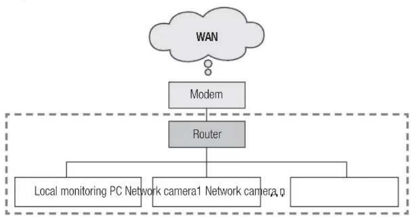
EX1)
flowchart
graph TD
    A["WAN"] --> B["Modem"]
    B --> C["Router"]
    C --> D["Local monitoring PC Network camera1"]
    C --> E["Network camera1"]
    C --> F["Network camera"]
EX2)
flowchart
graph TD
    WAN[" WAN "] --> Modem[" Modem "]
    WAN --> Router[" Router "]
    Router --> LocalMonitoring[" Local monitoring PC Network camera 1 "]
    Router --> NetworkCamera1[" ... "]
    Router --> NetworkCameran[" ... "]
    Router --> Hub[" Hub "]
    Modem --> Node1[" Node "]
    Modem --> Node2[" Node "]
    Modem --> Node3[" Node "]
    Modem --> Node4[" Node "]
    Modem --> Node5[" Node "]
    Modem --> Node6[" Node "]
    Modem --> Node7[" Node "]
    Modem --> Node8[" Node "]
    Modem --> Node9[" Node "]
    Modem --> Node10[" Node "]
    Modem --> Node11[" Node "]
    Modem --> Node12[" Node "]
    Modem --> Node13[" Node "]
    Modem --> Node14[" Node "]
    Modem --> Node15[" Node "]
    Modem --> Node16[" Node "]
    Modem --> Node17[" Node "]
    Modem --> Node18[" Node "]
    Modem --> Node19[" Node "]
    Modem --> Node20[" Node "]
    Modem --> Node21[" Node "]
    Modem --> Node22[" Node "]
    Modem --> Node23[" Node "]
    Modem --> Node24[" Node "]
    Modem --> Node25[" Node "]
    Modem --> Node26[" Node "]
    Modem --> Node27[" Node "]
    Modem --> Node28[" Node "]
    Modem --> Node29[" Node "]
    Modem --> Node30[" Node "]
    Modem --> Node31[" Node "]
    Modem --> Node32[" Node "]
    Modem --> Node33[" Node "]
    Modem --> Node34[" Node "]
    Modem --> Node35[" Node "]
    Modem --> Node36[" Node "]
    Modem --> Node37[" Node "]
    Modem --> Node38[" Node "]
    Modem --> Node39[" Node "]
    Modem --> Node40[" Node "]
    Modem --> Node41[" Node "]
    Modem --> Node42[" Node "]
    Modem --> Node43[" Node "]
    Modem --> Node44[" Node "]
    Modem --> Node45[" Node "]
    Modem --> Node46[" Node "]
    Modem --> Node47[" Node "]
    Modem --> Node48[" Node "]
    Modem --> Node49[" Node "]
    Modem --> Node50[" Node "]
    Modem --> Node51[" Node "]
    Modem --> Node52[" Node "]
    Modem --> Node53[" Node "]
    Modem --> Node54[" Node "]
    Modem --> Node55[" Node "]
    Modem --> Node56[" Node "]
    Modem --> Node57[" Node "]
    Modem --> Node58[" Node "]
    Modem --> Node59[" Node "]
    Modem --> Node60[" Node "]
    Modem --> Node61[" Node "]
    Modem --> Node62[" Node "]
    Modem --> Node63[" Node "]
    Modem --> Node64[" Node "]
    Modem --> Node65[" Node "]
    Modem --> Node66[" Node "]
    Modem --> Node67[" Node "]
    Modem --> Node68[" Node "]
    Modem --> Node69[" Node "]
    Modem --> Node70[" Node "]
    Modem --> Node71[" Node "]
    Modem --> Node72[" Node "]
    Modem --> Node73[" Node "]
    Modem --> Node74[" Node "]
    Modem --> Node75[" Node "]
    Modem --> Node76[" Node "]
    Modem --> Node77[" Node "]
    Modem --> Node78[" Node "]
    Modem --> Node79[" Node "]
    Modem --> Node80["Node"]
checking network configuration
EX3)
flowchart
graph TD
    A["WAN"] --> B["Modem"]
    B --> C["Router"]
    C --> D["Hub"]
    D --> E["Local monitoring PC Network camera 1"]
    D --> F["..."]
EX4)
flowchart
graph TD
    WAN[" WAN "] --> Modem[" Modem "]
    Modem --> Router[" Router "]
    Router --> Hub[" Hub "]
    Router --> NetworkCamera1[" Network camera 1 Network camera n "]
    Hub --> LocalMonitoringPC[" Local monitoring PC "]
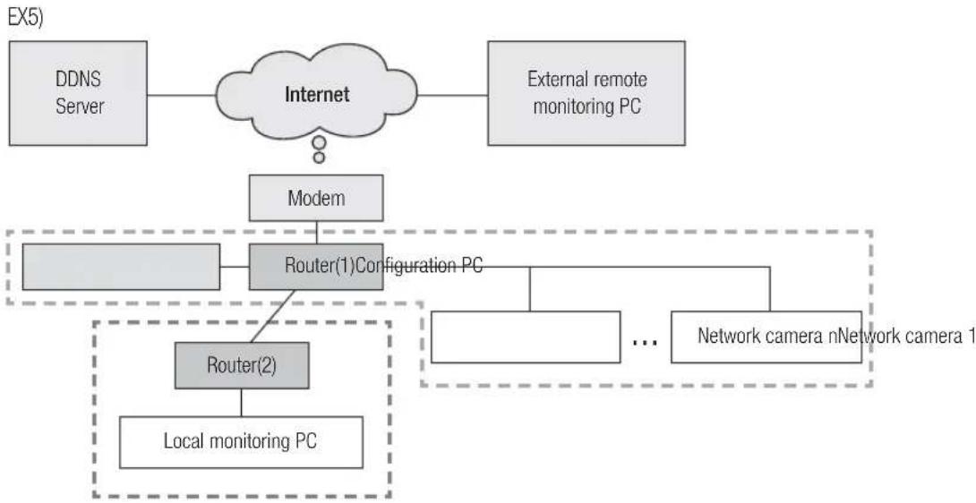
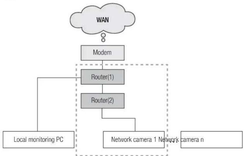
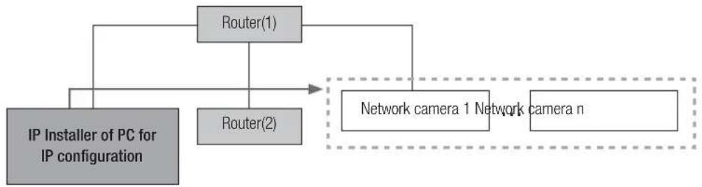
As shown in the image below, if the monitoring PC and network camera are connected to different routers, the network camera cannot be configured, even if the IP installer is installed in the local monitoring PC. In this case, connect the configuration PC or notebook to the router (1) to set up the network camera.
EX5)
flowchart
graph TD
    WAN["WAN"] --> Modem["Modem"]
    Modem --> Router1["Router(1)Configuration PC"]
    Router1 --> Router2["Router(2)"]
    Router2 --> LocalMonitoringPC["Local monitoring PC"]
    Router2 --> NetworkCamera1["Network camera nNetwork camera 1"]
    Router2 --> NetworkCamera2["..."]
    Router2 --> Modem
Remove the PC or laptop for IP configuration after the configuration.
checking network configuration
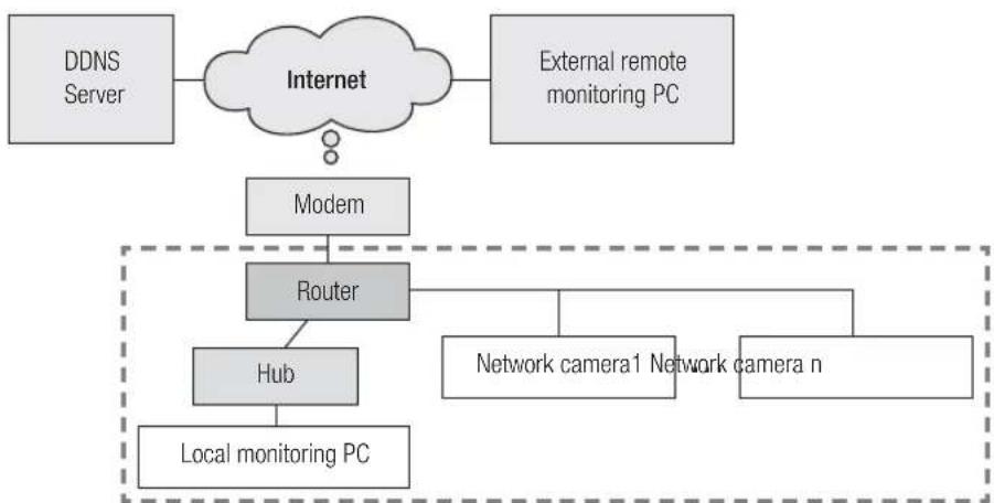
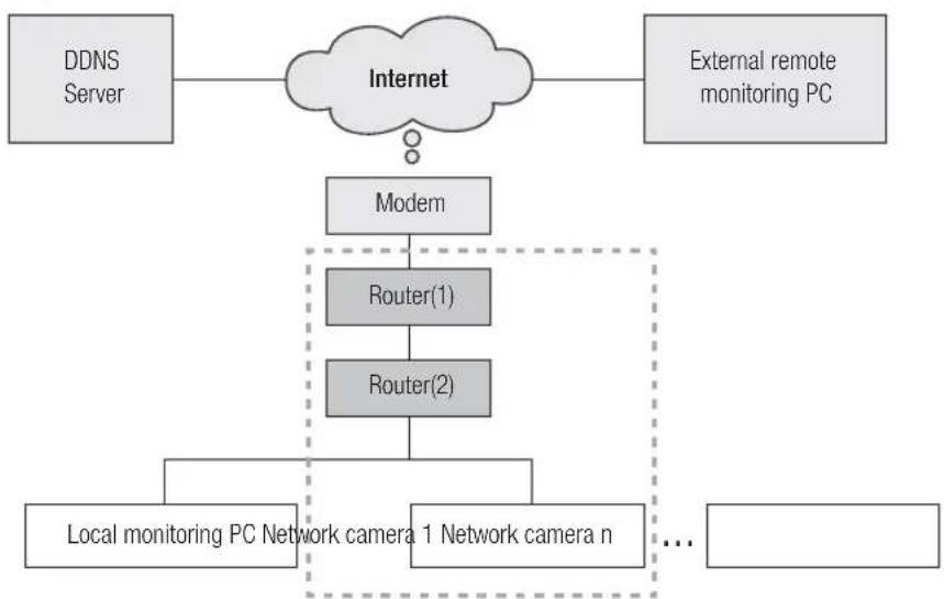
If DDNS server is used:
As shown in the image below, if the monitoring PC and network camera are connected to the same router, they will have the same IP range.
Install the IP Installer on the local PC and use the PC for IP configuration.
EX1)
flowchart
graph TD
    A["DDNS Server"] --> B["Internet"]
    C["External remote monitoring PC"] --> B
    B --> D["Modem"]
    D --> E["Router"]
    E --> F["Local monitoring PC Network camera n"]
    E --> G["Network camera1"]
    E --> H["..."]
EX2)
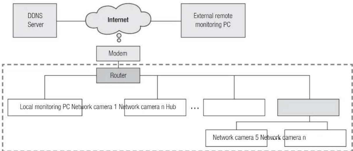
flowchart
graph TD
    A["DDNS Server"] --> B["Internet"]
    C["External remote monitoring PC"] --> B
    B --> D["Modem"]
    D --> E["Router"]
    E --> F["Local monitoring PC Network camera 1 Network camera n Hub ..."]
    E --> G["Network camera 5 Network camera n"]
EX3)
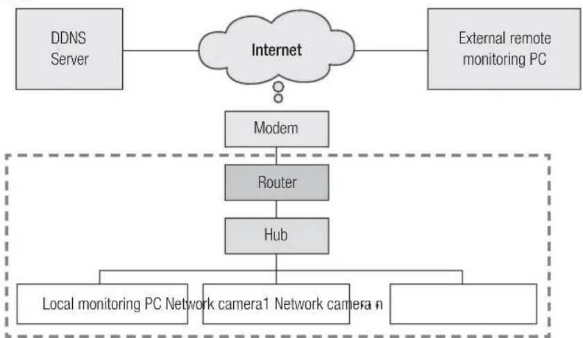
flowchart
graph TD
    A["DDNS Server"] --> B["Internet"]
    C["External remote monitoring PC"] --> B
    B --> D["Modem"]
    D --> E["Router"]
    E --> F["Hub"]
    F --> G["Local monitoring PC Network camera1 Network camera n"]
    F --> H["..."]
EX4)
flowchart
graph TD
    A["DDNS Server"] --> B["Internet"]
    C["External remote monitoring PC"] --> B
    B --> D["Modem"]
    D --> E["Router"]
    E --> F["Hub"]
    F --> G["Local monitoring PC"]
    H["Network camera1"] --> E
    I["Network camera n"] --> E
checking network configuration
As shown in the image below, if the monitoring PC and network camera are connected to different routers, the network camera cannot be configured, even if the IP installer is installed in the local monitoring PC. Connect another PC or laptop for IP configuration to router (1) and configure the network camera.
flowchart
graph TD
    A["DDNS Server"] --> B["Internet"]
    C["External remote monitoring PC"] --> B
    B --> D["Modem"]
    D --> E["Router(1)Configuration PC"]
    E --> F["Router(2)"]
    F --> G["Local monitoring PC"]
    H["Network camera nNetwork camera 1"] --> I["..."]
    style E stroke-dasharray: 5 5
    style F stroke-dasharray: 5 5
    style G stroke-dasharray: 5 5
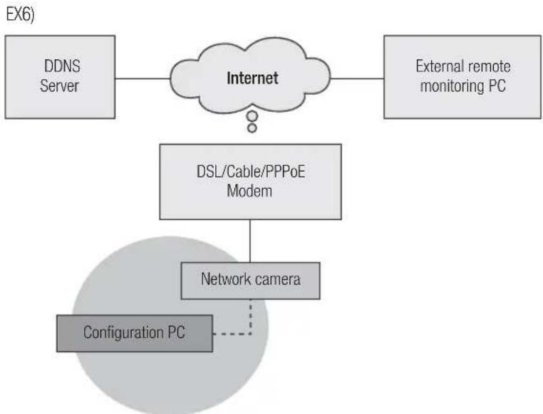
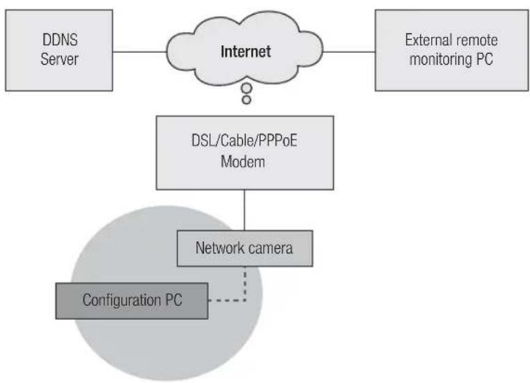
As shown in the image below, if the monitoring PC and the network camera are connected to the DSL/Cable/PPPoE modem directly without connecting to the local network, connect another PC or laptop and use the PC to configure a network camera IP.
flowchart
graph TD
    A["DDNS Server"] --> B["Internet"]
    C["External remote monitoring PC"] --> B
    B --> D["DSL/Cable/PPPoE Modem"]
    D --> E["Network camera"]
    E -.-> F["Configuration PC"]
Remove the PC or laptop for IP configuration after the configuration.
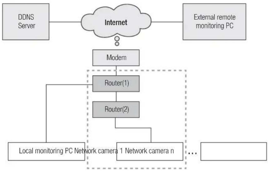
If the network environment makes it difficult to configure an IP for the network camera in a typical way:
As shown in the image below, if two or more routers are located at the upper layer of the network camera, it will generally be impossible to configure the network camera.
In this environment, it is necessary to convert the router (2) into a general hub equipment (by turning off the DHCP function in the Router Setup menu so that the IP addresses of the router (1) and (2) do not crash with each other to make the router (2) operates as it were a general hub equipment) or double port forwarding of the routers (1) and (2).
It is difficult to change and configure the network, so it is recommended to ask the network administrator of the site to replace router (2) with a general hub, and connect the network camera.
EX1)
flowchart
graph TD
    A["DDNS Server"] --> B["Internet"]
    C["External remote monitoring PC"] --> B
    B --> D["Modem"]
    D --> E["Router(1)"]
    D --> F["Router(2)"]
    E --> G["Local monitoring PC Network camera 1 Network camera n"]
    F --> G
    G --> H["..."]
EX2)
flowchart
graph TD
    A["DDNS Server"] --> B["Internet"]
    C["External remote monitoring PC"] --> B
    B --> D["Modem"]
    D --> E["Router(1)"]
    E --> F["Router(2)"]
    F --> G["Local monitoring PC Network camera 1 Network camera n"]
    G --> H["..."]
checking network configuration
EX3)
flowchart
graph TD
    A["WAN"] --> B["Modem"]
    B --> C["Router(1)"]
    B --> D["Router(2)"]
    C --> E["Local monitoring PC"]
    D --> F["Network camera 1 Network camera n"]
    F --> E
EX4)
flowchart
graph TD
    A["WAN"] --> B["Modem"]
    B --> C["Router(1)"]
    B --> D["Router(2)"]
    C --> E["Local monitoring PC Network camera 1 Network camera n"]
    D --> E
    E --> F["..."]
network configuration
How to check the IP range of the router connected to the network camera.
- Click Start → Run Windows in the Windows screen and enter "cmd".
- Type "ipconfig" in the command window. Information about the IP of the PC for IP configuration connected to the router will be displayed.
If the same gateway and subnet mask are used, the IP range is the same because the network camera is connected to the same router.
flowchart
graph TD
    A["Router"] --> B["IP Installer of PC for IP configuration"]
    B --> C["Network camera 1 Network camera n"]
    C --> D["Router"]
    D --> E["Router"]
    style A fill:#f9f,stroke:#333
    style B fill:#ccf,stroke:#333
    style C fill:#cfc,stroke:#333
    style D fill:#fcc,stroke:#333
    style E fill:#ffc,stroke:#333
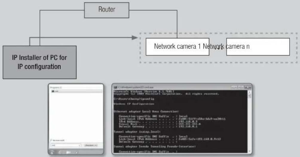
CONFIGURE THE NETWORK ON THE PC USED FOR IP CONFIGURATION
Connect a PC to configure IP
To launch the IP installer program for IP configuration, connect the PC to the same router in order to have the same IP range as the network camera.
If there is a local PC within the same IP range, launch the IP installer on the local PC to configure the network. If there is no local PC within the same IP range, connect another PC to configure an IP.
flowchart
graph TD
    A["IP Installer of PC for IP configuration"] --> B["Router(1)"]
    A --> C["Router(2)"]
    B --> D["Network camera 1 Network camera n"]
    C --> D
network configuration
How to configure the network environment of the PC used for IP configuration
-
Open the network environment configuration menu of the PC connected to the router.
-
Path : Control panel → Network and Sharing Center → Change adapter settings → Local Area Connection → Properties → Internet Protocol Version (TCP/IPv4) → Properties
-
Select "Obtain an IP address automatically" and "Obtain DNS server address automatically."
If the IP range of the PC used for IP configuration is different from that of the network camera, the camera will not be detected, even if you click [Search].

text_image
Local Direct Connection Connect to: Modify PDF/PDF 100 Network Connection To complete access for missing data: □ Make for Virtual Server □ Add or Reduce Access to Virtual Server □ Increase Password (2.573 KB) □ Increase Download Access (2.573 KB) □ Use Layer Download Access (2 KB) □ Use Layer Download Access (2 KB) Send... Browse... Promote: Canadian Direct-based PDF. The PDF with any source packet that is available to the private cloud. Browse to: Canadian Direct Send to: Canadian Direct Access to: Canadian Direct Send to: Canadian Direct Browse to: Canadian DirectLAUNCHING IP INSTALLER
What is IP Installer?
The IP Installer, launched on the PC for IP configuration, receives MAC address information transmitted from the network devices with the IP range of the router, and detects network cameras.
If the IP configuring PC (on which the IP Installer is installed) and the network camera are connected to different routers and their IP ranges are different, the IP Installer cannot detect network cameras.
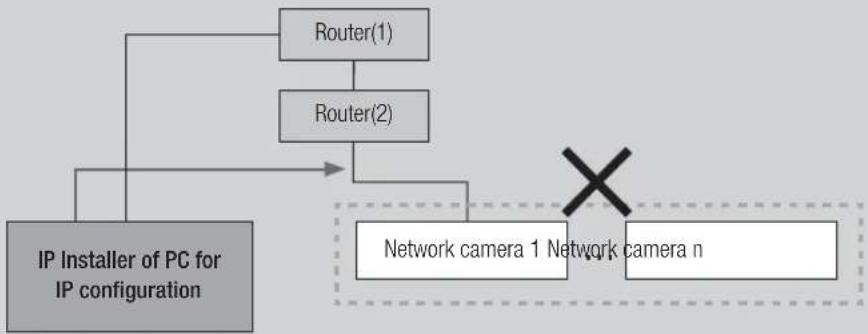
EX1) In the following network structure, a MAC address of the network camera is not transmitted to outside router (2), and a network camera is not detected on the IP Installer of the local PC.
flowchart
graph TD
    A["IP Installer of PC for IP configuration"] --> B["Router(1)"]
    A --> C["Router(2)"]
    B --> D["Network camera 1 Network camera n"]
    C --> D
    D --> E["X"]
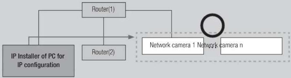
EX2) The IP configuring PC, on which the IP Installer is installed, must be located in the same IP range of the router with the network camera in order to detect network cameras.
flowchart
graph TD
    A["IP Installer of PC for IP configuration"] --> B["Router(1)"]
    A --> C["Router(2)"]
    B --> D["Network camera 1 Network camera n"]
    C --> D
If DDNS server is not used:
In the following case, launch the IP Installer on the local monitoring PC.
EX1)
flowchart
graph TD
    A["WAN"] --> B["Modem"]
    B --> C["Router"]
    C --> D["Local monitoring PC Network camera1"]
    C --> E["Network camera1"]
    C --> F["Network camera"]
EX2)
flowchart
graph TD
    WAN[" WAN "] --> Modem[" Modem "]
    WAN --> Router[" Router "]
    Router --> LocalMonitoring[" Local monitoring PC Network camera 1 "]
    Router --> NetworkCamera1[" Network camera 1 "]
    Router --> NetworkCameran[" Network camera n "]
    Router --> Hub[" Hub "]
    Hub --> NetworkCamera11[" Network camera 1 "]
    Hub --> NetworkCameran2[" Network camera n "]
network configuration
EX3)
flowchart
graph TD
    WAN --> Modem
    WAN --> Router
    WAN --> Hub
    Modem --> Router
    Router --> Hub
    Hub --> LocalMonitoringPCNetworkCamera1
    Hub --> LocalMonitoringPCNetworkCamera2
EX4)
flowchart
graph TD
    A["WAN"] --> B["Modem"]
    B --> C["Router"]
    C --> D["Hub"]
    D --> E["Local monitoring PC"]
    C --> F["Network camera 1 Network camera n"]
In the following case, connect another configuring PC to router (1) and launch the IP Installer.
EX5)
flowchart
graph TD
    WAN["WAN"] --> Modem["Modem"]
    Modem --> Router1["Router(1)Configuration PC"]
    Router1 --> Router2["Router(2)"]
    Router2 --> LocalMonitoring["Local monitoring PC"]
    Router2 --> NetworkCamera1["Network camera nNetwork camera 1"]
    Router2 --> ...[...]
    Router2 --> Modem
If DDNS server is used:
In the following case, launch the IP Installer on the local monitoring PC.
EX1)
flowchart
graph TD
    A["DDNS Server"] --> B["Internet"]
    C["External remote monitoring PC"] --> B
    B --> D["Modem"]
    D --> E["Router"]
    E --> F["Local monitoring PC Network camera n"]
    E --> G["Network camera1"]
    E --> H["..."]
EX2)
flowchart
graph TD
    A["DDNS Server"] --> B["Internet"]
    C["External remote monitoring PC"] --> B
    B --> D["Modem"]
    D --> E["Router"]
    E --> F["Local monitoring PC Network camera 1 Network camera n Hub"]
    E --> G["..."]
    E --> H["Network camera 5 Network camera n"]
network configuration
EX3)

flowchart
graph TD
    A["DDNS Server"] --> B["Internet"]
    C["External remote monitoring PC"] --> B
    B --> D["Modem"]
    D --> E["Router"]
    E --> F["Hub"]
    F --> G["Local monitoring PC Network camera1 Network camera R"]
    F --> H["..."]
EX4)
flowchart
graph TD
    A["DDNS Server"] --> B["Internet"]
    C["External remote monitoring PC"] --> B
    B --> D["Modem"]
    D --> E["Router"]
    E --> F["Hub"]
    F --> G["Local monitoring PC"]
    H["Network camera1 Network camera n"] --> E
    style H stroke-dasharray: 5 5
In the following case, connect another configuring PC to router (1) and launch the IP Installer.
EX5)
flowchart
graph TD
    A["DDNS Server"] --> B["Internet"]
    C["External remote monitoring PC"] --> B
    B --> D["Modem"]
    D --> E["Router(1)Configuration PC"]
    E --> F["Router(2)"]
    F --> G["Local monitoring PC"]
    E --> H["..."]
    E --> I["Network camera nNetwork camera 1"]
In the following case, connect the configuring PC directly to the network camera and launch the IP Installer.
EX6)
flowchart
graph TD
    A["DDNS Server"] --> B["Internet"]
    C["External remote monitoring PC"] --> B
    B --> D["DSL/Cable/PPPoE Modem"]
    D --> E["Network camera"]
    E -.-> F["Configuration PC"]
network configuration
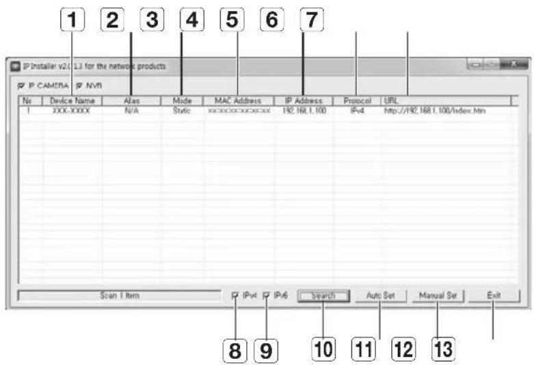
Buttons used in IP Installer
text_image
1 2 3 4 5 6 7 IP Installer v2( L3 for the network products IP CAMERA NPVI No Device Name Alas Made MAC Address IP Address Protocol URL 1 XXX-XXXX N/A Static xxxxxxxxxxxxxxxxx 192.168.1.100 IPv4 http://192.168.1.100/index.htm Scan 1 item IPv4 IPv6 Search Auto Set Manual Set Exit 8 9 10 11 12 13| Item Description | ||
| 1 | Device Name | Model name of the connected camera.Click the column to sort the list by model name.However, search will be stopped if clicked during the search. |
| 2 | Alias This function is not currently implemented. | |
| 3 | Mode | Displays either, or for the current network connection status. |
| 4 | MAC(Ethernet) Address | Ethernet address for the connected camera.Click the column to sort the list by Ethernet address.However, search will be stopped if clicked during the search. |
| 5 | IP Address | IP address.Click the column to sort the list by IP address.However, search will be stopped if clicked during the search. |
| 6 | Protocol | Network setting for the camera.The factory default is “IPv4”.Cameras with the IPv6 setting will be displayed “IPv6”. |
| 7 | URL | DDNS URL address enabling access from the external Internet.However, this will be replaced with theof the camera if DDNS registration has failed. |
| 8 | IPv4 Scans for cameras with the IPv4 setting. | |
| 9 | IPv6 | Scans for cameras with the IPv6 setting.Activated in an IPv6 compliant environment only. |
| 10 | Search | Scans for cameras that are currently connected to the network.However, this button will be grayed out if neither IPv4 nor IPv6 is checked. |
| Item Description | |
| 11 Auto Set The IP Installer automatically configures the network settings. | |
| 12 Manual Set You should configure the network settings manually. | |
| 13 Exit Exits the IP Installer program. | |
CONFIGURING IP INSTALLER VALUES
How to configure with a static IP
Notice for Setup with a Static IP
If assigning a static IP to the network camera: If the range of the assigned static IP is close to that of network devices (such as PC and printer to which IP addresses are assigned), it may cause an IP assignment error or an IP collision with other network devices after the router is turned off/on or reset. For this reason, it is recommended to assign IP addresses that are not usually used in other network devices. Ex) If network devices such as printer and PC use between 192.168.1.1 and 192.168.1.10 in the router: The network camera should use between 192.168.1.101 and 192.168.1.200.
How to configure IP manually using [Manual Set]:
- Launch the IP Installer on the PC for IP configuration.
- Click the [Search] button. A list of network devices using IP addresses located at the same router is displayed.
- Check the MAC address information and select a device to configure.
- Click the [Manual Set] button. A window to configure an address and port pops up.
- Enter the IP range information assigned by the network administrator or the IP range information (IP Address, Subnet Mask, Gateway, HTTP Port, Device Port) that you want to assign.
- Type the password authentication number for camera access and click the [OK] button. Configuration is now complete.
![Hanwha SNV-8080 - How to configure IP manually using [Manual Set]: - 1](/content/2026/05/1129869/images/de9a4d655c715468634998164958e75f8a644718a40ec0f1592e86d3611a3b4c.jpg)
text_image
P Camera v1.2.1 in the network products P C: CAMERA NVR Type: C:\Program Files\NVR A: 0.5 B: 0.5 C: 0.5 D: 0.5 E: 0.5 F: 0.5 G: 0.5 H: 0.5 I: 0.5 J: 0.5 K: 0.5 L: 0.5 M: 0.5 N: 0.5 O: 0.5 P: 0.5 P: 0.5 P: 0.5 P: 0.5 P: 0.5 P: 0.5 P: 0.5 P: 0.5 P: 0.5 P: 0.5 P: 0.5 P: 0.5 P: 0.5 P: 0.5 P: -1.2.1 P: -1.2.1 P: -1.2.1 P: -1.2.1 P: -1.2.1 P: -1.2.1 P: -1.2.1 P: -1.2.1 P: -1.2.1 P: -1.2.1 P: -1.2.1 P: -1.2.1![Hanwha SNV-8080 - How to configure IP manually using [Manual Set]: - 2](/content/2026/05/1129869/images/6d3133e7ec577496cf7156fa9bc092b74ed640c1fd526066bd51f66c5d1df4d4.jpg)
text_image
Manual Setting Address PPVB DHCP STATIC MAC Address XXXXXXXXXX IP Address 192 168 1 100 Subnet Mask 255 255 255 0 Gateway 192 168 1 1 Password Port HTTP Port 80 Device Port 4320 OK Cancelnetwork configuration
The password for camera access is identical to the "admin" login password. Default value is "4321".
In the IP installer, you can use the initial password, "4321" to set IP Address, Subnet Mask, Gateway, HTTP Port, Device Port, IP type. After changing the network interface, for better security, access the web viewer and change the password.
■For the security purposes, you are recommended to use a combination of numbers, alphabets uppercase and lowercase and special characters for your password.
- HTTP Port is used to connect to the camera using web browser. Default value is "80".
■Device Port is to control video transmission. Default value is "4520".
How to configure an IP address automatically using [Auto Set]:
-
Launch the IP Installer on the PC for IP configuration.
-
Click the [Search] button. A list of network devices using IP addresses located at the same router is displayed.
-
Check the MAC address information and select a device to configure.
-
Click on the [Auto Set] button. [Auto Setting] window with IP Address, Subnet Mask and Gateway entered pops up.
-
Type the password authentication number for camera access and click the [OK] button. Configuration is now complete.
The password for camera access is identical to the "admin" login password. Default value is "4321".
In the IP installer, you can use the initial password, "4321" to set IP Address, Subnet Mask, Gateway, HTTP Port, Device Port, IP type. After changing the network interface, for better security, access the web viewer and change the password.
![Hanwha SNV-8080 - How to configure an IP address automatically using [Auto Set]: - 1](/content/2026/05/1129869/images/752d861a3f76358212717419130dce440b854aa7e27b7df64eb0a812eeba0a7b.jpg)
text_image
P Inster e2.1.1 in the network products P CAXERA S/A No. 100.0000 Access Status Date: 09/03/2023 IP Address: IP4 Preload: 1.0% IP4 IP4-07 IP4-1.08(All, Inc) Draw Item Post IP4 Search Tools Set Manual Set Help![Hanwha SNV-8080 - How to configure an IP address automatically using [Auto Set]: - 2](/content/2026/05/1129869/images/85ff284e8478baf397a221193d47de95a9774682dabff08b47a30cbeb736e476.jpg)
text_image
Auto Setting Network Information IP Address 192 , 168 , 1 , 254 Subnet Mask 255 , 255 , 255 , 0 Gateway 192 , 168 , 1 , 1 ✓ IP Setting ☐ Port Mapping Password OK Cancel■For the security purposes, you are recommended to use a combination of numbers, alphabets uppercase and lowercase and special characters for your password.
■Device Port is to control video transmission. Default value is "4520".
Notice for Installer Setup
- If two or more network cameras are connected to the router, you should configure the IP and port-related parts differently.
| Category Camera #1 Camera #2 | |||
| IP related settings | IP Address | 192.168.1.100 | 192.168.1.101 |
| Subnet Mask | 255.255.255.0 | 255.255.255.0 | |
| Gateway | 192.168.1.1 | 192.168.1.1 | |
| Port related settings | HTTP Port | 8080 | 8081 |
| Device Port | 4520 | 4521 | |
- If the
is set other than 80, you must provide the number in the address bar of the Internet browser before you can access the camera ex) http://IP address : HTTP Port → http://192.168.1.100:8080)
How to configure with a dynamic IP
Notice for Setup with a Dynamic IP
A dynamic IP allows you to use IP address resources effectively. It is needed when assigning an IP address using a DHCP server in a LAN environment, when assigning an IP address using a DHCP of a router in a local network, or when connecting a network camera to a modem that supports DHCP.
If the network camera is set to use a dynamic IP, the monitoring PC program in the local network environment or in an external remote location may not detect the network camera. This is because IP and port may be changed when the router power is reset or recovered from a failure. To solve such problems, it is recommended to set up the port forwarding in the higher router layer. Refer to "How to configure port forwarding" to learn more about how to configure port forwarding. (Page 23)
network configuration
How to check and configure a dynamic IP address
-
Launch the IP Installer on the PC for IP configuration.
-
Click the [Search] button.
A list of network devices, whose IP addresses were assigned by the DHCP of the IP router located at the same router, is displayed.
-
Check the MAC address information and select a device to configure.
-
Click the [Manual Set] button. You can check assigned IP from DHCP in the generated window.
-
Click the [OK] button. Configuration is now complete.

The password for camera access is identical to the "admin" login password. Default value is "4321".
text_image
P HOLE: 01.1.1 In the relevant products P C:\DATA\W No. | Document Type | type | Name | MS Address | P Address | Project | Help 1 XXXX300 24 System: or system.mation 完成1项 P4 按2位键1按钮即可关 Start Item P End P Mid Start Sub Set Manual Set End
text_image
Manual Setting Address DHCP STATIC MAC Address xxxxxxxxxxxxxx IP Address 192 168 1 100 Subnet Mask 255 255 255 0 Gateway 192 168 1 1 Password OK Cancel Port HTTP Port 80 Device Port 4520In the IP installer, you can use the initial password, "4321" to set IP Address, Subnet Mask, Gateway, HTTP Port, Device Port, IP type. After changing the network interface, for better security, access the web viewer and change the password.
For the security purposes, you are recommended to use a combination of numbers, alphabets uppercase and lowercase and special characters for your password.
- HTTP Port is used to connect to the camera using web browser. Default value is "80".
■Device Port is to control video transmission. Default value is "4520".
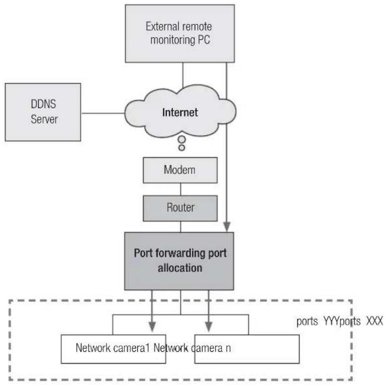
What is port forwarding?
If using a dynamic IP through the DHCP configuration of a router, the port forwarding function allows the router to assign a static IP and camera for a specific network camera when a monitoring PC program connects to a specific network camera.
In addition, when the router power is reset or recovered from a failure and its IP and port are changed, it prevents the monitoring PC program from not finding its network camera.
When a monitoring PC program connects to an internal network camera using a DDNS server, port forwarding must be set. If the network camera's IP and port are not configured through port forwarding, a connection cannot be made.
flowchart
graph TD
    A["External remote monitoring PC"] --> B["Internet"]
    C["DDNS Server"] --> B
    B --> D["Modem"]
    D --> E["Router"]
    E --> F["Port forwarding port allocation"]
    F --> G["Network camera1 Network camera n"]
    F --> H["ports YYYports XXX"]
network configuration
flowchart
graph TD
    A["External remote monitoring PC"] --> B["Internet"]
    C["DDNS Server"] --> B
    B --> D["Modem"]
    D --> E["Router"]
    E --> F["Network camera1"]
    E --> G["Network camera n"]
    F --> H["X"]
    G --> I["X"]
    H --> J["..."]
    I --> K["..."]
Setting up Port Range Forward for several network cameras
When several network cameras are connected to one Broadband Router device, you should forward the TCP 943 port of the router to the TCP 943 port of a connected camera.
flowchart
graph TD
    A["User"] --> B["Internet"]
    B --> C["Broadband Router"]
    C --> D["Start End Protocol IP Address"]
    C --> E["943 943 TCP 192.1 68.1.100"]
    C --> F["3000 3000 TCP/UDP 192.168.1.100"]
    C --> G["3001 3001 TCP/UDP 192.168.1.101"]
    C --> H["4520 4520 TCP/UDP 192.168.1.100"]
    C --> I["4521 4521 TCP/UDP 192.168.1.101"]
    C --> J["8080 8080 TCP/UDP 192.168.1.100"]
    C --> K["8081 8081 TCP/UDP 192.168.1.101"]
    L["Camera1 (192.168.1.100)"] --> M["HTTP Port 8080"]
    L --> N["Device port 4520"]
    L --> O["RTSP Port 3000"]
    L --> P["Policy Server Port 943"]
    Q["Camera2 (192.168.1.101)"] --> R["HTTP Port 8081"]
    Q --> S["Device port 4521"]
    Q --> T["RTSP Port 3001"]
    Q --> U["Policy Server Port 943"]
TCP 943 port is a port for the Silverlight policy server of a camera, you cannot change the Silverlight policy server port of a camera.
■Set manually in router setup menu to set port forwarding.
Port forwarding can be done without additional router setup if the router supports the UPnP (Universal Plug and Play) function.
After connecting the network camera, set
How to configure the CISCO router
-
From the Setup menu of the Broadband Router, select
- . For setting the port range forward for a third-party Broadband Router, refer to the user guide of that Broadband Router. -
Select
and for each connected camera to the Broadband Router. Each port number for the Broadband Router should match that specified in - - from the camera's web viewer menu. -
When done, click [Save Settings]. Your settings will be saved.
text_image
Screenshot of Windows Broadband Router with Synculator interface, showing port configuration settings and system status indicators.- Above sample instructions are based on the CISCO's Broadband Router. - The settings may differ depending on the connected Broadband Router model. For more information, refer to the user manual of the applicable router.
network configuration
Setting page addresses for each router manufacturer and how to log in to each router
The following information may be subject to change by the manufacturer.
| Router Manufacturer Setting page IP address ID / Password | ||
| Samsung http://192.168.123.254 admin/admin | ||
| Zio http://192.168.10.1 | ||
| Wavecast http://192.168.200.254 | http://192.168.25.1 | admin/admin |
| Linksys http://192.168.1.1 admin/1234 blank/admin | ||
| Belkin http://192.168.2.1 | ||
| Netgear http://192.168.0.1 admin/password | admin/1234 | |
| Netop http://192.168.0.1 admin/admin | ||
| Neple http://192.168.10.1 admin | ||
| Levelone | http://192.168.123.254 | |
| NETWEEN | http://192.168.1.1 admin/admin | |
| NEXT | http://192.168.100.1http://192.168.0.1 | |
| Imation http://192.168.10.1 | ||
| ASUS | http://192.168.10.1 | |
| SMC | http://192.168.2.1 smcadmin | |
| iptime http://192.168.0.1 | ||
| QookHub | http://172.30.1.254 | ktuser/megaap |
| HomeHub | http://172.30.1.254:8899 | ktroot/nespot |
| LGU+ (model name NAPL,CAPL) | http://192.168.123.254 admin | |
| MyLGtv | http://192.168.219.1 | user/poweradmin/power |
| Sktelesys | http://192.168.15.1:62207 | root/skb_ipdcp |
| SK broadband(DVW-2000N) | http://192.168.25.1 admin/admin | |
| SKtv (MW-2010R) | http://192.168.20.1 admin/skbiptv | root/1234 or admin |
| Anygate | http://192.168.10.1 | |
| Buffalo | http://192.168.11.1 root/blank | |
| Unicorn | http://192.168.123.254 admin or admin/admin | |
| LG axler | http://192.168.10.1 | |
| D-link | http://192.168.0.1 | admin/blank |
How to enter the port forwarding menu of each router manufacturer

The following information may be subject to change by the manufacturer.
| Router Manufacturer Enter the settings menu of each | |
| Samsung | Advanced Settings → Forwarding → Virtual Server (Port forwarding) |
| Zio | NAT → Port forwarding |
| Wavecast | Advanced Settings → Port forwarding, Firewall → Port forwarding |
| Linksys | Applications & Gaming → Port Range Forward |
| Belkin | Firewall → Virtual Server |
| Netgear | Advanced → Port forwarding → Add Custom Service |
| Netop | Firewall settings → Virtual server settings |
| Neple | Advanced feature settings → Virtual server |
| Levelone | Forwarding rule → Virtual server |
| NETWEEN | Advanced settings → NAT → Port forwarding |
| NEXT | NAT → Virtual server (Port forwarding) |
| Imation | Advanced feature settings → Virtual server |
| ASUS | NAT settings → Virtual server |
| SMC | Advanced settings → NAT → Virtual server settings |
| iptime | Administrative tools → Advanced settings → Port forwarding settings |
| QookHubHomeHub | Advanced settings → Traffic management → Port forwarding settings |
| LGU+ (model name NAPL,CAPL) | Advanced settings → NAT settings → Port forwarding |
| MyLGtv | Network settings → NAT settings → Port forwarding at the bottom |
| Sktelesys | Firewall → Policies → Port Forwarding |
| SK broadband (DVW-2000N) | Firewall → Port forwarding |
| SKtv (MW-2010R) | NAT → Port Forwarding |
| Anygate | Expert settings → Traffic management → Port forwarding |
| Buffalo | Game port → Port forwarding |
| Unicorn | Virtual server → Port forwarding, Port forwarding → Virtual server |
| LG axler | Advanced menu → Port forwarding |
| D-link | Advanced → Port forwarding (or virtual server) |
network configuration
LOGIN
Login by connecting to a network camera.
Camera connection (login) through the IP Installer
- Launch the IP Installer.
- Click the [Search] button to find connected cameras.
- Select the network camera that you want to connect and double-click on it. An Internet browser is launched.
- Enter the
and to login when the login window appears.
text_image
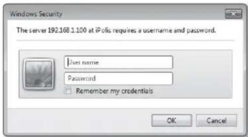
F:\testor.c1.1.1 in the remote products F:\CABRERA - SIRI File Path: 1000 KBX Size: 5/3 Name: 1000 KBX IP address: 1000 KBX IP address: 1000 KBX IP address: 1000 KBX IP address: 1000 KBX IP address: 1000 KBX IP address: 1000 KBX IP address: 1000 KBX IP address: 1000 KBX IP address: 1000 KBX IP address: Search Add Set Medical Set ExitCamera connection (login) through the Internet browser)
- Launch the Internet browser.
- Enter the IP address of the network camera in the address bar. Ex) IP address (IPv4): http://192.168.1.100 IP address (IPv6): [2001:230:abcd:ffff:0000:0000:ffff:1111]
- If HTTP port is not '80', enter the IP address and HTTP port number of the network camera. Ex) Enter "http://192.168.1.100:8080"
- Enter the
and to login when the login window appears.
text_image
Windows Security The server iPole 192.168.1.10 at iPole requires a username and password. User name Password Remember my credentials OK CancelDescription of DDNS Server Operation
1. Main DDNS-related information
- DDNS URL address: http://www.samsungipolis.com/Product ID
2. DDNS server operation
① To use the Samsung DDNS, visit the iPOLiS homepage (www.samsungipolis.com) and login with the product ID of camera 1/camera 2 installed in the site.
② Sign up for a membership and register your product on the DDNS server.
③ Connect the camera 1/camera 2 through the webview.
You may check the option of Samsung DDNS activation in the DDNS configuration menu to use the DDNS.
The camera periodically transmits its own IP address to the DDNS server on the network once a camera product ID is registered on the DDNS server and the camera DDNS option is activated.
- When an external remote monitoring PC attempts to connect to camera 1/camera 2 for the purpose of monitoring, it connects to the DDNS server to receive the latest address of camera 1/camera 2.
■The external remote monitoring PC receives the latest IP address from the DDNS server and connects to camera 1/camera 2 using the latest IP address to receive video images.
flowchart
graph TD
    A["DDNS Server"] --> B["Internet"]
    C["External remote monitoring PC"] --> B
    B --> D["Modem"]
    D --> E["Router"]
    E --> F["Network camera 1"]
    E --> G["Network camera n"]
    F --> H["..."]
    G --> I["..."]
    H --> J["2"]
    I --> K["3"]
    J --> L["3"]
    K --> M["4"]
    L --> N["1"]
    M --> O["4"]
    N --> P["5"]
    O --> Q["5"]
| 1 | Register the product on the DDNS server. |
| 2 | Connect to camera 1/camera 2 through the webviewer and check the option of Samsung DDNS activation. |
| 3 | Camera1/ camera 2 periodically transmits its own IP address to the DDNS server. |
| 4 | It connects to the DDNS server to receive the latest address of camera 1/camera 2. |
| 5 | The external remote monitoring PC receives the latest IP address from the DDNS server and connects to camera 1/ camera 2 using the latest IP address to receive video images. |
network configuration
Log in the camera by using a remote PC through the DDNS server
DDNS registration
- Visit the Samsung DDNS Site http://www.samsungipolis.com to sign up for a membership.
text_image
Welcome to the IPOLIS website. We offer various services for users of Samsung's POLIS network products. To use the services, please register that Terms of Service Terms of Service (All Membership Agreement) Chapter 1.1 Parties and Recitals 1.1 Purpose of Terms of Service The following terms and conditions given the IPOLISMembership (www.ansunogpies.co.uk) posted by Samsung Tachwin Limited Company (the "Company") and the benefits available thereunder (the "Services"). 1.2 Implementation and Review of Terms of Service 1.2.1 This Terms of Service will be effective by announcement on the Service or notification through email to the individual Room. 1.2.2 The Company may review the agreement without your notice to the Members in case of crucial situation and the review terms and conditions set out to effective with notification at the same member directed in [1, 1, 1] 1.2.3 If any handset in disagreement with the revised forms and conditions can request Fremdkert; otherwise, the Decisions will treat Member's use as accordance of the revised terms and conditions have flow continue to benefit the Agree NEXT 8- From the top menu bar, select
- .

text_image
iPOLiS WHAT IS POLiS PRODUCT DOGS SERVICE MY GENE DORS SERVICE NEXT TAG NETWORK SEC THE FIRST ORDER OF THE DIRECT NETFLAMERS-
Click [PRODUCT REGISTRATION].
-
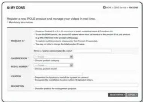
Enter the product ID. ■You must perform the duplicate check for the ID that you entered.
text_image
MY DDNS HOME + DDNS SERVICE + MYDDNS Current product list is displayed. If wanted product is not in the list, click 'Product Registration' at the bottom. NO Product ID MODEL LOCATION STATUS VIEW MANAGEMENT INFO TAG nothing PRODUCT REGISTRATION-
Select a
and specify the . -
Specify the product location with a description if necessary.
-
Click [REGISTRATION].
text_image
My DDNS Register a new IPOLS product and manage your videos in real time. * Mandatory Information PRODUCT IS * • Choose and Product ID or to its structure in length matching frames & 50 seconds if it is • To use the DDNS service, the product ID entered above must be listed to the product ID of your product (e.g. SMC-076) based on the product sheeting page. • To install multiple products, please order from Product ID successfully. • You may not able to change the initial product if name. http://www.xmccmppd.com/? CLASSIFICATION * • Choose product category MODEL NUMBER * • Choose product model LOCATION • Determine the function to install the system in password; • Designate the installation function within 18 alphabet letters. DESCRIPTION • Descriptive product for management purposes MODERNATION CANCELAccessing the network camera connected to the local network.
Since using the IP Installer on a remote computer that is not in the Broadband Router's network cluster is not allowed, users can access cameras within a Broadband Router's network by using the camera's DDNS URL.
- Before you can access a camera in the Broadband Router network, you should have set the port range forward for the Broadband Router.
- Launch an Internet browser on an external remote monitoring PC.
- Type a DDNS URL address (http://www.samsungipolis.com/Product ID) in the address bar to connect to the camera.
- Enter the
and to login when the login window appears.
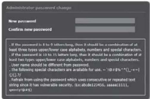
Password setting
When you access the product for the first time, you must register the login password.
When the "Password change" window appears, enter the new password.
text_image
Administrator password change New password Confirm new password . If the password is 8 to 9 letters long, then it should be a combination of at least three types upper/lower case alphabets, numbers and special characters. . If the password is 10 to 15 letters long, then it should be a combination of at least two types upper/lower case alphabets, numbers and special characters. . User name should be different from password. . The following special characters are available for use. ~!@#$%**().+- {}.[-7/- . Refrain from using the password which uses consecutive or repeated text string since it has vulnerable security. (Ex:abode122456, aaaaa11111, qmyty1@#$)For a new password with 8 to 9 digits, you must use at least 3 of the following: uppercase/lowercase letters, numbers and special characters. For a password with 10 to 15 digits, you must use at least 2 types of those mentioned.
Special characters that are allowed.: \~!@#\$%^*()_-+=|{}].?/
■For higher security, you are not recommended to repeat the same characters or consecutive keyboard inputs for your passwords.
If you lost your password, you can press the [RESET] button to initialize the product. So, don't lose your password by using a memo pad or memorizing it.
Login
Whenever you access the camera, the login window appears. Enter the User ID and password to access the camera.
-
Enter "admin" in the
input box. The administrator ID, "admin", is fixed and can not be changed. -
Enter the password in the
input field. -
Click [OK]. If you have logged in successfully, you will the Live Viewer screen.
text_image
Windows Security The server 192.168.1.100 at iPolis requires a username and password. User name Password Remember my credentials OK Cancelnetwork configuration
INSTALLING THE PROGRAM NEEDED TO LAUNCH THE WEBVIEWER AFTER CONNECTING TO NETWORK CAMERA
Installing Silverlight Runtime
If your PC has not installed Silverlight Runtime or has just installed an old runtime version, you will be redirected to the Silverlight Runtime installation page automatically when accessing the web viewer.
To install on Windows OS
- Click
.
text_image
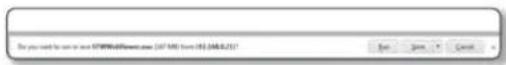
SAMSUNG NETWORK CHINA - Windows Internet Explorer File Edit View Favorites Tools Help Favorites Supported Web - Free Home! < With This Guide > SAMSUNG NETWORK CHINA Subscribe Example Install. Click Here- When the file download dialog pops up, click
.
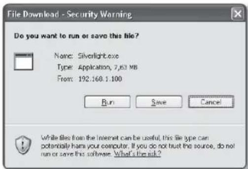
text_image
File Download - Security Warning Do you want to run or save this file? Name: Silverlight.exe Type: Application, 7,63 MB From: 192.160.1.100 Run Save Cancel While files from the Internet can be useful, this file type can potentially harm your computer. If you do not trust the source, do not run or save this software. What's the risk?- When the download is completed, click
.
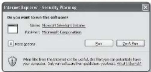
text_image
Internet Explorer - Security Warning Do you want to run this software? Name: Microsoft Silverlight Installer Publisher: Microsoft Corporation More options Run Don't Run While files from the Incomet can be useful, this file type can potentially harm your computer. Only run software from publishers you trust. What is the risk?- The Silverlight Runtime installation page will be displayed.
to proceed with the installation.

text_image
Install Silverlight By adding install now you accept the Silverlight license agreement. View the Silverlight License Agreement Silverlight updates automatically. View the Silverlight Privacy Statement Microsoft® Silverlight® Install now- When done, click
.

text_image
Installation successful You may have to refresh (FS) the Web page for these changes to take effect. CloseTo install on MAC OS
- Run the file trailing with ".dmg".

- Run the install package file automatically created, ending with ".pkg".

text_image
Silverlight_Developer.pkg- Click
.
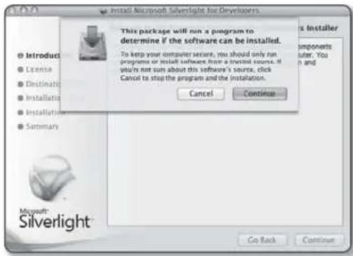
text_image
Install Microsoft Silverlight for Developers This package will run a program to determine if the software can be installed. To keep your computer suite, you should only run programs or install software from a virtual source. If you're not sure about this software's source, click Cancel to stop the program and the installation. Cancel Continue Microsoft Silverlight Go Back Continue- Select your language on the language selection screen, and click
.
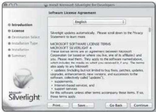
text_image
Microsoft Silverlight for Developers Software License Agreement English Silverlight updates automatically. Please scroll down to the Privacy Statement to learn more. MICROSOFT SOFTWARE LICENSE TERMS MICROSOFT SILVERLIGHT 4 these license terms are an agreement between Microsoft Corporation (or based on where you live, one of its affiliates) and you. Please read them. They apply to the software named above, which includes the media on which you received it, if any. The terms also apply to any Microsoft: • updates (including but not limited to buy fixes, patches, updates, upgrades, enhancements, new versions, and successors to the software, collectively called "updates"). • supplements. • Internet-based services, and • support services for this software, unless other terms accompany those items. If so, those terms apply. Print... Save... Go Back Continue- Click
.

text_image
To continue installing the software you must agree to the terms of the software license agreement. Click Agree to continue or click Disagree to cancel the installation and quit the Installer. Read License Disagree Agree Summary Corporation (for based on where you live, one of its affiliates) and you. Please read them. They apply to the software named above, which includes the media on which you received it, if any. The terms also apply to any Microsoft • updates (including but not invited to bug fixes patches updates, upgrades, enhancements, new versions, and successions to the software, collectively, called "editers"). • supplements. • Internet-based services, and • support services for the software, unless other terms accompany those items. If so these terms apply. Microsoft: Silverlight Print... Save... Go Back... Continuenetwork configuration
- Click
.
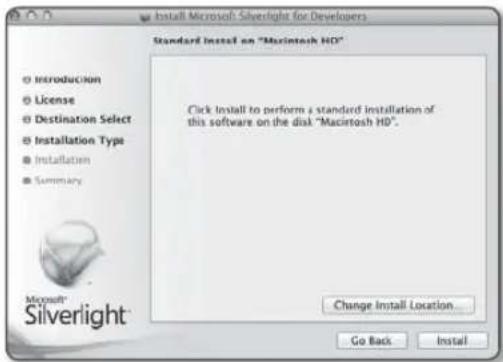
text_image
Install Microsoft Silverlight for Developers Standard Install on "Macintosh HD" Click Install to perform a standard installation of this software on the disk "Macintosh HD". Change Install Location Go Back Install- Enter the password of the account currently logged in, and click
and continue.
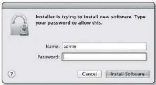
text_image
Installer is trying to install new software. Type your password to allow this. Name: admin Password: Cancel Install Software- Once completed, click
.
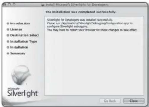
text_image
Install Microsoft Silverlight for Developers The installation was completed successfully. Silverlight for Developers was installed successfully. Please run (Applications/SilverlightDebuggingConfiguration.app to configure Silverlight debugging. You may have to restart your browser for these changes to take effect. Introduction License Destination Select Installation Type Installation Summary Microsoft: Silverlight Go Back CloseInstalling STW WebViewer Plugin
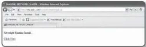
If connecting to a camera for the first time, you will see the installation message. Then, install the required WebViewer Plugin to access the camera and control the video from it in real time.
- When the monitoring page is accessed for the very first time, the installation page is displayed. Click [Click Here] to begin installation.

text_image
http://81.548888/10000000000 SAMSUNG NETWORK.CAL... Network Camera Browser Plugin Installation Update. Click Info! If the plug-in installation file download status is suspended at 99% in the Internet Explorer browser, retry it after selecting "Release SmartScreen filter" in "Tool → SmartScreen filter".
-
Click [Run] in the message window.
-
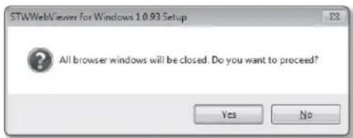
Click [Yes] when the notice window saying that all browser windows will be closed.
-
When the old version of the Web Viewer Plug-in is installed, a notice window saying the old version will be deleted is displayed.
Click [Yes] when the notice window is displayed.
Steps 4 and 5 will be skipped if no Web Viewer Plug-in is installed.
text_image
STWWebViewer for Windows 1.0.93 Setup All browser windows will be closed. Do you want to proceed? Yes No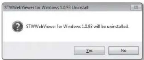
text_image
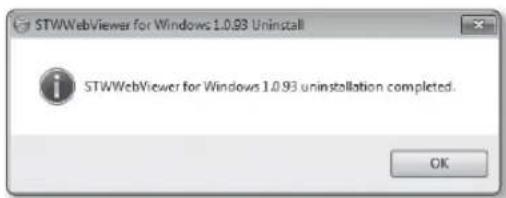
STWWebViewer for Windows 1.0.93 Uninstall ? STWWebViewer for Windows 1.0.93 will be uninstalled. Yes No- Click [OK]. The old version of Web Viewer Plug-in is deleted.
text_image
STWWebViewer for Windows 1.0.93 Uninstall STWWebViewer for Windows 1.0.93 uninstallation completed. OKnetwork configuration
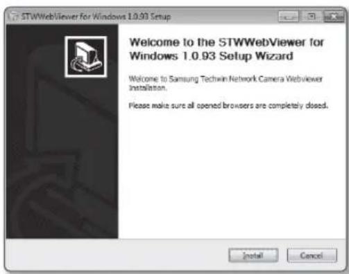
- Click [Install] to begin installation of the Web Viewer Plug-in.
text_image
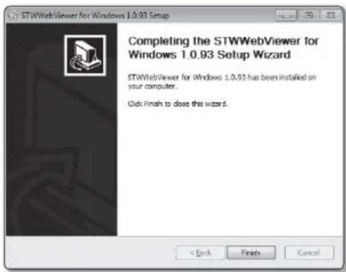
STWWebViewer for Windows 1.0.93 Setup Welcome to the STWWebViewer for Windows 1.0.93 Setup Wizard Welcome to Samsung Techwin Network Camera WebViewer Installation. Please make sure all opened browsers are completely dosed.- Click [Finish].
STW Web Viewer Plug-in installation is completed.
In your internet explorer, if you need to move to the installation screen after installing the STW webviewer plugin, check whether webviewer_activexplugin_lib.control in the "Tool → Additional Function Management" menu is "Activated". If not, and if there is a persisting problem, then select "Tools → Internet Options → General" and delete all the search records.
text_image
STWWebViewer for Windows 1.0.93 Setup Completing the STWWebViewer for Windows 1.0.93 Setup Wizard STWWebViewer for Windows 1.0.93 has been installed on your computer. Click Finish to close this wizard.Using the Live Screen
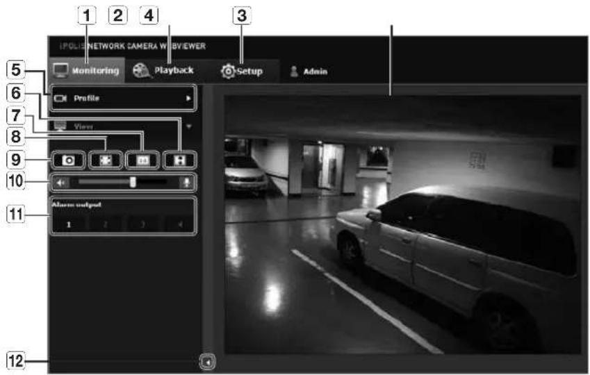
text_image
1 POLIS NETWORK CAMERA WEBVIEWER Monitoring Playback Setup Admin Profile View Alstom output 1 2 3 4 5 6 7 8 9 10 11 Alstom output| Item Description | ||
| 1 | Monitoring Move to the monitoring screen. | |
| 2 | Playback Switch to the monitoring screen that plays recording data in the SD memory. | |
| 3 | Setup Move to the Setup screen. | |
| 4 | Viewer Screen | Displays the Live video on the screen.■You can use the mouse wheel to activate the digital zooming in Viewer screen. |
| 5 | Profile type | You can select a profile type inunder thesetup menu.■When the Web Viewer is connected, the profile information currently using is displayed. |
| 6 | Screen Optimization | The video size of the camera will switch to as big as the Web browser. |
| 7 | Fix the resolution | Regardless of the resolution setup configured in the camera, it sets the resolution to 640x480. Press it again to switch back to the default resolution. |
| 8 | Full Screen Switch the current video to the maximum size of the monitor. | |
| 9 | Capture Saves the snapshot as an image file in the .bmp or .jpg format. | |
| 10 | Audio/Microphone Control | Enable Audio and Microphone are control the Audio volume.■Only the Audio volume can be controlled. |
| 11 | Alarm output Activate the Alarm Out port. | |
| 12 | Hide the context menu | The left-corner context menu will disappear but only the menu icon. |
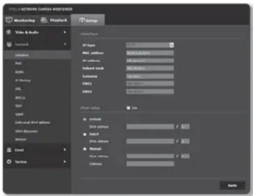
Interface
-
From the Setup menu, select the
-
Click
. -
Set the
and as necessary. -
IP type : Select an IP connection type.
- Manual : Specify the IP address, Subnet mask, Gateway, DNS1, and DNS2.
- DHCP : Specify the DNS1 and DNS2.
- PPPoE : Specify the DNS1, DNS2, ID and Password.
If you set it to, you should specify the IP, Subnet mask, Gateway, DNS 1 & 2 manually.
text_image
PULL NETWORK CAMERA WEBPENER Monitoring Playback Setup Video & Audio Network interface Port DMA1 IP Hosting SSL WSS Ex Grid SNFP Link local SVM address SVM discovery System Event System Interferon IP type: 0.0000 MAC address: 0.0000 to 0.0000 IP address: 0.0000 to 0.0000 Subnet mask: 95.782323 Customize: 16.04417 DMA2: 0.0000 to 0.0000 DMA3: 0.0000 to 0.0000 Print value: Type Default Print address: 1 DSCP Print address: 1 Normal Print address: 1 Castivity: Apply- MAC address : Shows the MAC address.
- IP address : Displays the current IP address.
- Subnet mask : Displays the
for the set IP. - Gateway : Displays the
for the set IP. -
DNS1/DNS2 : Displays the DNS(Domain Name Service) server address.
-
Set the
.
■Set to
- Default : Use the default IPv6 address.
- DHCP : Display and use the IPv6 address obtained from the DHCP server.
-
Manual : Enter IP address and gateway manually and use it.
-
When done, click [Apply (Apply)].
The IP addressing system will be defaulted to DHCP. If no DHCP server is found, the previous settings will be restored automatically.
Once completed with editing, click [Apply (Apply)] to apply changes and the browser exits. After a while, connect again with the changed IP.
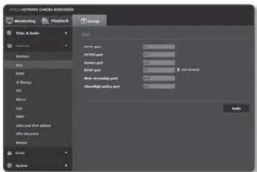
Port
-
From the Setup menu, select the <Network ( ) tab.
-
Click
. -
Type in each item in the Port menu as necessary. ■When setting your ports, you cannot use port numbers such as 0\~1023, 3702 or 49152.
- HTTP port : HTTP port used to access the camera via the web browser. The default is 80(TCP).
Setting the HTTP port for Safari and Google Chrome browsers to 65535 is not allowed by security policy.
text_image
OPOL NETWORK CAMERA WORKOVER Monitoring Playback Setup Video & Audio Settings Host SAMS of Stency MSI WSS to Host GMP Local: the address Other documents Balance Event Systems Name: User port: HSP port: Desktop port: KSP port: Web steering port: Highlight steering port: Audio- HTTPS port : In this version, the security of the web communication protocol HTTP is strengthened. It can be used when you set HTTPS mode in SSL.
The initial value is set to 443(TCP).
The available setting range is 1024\~65535. (For security reasons, in your Safari or Google Chrome browser, you may not use 65535 as your HTTPS port.)
- Device port : Set a port used to transfer video signals with the Samsung protocols.
- RTSP port : Used to transfer videos in the RTSP mode; the default is 554.
- Web streaming port : Used to transfer videos to the Web Viewer; the default is 4520.
• Silverlight policy port : Silverlight is used to permit to acquire a network connection; the default is 943.
If changed the HTTP port, the browser exits.
Afterwards, address should contain the newly assigned HTTP port trailing the IP. ex) IP address: 192.168.1.100, HTTP port : Assigned 8080 → http://192.168.1.100:8080 (If HTTP port is set to 80, no need to specify the port number)
The port range of the Web Streaming is between 4502 and 4534. If the Device port is with this effective range, the Web Streaming port should be specified the same as the Device port.
■You cannot change the Web Streaming/Silverlight policy server port of a camera.
■ Using RTSP and HTTPS is recommended in order to prevent the image information from being restored.
- When done, click [Apply (Apply
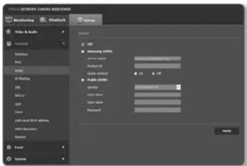
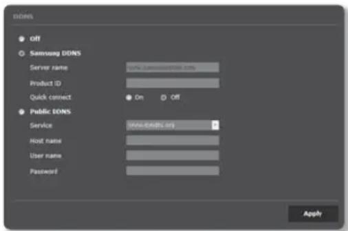
DDNS
DDNS is an abbreviation of Dynamic Domain Name Service that converts the IP address of a camera into a general Host Name so that the user can easily remember it.
You can use the DDNS service only if the internet is connected.
- From the Setup menu, select the <Network ( ▶) tab.
- Click
. - Select the
connection type. - Type in the DDNS items according to the selected type.
- Samsung DDNS : Select this if you use the DDNS server provided by Samsung Techwin.
- Product ID : Enter the product ID that is registered with the Samsung DDNS service.
- Quick connect : It sets port forwarding automatically when used with a UPnP (Universal Plug and Play) supporting router.
text_image
PICKLE NETWORK CAMERA WEBVIEWER Monitoring Playback Video & Audio Network Interface Port DNS IP Flashing DNS ALL to Ctrl Down Lion local Port address User discovery System USE USE USE USE USE USE USE USE USE USE USE USE USE USE USE USE USE USE USE USE USE USE USE USE USE USE USE USE USE USE USE USE USE USE USE USE USE USE USE USE USE USE USE USE USE USE USE USE USE USE Use: Samsung 0.0012.0000.0000.0000.0000.0000.0000.0000.0000.0000.0000.0000.0000.0000.0000.0000.0000.0000.0000.0000.0000.000If you want to use the DDNS service without using a hub that supports the UPnP function, click Quick connect, then go to the hub menu and activate port forwarding for your hub.
For more on how to set port forwarding for your hub, refer to "How to configure port forwarding". (page 23)
- Public DDNS: Select one of provided public DDNS servers when you use a public DDNS server.
- Service : Select desired public DDNS service server.
- Host name : Enter the name of the host that is registered with the DDNS server.
- User name : Enter the user name for the DDNS service.
-
Password : Enter the password for the DDNS service.
-
When done, click [Apply (Apply)].
If selected
To connect to the Samsung DDNS in camera setup
- From the DDNS setup page, set
to . - Provide the
that you registered product ID with the DDNS site. - Click [Apply (Apply)].
When the connection is successfully made, you will see the message of <(Success)> on the screen.
text_image
DOSI Off Samsung DOSI Server name: www.sdsiosci.org Product ID Quick connect On Off Public DOSI Service www.dosisci.org Host name: User name: Password: ApplyConfiguring public DDNS in Camera Settings
- Open the DDNS settings page and select
for . - Enter the corresponding site's host name, user name and password.
- Click [Apply (Apply)] button.
If the connection properly establishes, <(Success)> appears.
- When done, click [Apply (Apply)].
To use DDNS service properly, both DDNS setup and the router's port forwarding setup are required. For port forwarding setup, refer to "How to configure port forwarding". (page 23)
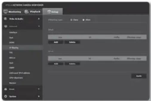
IP filtering
You can create a list of IPs that you want to grant or deny access to them.
- From the Setup menu, select the
tab. - Click
. -
Select
. -
Deny: If selecting this, access from those IPs that are added to the filtering will be restricted.
-
Allow : If selecting this, access from only those IPs that are added to the filtering will be accepted.
-
Click the [Add ( Add )] button.
The IP list will be created.
text_image
PULL NETWORK CAMERA WORKGROUP Monitoring Playback Audio Video & Audio Network Interface Port COM IF Blanking TSL BBL/2x Grid GAIN AMF/CAFL (VNT address) OPF discovery Random Event Systems Filtering types Duty Allow Shift: Max IP Audio Filtering type Add Delete Video: Max IP Audio Filtering type Add Update Audio- Provide the IP that you want to grant or deny access from.
When you enter an IP address and a Prefix, the list of IP addresses available will appear in the right-side filter range column.
If selected
■The IP address of the computer used for the current setup cannot be added to
■Only the IP addresses that are set to
- Select an IP to delete from the list.
Click the [Delete ( )delete ton.
- When done, click [Apply ( )Apply
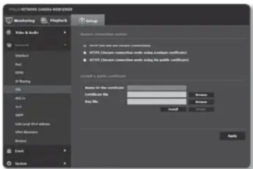
SSL
You can select a secure connection system or install the public certificate for this purpose.
- From the Setup menu, select the
tab. - Click
. - Select a secure connection system.
To access the camera using HTTPS mode, you have to type the IP address for the camera in the form of "https://
text_image
FOLD NETWORK CAMERA WEB/ENGINEER Monitoring Playback Setup Video & Audio User Interface Port DNS IP Floating SQL WBS 2x Word SIMP Link Local Web address Other Discovery Binary Event System Choose connection settings HTTP (Use and use secure connections) HTTPS (Secure connection needs using the analog certificate) HTTPS (Secure connection needs using the public certificate) Browse a public certificate Name for the certificate Certificate file: Buy file: Install Apply- Search for the public certificate that you want to install on the camera.
To install the certificate on the camera, you need to provide a certificate name (it can be arbitrarily assigned by the user), certificate file issued from the certification authority and a key file.
■The
- When done, click [Apply ( )] apply
Installing the certificate
- Enter the certificate name.
- Click the [Browse (Browse)] button, select the public certificate file and key file to be installed, and then click the [Install (Install)
Deleting the certificate
- Click [Delete ( Delete )] button.
- To delete a public certificate, you should access the network video decoder in the mode of
or
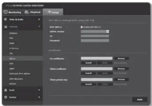
802.1x
When connecting network, you can choose whether using 802.1x protocol, and then install the certification.
- From the Setup menu, select the
tab. - Click <802.1x>.
-
Set the
-
Enable IEEE 802.1x : Specify the use of the 802.1x protocol.
- EAPOL version : Select version 1 or 2.
• ID : Enter the client certificate ID. - Password : Enter the client private key password. If the key file used is not encrypted, you don't need to enter it.
text_image
PDSI NETWORK CAMERA WEB/ECM Monitoring Playback Setup Video & Audio Playnetwork Wireless Port COMS or Missing SSL 400 Hz CHS SPDR LINK/LOEM PH4 address Other Discovery Designer Event Systems HKEY: DOS Max.1e working@EAXA.com (USB 11.1) HKEY Max.1e EAXA version: No Password: Certification: CA certificates: Install... Browse... Client certificates: Install... Browse... Client private key: Install... Browse... ApplyIf the connected network device does not support the 802.1x protocol, the protocol will not operate properly even if you set it.
-
Install/remove the certificate.
-
CA certificates : Select a public certificate that contains the public key.
- Client certificate : Select a public certificate that contains the client certificate key.
-
Client private key : Select a public certificate that contains the client private key.
-
When done, click [Apply (Apply)].
To install/remove 802.1x related certificates
- Press the [Browse (Browse)] button for each item and select a certificate to install.
- If no certificate is installed, you will see "Not Available" appearing next to the selected item.
- Press the [Install ( install) ] button to start installation with a message of "Installed" next to the item.
- Press the [Delete ( ) deletion to remove the certificate.
QoS
You can specify the priority to secure a stable transfer rate for a specific IP.
- From the Setup menu, select the
tab. - Click
. - Click the [Add ( )] button. The IP list will be created.
- Enter an IP address to which you will apply QoS.
The default prefix for IPv4 is 32; For DSCP, the default is set to 63.
■Only the IP addresses that are set to
text_image
PDS NETWORK CAMERA WEBVIEWER Monitoring Playback Audio Video & Audio Interface Appl DCOS IP Streaming SSL WLL in Cell DAIR Link-local IPV address OPV Discovery Balance Event Settings SPs Add Delete SPs Add Delete Apply- Select an IP to delete from the list. Click the [Delete (Delete)] button.
- When done, click [Apply ( )Apply
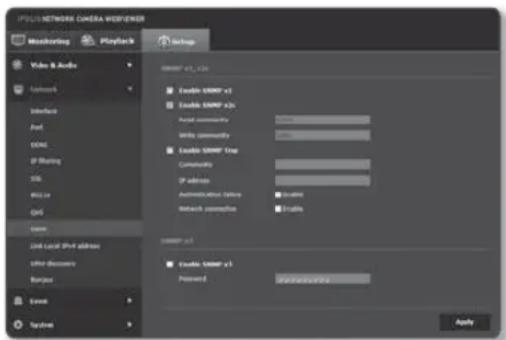
SNMP
With the SNMP protocols, the system or network admin can monitor the network devices on a remote site, and configure the environment settings.
-
From the Setup menu, select the
tab. -
Click
. -
Specify the
. -
Enable SNMP v1 : SNMP version 1 will be active.
- Enable SNMP v2c : SNMP version 2 will be active.
- Read community : Provide the name of the read community where you can access to the SNMP information.
The default name is
text_image
IPVCSNETWORK CAMERA WORKLENSER Measuring Playback Setup Video & Audio Network Interface Port DNS IP Sharing SSL Wi-Fi Grid Event Link Local PDF address Write Discovery Barion Event Systems SNWRP v1, v20 Enable SNMP v1 Enable SNMP v20 Aerial community Write community Enable SNMP Trap Community IP address Authentication Settings Network permission Enable SNWRP v1 Enable SNMP v1 Password Apply- Write community : Provide the name of the write community where you can access to the SNMP information. The default name is
- Enable SNMP Trap : SNMP trap is used to send important events and conditions to the Admin.
- Community : Enter the trap community name to receive messages.
- IP address : Enter the IP address to which messages will be sent.
- Authentication failure : It specifies whether an event shall be generated when the community information is invalid.
- Network connection : It specifies whether an event shall be generated when the network disconnection is restored.
- Enable SNMP v3 : SNMP version 3 will be active.
- Password : Specify the default password for SNMP version 3. The default password is
The default password can be exposed to a hacking thread so it is recommended to change the password after installing the product.
Note that the security and other related issues caused by the unchanged password shall be responsible for the user.
■Password should be longer than 8 characters, no more than 16 characters.
4. When done, click [Apply (

! SNMP v3 is only able to be set when the secure connection mode is HTTPS. Refer to "SSL". (page 42)
If you don't use SNMP v3, there may be a security issue.
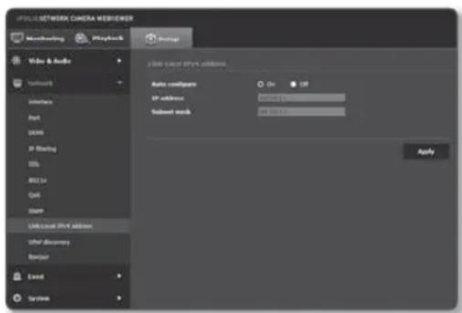
Link-Local IPv4 address
An additional IP address may be assigned to assess the camera from the Link-Local network.
- From the Setup menu, select the
tab. - Click
. -
Set the
. -
Auto configure : It specifies Able or Disable for the Link-Local IPv4 address.
- IP address : Display the assigned IP address.
-
Subnet mask : Display the subnet mask of the assigned IP.
-
When done, click [Apply (Apply)].
text_image
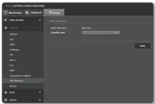
OPULIS NETWORK CAMERA WEB/ENGINEER Monitoring Playback Audio Video & Audio Network Interface Port SOMX IP Starting OSI RISC#L Out Start Unknown IP address other discovery Barrier Event Systems Auto confignet IP address: Subset match: On Off OK OK ApplyUPnP discovery
Cameras can be automatically searched in the client and operating system in support of the UPnP protocol.
- From the Setup menu, select the
tab. - Click
. -
Set the
. -
UPnP discovery : It specifies Able or Disable for UPnP Discovery.
- Friendly name : Display the camera name.
Friendly name is displayed in the format of SAMSUNG-
-- .
In the Windows operating system which basically supports UPnP, the cameras connected to the network are displayed.
text_image
SPEC/METROK CAMERA MODIFIER Monitoring Playback Video & Audio Language Audio Post DONG IP Tracking SSL RISER Out SNPS Link local 3PH address UIFer Modems Balance Event System Audio Modems User Modems Friendly words Apply- When done, click [Apply ( ) Apply
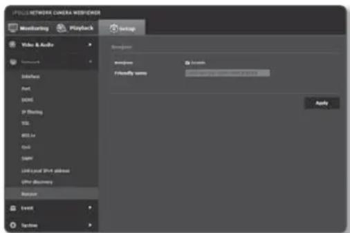
Bonjour
Cameras can be automatically searched in the client and operating system in support of the Bonjour protocol.
- From the Setup menu, select the
tab. - Click
. -
Set the
. -
Bonjour : It specifies Able or Disable for Bonjour.
-
Friendly name : Display the camera name. Friendly name is displayed in the format of SAMSUNG-
- . -
When done, click [Apply (Apply)].
text_image
PNG NETWORK CAMERA WEB/FNDER Monitoring Playback Video & Audio Networks Internet Port BOMC IP Flashing SSL MSL.io Ctrl SAPV LINK-UCAL Push address UP/er discovery Restore Event Systems Settings Wireless Install Friendly words 12.0000000000000000000000000000000000000000000000000000000000000000000000000000000000000000000000000000 ApplyIn the Mac operating system, which support Bonjour by default, the connected cameras are automatically displayed in the Bonjour bookmark of the Safari web browser.
If the Bonjour bookmark is not displayed, check Bookmarks Setup in the "Preference" menu.
FTP / E-mail
You can configure the FTP/E-mail server settings so that you can transfer the images taken with camera to your PC if an event occurs.
-
From the Setup menu, select the
tab. -
Click
. -
Select
or and enter / select a desired value.
- FTP configuration
- Server address : Enter the IP address of the FTP server that you transfer the alarm or event images to.
- ID : Enter the user ID with which you will log in to the FTP server.
- Password : Enter the user account password for logging into the FTP server.
- Upload directory : Specify the FTP path where you will transfer the alarm or event images.
text_image
PULL NETWORK CAMERA MEISPAPER Monitoring Playback Video & Audio Network Event FTP 1-mail Server Event status Main output info System Setup C:\Program\nterms Server address: ID Password Upload directory Port Password mode: OK OR Apply C:\test-compressor Server address: Use authentication: Use URL: OK OR Password Port Recipient Sender Subject Only: Apply- Port : The default port of the FTP server is 21; however, you can use a different port number according to the FTP server settings.
- Passive mode : Select
- E-mail configuration
- Server address : Enter the IP address of the email server that you transfer the alarm or event images to.
- Use authentication : Select whether to use authorization.
- Use SSL : Specify the use of SSL.
- ID : Enter the user ID for logging into the email server.
- Password : Enter the user account password for logging into the email server.
- Port : The default port of the email server is 25; however, you can use a different port number according to the email server settings.
- Recipient : Enter the address of the email recipient.
- Sender : Enter the address of the email sender. If the sender address is incorrect, the email from the sender may be classified as SPAM by the email server and thus may not be sent.
- Subject : Enter a subject for your email.
- Body : Provide the text for the massage. Attach the alarm or event images to the email that you are preparing.
- When done, click [Apply (Apply)].
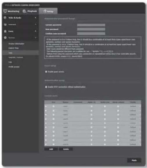
User
-
From the Setup menu, select the <System ( ▶ tab.
-
Click
. -
Provide the necessary user information.
- Administrator password change : Change the password for the administrator.
For the security purposes, you are recommended to use a combination of numbers, alphabets uppercase and lowercase and special characters for your password.
It is recommended to change your password once every three months.
■The password length and limits are shown as follows.
A combination of at least three types of upper case, lower case, numeric, and special characters: 8 to 9 characters.
A combination of at least two types of upper case, lower case, numeric, and special characters: 10 to 15 characters.
Should be different from the ID.
text_image
PROJETO NETWORK CANADA CHECKED Marketing Playback Help Video & Audio Networks Text Search Product information Click Key Help Settings / Options URL Findable access A hierarchical password format: Current password: New password: Confiate new password: If the password is to be any log, then it should be combined of all key types or types of new accounts, contains and contain characters. If the password is to be 1/10/10/10/10, then it should be a combination of all key types or types of new accounts, contains and contain characters. When there would be different from passwords. The following special updates are outlined here: "https://12.1.1.1.1.1.1.1.1.1.1.1.1.1.1.1.1.1.1.1.1.1.1.1.1.1.1.1.1.1.1.1.1.1.1.1.1.1.1.1. View settings: ■ Reach point assets Authentication, access ■ Enable HTTP connection-offline authentication Access (Access) Size Description Access Weighted Allow capacity Allow score Status< > # # # # # # # # # # # # # # # # # # # # # # # # # # # # # # # # # # # # # # # # # # # # # # # # # # N A B C D E F G H I J K L M N O P Q R S T U V W X Y Z
< > < > # # # # # # # # # # # # # # # # # # # # # # # # # # N A B C D E F G H I J K L M N O P Q R S T U V X Y Z
Add Delete Apply-For higher security, you are not recommended to repeat the same characters or consecutive keyboard inputs for your passwords.
Special characters that are allowed.: \~!@#\$%^*()_-+=|{}].?/
- When you access the camera web page for the first time or access it after the initialization, you will be moved to the admin password setting menu.
In this menu, you need to login again with the new password before using the camera web page menus.
-If the existing password is not matched, when you change the admin password, you cannot change the password.
After changing your password, if there is a camera connected to a CMS or NVR client, then you need to re-register it with the newly changed password. If the camera is still connected with the same password, then the account may be locked because a client uses the previous password.
If you try to login with the registered account, 5 or more consecutive password authentication has failed, and then the account may be locked for thirty seconds.
- When the password is changed while multiple connections are active from a PC, the browser may malfunction. In that case, reconnect to the server.
setup screen
- Guest setup : If you select
The ID/password for the guest account is
- Authentication setup : If you select
- Current users: If you select
The administrator can set the audio input, audio output and alarm output permissions.
Profile : If you select
! ONVIF functions available to a registered user allowed to use ONVIF functions are limited to those of granted with permission.
■Video Transfer and Changing Video Information: Set the profile to
■Video Transfer, Changing Video Information, Alarm Output : Set the profile to
4. When done, click [Apply (
Apply
SAMSUNG