Hannibal HSS-3212 D2 - Subwoofer Deaf Bonce - Free user manual and instructions
Find the device manual for free Hannibal HSS-3212 D2 Deaf Bonce in PDF.

User questions about Hannibal HSS-3212 D2 Deaf Bonce
0 question about this device. Answer the ones you know or ask your own.
Ask a new question about this device
Download the instructions for your Subwoofer in PDF format for free! Find your manual Hannibal HSS-3212 D2 - Deaf Bonce and take your electronic device back in hand. On this page are published all the documents necessary for the use of your device. Hannibal HSS-3212 D2 by Deaf Bonce.
USER MANUAL Hannibal HSS-3212 D2 Deaf Bonce
natural_image
Technical line drawing of a mechanical component with concentric rings and mounting holes (no text or symbols)Hannibal SERIES
HSS-2810 D2 HSS
L812 D2 HSS-3212 D2 H
5-3215 D2
CONTENTS
- Introduction
- Safety instructions
- Wiring diagrams
- Recommended enclosure parameters
- How to use
- Specifications
- Dimensions
- Box contents
-
Warranty and maintenance info
-
Information on disposal of the electrical and electronic equipment (for the European countries with separate waste collection)
1. INTRODUCTION
Thank you for purchasing this Deaf Bonce product of Hannibal series! Our company is committed to the creation of extremely loud systems with no loss of quality
To ensure proper use, please carefully read through this manual before using this product. It is especially important that you read and observe caution's in this manual. Please keep the manual in a safe and accessible place for future reference.
2. SAFETY INSTRUCTIONS
- Fasten the subwoofer properly when installing it in the vehicle. If the component is disconnected during driving, it may cause serious damage to the passengers of the vehicle or another vehicle.
- Before installing the components, if possible store the product in its original package to avoid accidental damage to the product.
- Be careful when installing and dismantling the subwoofer! Do not let the subwoofer drop to avoid damage of its moving parts.
- When working with tools follow safety rules.
- Before the installation switch off the head unit and all other audio devices to avoid their damage.
- Make sure that the location of the subwoofer does not hinder the proper operation of mechanical and electrical devices of the vehicle.
- Do not install components in places exposed to water, excessive humidity, high or low temperature, dust or dirt. ATTENTION!!! The product may be operated at +5 °C (41F) to +40 °C (104F). In case of moisture condensation, let the product to dry.
- When performing plumbing, drilling or cutting works with the car, make sure that there is no wiring, brake lines, fuel pipe or other structural elements under the place of work. Follow the safety rules! Use protective glasses and gloves.
- When stretching back the speaker cables make sure that they are not in contact with sharp edges or moving mechanical devices. Make sure that they are firmly fixed and protected over the entire length.
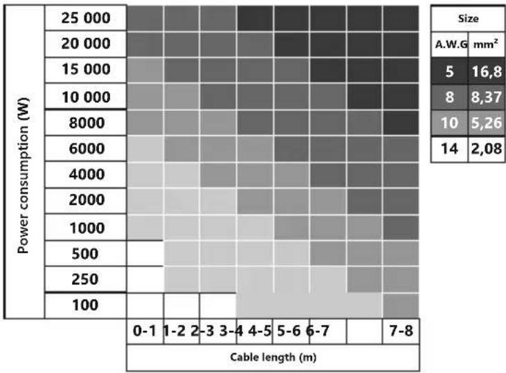
- The diameter of the speaker cables must be selected in accordance with the length and applied power.
- Never stretch the cables outside of the car and near the moving parts of the car. This can lead to destruction of the insulating layer, short circuit and fire.
- To protect the cables use rubber gaskets if the wire passes through a hole in the plate, or other similar materials if it lies close to the parts exposed to heat.
CAUTION!!! High sound pressure can damage your health!
Please use the common sense when controlling volume!
3. WIRING DIAGRAMS
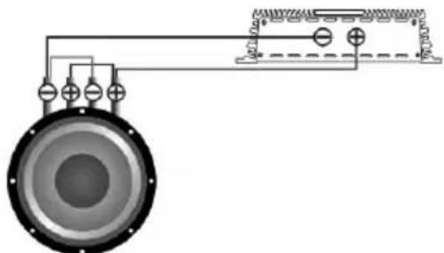
Attention! You need to connect both voice coils of the subwoofer.
Do not expose your amplifier to loads below the value predetermined by the manufacturer.
Various examples of connection types are given at the pages below. Use these examples to determine the required load impedance of your connection.
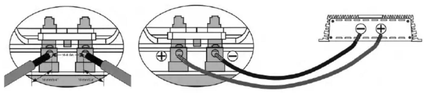
Connection of terminals
Serial connection
Total impedance = ΩSub 1 + ΩSub 2 + ΩSub 3 ...
Parallel connection
EN

Schemes of enabling the load of the subwoofer
In any case do not expose the amplifier to the loads lower than specified by the manufacturer. Use these schematics to calculate load impedance of different connection types.
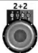
Voice coils 2+2 Ohm
The subwoofer has voice coils D2.
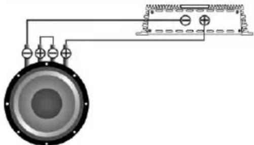
One subwoofer, coils in series
natural_image
Pure electrical circuit lines without any symbols| Voice coils | Total impedance |
| 2+2 Ohm | 4 Ohm |
One subwoofer, coils in parallel
natural_image
Pure electrical circuit lines without any symbols| Voice coils | Total impedance |
| 2+2 Ohm | 1 Ohm |
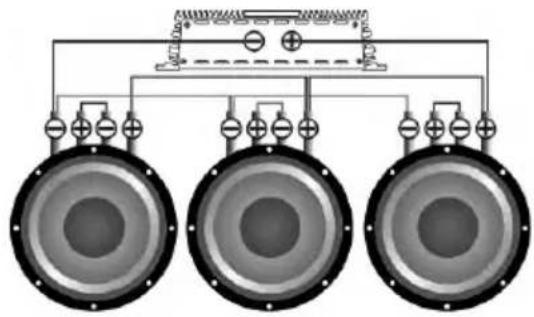
Subwoofers in series, coils in parallel
natural_image
Pure electrical circuit lines without any symbols| Voice coils | Total impedance |
| 2+2 Ohm | 2 Ohm |
| Voice coils | Total impedance |
| 2+2 Ohm | 3 Ohm |
natural_image
Pure electrical circuit lines without any symbols| Voice coils | Total impedance |
| 2+2 Ohm | 4 Ohm |
EN
Subwoofers in series, coils in series
natural_image
Diagram of a dual speakers with speaker holes and wiring connections (no text or labels)| Voice coils | Total impedance |
| 2+2 Ohm | 8 Ohm |
natural_image
Pure electrical circuit lines without any symbols| Voice coils | Total impedance |
| 2+2 Ohm | 12 Ohm |
natural_image
Pure electrical circuit lines without any symbols| Voice coils | Total impedance |
| 2+2 Ohm | 16 Ohm |
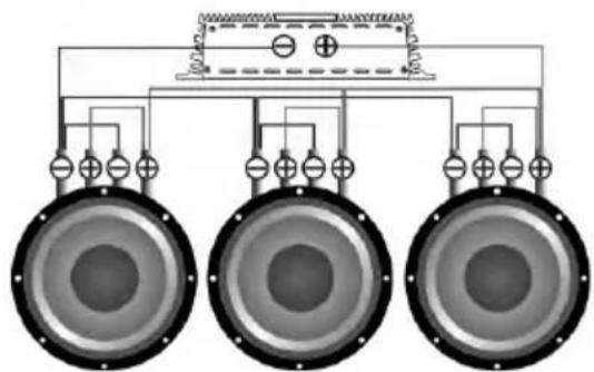
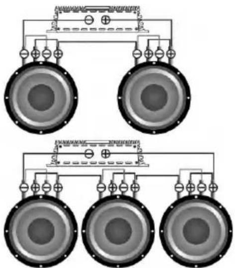
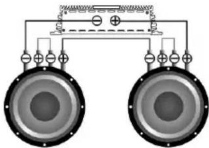
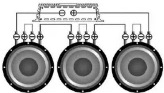
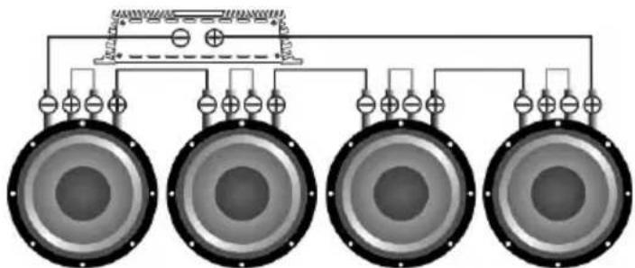
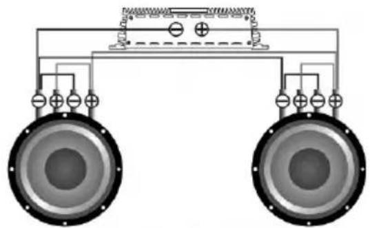
Subwoofers in parallel, coils in series
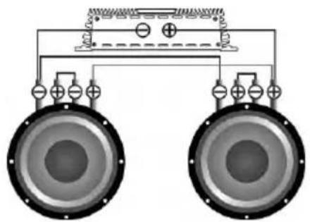
natural_image
Diagram of two speakers with circuit connections and a top-mounted device (no text or symbols)| Voice coils | Total impedance |
| 2+2 Ohm | 2 Ohm |
natural_image
Pure electrical circuit lines without any symbols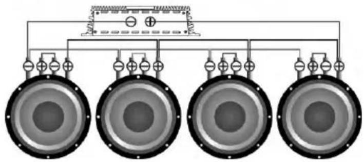
natural_image
Diagram of four speakers arranged in a row connected to a central speaker block (no text or labels)| Voice coils | Total impedance |
| 2+2 Ohm | 1.33 Ohm |
| Voice coils | Total impedance |
| 2+2 Ohm | 1 Ohm |
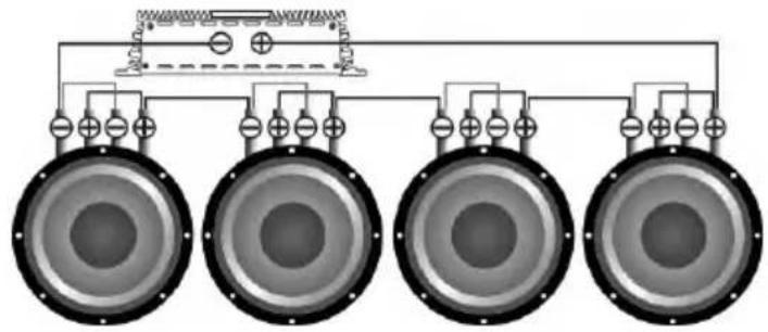
Subwoofers in parallel, coils in parallel
natural_image
Pure electrical circuit lines without any symbols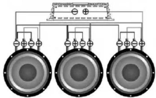
natural_image
Pure electrical circuit lines without any symbols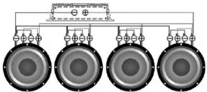
natural_image
Diagram of four speakers arranged in a row with an overhead power supply unit (no text or symbols)| Voice coils | Total impedance |
| 2+2 Ohm | 0.5 Ohm |
| Voice coils | Total impedance |
| 2+2 Ohm | 0.33 Ohm |
| Voice coils | Total impedance |
| 2+2 Ohm | 0.25 Ohm |
CAUTION! High sound pressure can damage your health!
Please use the common sense when controlling volume!
Use the table below to select the desired diameter based on the length and the power consumption.
4. RE COM MEN DED E NCL OSU RE PAR AME TER S
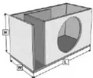
Bass reflex box
natural_image
3D diagram of a rectangular box with an oval recess and labeled dimensions H, W, L (no text or symbols beyond labels)L*W*H = body volume
Parameters/Model
HSS-2810 HSS-2812 HSS-3212 HSS-3215
| The recommended volume, liters / ft3 | 40 / 1.4 | 50 / 1.7 | 50 / 1.7 | 90 / 3.1 |
| Port area, cm2 / inch2 | 80 / 13 | 150 / 24 | 150 / 24 | 200 / 30 |
| Port length, cm / inch | 35 / 13.7 | 62 / 24.4 | 62 / 24.4 | 40 / 15.7 |
Hz setting
37 35 35 35
5. HO W TO US E
The correct choice of the amplifier, its settings and enclosure design prolongs the lifetime of your subwoofer. You should select an amplifier with a nominal power below the nominal power of the subwoofer. Proper coordination of the head unit (HU) with the amplifier will provide a clean, undistorted signal fed to the subwoofer, which prevents overheating and voice coil damage. Like any other speaker the subwoofer has moving and stationary parts. We strongly recommend that the moving parts of the subwoofer should be warmed up at the beginning of operation. Be extra careful when warming up the parts. Warm up the subwoofer using musical material for 40 hours at medium power. If, during operation at maximum volume you feel strange smell, you should lower the volume of the subwoofer and let the device to cool down at a low volume.
Recommended settings of the amplifier and HU: Volume of HU should not exceed 80%. The amplifier sensitivity should be set to 50%, subsonic filter frequency (Subsonic) should be set to 5 Hz below the port settings. For example, if you configure the port at 30 Hz, Subsonic should be set to 25 Hz. The low pass filter LPF (the filter that cuts all frequencies above those set for the filter) should be set to 63-80 Hz, bassboost should be set to 0.
- SPECIFICATIONS
EN
| Model | HSS-2810 HSS-2812 HSS-3212 HSS-3215 | ||
| Size (inch) | 10 12 12 15 | ||
| Surround | Foam Foam Foam Foam | ||
| Cone | Paper Paper Paper Paper | ||
| Frame | Stamped Steel Stamped Steel Stamped Steel Stamped Steel | ||
| Magnet type | Ferrite Ferrite Ferrite Ferrite | ||
| Power RMS (W) | 600 600 1000 1000 | ||
| Power MAX (W) | 1200 1200 2000 2000 | ||
| Voice coil size (inch) | 2.75 2.75 3.15 3.15 | ||
| Voice coil wire | EISV EISV | EISV | EISV |
THIELE-SMALL PARAMETERS
| Impedance (Ohm) | 2+2 | 2+2 | 2+2 | 2+2 |
| Re (Ohm) | 2+2 | 2+2 | 2+2 | 2+2 |
| SPL (dB) | 81.8 83.2 84.5 86.3 | |||
| Xmax (mm) | 11 11 11 11 | |||
| Fs (Hz) | 37.8 35.3 34.5 32.2 | |||
| Vas (L) | 22.35 36.7 41.5 84.1 | |||
| Qts | 0.72 0.89 0.69 0.81 | |||
| BL | 14.2 12.8 17.7 14.7 | |||
This specified sensitivity is not directly connected with the sound pressure in the vehicle and therefore should not be used as the sole indicator for comparison with other subwoofers.
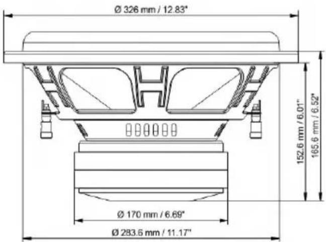
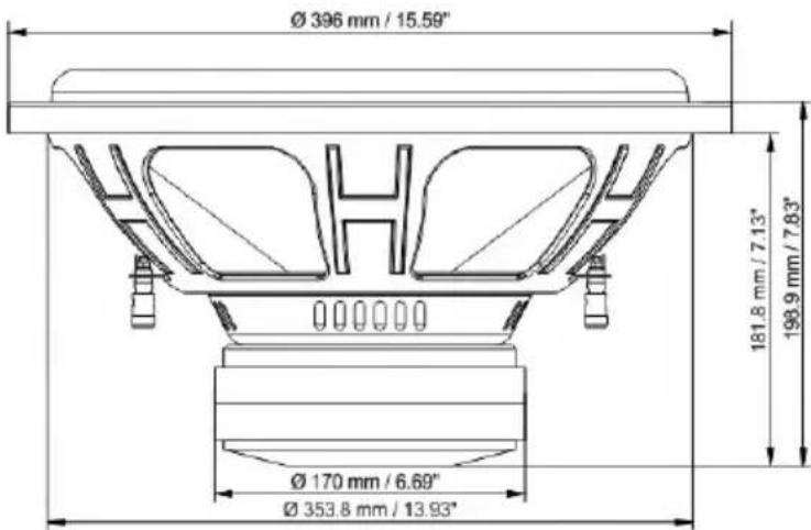
7. DI MEN SIO NS
EN
HSS-2810
HSS-2812
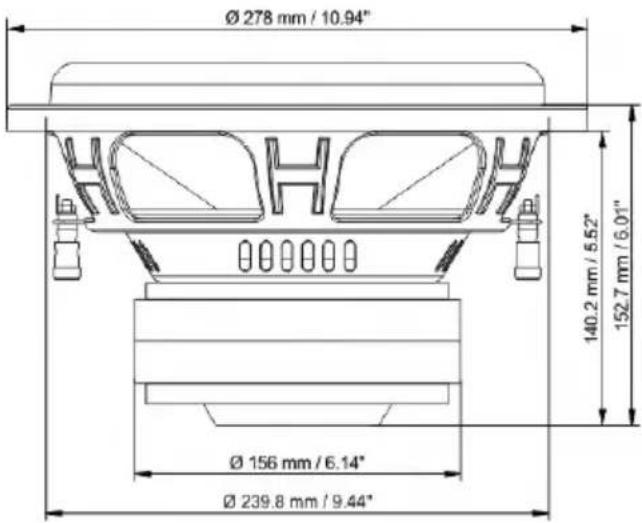
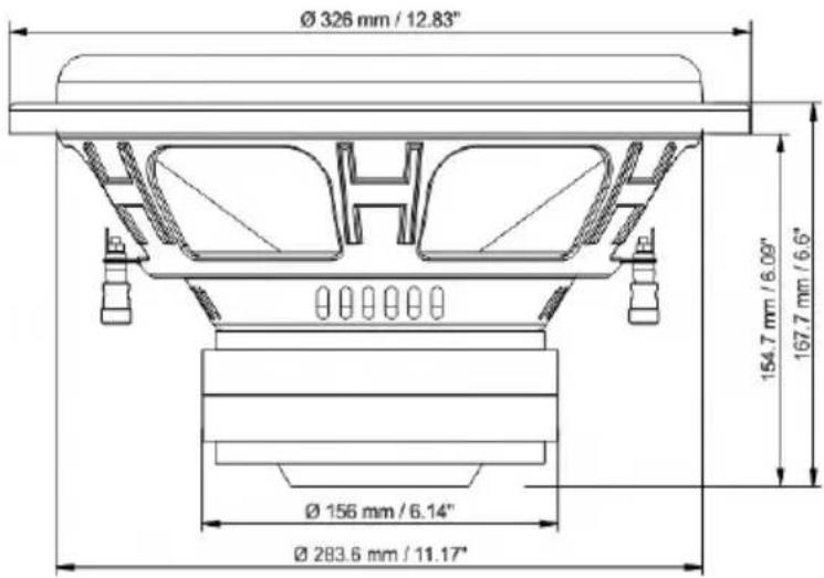
HSS-3212 HSS-3215
8. BOX CON TEN TS
- Subwoofer - 1 pcs.
- Owner's Manual - 1 pcs.
- Warranty card - 1 pcs.
9. WARRANTY AND MAINTENANCE INFO
EN
Deaf Bonce product of Hannibal series are warranted against defects concerning materials and their manufacturing under normal functioning conditions.
While the product is under warranty, defective parts will be repaired or replaced at the manufacturer's discretion. The defective product, along with notification about it, must be returned to the dealer from which it was purchased together with the warranty certificate duly filled in, complete with the original packaging. If the product is no longer under warranty, it will be repaired at the current costs.
Our company does not undertake any liability for damages due to transportation. Our company does not take any responsibility for: costs or loss of profit due to the impossibility to use the product, other accidental or consequential costs, expenses or damages suffered by the customer. Warranty according to laws in force. For more information visit our website and carefully read warranty card. The manufacturer reserves the right to change design and specification without prior notice.
10. INFORMATION ON DISPOSAL OF THE ELECTRICAL AND ELECTRONIC EQUIPMENT (FOR THE EUROPEAN COUNTRIES WITH SEPARATE WASTE COLLECTION)
Items marked "crisscrossed wheeled bin" are not allowed to be disposed of together with usual household waste. These electrical and electronic products should be disposed of in special reception centers, equipped for recycling such products and components. For information about the location of the nearest disposal / recycling spot and the rules of delivery of waste please contact your local municipal office. Recycling and proper disposal helps to protect the environment and prevent harmful effects on health.
Manufacturer: Ningbo Sound Solution I&E Trading Co., Ltd Made in China

dbDRA EMMA european mobile media association
1. ВВЕДЕНИЕ
natural_image
Pure electrical circuit lines without any symbolsnatural_image
Pure electrical circuit lines without any symbolsnatural_image
Pure electrical circuit lines without any symbolsnatural_image
Pure electrical circuit lines without any symbols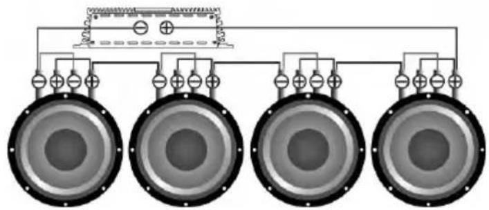
natural_image
Pure electrical circuit lines without any symbolsnatural_image
Pure electrical circuit lines without any symbols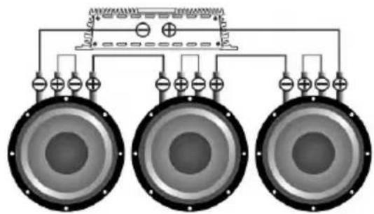
natural_image
Diagram of three speakers connected to a top panel with power lines and grounding symbols (no text or labels)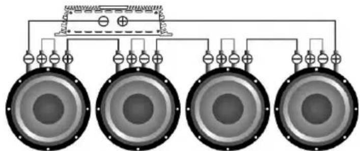
natural_image
Pure electrical circuit lines without any symbolsnatural_image
Pure electrical circuit lines without any symbols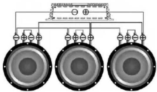
natural_image
Pure electrical circuit lines without any symbols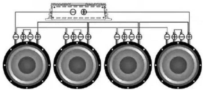
natural_image
Pure electrical circuit lines without any symbolsnatural_image
Pure electrical circuit lines without any symbols