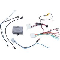
SWRNS-63S - Car audio accessory CRUX - Free user manual and instructions
Find the device manual for free SWRNS-63S CRUX in PDF.


| Product Type | Vehicle Interface Module |
| Brand | CRUX |
| Model | SWRNS-63S |
| Compatible Vehicles | Nissan: 2013-2017 Altima, 2014-2016 Rogue, 2015-2016 Murano, 2017-2018 Sentra, 2014-2019 Versa (select configurations) |
| Key Features Retained | Factory steering wheel controls, Bose amplified system, factory auxiliary input, factory camera (except 360 panoramic), factory USB input, reverse gear output, antenna |
| Included Components | SWRNS-63S module, wiring harness, antenna adapter, SWC cables (3.5mm to 4-pin), USB retention cable, optional accessory power wire |
| Power Input | 12V DC (constant and accessory) |
| DIP Switch Settings | Adjustable for aftermarket radio brands (Alpine, Kenwood, Pioneer, etc.) |
| Installation Type | Wiring harness integration with factory connectors; amplified and non-amplified vehicle diagrams provided |
| Steering Wheel Control | Pre-programmed for Medium Speed CAN-Data Bus; SWC cable options (A for Alpine/Clarion/JVC/Kenwood, B for most others) |
| Antenna Adapter | Included for aftermarket radio antenna connection |
| USB Retention | Included USB retention cable for factory USB port |
| Reverse Gear Output | Provides reverse signal for aftermarket radio |
| Dimensions (Module) | Approximately 2.5 x 1.5 x 0.75 inches |
| Weight | About 0.4 lbs |
| Operating Temperature | -20°C to 70°C |
| Safety Notes | Insulate unused wires; for push-start vehicles use ignition power output (red/black wire); do not cut RCA for amplified systems |
| Warranty | 1 year limited (typical) |
| Repair/Spare Parts | Contact CRUX support for replacement cables or module |
Frequently Asked Questions - SWRNS-63S CRUX
User questions about SWRNS-63S CRUX
0 question about this device. Answer the ones you know or ask your own.
Ask a new question about this device
Download the instructions for your Car audio accessory in PDF format for free! Find your manual SWRNS-63S - CRUX and take your electronic device back in hand. On this page are published all the documents necessary for the use of your device. SWRNS-63S by CRUX.
USER MANUAL SWRNS-63S CRUX
- Retains factory features in select Nissan vehicles while functioning with an aftermarket radio.
- Pre-programmed to retain factory Medium Speed CAN-Data Bus Steering Wheel Controls.
- Includes antenna adapter.
- Retains Bose Amplified system.
- Retains factory auxiliary input
- Retains factory camera (not 360 panoramic camera)
- Retains factory USB input
- Provides Reverse Gear Output
PARTS INCLUDED:
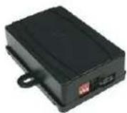
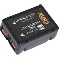
SWRNS-63S MODULE

natural_image
Coiled electrical connectors with various colored wires, no visible text or symbolsSWRNS-63S Harness

Antenna Adapter
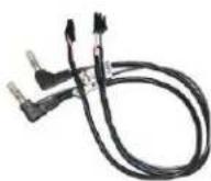
SWC Cables
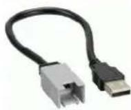
USB Retention Cable

Optional Acc wire
INSTALLATION DIAGRAM FOR AMPLIFIED VEHICLES:

flowchart
graph TD
    A["+12V Constant"] --> B["Yellow"]
    C["+12V ACC"] --> D["Red"]
    E["Ground"] --> F["Black"]
    G["Illumination (+)"] --> H["Orange"]
    I["Illumination (-)"] --> J["Orange/White"]
    K["Amp Turn On"] --> L["Blue/ White"]
    M["Right Front (+)"] --> N["Gray"]
    O["Right Front (-)"] --> P["Gray/Black"]
    Q["Left Front (+)"] --> R["White"]
    S["Left Front (-)"] --> T["White/Black"]
    U["Right Rear (+)"] --> V["Violet"]
    W["Right Rear (-)"] --> X["Violet/Black"]
    Y["Left Rear (+)"] --> Z["Green"]
    AA["Left Rear (-)"] --> AB["Green/Black"]
    AC["VSS (Vehicle Speed Signal)"] --> AD["Brown/White"]
    AE["Reverse Gear Output"] --> AF["Violet/White"]
    AG["Ignition power Output"] --> AH["Red/Black"]
    AI["Chassis Ground"] --> AJ["Black (with Ring Terminal)"]
    AK["32 PIN"] --> AL["12v to 6v Converter"]
    AM["20 PIN"] --> AN["8 PIN"]
    AO["USB-Min2"] --> AP["Blue/ Power Antenna"]
    AQ["Yellow RCA (Retain OE Camera) Rear View Camera Signal"] --> AR["12-Pin Black Connector"]
    AS["Red/White RCA"] --> AT["CRUX"]
    AU["4-Pin Connector"] --> AV["3.5MM SWC CABLES (Option A or B)"]
    AW["To Factory Harness"] --> AX["TO aftermarket radio SWC wire or 3.5mm port"]
    AX --> AY["Cap or insulate if not being used"]
    AX --> AZ["Insulate with tape if not being used"]
    BA["Option A"] --> BB["Blue / YELLOW"]
    BC["Option B"] --> BD["To aftermarket radio SWC wire or 3.5mm port"]
USB Retention Adaptor (included in kit)
- For Amplified Systems Please Do Not Cut RCA to get better audio quality
** Please see page 2 for note
INSTALLATION DIAGRAM FOR NON-AMPLIFIED VEHICLES:

flowchart
graph TD
    A["LED Light"] --> B["Aftermarket Radio"]
    C["Vehicle Programming Section"] --> B
    D["LED Light"] --> E["4-Pin Connector"]
    F["Vehicle Programming Section"] --> E
    G["LED Light"] --> H["3.5MM SWC CABLES (Option A or B)"]
    I["Vehicle Programming Section"] --> H
    J["LED Light"] --> K["4-Pin Connector"]
    L["Vehicle Programming Section"] --> K
    M["LED Light"] --> N["To aftermarket radio SWC wire or 3.5mm port"]
    O["Vehicle Programming Section"] --> N
    P["LED Light"] --> Q["Cap or insulate if not being used"]
    R["Vehicle Programming Section"] --> Q
    S["LED Light"] --> T["Insulate with tape if not being used"]
    U["Vehicle Programming Section"] --> T
    V["LED Light"] --> W["Blue/Yellow"]
    X["Vehicle Programming Section"] --> W
    Y["LED Light"] --> Z["USB/Power Antenna"]
    AA["Vehicle Programming Section"] --> Z
    AB["LED Light"] --> AC["USB Retention Adaptor (included in kit)"]
    AD["Vehicle Programming Section"] --> AC
    AE["LED Light"] --> AF["12-Pin Black Connector"]
    AG["Vehicle Programming Section"] --> AF
    AH["LED Light"] --> AI["Yellow RCA (Retain OE Camera) Rear View Camera Signal"]
    AJ["Vehicle Programming Section"] --> AI
    AK["LED Light"] --> AL["12V to 6V Converter"]
    AM["Vehicle Programming Section"] --> AL
    AN["LED Light"] --> AO["Red/White RCA"]
    AP["VSS (Vehicle Speed Signal)"] --> AQ["32 PIN"]
    AP --> AR["20 PIN"]
    AS["VSS (Vehicle Speed Signal)"] --> AT["8 PIN"]
    AS --> AU["Blue/Power Antenna"]
    AV["VSS (Vehicle Speed Signal)"] --> AW["Green/Black"]
    AV --> AX["Violet/White"]
    AY["VSS (Vehicle Speed Signal)"] --> AZ["Green/Black"]
    BA["VSS (Vehicle Speed Signal)"] --> BB["Brown/White"]
    BC["VSS (Vehicle Speed Signal)"] --> BD["Violet/White"]
    BE["VSS (Vehicle Speed Signal)"] --> BF["Violet/White"]
    BG["VSS (Vehicle Speed Signal)"] --> BH["Violet/White"]
    BI["VSS (Vehicle Speed Signal)"] --> BJ["Violet/White"]
    BK["VSS (Vehicle Speed Signal)"] --> BL["Violet/White"]
    BM["VSS (Vehicle Speed Signal)"] --> BN["Violet/White"]
    BO["VSS (Vehicle Speed Signal)"] --> BP["Violet/White"]
    BZ["VSS (Vehicle Speed Signal)"] --> CA["Violet/White"]
    CB["VSS (Vehicle Speed Signal)"] --> DA["Violet/White"]
    DB["VSS (Vehicle Speed Signal)"] --> DC["Violet/White"]
    DD["VSS (Vehicle Speed Signal)"] --> DP["Violet/White"]
    EQ["VSS (Vehicle Speed Signal)"] --> R["Violet/White"]
    SC["VSS (Vehicle Speed Signal)"] --> T["Violet/White"]
    AU["XVSS (Vehicle Speed Signal)"] --> AU1["Violet/White"]
    AUX["VSS (Vehicle Speed Signal)"] --> AUX["Violet/White"]
    AX["XVSS (Vehicle Speed Signal)"] --> AXX["Violet/White"]
    AYX["XVSS (Vehicle Speed Signal)"] --> AYX1["Violet/White"]
    AZX["XVSS (Vehicle Speed Signal)"] --> AZX1["Violet/White"]
    BAX["XVSS (Vehicle Speed Signal)"] --> BAX1["Violet/White"]
    BBX["XVSS (Vehicle Speed Signal)"] --> BBX1["Violet/White"]
    BCX["XVSS (Vehicle Speed Signal)"] --> BCX1["Violet/White"]
    ADX["XVSS (Vehicle Speed Signal)"] --> ADX1["Violet/White"]
** ACC Power Output Note: For vehicles equipped with intelligent key systems (Push Start Button) +12 V accessory red wire may not activate radio, must use ignition power output (Red/Black wire) instead.
* For Non-Amplified systems please cut RCA, and mate colored wires to the appropriate aftermarket radio speaker wires

DIP SWITCH SETTINGS:
AFTERMARKET RADIO DIP SWITCH SETTINGS:
| RADIO BRAND: | DIP#: | 1 | 2 | 3 |
| Atoto, Dual, Fahrenheit, Jensen, Nakamichi, Pioneer, Power Acoustik, Soundstream | OFF | ON | ON | |
| OFF | ON | ON | ||
| Blaupunkt, Most off-brand Radio | OFF | ON | ON | |
| Alpine | OFF | OFF | OFF | |
| Clarion, Stinger | ON | ON | OFF | |
| Kenwood | ON | ON | ON | |
| JVC | ON | OFF | ON | |
| Boss, Old Sony | ON | OFF | OFF | |
| New Sony (with CarPlay) | OFF | ON | OFF |
SWC MODULE
DIP SWITCH

SWC Troubleshoot option

Located internally Need to take plastic Casing off module
- If Steering Wheel Controls don't work or work properly please switch internal dip switch from 3v3 to 5v as shown in picture above.
NOTE: For Atoto, Blaupunkt, Dual, Farenheit, Nakamichi, Power Acoustik, Soundstream, and most off-brand radios, check the aftermarket radio's manual to see if the SWC buttons need to be programmed.
4-PIN SWC CABLE
Use the proper 3.5MM to 4-Pin SWC cable for the aftermarket radio you are using.
OPTION A is used for ALPINE, CLARION, JVC, and KENWOOD units (Blue/Yellow wire is attached) OPTION B is used for ATOTO, BLAUPUNKT, BOSS, DUAL, FARENHEIT, JENSEN, POWER ACOUSTIK, PIONEER, SONY, SOUNDSTREAM and Most Off-Brand Radios.
NOTE: Cap or insulate the 3.5mm plug or Blue/Yellow wire if not being used.
For aftermarket radios that have wires for SWC connections, cut off the 3.5mm plug on the Crux SWC Cable (option B) and connect the SWC wires as follows:
Note that there are some radios that only have SWC1 and SWC2, in this case "shield" does not need to be connected.

RED to SWC Key 1
WHITE to SWC Key 2
SHIELD to SWC Ground
VEHICLE APPLICATIONS:
Compatible Nissan Vehicles
NISSAN
2013-2017 Altima w/ Bose w/o Nav
2013-2017 Altima w/o Bose w/o Nav
2014-2016 Rogue w/ Bose w/o Nav
2014-2016 Rogue w/o Bose w/o Nav
2015-2016 Murano Base w/ Display audio
2017-2018 Sentra w/o Bose, w/o Nav, & w/o Carplay
2014-2019 Versa w/o Nav
*2017-2018 Sentra Base model use: CRUX SWRNS-63U (Analog SWC)


NOTE: Some SWC functions might not be retained for the following radio series: Planet Audio P9900CPA, Jensen CAR 710, Atoto F7, and similar radios of these brands.

3 of 5
rev.091324
STEERING WHEEL CONTROL TROUBLE SHOOTING:
Note: Identify Alpine SWC learning radios by checking for three SWC cables and a SWC learn menu, instead of a 3.5mm SWC input.
If Interface has one SWR-100 Cable included
If Interface has two SWR Cables included
1 - Find the included SWC adapter cable.
1 - Identify appropriate SWC adapter cable. Do not use cable with Blue / Yellow wire.


2 - Prepare the SWC Cable: Cut the SWC cable. You will find a red wire, a white wire, and a ground (shield) wire inside.

natural_image
Pure electrical circuit lines without any symbols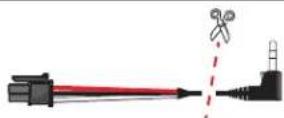
3 - Adjust the Module Settings: Set the module to the Pioneer dip switch setting. This configures the module to communicate correctly with the Alpine radio.
| DIP: | 1 | 2 | 3 | 4 | |
| On Alpine iLX series radios use Pioneer settings | OFF | OFF | ON | ON | |

4 - Configure the Alpine Radio: On your Alpine radio, select the setting that includes an adapter for SWC. This ensures the radio will recognize the steering wheel controls.


Select the setting "With Adapter" Select "SWC Adapter"
5 - Connect the Wires: Connect both the SWC1 and SWC2 wires from aftermarket radio to the red wire from our SWC cable. Connect the SWC ground wire to the shield (ground) wire of our SWC cable. These steps should enable the steering wheel controls on your Alpine iLX series radio.


- Program the SWC: Navigate to the SWC settings on your Alpine radio to assign and test each control function.
ALTERNATIVE ACCESSORY POWER TROUBLE SHOOTING:
Note: If you are experiencing issues with accessory power from the module, you can hardwire it using the extra red accessory wire provided in the kit.

HARNESS VIEW
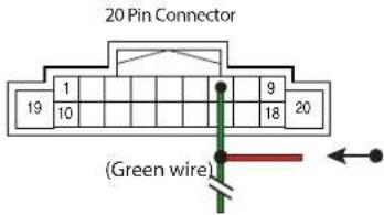
For 2013 NISSAN ROGUE:
Tap the provided red wire to Pin 7 (GREEN) of the 20-pin factory connector.
HARNESS VIEW

For 2014 NISSAN ROGUE
Base w/ Display audio:
If your vehicle has a push start button, tap the provided red wire to Pin 20 (white) of the 24-pin factory connector for accessory power.
If your vehicle uses a regular key, connect the red wire to Pin 7 (light green) of the 20-pin factory connector.
HARNESS VIEW

For 2015 NISSAN MURANO
Base w/ display audio:
If your vehicle uses a regular key, connect the red wire to Pin 7 (pink) of the 20-pin factory connector.
HARNESS VIEW

For 2018 NISSAN SENTRA w/o Bose w/o Nav:
If your vehicle uses a regular key, connect the red wire to Pin 7 (blue) of the 20-pin factory connector.


- DIP SWITCH SETTINGS:
- 4-PIN SWC CABLE
- VEHICLE APPLICATIONS:
- Compatible Nissan Vehicles
- NISSAN
- STEERING WHEEL CONTROL TROUBLE SHOOTING:
- If Interface has one SWR-100 Cable included
- If Interface has two SWR Cables included
- ALTERNATIVE ACCESSORY POWER TROUBLE SHOOTING:
- For 2013 NISSAN ROGUE:
- For 2014 NISSAN ROGUE
- Base w/ Display audio:
- For 2015 NISSAN MURANO
- For 2018 NISSAN SENTRA w/o Bose w/o Nav:
Brand : CRUX
Model : SWRNS-63S
Category : Car audio accessory