NU-RC300 - Uncategorized SHARP - Free user manual and instructions
Find the device manual for free NU-RC300 SHARP in PDF.

User questions about NU-RC300 SHARP
0 question about this device. Answer the ones you know or ask your own.
Ask a new question about this device
Download the instructions for your Uncategorized in PDF format for free! Find your manual NU-RC300 - SHARP and take your electronic device back in hand. On this page are published all the documents necessary for the use of your device. NU-RC300 by SHARP.
USER MANUAL NU-RC300 SHARP
Keep this document for further reference
For Sharp PV Modules
with standard frames 50 mm:
ND-RCxxx
NU-RCxxx
NU-RDxxx
with frames 40 mm:
ND-RJxxx
NU-RJxxx
xxx = Power output in Watt
(250W - 300W)
Version 4 /2016
Table of Content
1 Explanation of safety guidelines......3
1.1 Warnings and notes in this manual ...3
1.2 Notes on modules......3
2 About this manual ....3
2.1 Detailed information for installers and planners....3
3 Handling PV modules....3
3.1 Intended use....3
3.2 Personal protection....3
4 Preparing for installation .... 4
4.1 Handling PV modules....4
4.2 Safety precautions....5
5 Mechanical installation ....6
5.1 Mounting orientation for modules .6
5.2 Safety precautions....6
5.3 Improper mounting 6
5.4 Clearance 6
5.5 Avoiding seals 6
5.6 Clearance under the modules .....7
6 Electrical installation....7
6.1 Connectors 7
6.2 Laying the string cables....7
6.3 Potential equalisation (earthing) of modules frames....8
6.4 Lightning protection 8
6.5 Parallel and serial connection.....8
7 Details of mechanical mouting ..... 8
7.1 Aligning the mounting profiles ..... 8
7.2 Clamp mounting for modules with standard frames....9
7.3 Screw mounting 9
7.4 Insertion mounting 9
7.5 Load levels.... 10
7.6 Mounting drawings for modules. 10
8 For operators : Maintenance ..... 111
8.1 Inspections.... 11
8.2 Review 12
8.3 Details for the inspections...... 12
8.4 Cleaning....12
8.5 Repairs.... 13
9 For operators : Decommissioning .... 13
9.1 Safety precautions 13
9.2 Disposal 13
10 Further information ....13
1 Explanation of safety guidelines

This is the danger symbol. It is used in several versions in this manual to alert you to the potential risk of personal injury.
1.1 Warnings and notes in this manual
The danger warnings are structured as follows: Type and source of danger. Possible consequences of non-observance.
- Measures or prohibitions to avoid the danger.

DANGER!
DANGER indicates an imminently dangerous situation which inevitably leads to death or serious injury if not avoided.
The information on warning and cautions is structured as follows:
Type and source of danger. Possible consequences of non-observance.
- Measures or prohibitions to avoid the danger.

WARNING!
- WARNING indicates a potentially dangerous situation that can lead to death or serious injury if not avoided.

CAUTION!
- CAUTION indicates a potentially dangerous situation that can lead to slight or semi-serious injury if not avoided.
NOTE
NOTE indicates a potentially dangerous situation that can cause material damage if not avoided.
1.2 Notes on modules
The following symbol is attached to the modules:

If this symbol also appears on a danger or warning product label, it is warning you of the danger caused by electric current or voltage that can lead to personal injury if you fail to observe the instructions.
2 About this manual
This installation manual is release version 3.0, dated 07/2016. The publication of this manual renders all previous releases (older than release 3.0) of this manual invalid.
We advise you to use the latest version of the manual at all times.
2.1 Detailed information for installers and planners
2.1.1 Information on the Sharp Web-Site
You can find the latest version of this installation manual and further information on SHARP's web-site : www.sharp.eu
Always use the latest version for your modules if you find a more recent release of the manual.
2.1.2 Information sources for operators
If you have any queries about the latest release, contact your installer or SHARP directly.
3 Handling PV modules
3.1 Intended use
3.1.1 Appropriate use
PV modules are used for generating electrical power in stationary photovoltaic systems which are connected to the grid. If you would like to use the PV modules for another purpose, such as for charging an accumulator directly, you may need additional components (e.g. string diodes). PV modules are suitable for installing near livestock farms and coastal regions.
Observe all the applicable legislation, regulations, guidelines and standards when installing and operating the modules.
3.1.2 Inappropriate use
NOTE
- Do not install PV modules on vehicles and do not use them in air, space or seafaring applications.
- Do not use PV modules if they are exposed to concentrated sunlight or strong artificial light, or if they could be immersed in water or other liquids or exposed to vapour.
3.1.3 Product-specific information
Product-specific information (e.g. the data sheet) contains details of a particular type of PV module.
Only use PV modules for the intended purpose outlined in the product-specific information.
Data sheets may change without prior notice. If the information in the data sheet differs from this manual, the data sheet takes precedence.
3.2 Personal protection
3.2.1 Electrical safety precautions

DANGER!
High DC voltages during storage, installation, operation and maintenance.
Risk of fatal electric shock!
- PV modules may only be installed by qualified technician with a high level of expertise.

DANGER!
Dangerous, high DC voltages generated even at low levels of light, especially in a series connection.
Risk of fatal electric shock!
- Never touch the electrical connections of a PV module under any circumstances, not even if you have disconnected the photovoltaic generator.

DANGER!
Electric arcs form when electrical connections are made or disconnected incorrectly.
Severe or fatal injuries from electric shock or severe injury from burns!
- Before you carry out any work on electrical components, disconnect the photovoltaic generator.

DANGER!
Contact with live parts due to defective insulation or damaged/fallen off junction box covers.
Severe or fatal injuries from electric shock!
- Do not touch damaged parts with your bare hands. - Use protective clothing and suitable, insulated tools.

DANGER!
High DC voltages, even when the photovoltaic generator is disconnected if the generator is earthed.
Severe or fatal injuries from electric shock!
- If the circuit of your photovoltaic generator is earthed, remove the earth before you carry out electrical work on the generator.

WARNING!
Contact with live parts due to unsuitable tools or weather conditions. Risk of electric shock!
- Only use approved, insulated tools for maintenance work on live parts. - Work in dry conditions. Ensure that the electrical connections of the solar module, the cables and the tools, are dry.
RECOMMENDATION
Work in pairs so that in an emergency one person is able to help in the case of injury. This is because the PV modules generate voltage as soon as they are exposed to light. Therefore, parts of the system are nearly always energised during the daytime.
3.2.2 Mechanical safety precautions

WARNING!
Glass can crack, break or splinter. Beware of injury!
- Never step or sit on PV modules. - Avoid knocking and bumping the surface, the edges and corners of the glass panels.

WARNING!
Exposed live parts due to damaged glass. Risk of electric shock!
- Only use PV modules with the insulation in perfect condition.

CAUTION!
Sharp glass edges or flying glass splinters. Beware of injury!
- Always use suitable protective equipment (e.g. gloves and goggles). - Be especially careful with the glass edges and corners of laminates (frameless modules).
• Insulating back sheet

WARNING!
Damaged insulating back sheet. Risk of electric shock and burns!
- Avoid any contact with the back of the module with sharp or pointed objects. - Ensure the back sheet remains undamaged.
4 Preparing for installation
4.1 Handling PV modules
4.1.1 Storing PV modules
■ PV Modules in packing units :
NOTE
- For PV modules packed in vertical position: Store the PV modules upright in the packaging units. Make sure that each module has sufficient support. - For PV modules packed in horizontal position: Store the PV modules flat in the packaging units. - Do not stack the packaging units. This could damage the PV modules.
■ Individual PV modules:
NOTE
- Store individual PV modules in an upright position on wedges with suitable padding. Use adequate padding between the individual PV modules.
- Avoid stacking individual PV modules, as well as the pallets they rest on.
4.1.2 Unpacking PV modules
■ Only for PV modules packed in vertical position
NOTE
- Using an underlay, incline the pallet (e.g. with a beam, height approx. 10 cm for 5^ inclination), so that the opening on the front of the box is elevated. The modules then lean back in the box which makes it easier to remove them.
- Use an underlay for inclining which supports the whole side of the pallet (e.g. a beam). This keeps the modules supported in the box along their entire width.
- Remove the module from this side only. Remove the module with the help of another person, if possible.
- Observe the unpacking instructions on the module box.
4.1.3 Checking PV modules
NOTE
- Before installation, check each PV module for mechanical defects. Pay particular attention to possible damage to glass panels and insulated back sheets.
- In addition, check the insulation on the cables, connectors and junction boxes.
- If you discover any defects, report them to the supplier or transport company immediately.
4.1.4 Transporting PV modules to installation sites
■ All framed modules
NOTE
• Always carry the PV module with one other person. Take hold of the PV module on its long sides.
- When transporting individual PV modules, make sure that you do not put any strain or pressure on the junction box and cables.
4.2 Safety precautions

DANGER!
When installing on roofs or other elevated sites, objects may fall down.
Severe or fatal injuries are possible!
- Block off the danger zone for people and animals before beginning installation work. If possible, remove all objects from the danger zone.

DANGER!
Electric arcs form when electrical connections are made or disconnected incorrectly.
Severe or fatal injuries from electric shock or severe injury from burns!
- Disconnect the photovoltaic generator before you carry out any work on the electrical components of the photovoltaic generator.

DANGER!
High DC voltages, even when the photovoltaic generator is disconnected, if the generator is earthed.
Severe or fatal injuries from electric shock!
- If the circuit of your photovoltaic generator is earthed, remove the earth before carrying out electrical work on the generator.

WARNING!
Exposed live parts on damaged modules. Danger of electric shock!
- Only use components which are in perfect condition for use in photovoltaic systems. Do not install PV modules with visible damage to the glass panels, the insulating back sheet or on the insulation of electrical connections.

WARNING!
Contact with live parts due to unsuitable tools or wet conditions. Danger of electric shock!
- Only use approved, insulated tools for installation or maintenance work on live parts.
- Work in dry conditions. Make sure that the electrical connections on the solar module, the cables used for installation and the tools, are dry.
4.2.1 Health and safety

UTION!
Risk of slipping due to wind, rain, snow or ice. Risk of injury due to falling or colliding with objects!
- Avoid unfavourable weather conditions, such as strong wind or rain.
- Also avoid working on the installation site in ice and snow.
- Use the safety equipment required or recommended by local regulations, such as hard hats, steel-capped shoes with rubber soles, protective goggles, gloves or fall-protection systems.
CAUTION!
Hot module parts in strong sunlight. Risk of burning!
- Protect yourself from burning by wearing gloves and suitable clothing.
5 Mechanical Installation
5.1 Mounting orientation for PV modules
For roof top installations, install the PV modules on fire resistant roofs only. Please note that additional fire proofing might be required, depending on local building / fire codes.
5.1.1 Vertical (portrait) mounting
When mounting the PV module vertically, make sure that the exit holes for the cables on the junction box are facing towards the ground.
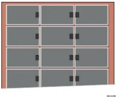
5.1.2 Horizontal (landscape) mounting
When mounting horizontally, make sure that the exit holes for the cables on the junction box are positioned on the inside of the photovoltaic generator. Avoid the lateral outer edges of the photovoltaic generator to minimize the effect of ambient conditions, such as wind or rain
5.1.3 Inclination
Incline the surface of the PV modules at an angle of at least 10^ horizontally, so that precipitation can drain off which supports the modules self-cleaning.
For optimum self-cleaning, we recommend an angle of at least 15^ horizontally.
natural_image
Grid of 12 gray rectangular panels with black square markers, no text or symbols presentFig.1 Recommended position of the junction boxes for horizontal mounting (facing the middle of the generator)
5.2 Safety precautions
NOTE
Do not drill any additional holes in PV modules or their frames.
5.3 Improper mounting
NOTE
- Do not attach the PV modules using nails. The vibration created in the process can cause micro fissures and loss of yield, and results in loss of warranty rights.
- Do not attach the modules by welding. The temperatures created in the process can cause delamination, micro fissures and loss of yield, and results in loss of warranty rights
5.4 Clearance
5.4.1 Clearance between PV modules
NOTE
- Leave a minimum clearance when mounting PV modules.
This prevents mechanical tension due to thermal expansion.
- When mounting at intervals
Leave a clearance of 3 mm or more between the individual PV module frames.
- For edge-to-edge mounting
Allow for an expansion joint of 20 mm after a maximum of 7 m.
- The recommended maximum clearance is 30 cm, based on the PV modules' standard cable length. SHARP recommends mounting at intervals. Also note the information the mounting equipment vendor. This could specify larger intervals
5.4.2 Clearance under the PV modules
■ Minimum clearance
NOTE
• Rooftop or free field mounting
Ensure a clearance of at least 4 cm between the rear edge of the frame and the mounting surface (e.g. the roof tiles) for the rear ventilation of the PV module.
■ Maximum clearance
NOTE
- The largest permissible clearance is defined by national standards. This is used to design the installation on the assumed effects of wind and suction.
- The actual maximum clearance of an installation is determined by the sub-structure. Ensure that your sub-structure adheres to the permissible clearances.
5.5 Avoiding seals
NOTE
- Avoid the use of a seal between PV modules and their mounting surface.
- Dry and cool operation can have a positive effect on the performance as well as the service life of a PV module.
- Also for roof-integrated mounting, ensure good rear ventilation to minimise loss of output which results from a higher module temperature. Ensure adequate ridge ventilation, for example, with a roof ridge ventilator.
5.6 Clearance under the PV modules
NOTE
- Keep the space behind the laminate free of any objects. This prevents damage to the insulating back sheet and the junction box.
- Ensure that sharp or conductive parts (e.g. screws or nails) do not protrude into the space behind the PV module.
- If possible, take measures to prevent foreign objects (e.g. snow, ice, leaves, twigs, branches) from being able to get behind the PV module.
6 Electrical installation
All relevant electrical values are specified on the back-side nameplate of the module.
Under normal conditions, a photovoltaic module is likely to experience conditions that produce more current and/or voltage than reported at standard test conditions. Accordingly, the values of I_sc and V_oc marked on the module should be multiplied by a factor of 1.25 when determining component voltage ratings, conductor current ratings, fuse sizes, and size of controls connected to the PV output.
The modules are qualified for application class A: for the use in systems operating at greater than 50V DC or 240W, where general contact access is anticipated (Modules qualified as application class A in IEC61730 are considered to meet the requirements for Safety Class II. This module is rated as "Fire safety class C" according to IEC 61730.
6.1 Connectors

WARNING!
Incompatible or unsuitable connectors can overheat. Fire hazard!
- Only use connectors that are the same type and from the same manufacturer.
- Avoid using different types of connectors or ones from different manufacturers, even:
- if connecting is possible
- if the connectors have the same basic designation (e.g. "MC4") or
- if they are designated as "compatible".
You can find more details in the next two sections.
6.1.1 PV Module connectors
The various module types can be fitted with the following connectors:
• Original Multicontact® MC4 (with locking)
You can find the specific connectors in the module data sheet.
6.1.2 Connector peculiarities
NOTE
Original Multicontact® MC4-connectors:
- Only plug original Multicontact® MC4 connectors into original MulticontactR®MC4 connectors. ^1
6.1.3 Replacing the connectors
You can remove the connector on a PV module and replace it with another connector, if necessary. You retain the manufacturing warranty if you remove and mount with approved tools in the proper way and according to the connector manufacturer's instructions.
1: The original Multicontact® MC4 connectors are referred to as "MC4" in the data sheet
6.2 Laying the string cables
CAUTION!
Brittle fractures in junction boxes due to contact with unsuitable connection cables: Risk of fire!
- Only use connection cables without plasticisers.
• conductor size: 4mm² type: PV1-F - Ambient temperature: -40^ to 85^
NOTE
Avoid any tensile and pressure loads on the junction box when mounting.
- When mounting, avoid heavy tensile loads on any connectors already plugged in.
NOTE
- Bend the cables from the connector at least 4 cm after they exit from the connector.
- Bend the cables from the junction box as well, at least 4 cm after they exit from the connector.
- This keeps the cables waterproof at the cable outlet.
Observe the guidelines on laying the respective cables. Lay all cables ensuring that:
- You adhere to the minimum bend radius (e.g. 5-fold cable diameter2).
- You avoid laying near sharp corners and edges or protect the cables accordingly.
- cables must not lay between PV module backside and mounting system parts.
- Protect them from direct sunlight and precipitation.
- You secure the cables with UV resistant cable clips or other suitable cable fasteners which protect the cable insulation.
- Cables from PV module strings are laid as near to each other as possible to minimise the effects of being struck by lightning
6.2.1 Weather protection
NOTE
- Lay the cables so that they exit the junction box from below. This prevents water, which runs along the cable, from collecting at the point where the cables exit the junction box.
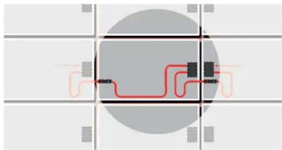
- For PV modules mounted horizontally, lay the cables in a U-form away from the junction box.
- PV modules mounted vertically do not usually need any additional adjustments.
natural_image
Pure electrical circuit lines without any symbolsFig.2 U-form cables at the junction box for a horizontally mounted PV module
Lay cables carefully to protect against damage from:
- Direct environmental factors, such as precipitation
• movement (e.g. from wind)
- Indirect environmental factors, e.g. snow or ice, which slip down behind the modules, and
- Chafing on the insulation due to the cable moving (e.g. from wind or ice)
6.3 Potential equalisation (earthing) of PV module frames
NOTE
- Local regulations may specify potential equalisation (earthing).
- When earthing the PV module frame, establish a safe electrical connection to the earth potential or earthed sub-structure.
- Observe the requirements and recommendations of the inverter manufacturer, as well as insurance policies.
- The PV module frames are made of aluminium. When mounting onto other materials, take suitable measures to prevent electric corrosion, e.g. by using a coating.
NOTE
Potential equalization does not serve as lightning protection. Lightning protection may be necessary in addition to potential equalization.
6.4 Lightning protection

WARNING!
Absence of or inadequate lightning protection. Risk of fire or electric shock!
Leave the planning and installation of the external, and if required internal, lightning protection to be carried out by qualified technicians at all times.
- It is essential to integrate an arrestor for connecting the lightning rod with the lightning protection. This ensures the safety and reliability of the lightning protection as well as the photovoltaic system.
- Do not under any circumstances include the PV module frame or its earth as an active part of the lightning protection (e.g. as a lightning arrestor)
NOTE
If you earth the PV module frame, the only task of this earth is the potential equalisation between the PV module frame and the supporting structure.
6.5 Parallel and serial connection
PV modules of the same type can be connected in parallel. The PV modules in this series are fundamentally designed for series connection.
- Only use PV modules of the same type and output for parallel connection. Take measures for over-current protection (e.g. line fuses) if necessary. Never exceed the specified reverse current loadability of the PV modules. Maximum number of module strings that are allowed to be switched in parallel : 2 (fuse rating / (short-circuit current x1.25)+1)
- Make sure that only PV modules with the same amperage (lmpp) are interconnected for series connection and make sure that the voltages of lines connected in parallel are the same. Even at low temperatures, never exceed the maximum permissible system voltage of the PV modules. Maximum number of PV modules that are allowed to be switched in series; maximum system voltage / (open circuit voltage x 1.25), with respect to the temperature coefficient.
- Make sure that the number and connection of the PV modules match the electrical values specified by the devices connected to the photovoltaic system.
• Make sure that the polarity is correct.
7 Details of mechanical mounting
7.1 Aligning the mounting profiles
7.1.1 Permissible alignment
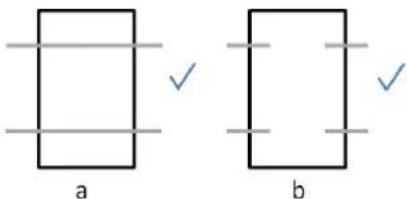
Fig. 3 Permissible alignment of mounting a : Parallel profiles for mounting; b: Parallel, aligned fingers of a mounting system.
7.1.2 Impermissible alignment
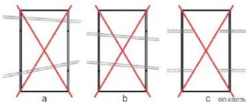
Abb. 4 Impermissible alignment of mounting a: Profiles are not parallel to each other; b: Profiles neither parallel nor perpendicular to the PV module edges; c: The profile ends for the side of a PV module are not connected.
7.2 Clamp mounting for PV modules
7.2.1 Arranging the clamps
■ Permissible arrangement
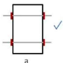
natural_image
Simple geometric diagram with a rectangle and two horizontal lines, one marked with a red plus sign and the other with a blue checkmark (no text or symbols)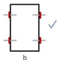
natural_image
Simple geometric diagram of a rectangle with red corner markers and a checkmark (no text or symbols)Fig. 5 Permissible clamp arrangement for framed modules
a, b : Symmetrical clamping on the long side
■ Impermissible alignment
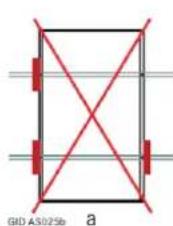
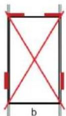
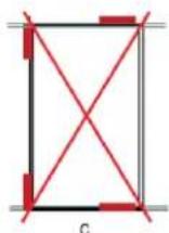
Fig. 6 Impermissible clamp arrangements (1)
a: Missing clamps, b, c: Clamping on both short and long sides.
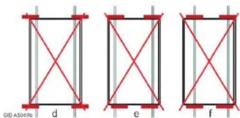
Fig. 7 Impermissible clamp arrangements (2)
d: Protruding clamps, e: Opposing clamps have different distances to the PV module corners,
f: Asymmetrical clamps on the short sides.
7.2.2 Clamp dimensions
Observe the following information for clamp lengths and depths.
■ Clamp lengths and depths
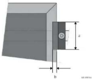
natural_image
Technical diagram of a mechanical component with labeled dimensions (a and b), no readable text or symbols present.Fig. 8 Definition of clamp length and depth for framed PV modules
a: Clamp length, b: Clamp depth.
NOTE
- The required minimum length of a clamp (parallel to the frame side) is 30 mm.
- The required minimum depth of a clamp (perpendicular to the frame side) is 3 mm.
• We recommend a clamp depth of 5 mm. - Depending on the ambient conditions (e.g. angle, suction load or tolerances of the substructure) a higher minimum area per clamp may be required.
- The clamps determine the actual clamp depth and length.
- Observe the instructions of the clamp manufacturer.
7.2.3 Tightening torque for clamp mounting
Tighten the screws on the clamp manually. If you use an automatic screwdriver, then set a suitable maximum tightening torque. You can find details for this in the manufacturer's documentation for the substructure.
7.3 Screw mounting
7.3.1 Only for PV modules with standard frames
The PV modules have a mounting hole with a diameter of 9 mm.
Note : The PV modules with 40mm frames have no mounting holes
7.3.2 Tightening torque for screw mounting
For M8 stainless steel screws, use a maximum torque of 24 Nm.
This applies to unlubricated screws with standard thread and strength class of 8.8 (minimum breaking load 29.2 kN).
7.4 Insertion mounting
Observe the manufacturer's instructions for the mounting system. Use the earthing holes for the potential equalisation.
Although edge-to-edge mounting is possible (see also Ch. 5.4.1: „Intervals between PV modules with standard frames“), we recommend mounting at intervals.
7.5 Load levels
A load can be a pressure load as well as a suction load. Loads from snow and wind need to be taken into account at the installation site.
7.6 Mounting drawings for modules
The maximum permissible load is 2400Pa (for wind and snow) when mounting the modules by using crews, clamps or insertions systems
NOTE
If there is a risk of sliding snow, an appropriate measure has to be taken so that PV module frames on lower edge of PV modules will not be damaged (e.g. by using snow hook).
The PV modules have passed a snow load test in accordance with IEC61215.
7.6.1 Maximum load 2400Pa (wind/ snow)
| Boltinghorizontal / vertical | ClampingLong frame side, horizontal / vertical | In-Lay systemLong frame side, horizontal / vertical | |
| frame thickness: 50 mmLoad 2400Pa | 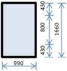 | 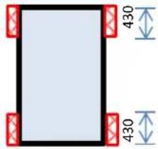 | 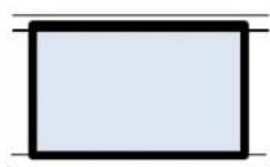 |
| frame thickness: 40 mmLoad 2400Pa | 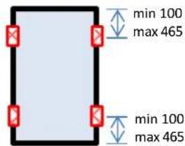 | 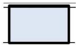 |
Fig. 9a Mounting drawings for load level 2400Pa
All dimensions are shown in mm. Permissible clamping area shown as red crosses.
Note1: Drawings are not always true to scale. The numerical values are binding.
7.6.2 Tested snow load (The modules have passed the test in accordance with IEC61215.)
| Boltinghorizontal / vertical | ClampingLong frame side, horizontal / vertical | In-Lay systemLong frame side, horizontal / vertical | |
| frame thickness: 50 mmTested Load 5400Pa H < 45mm | 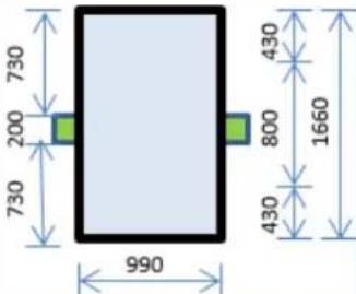 | 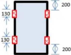 | 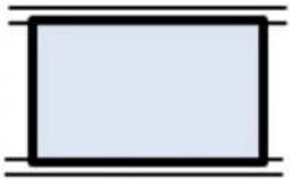 |
| frame thickness: 50 mmTested Load 5400Pa H ≥ 45mm | 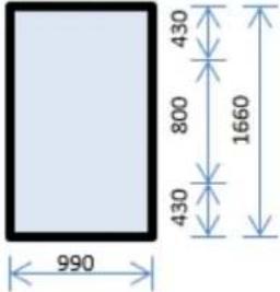 | 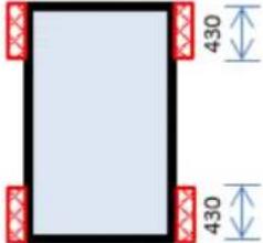 | 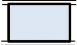 |
| frame thickness: 40 mmTested Load 5400Pa | 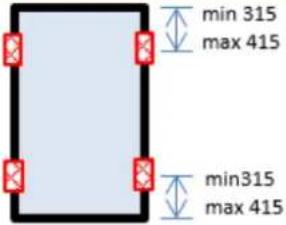 | 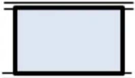 |
Fig. 9b Mounting drawings for tested snow load
All dimensions are shown in mm. H is the clearance between bottom side of the module frame and surface mounting area. Permissible clamping area for the test shown as red crosses.
8 For operators: maintenance
NOTE
Inspect and maintain your system to:
- Keep it safe and reliable
- Achieve top output
- Prevent damage and
- Protect your investment.
It is recommended to carry out regular inspections and to do maintenance so that any problems can be discovered reliably, and rectified.
RECOMMENDATION
- It is recommended to do annual inspections and a more thorough inspection and measurement every 4 years.
- It is also recommended to use a monitoring system to identify any outages or problems quickly.
- Inspecting the output of your photovoltaic system regularly can help to discover problems promptly, and ensures your photovoltaic system operates at top performance, preventing loss of output.
For the proper maintenance and repair of your solar photovoltaic system, contact installer.
8.1 Inspections
An inspection every year is recommended. This should be a visual inspection. Refer to Ch. 8.3: „Details for the inspections“.
The inspection includes the following aspects.
8.1.1 Inspecting the generator
- Strings: condition of the insulation and mounting
• Condition of the junction box
• Condition of the visible connectors
• Condition of the earthing conductors - for direct earthing: connection of the earthing conductors on the frames
- for indirect earthing: connection of the frames to the sub-structure and the earthing conductors to the sub-structure
- Condition of the mounting system (in peripheral area)
- Dirt on modules: type and degree of dirt
- Shade circumstances (e.g. from trees or neighbouring houses)
Clean the components, if necessary.
8.1.2 Inspecting the documentation and drawings
- Checking the PV module string plan 6,
- Check the inverter's status reports
• Determine and archive the annual output - Create and archive the inspection report.
8.2 Review
Carrying out a thorough review at least every 4 years is recommended. This includes the following work in addition to the inspection:
- Measure the characteristics of individual strings (MPP current IMPP, open-circuit voltage UOC, power output PMPP);
• Measure the insulation resistance R_is (7, 8) - Evaluate the annual power output and compare the data with earlier readings;
- Create and archive a review report. Check, repair or replace components, if required.
Refer to Ch. 8.3: „Details for the inspections".
8.3 Details for the inspections
8.3.1 Mechanical inspection
■ Safety precautions
Refer to the notes in Ch. 3.2.2: „Mechanical safety precautions“.
■ Work steps
During the inspection, check that the mechanical connections are clean, securely fitted and properly intact.
8.3.2 Electrical inspection
■ Safety precautions
Make sure you refer to the notes in Ch. 3.2.1: „Electrical safety precautions“.
■ Work steps
During the inspection, check that the electrical connections are clean, securely fitted and properly intact. Identify any defects or irregularities in the electrical installation and make a record of them. Then rectify the problem as quickly as possible.
6 Suggestion for external inspectors: perform a spot check to ensure that the
module string plan matches the installation.
7 According to the standard IEC 61215, a photovoltaic module should have an insulation
resistance of at least 40 Mohm · m².
8 Some inverters provide the measured insulation resistance via an interface.
8.4 Cleaning
Depending on the ambient conditions, PV modules are likely to get soiled more or less heavily over time. This can cause reduced output.
Dirt could be:
- Dust, pollen or seed
- Leaves or twigs
- Deposits from stable vapour
- Moss, algae, fungi or bacteria growing on deposits (in short: biofilms)
- Salt (in coastal regions)
8.4.1 Safety precautions

CAUTION!
Contact of live parts with water. Risk of electric shock!
- Never use a high pressure cleaner.
NOTE
You will also retain the manufacturer's warranty as a result of this measure.
8.4.2 Glass surfaces
NOTE
- The glass surfaces of PV modules have microscopic structures or anti-reflex coatings. Ensure that these do not get damaged. Do not use any cleaning agents which will polish or scratch the surface.
- Avoid the use of very hard water.
- Also avoid the use of distilled or demineralised water if possible.9
- Avoid the use of acids, bases or other aggressive cleaning agents.
NOTE
Dirt- or water-repellent coatings subsequently applied to the modules can negatively affect the efficiency of the PV modules and therefore the power output of the whole photovoltaic system. We therefore advise against the use of these agents.
RECOMMENDATION
For cleaning the glass module surfaces, we recommend :
- Rainwater without additives _10 with its temperature matching the temperature of the module. ^11
• A soft sponge or a soft brush. - If necessary, use a telescopic rod with a sponge or soft brush attached on the end. The rod can have a water pipe integrated.
- For stubborn patches of dirt, use the following to help:
- Isopropanol:
We recommend a mixture of isopropanol and rainwater to the ratio of 1:1.
- Glass cleaner:
As an alternative, we recommend clear, colourless glass cleaner with no ethanol or denaturants (e.g. Bitrex®) _12 .
■ Anti-reflective-Glass
The PV modules have an anti-reflex layer on the glass surface to achieve a higher output. This means that some marks (e.g. fingerprints) are more visible than on normal glass. These marks are mostly seen as shimmering patches. These kinds of marks do not have any measurable effect on the module output and fade away
after about 2 weeks of being exposed to weather conditions, as sunlight and rain break them down.
8.4.3 Insulating back sheet
The insulating back sheet must not be cleaned. Nevertheless, if you still need to perform work behind the modules(e.g. to remove leaves):
- Make sure you refer to Ch. 3.2.1: „Electrical safety precautions“ and Ch. 3.2.2: „Mechanical safety precautions“.
- Avoid damaging the insulating back sheet.
10 Rainwater has a low level of water hardness. It is beneficial to use it because a build up of deposits is avoided.
11 This prevents mechanical tension in the glass and ensures the module a longer service life.
12 Ethanol contains denaturants. Some denaturants can leave streaks behind or damage an anti-reflex layer.
8.4.4 More frequent cleaning
RECOMMENDATION
- In environments subject to heavy soiling, we recommend making the intervals for inspections and cleaning shorter than just once a year.
- For example, this applies to environments with a high exposure to dust, especially close to:
• Large livestock farms - Grain reloading stations
- Green areas with heavy foliage, seeds or pollen
• Factories with high levels of dust emission.
It is recommended to contract a specialised company to clean your photovoltaic generator properly without treading on the modules, if frequent cleaning is necessary.
8.5 Repairs
8.5.1 PV Modules
For repairing PV modules, only use contract technicians who have been authorised by SHARP to avoid loss of warranty. A defective PV module can cause loss of output, as well as consequential damage. If a PV module needs repairing, first get in touch with SHARP (see Ch. 10.2: „Contact“). Never, under any circumstances, repair a PV module by yourself.
Improper repairs can cause damage which may have repercussions years later, such as failure of electrical insulation. This could be fatal. Therefore, report any necessary repairs immediately. Before you carry out any maintenance work on PV modules, deactivate the module string or the whole generator if necessary.
Observe the warnings and notes in Ch. 3.2.1: „Mechanical safety precautions“ and Ch. 3.2.2: „Electrical safety precautions“.
8.5.2 System parts
For repairing other system parts (e.g. substructure, connection boxes), contract authorised technicians to do the work.
9 For operators: decommissioning
9.1 Safety precautions
Make sure you refer to the notes in Ch. 3.2.1: „Electrical safety precautions“. If you would like to continue using the PV module, also refer to Ch. 4.1: „Handling PV modules“
9.2 Disposal
natural_image
Symbol of a trash bin crossed with diagonal lines, no text or labels presentNOTE
- Dispose of the PV modules at the end of their service life in the proper manner.
• To do this, contact a disposal company. - Never dispose PV modules with household waste.
10 Further Information
Further information are available at SHARP's website
10.1 Contact
Sharp Energy Solutions Europe
A Division of Sharp Electronics GmbH
Nagelsweg 33 - 35
20097 Hamburg
Deutschland
Tel: +49 (0)40 / 23 76-24 36
Fax +49 (0)40 / 23 76-15 24 36
SolarInfo.Europe@sharp.eu
www.sharp.eu
10.2 Copyright
This installation manual is protected by copyright. All rights reserved. Copying, reproduction, translation, or conversion to any type of electronic media or machine readable form, in its entirety or parts, is not permitted. An exception will be made for a backup copy for your own use. SHARP reserves the right to change this document without prior notice.