
PLAS 640 - Hob CANDY - Free user manual and instructions
Find the device manual for free PLAS 640 CANDY in PDF.
| Brand | CANDY |
| Model | PLAS 640 |
| Product type | Gas / mixed hob |
| Number of gas burners | 4 (depending on version) |
| Number of electric hotplates | 0 or 1 (depending on version) |
| Surface material | Enameled steel, stainless steel, cast iron, glass or vitroceramic (depending on version) |
| Appliance dimensions (W x D) | 590 x 510 mm (steel/stainless version) or other depending on version |
| Cut-out dimensions (A x B) | 560 x 480 mm (for most versions) |
| Power supply | 230 V / 50 Hz |
| Max installed electric power | 2000 W (if electric hotplate present) or 3500 W (for some versions) |
| Installed gas power (G20) | 7.15 to 9.95 kW depending on version |
| Compatible gas type | Natural gas G20, butane G30, propane G31 |
| Ignition | Integrated electronic or manual |
| Safety | Thermocouple on each burner, automatic shut-off in case of flame failure |
| Residual heat indicator | On vitroceramic versions |
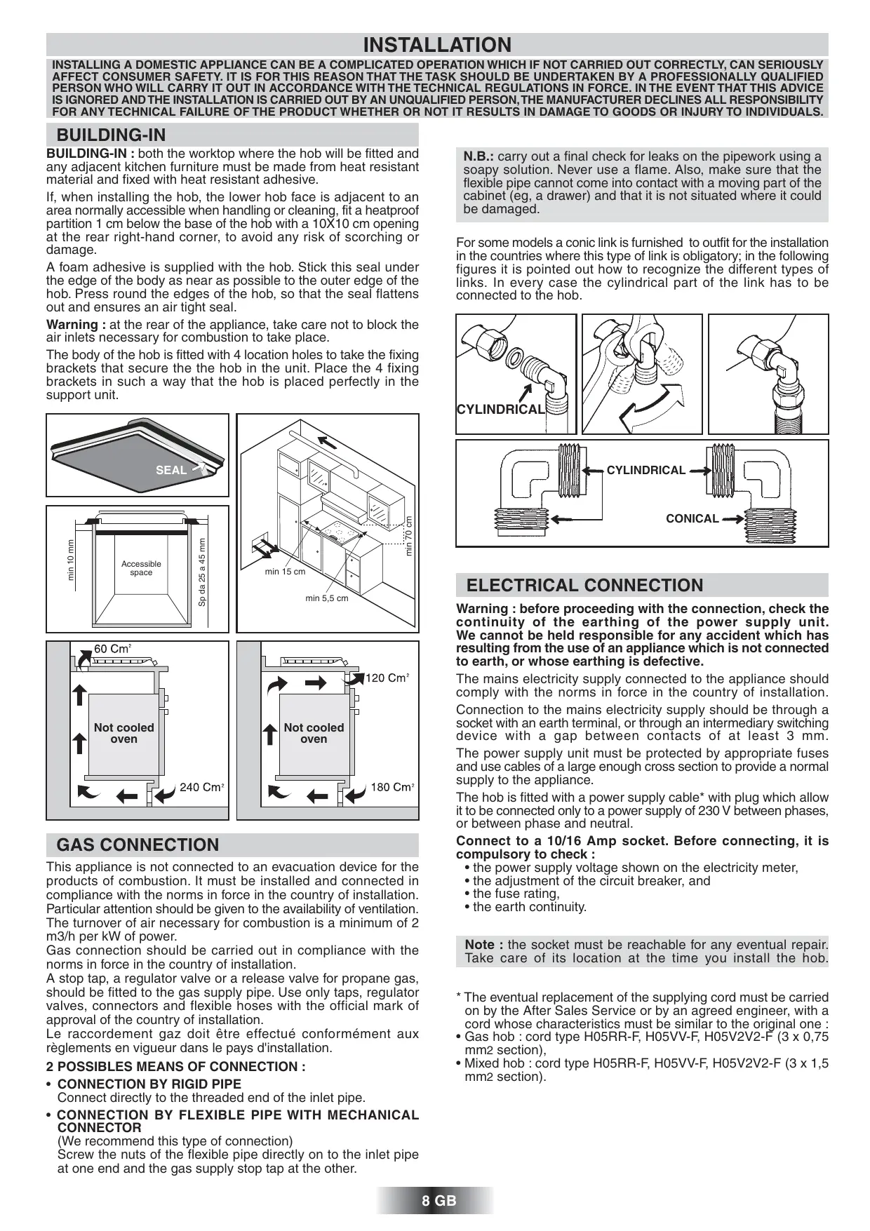
| Electric hotplates | Rapid hotplate with internal thermostat or High Light hotplate on vitroceramic |
| Routine maintenance | Clean with soapy water, avoid abrasives |
| Burner maintenance | Remove cap and body, clean with damp sponge |
| Electric hotplate maintenance | Heat empty then wipe, use renovator product if rust |
| Spare parts available | Injectors, grates, burner caps, etc. on request |
| Repairability | Technical after-sales support, installation by a professional recommended |
| General information | Made in France, compliant with EEC directives |
Frequently Asked Questions - PLAS 640 CANDY
User questions about PLAS 640 CANDY
0 question about this device. Answer the ones you know or ask your own.
Ask a new question about this device
Download the instructions for your Hob in PDF format for free! Find your manual PLAS 640 - CANDY and take your electronic device back in hand. On this page are published all the documents necessary for the use of your device. PLAS 640 by CANDY.
USER MANUAL PLAS 640 CANDY
natural_image
Illustration of two identical electric cooktops with four circular cutouts, shown from different angles (no text or symbols)INSTRUCTIONS GENERALES
LIRE ATTENTIVEMENT LA NOTICE POUR VOUS PERMETTRE DE TIRER LE MEILLEUR PARTI DE VOTRE APPAREIL.
natural_image
Diagram of a rope knot being lifted by a hook, showing rotational motion (no text or symbols)
natural_image
Technical line drawing of a mechanical joint or connector (no text or symbols)
LE RACCORDEMENT ELECTRIQUE
natural_image
Mechanical assembly diagram showing gears and shafts in a circular frame (no text or labels)natural_image
Mechanical assembly diagram showing gears and shafts in a circular frame (no text or labels)LES BRÛLEURS GAZ
TO GET THE BEST FROM YOUR APPLIANCE, PLEASE READ THE FOLLOWING CAREFULLY.
Please keep the operating and installation instructions in a safe place for future reference. Before fixing the hob, note the serial number of the appliance just in case you should require future repairs from our after sales service organisation at some time in the future.
- All accessible parts of the hob will become hot while in operation. Always keep children away from it.
- The hob should be given a quick clean after each use, to avoid the accumulation of spillages and grease. If spillages are not removed, they will harden, and could cause the production of smoke and unpleasant smells.
- When cooking with fats or oils, never leave gas burner unattended. Overheated fats or oils can quickly catch fire.

Rating plate (located under the lower casing of the hob)
In order to improve the quality of the products, the manufacturer may carry out modifications linked to technical improvements.

Appliance meeting with the standard CEE 89/336, 89/109, 73/23 et 90/396.
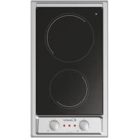
| COOKING HOBS | STAINLESS STEEL / ENAMELLED STEEL HOBS | |||
| Burners | 3 gas1 electric | 4 gas- | 3 gas1electric | 4 gas- |
| Supply Voltage (V/Hz) | 230/50 | 230/50 | 230/50 | 230/50 |
| Installed elettric power (W) | 2000 | - | 2000 | - |
| Power of gas installed: | ||||
| • G20/20 mbar (kW)** | 7,45 | 9,95 | 7,15 | 8,6 |
| • G30/28-30 mbar (g/h) | 543 | 725 | 521 | 627 |
| Product size (l x p) mm. | 590x510 | 590x510 | 590x510 | 590x510 |
| Building - in dimensions (AxB) | 560x480 | 560x480 | 560x480 | 560x480 |
 | ||||
** Manufacturer setting
IE cat. II2H3+
GB cat. Il2H3+
| COOKING HOBS | CAST IRON HOB | GLASS / VITROCERAMIC HOB | |||
| Burners | 2 gas | 2 gas | 4 gas | 3 gas | 3 gas |
| - | 2 electrics | - | 1 electric | 1 electric | |
| Supply Voltage (V/Hz) | 230/50 | 230/50 | 230/50 | 230/50 | 230/50 |
| Installed elettric power (W) | - | 3500 | - | 1800 | 1500 |
| Power of gas installed: | |||||
| • G20/20 mbar (kW)** | 4,65 | 4,65 | 9,5 | 6,5 | 7,75 |
| • G30/28-30 mbar (g/h) | 341 | 341 | - | - | - |
| Product size (l x p) mm. | 330x510 | 596x510 | 600x530 | 600x510 | 600x530 |
| Building - in dimensions (AxB) | 310x490 | 560x490 | 560x480 | 560x480 | 560x480 |
 |  |  |  |  |  |
** Manufacturer setting
IE cat. II2H3+
GB cat. Il2H3+
INSTALLATION
INSTALLING A DOMESTIC APPLIANCE CAN BE A COMPLICATED OPERATION WHICH IF NOT CARRIED OUT CORRECTLY, CAN SERIOUSLY AFFECT CONSUMER SAFETY. IT IS FOR THIS REASON THAT THE TASK SHOULD BE UNDERTAKEN BY A PROFESSIONALLY QUALIFIED PERSON WHO WILL CARRY IT OUT IN ACCORDANCE WITH THE TECHNICAL REGULATIONS IN FORCE. IN THE EVENT THAT THIS ADVICE IS IGNORED AND THE INSTALLATION IS CARRIED OUT BY AN UNQUALIFIED PERSON, THE MANUFACTURER DECLINES ALL RESPONSIBILITY FOR ANY TECHNICAL FAILURE OF THE PRODUCT WHETHER OR NOT IT RESULTS IN DAMAGE TO GOODS OR INJURY TO INDIVIDUALS.
BUILDING-IN
BUILDING-IN : both the worktop where the hob will be fitted and any adjacent kitchen furniture must be made from heat resistant material and fixed with heat resistant adhesive.
If, when installing the hob, the lower hob face is adjacent to an area normally accessible when handling or cleaning, fit a heatproof partition 1 cm below the base of the hob with a 10×10 cm opening at the rear right-hand corner, to avoid any risk of scorching or damage.
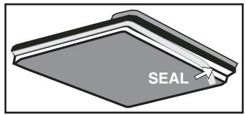
A foam adhesive is supplied with the hob. Stick this seal under the edge of the body as near as possible to the outer edge of the hob. Press round the edges of the hob, so that the seal flattens out and ensures an air tight seal.
Warning : at the rear of the appliance, take care not to block the air inlets necessary for combustion to take place.
The body of the hob is fitted with 4 location holes to take the fixing brackets that secure the the hob in the unit. Place the 4 fixing brackets in such a way that the hob is placed perfectly in the support unit.

GAS CONNECTION
This appliance is not connected to an evacuation device for the products of combustion. It must be installed and connected in compliance with the norms in force in the country of installation. Particular attention should be given to the availability of ventilation. The turnover of air necessary for combustion is a minimum of 2 m3/h per kW of power.
Gas connection should be carried out in compliance with the norms in force in the country of installation.
A stop tap, a regulator valve or a release valve for propane gas, should be fitted to the gas supply pipe. Use only taps, regulator valves, connectors and flexible hoses with the official mark of approval of the country of installation.
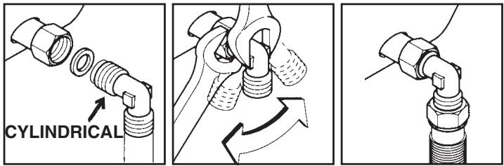
Connect directly to the threaded end of the inlet pipe.
- CONNECTION BY FLEXIBLE PIPE WITH MECHANICAL CONNECTOR
(We recommend this type of connection)
Screw the nuts of the flexible pipe directly on to the inlet pipe at one end and the gas supply stop tap at the other.
N.B.: carry out a final check for leaks on the pipework using a soapy solution. Never use a flame. Also, make sure that the flexible pipe cannot come into contact with a moving part of the cabinet (eg, a drawer) and that it is not situated where it could be damaged.
For some models a conic link is furnished to outfit for the installation in the countries where this type of link is obligatory; in the following figures it is pointed out how to recognize the different types of links. In every case the cylindrical part of the link has to be connected to the hob.

ELECTRICAL CONNECTION
Warning : before proceeding with the connection, check the continuity of the earthing of the power supply unit. We cannot be held responsible for any accident which has resulting from the use of an appliance which is not connected to earth, or whose earthing is defective.
The mains electricity supply connected to the appliance should comply with the norms in force in the country of installation. Connection to the mains electricity supply should be through a socket with an earth terminal, or through an intermediary switching device with a gap between contacts of at least 3 mm. The power supply unit must be protected by appropriate fuses and use cables of a large enough cross section to provide a normal supply to the appliance.
The hob is fitted with a power supply cable* with plug which allow it to be connected only to a power supply of 230 V between phases, or between phase and neutral.
Connect to a 10/16 Amp socket. Before connecting, it is compulsory to check :
- the power supply voltage shown on the electricity meter,
- the adjustment of the circuit breaker, and
- the fuse rating,
- the earth continuity.
Note : the socket must be reachable for any eventual repair. Take care of its location at the time you install the hob.
* The eventual replacement of the supplying cord must be carried on by the After Sales Service or by an agreed engineer, with a cord whose characteristics must be similar to the original one :
- Gas hob : cord type H05RR-F, H05VV-F, H05V2V2-F (3 x 0,75 mm2 section),
- Mixed hob : cord type H05RR-F, H05VV-F, H05V2V2-F (3 x 1,5 mm2 section).
The appliances are regulated by the manufacturer for the type of gas indicated on the packing and on the label attached to the appliance itself. If they are to be used with another type of gas, the appliance must be adjusted in the following way:
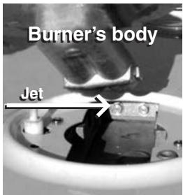
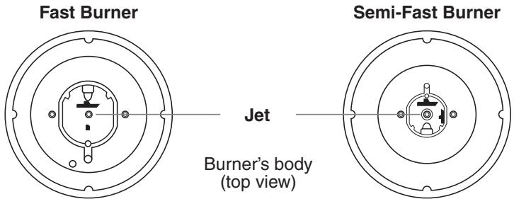
• CHANGING THE JETS
Each jet is designated by size.
To gain access to the jets :
- remove the pan supports,
- remove the burner cap and body,
• using the spanner supplied with the appliance, unscrew the jet,
- fit the correct jet for the type of gas to be used,
- secure the jet tightly,
• regulate the air ring.
- replace the burner body, cap and the pan support.
Example: Ultra-Fast burner
JETS
| Burner | Natural Gas G20-20 mbar G25-25 mbar | Butane Gas G30 28-30 mbar | Propane Gas G31 37 mbar |
| DC/UR (3,2 kW) | 94x2 | 65x2 | 65x2 |
| UR (3,5 kW) | 102x2 | 68x2 | 68x2 |
| R (2,5 kW) | 122 | 80 | 80 |
| SR (1,45 kW) | 96 | 61 | 61 |
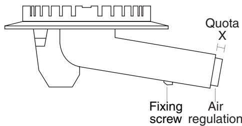
• REGULATE THE AIR RING
Regulating the air ring is important as it ensures the correct combustion and enables the burners to work at maximum efficiency.
It may be necessary to adjust this regulation according to the conditions of your domestic gas supply.
The burner flame should be steady and with no red or yellow points.
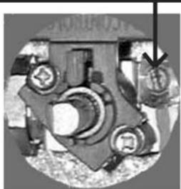
The air ring is located at the lengthening of the burner unit which is fixed by a screw (see drawing).
If necessary :
- unscrew the screw that holds the air flow adjuster,
- set the correct distance according to the air adjuster protrudes,
- secure the screw when the operation is completed.
REGULATE THE AIR RING Quota X in mm
| Burner | Natural Gas G20-20 mbar G25-25 mbar | Butane Gas G30 28-30 mbar | Propane Gas G31 37 mbar |
| UR (3,2 kW) Cast iron hob | 13 | 0 | 13 |
| UR (3,5 kW-3,2kW) | 14 | 0 | 14 |
| R (2,5 kW) | 10 | 0 | 9 |
| SR (1,45 kW) Cast iron hob | 11 | 3 | 11 |
| SR (1,45 kW) | 6 | 0 | 7 |
| DC (3,2 kW) | 15 | 0 | 15 |
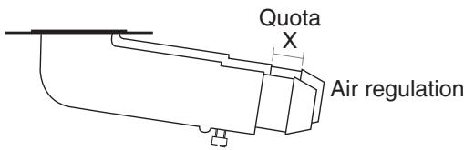
Fixing screw
• REGULATE THE FLAME
If you have changed the type of gas, it is important to verify the flame stability at the minimum regulation.
To gain access to hob burner by-pass screws, remove the knobs from the control panel.
a) Natural gas :
- simply loosen the screw.
- switch on the burner and turn the knob to minimum.
- Turn the by-pass screw ⬇ until a low flame is visible. Turn the control knob from minimum to maximum position to check that it is satisfactory.
b) Butane-propane gas :
The by-pass screw should be screwed fully home, without being locked.
By-pass screw for the hob burner

Never loosen
other screws!
natural_image
Top-down view of a mechanical assembly with gears and levers (no visible text or symbols)The appliances are regulated by the manufacturer for the type of gas indicated on the packing and on the label attached to the appliance itself. If they are to be used with another type of gas, the appliance must be adjusted in the following way:
1
• CHANGING THE JETS
Each jet is designated by size.
To gain access to the jets :
- remove the pan supports,
- remove the burner cap and body,
• using a pipe spanner, unscrew the jet, - fit the correct jet for the type of gas to be used,
- secure the jet tightly,
• regulate the air ring, - replace the burner body, cap and the pan support.
| JETS | |||
| Burner | Natural Gas G20-20 mbar G25-25 mbar | Butane Gas G30 28-30 mbar | Propane Gas G31 37 mbar |
| R (3 kW) | 130 | 86 | 86 |
| SR (1,75 kW) | 100 | 67 | 67 |
• REGULATE THE FLAME
If you have changed the type of gas, it is important to verify the flame stability at the minimum regulation.
To gain access to hob burner by-pass screws, remove the knobs from the control panel.
2
a) Natural gas :
- simply loosen the screw.
- switch on the burner and turn the knob to minimum.
- Turn the by-pass screw ⏻ until a low flame is visible. Turn the control knob from minimum to maximum position to check that it is satisfactory.
b) Butane-propane gas :
The by-pass screw should be screwed fully home, without being locked.
By-pass screw for the hob burner

Never loosen
other screws!

natural_image
Mechanical assembly diagram showing gears and shafts in a circular frame (no text or labels)GAS BURNERS
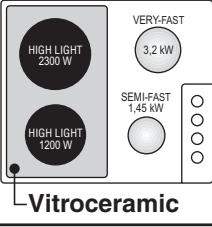
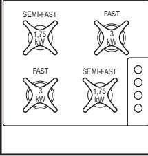
Each burner is controlled by a tap with progressive settings allowing:
* a wider choice of settings from the maximum position to the lowest and most precise one,
* easier flame regulation according to the pan diameter,
* no risk of cutting off the flame or switching off when the flame is turned down quickly.
IGNITION
RECOMMENDATIONS : when the burners are not in service, the general gas supply tap should always be turned off.
- Turn on the gas tap,
- A symbol next to each control knob indicates which burner is lit.
- Turn and press in the relevant burner control knob to the “+” (💧) symbol, keeping it pressed in until the flame ignites. On models fitted with electronic ignition the flame is ignited by an electric spark. This is operated by the button or by pressing the knob (for models with ignition under the knob).
For models not fitted with electronic ignition, or if there is no electric power, light the flame with a match.
NB: for models fitted with the SAFETY thermocouple, keep the knob pressed in for a few seconds in order to activate the safety system. If the knob is released straightaway there is not time for the safety system to be activated and the flame goes out. If this happens, repeat the ignition procedure from the beginning waiting longer after the flame is lit.
The rapid thermocouple safety device automatically cuts off the gas supply if the flame is accidentally extinguished.
If there are particular local gas supply conditions which make ignition difficult, you are advised to repeat the ignition procedure, turning the knob to “minimum” (💡).
- Set the flame according to your cooking requirements. Intermediate positions are available between the "+" (💧) and "-" (💧) settings on the control knob.
- To turn the flame out, turn the control knob back to stop position.
- If the burner is accidentally extinguished, turn the knob to "0", wait one minute and then try to ignite again.
PANS
For a proper use of the burners, choose pans which match the dimensions given below :
* Double ring ∅ 18 cm and more
* Very fast ∅ 18 cm and more
* Fast ∅ from 16 to 18 cm
* Semi-fast ∅ 12 cm
- Pans with curved, ridged or warped bottoms are not recommended.
- Aluminium pans may leave marks on the enamelled pan support. These marks can easily be removed with a damp cloth and a light abrasive product.
SOME TIPS ....
- Avoid boiling food too intensely. Food is not cooked any more quickly this way. In fact,
it is subjected to severe agitation, which may cause the food to lose some of its flavour. - To save gas, make sure that the flames do not overlap the bottom of the pan.
- Do not use the gas burner with an empty pan.
THE ELECTRICAL HOT-PLATE
THE ELECTRIC HOTPLATE:

the power is controlled by the position of the knob (see table below).
The electric hotplates with a red dot in the middle is with automatic protection; there is an internal these hotplates which automatically reduces the abnormal temperature is detected (for example, g empty).
THE HIGHLIGHT HOTPLATE: used with glass/ceramic products; it has a metallic laminate which spreads the heat uniformly over the whole area. It heats up in three seconds and allows even and delicate cooking as well as high temperature cooking; power is regulated by the position of the knob (see table below).
BEFORE USING THE ELECTRICAL HOT PLATE :
- Before using the electric hot plate for the first time, let it heat up for a few minutes, without a pan, at maximum temperature to allow the protective coating to harden.
HOW TO USE :
- For best results, it is advisable to start on the maximum heat and then turn back to an intermediate temperature taking into account the type and volume of the food.
- An indicator light comes on to show that the hot plate is operating.
- To switch off, turn the knob back to point "0".
DIFFERENT TEMPERATURE SETTINGS :
Below are a few examples which are given as guidelines. When you become more familiar with the appliance, you will be able to choose settings to suit your own personal tastes and requirements.
The residual heat indicator lights up when the hilight zone temperature is 60^ C and above. It will stay on, even if the zone is switched off, until the surface has cooled down. It will switch off when the temperature of the surface falls below 60^ C.
| Positions | Some Tips | ||
| 1 | 1-2 | Very Low | To keep a dish hot, melt butter and chocolate... |
| 2 | 3-4 | Low | Slow cooking, sauces, stews, rice pudding poached eggs... |
| 3 | 5-6 | Moderate | Beans, frozen foods, fruit, boiling water... |
| 4 | 7-8 | Medium | Steamed apples, fresh vegetables, pasta, crepes, fish... |
| 5 | 9-10 | High | More intense cooking, omelettes, steaks... |
| 6 | 11-12 | Very High | Steaks, chops, frying... |
SOME TIPS ....
To get the best results from your appliance it is important to observe the following :
- Use thick, flat-based cooking vessel :
a completely flat base prevents overheating to certain parts which causes food to stick. Thick metal allows for good heat distribution. - Make sure that the base of the pan is dry :
this will prevent sticking to the hot plate caused by moisture. - Use pans with a diameter large enough to completely cover the hot plate,
otherwise energy will be wasted and any spillages will cause the hot plate to become stained and will become difficult to maintain (rust, etc.). - Never leave a hot plate switched on without a pan on it: it can be damaged, which would reduce its efficiency.
- When cooking with fat or oil, never leave the hob unattented, very hot fats and oils can quickly catch fire.
- When the hot plate is hot, avoid any contact with materials made of plastic or aluminium foil.
Caution :
the heating surfaces clearly get hot while operating, so make sure that small children are kept well away from the hob.
CLEANING
Before cleaning or removing the hob, it is imperative to :
- disconnect the hob from the mains supply,
- let all parts of the hob cool down.
Never use :
harsh abrasives, scouring pads or sharp objects to clean the hob.
• ENAMELLED STEEL HOB:
when the hob has cooled completely,
simply clean the enamelled hob with soapy water, rinse and wipe
with a clean dry cloth. If you clean the enamelled hob when it is
hot, you may tarnish it.
• STAINLESS STEEL:
clean with soapy water, rinse and dry. You can
use a special product to clean stainless steel which is available from various retail outlets.
MAINTENANCE OF THE VITROCERAMIC or GLASS HOB
- Place a few drops of specially formulated hob cleaning solution on the hob surface.
- Rub any stubborn stains with a soft cloth or with slightly damp kitchen paper.
- Wipe with a soft cloth or dry kitchen paper until the surface is clean.
If there are still some stubborn stains :
- place a few more drops of the hob cleaner on to the surface,
- scrape with a scraper*, holding it at an angle of 30^ to the hob, until the stains disappear.
- wipe with a soft cloth or dry kitchen paper until the surface is clean.
- repeat the operation if necessary.
A scraper with a razor blade will not damage the surface, as long as it is kept at an angle of 30^ . Never leave a scraper with a razor blade within the reach of children.
Frequent cleaning leaves a protective layer which is essential to prevent scratches and wear.
Make sure that the surface is clean before using the hob again. To remove marks left by water, use a few drops of white vinegar or lemon juice. Then wipe with absorbent paper and a few drops of the hob cleaner solution. Rinse and wipe up.
THE KNOBS -
Only clean with soapy water, rinse and dry well.
THE GAS BURNERS
For cleaning, it is recommended to remove all greasy or burnt deposits with ammonia based products or usual cleaning products.
- The burner cap : it is simply placed on the burner. Remove the pan support, the burner cap and clean it with a slightly soapy sponge. Rinse and dry. The enamelled steel burner cap: do not immerse it in cold water when it is hot, this will prevent the enamel cracking as a result of thermal shock. The brass finish burner cap: on using, the burner cap surface looses its brightness. For current cleaning, it is recommended to remove all greasy or burnt deposits with ammoniacal products or usual cleaning products. To recove brass brightness, use a special cleaning product for copper, brass or bronze currently sold in stores. Do not use this specific product for cleaning of the knobs.
- The burner body : regular cleaning will maintain the appliance original appearance. Clean with a soapy sponge, rinse and dry. If the holes become clogged, brush the caps using soapy water and dry with a clean cloth.
When re-assembling the burners, make sure that the burner caps and the burners themselves are dry and after, seat them correctly.
Be careful not to let any water get into the burners.
THE PAN SUPPORT
Depending on the model, the pan supports are made of chrome steel, enamelled steel or cast-iron.
They are simply placed on the hob. Lift them up to remove them. For the maintenance of the pan support, never use harsh abrasives, scouring pads or sharp objects as this will cause irreparable damage to the enamel.
When the pan support is cold, simply clean with soapy water, rinse and dry with a clean cloth.
THE HOT PLATE
To burn off any cooking deposits heat the hob for a short time. After switching off and the hot plate has cooled down, wipe it with absorbent paper. It is important that the hot plate is protected from moisture.
Do not use abrasive products.
To maintain and preserve its appearance, rub a drop of neutral oil, such as sewing machine oil into the surface of the hot plate.
The hot plate should always be dry, or slightly greasy. If it is not to be used for some time, remove any rust using emery paper followed by a suitable commercially available product for the maintenance of soil hotplates.
COVER
The cover is available as optional accessory.
Before closing the cover, to protect it from excessive temperature changes, always wait until the burners or plates have completely cooled down.
Any spillages should be removed from the cover before opening it.
AFTERCARE
Before calling out a Service Engineer please check the following:
— that the plug is correctly inserted and fused;
— that the gas supply is not faulty.
If the fault cannot be identified:
switch off the appliance — do not tamper with it — call the Aftercare Service Centre. The appliance is supplied with a guarantee certificate that ensures that it will be repaired free of charge at the Service Centre.
Chromed grids and burners
Chromed grids and burners have the tendency to dark with the use.
This is a normal and inevitable phenomenon, but it doesn't jeopardize absolutely the functionality of the hob.
In anycase from our after sales service centre the spare parts are available.
AVVERTENZE GENERALI
natural_image
Diagram of a rope knot being lifted by a spring, showing rope deformation (no text or symbols)
natural_image
Technical line drawing of a mechanical joint or connector (no text or symbols)
ALLACCIAMENTO ELETTRICO
natural_image
Close-up of a mechanical component with no visible text or symbolsnatural_image
Mechanical assembly diagram showing gears and housing components (no visible text or labels)BRUCIATORI A GAS
natural_image
Diagram of a rope knot being lifted by a spring, showing rope routing and motion direction (no text or labels)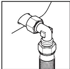
natural_image
Technical line drawing of a mechanical joint or connector (no text or symbols)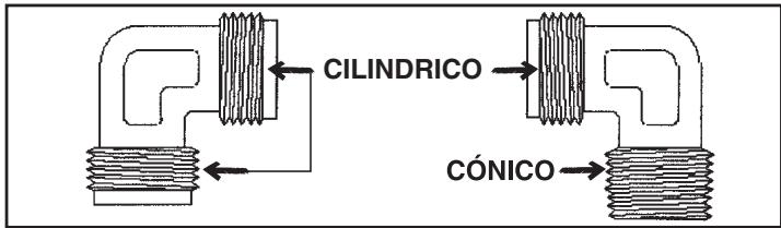
natural_image
Mechanical assembly diagram showing gears and shafts in a circular frame (no text or labels)natural_image
Pure technical diagram of concentric circular components without any text, numbers, or symbolsnatural_image
Mechanical assembly diagram showing gears and shafts in a circular frame (no text or labels)natural_image
Symbol of a trash bin crossed with a diagonal line, no text or numbers presentnatural_image
Symbol of a trash bin crossed with no text or numbers, representing waste sorting or restriction (no text present)This appliance is marked according to the European directive 2002/96/EC on Waste Electrical and Electronic Equipment (WEEE). By ensuring this product is disposed of correctly, you will help prevent potential negative consequences for the environment and human health, which could otherwise be caused by inappropriate waste handling of this product. The symbol on the product indicates that this product may not be treated as household waste.
Instead it shall be handed over to the applicable collection point for the recycling of electrical and electronic equipment Disposal must be carried out in accordance with local environmental regulations for waste disposal.
For more detailed information about treatment, recovery and recycling of this product, please contact your local city office, your household waste disposal service or the shop where you purchased the product.
IT
natural_image
Symbol of a trash bin crossed out by two diagonal lines, no text or numbers presentnatural_image
Symbol of a trash bin crossed with no text or numbers, representing waste sorting or disposal (no text present)GB The manufacturer will not be responsible for any inaccuracy resulting from printing or transcript errors contained in this brochure. We reserve the right to carry out modifications to products as required, including the interests of consumption, without prejudice to the characteristics relating to safety or function.
- INSTRUCTIONS GENERALES
- LE RACCORDEMENT ELECTRIQUE
- LES BRÛLEURS GAZ
- TO GET THE BEST FROM YOUR APPLIANCE, PLEASE READ THE FOLLOWING CAREFULLY.
- INSTALLATION
- BUILDING-IN
- GAS CONNECTION
- ELECTRICAL CONNECTION
- • CHANGING THE JETS
- • REGULATE THE AIR RING
- If necessary :
- • REGULATE THE FLAME
- a) Natural gas :
- b) Butane-propane gas :
- 1
- 2
- GAS BURNERS
- IGNITION
- RECOMMENDATIONS : when the burners are not in service, the general gas supply tap should always be turned off.
- PANS
- SOME TIPS ....
- THE ELECTRICAL HOT-PLATE
- THE ELECTRIC HOTPLATE:
- BEFORE USING THE ELECTRICAL HOT PLATE :
- HOW TO USE :
- DIFFERENT TEMPERATURE SETTINGS :
- Caution :
- CLEANING
- MAINTENANCE OF THE VITROCERAMIC or GLASS HOB
- THE GAS BURNERS
- THE PAN SUPPORT
- THE HOT PLATE
- COVER
- AFTERCARE
- Chromed grids and burners
- AVVERTENZE GENERALI
- ALLACCIAMENTO ELETTRICO
- BRUCIATORI A GAS
- IT
Brand : CANDY
Model : PLAS 640
Category : Hob