SVR-960C - Surveillance Camera Hanwha - Free user manual and instructions
Find the device manual for free SVR-960C Hanwha in PDF.

User questions about SVR-960C Hanwha
0 question about this device. Answer the ones you know or ask your own.
Ask a new question about this device
Download the instructions for your Surveillance Camera in PDF format for free! Find your manual SVR-960C - Hanwha and take your electronic device back in hand. On this page are published all the documents necessary for the use of your device. SVR-960C by Hanwha.
USER MANUAL SVR-960C Hanwha
Thank you for choosing this Samsung Digital Video Recorder product.
Before attempting to connect or operate this product,
please read the instructions contained in this manual carefully.
Please save this instruction manual for future reference.
Introduction
Thank you for choosing Samsung DVR products.
This is the user manual for SVR-3200, SVR-1680C, SVR-1660C, SVR-1645, SVR-960C, SVR-945, SVR-480. Before installing or operating this product, please familiarize yourself with this user manual and other manuals referenced by this manual.
This user manual and the software and hardware described here are protected by the copyright law. Therefore, with the exception of copying for general use within the copyright law, copying and reprinting the user manual, either partially or in its entirety, or translating it into another language without the consent of Samsung Techwin, Inc. is prohibited.
This specification may be changed without prior notice for improvement of product performance.
Product warranty and limits of responsibility
The manufacturer does not assume any other responsibility concerning the sale of this product and does not delegate any right to a third party to take any responsibility on its behalf. Product warranty does not cover cases of accidents, negligence, alteration, misuse or abuse. In addition, no warranty is offered for any attachments or parts not supplied by the manufacturer.
The warranty period for this product will be for 3 years from the date of purchase. The following cases are not covered by the warranty and payment is required for repairs.
- Malfunction due to negligence in handling by the user
◆ Deliberate disassembly and replacement by the user
◆ Connection of an improper power supply - Malfunction caused by natural disasters (fire, flood, etc.)
❖ Replacement of expendable parts (HDD, FAN, etc.)
※ Warranty period of HDD and Fan is one year after purchase.
Warranty only refers to the warranty covering products that have been paid for.
After expiration of the warranty period (3 years), examination and repair will be provided for a fee. Even during the warranty period, repair and examination of items outside the preceding warranty scope will require a payment.
This product is not for exclusive use of crime prevention but for assistance unit such as a fire or theft. Therefore, we never take any responsibility for the damage from any incident.
Various experience and technical is needed for installation of this product and an amateur installation might cause fire, electric shock, and defect. All installation operations should be performed by the agency you purchased this product from.
This manual is authored SVR-3200, SVR-1680C, SVR-1660C, SVR-1645, SVR-960C, SVR-945, SVR-480 according to firmware version 1.8.0,
Content of this manual can differ by Firmware or Software upgrade, and standard and appearance of product is changeable partly without prior notice to users.
Contents
Chapter 1. Safety Cautions....7
1.1 Explaining the Symbols....7
Chapter 2. Summary......10
2.1 Features.... 10
Chapter 3. Product Description....14
3.1 Front Part 14
3.1.1 SVR-3200....14
3.1.2 SVR-1680C, SVR-1660C, SVR-1645.... 16
3.1.3 SVR-960C 18
3.1.4 SVR-945....20
3.1.5 SVR-480....22
3.2 Rear Part.... 24
3.2.1 SVR-3200....24
3.2.2 SVR-1680C, SVR-1660C, SVR-1645 25
3.2.3 SVR-960C 26
3.2.4 SVR-945 27
3.2.5 SVR-480....28
3.3 OSD MENU structure....29
3.4 Function Menu 30
3.5 Factory setting 30
Chapter 4. Monitoring....37
4.1 Default Display....37
4.2 Single Display Full Screen....37
4.3 Multi Display....37
4.4 Auto Sequencing....37
4.4.1 Default System Mode....38
4.4 Event Screen 39
4.5 Zoom In 40
4.6 Live Video Pause 40
4.7 PTZ Control....41
4.7.1 Pan/Tilt 42
4.7.2 Zoom/Focus 42
4.7.3 Load Preset....42
4.7.4 Save Preset....42
4.7.5 Auxiliary On....42
4.7.6 Auxiliary Off....43
4.7.7 Menu 43
5.1 Playback Mode 44
5.1.1 Playback on Default Display (16/9/4 channel split-screen) 44
5.1.2 Playback....44
5.2 Search Mode....45
5.2.1 Time Search....45
5.2.2 Calendar Search 46
5.2.3 Event Search....46
5.2.4 Thumbnail Search....47
5.3 Copy 48
5.3.1 CD/DVD 48
5.3.2 RE4 50
5.3.3 AVI....51
Chapter 6. Setup .... 53
6.1 Record Setup....53
6.2 Time Setup....53
6.2.1 How to Set Time....54
6.3 Camera Setup....56
6.3.1 How to Set a Camera....57
6.4 Monitor Setup....58
6.5 Record Setup....60
6.5.1 Program Setup....60
6.5.2 Manual/Schedule Recording Setup 64
6.5.3 Evnet Record Setup....67
6.6 Audio Setup 69
6.6.1 Audio 70
6.6.2 Audio Mixing....71
6.7 General Event Setup....71
6.7.1 Text Setup 73
6.7.2 Preset....74
6.7.3 Digital I/O 75
6.7.4 Event Action 76
6.8 Network....79
6.8.1 xDSL 81
6.8.2 DDNS 82
6.8.3 NTP 87
6.8.4 Remote....88
6.9 System Setup....96
6.9.1 System Setup....96
6.9.2 Disk 99
6.9.3 Security 101
6.10 Exit 103
Chapter 7. Web Viewer .... 104
7.1 System Requirements .... 104
7.2 LOGIN....105
7.3 Connection User setup 105
7.4 Supported Browser 106
7.5 Monitor....107
7.5.1 Screen Partition & Image Movement.... 107
7.5.2 Moving Playback....108
7.5.3 Channel On/Off 108
7.5.4 Sensor indication....108
7.5.5 Relay operation....109
7.5.6 Microphone use....109
7.5.7 Event Data 109
7.5.8 Video Recording & Video Storage 110
7.5.9 PTZ Use 110
7.5.10 Audio Use....111
7.5.11 Image Channel Close 112
7.6 Playback 112
7.6.1 Screen Division & Channel Change.... 112
7.6.2 Image Recording.... 112
7.6.3 Print.... 113
7.6.4 Move to Web Monitor.... 113
7.6.5 Channel On/Off 113
7.6.6 Recording Duration & Recording Size Check.... 113
7.6.7 Calendar Search 114
7.6.8 Playback Toolbar.... 114
Trouble Shooting 114
Compatible HDD List 117
Compatible Media List.... 117
Specification 117
Dimensions 122
Chapter 1. Safety Cautions
1.1 Explaining the Symbols

Warning
Refers to information users need to know in order to prevent serious injury or death.
Before installation
Verify the supplied voltage (AC100V\~AC240V) before connecting to the power supply.
Make sure the power supply is off before installation.
Do not install in a very humid environment. Doing so may cause an electric shock or fire.
Make sure ground line is connected to reduce electric shock risk.
During operation
Do not open the product cover except by qualified personnel or system installer. Opening the product cover may cause an electric shock.
Do not plug multiple appliances into a single power outlet. Doing so may cause fire.
Do not place dishes holding water or heavy objects on the product. Doing so may cause a malfunction.
Do not use in areas where inflammable substances such as propane gas or gasoline or high amount of dust is present. Doing so may cause an explosion or fire.
Do not touch the power line with a wet hand. Doing so may cause an electric shock.
Do not insert a hand into the opening of the DVD. Doing so may cause an injury.
Make sure conductive materials do not enter the cooling ventilator opening.
Do not apply excessive force when pulling on the power cord. Damaging the cord may cause an electric shock or fire.
Improper replacement of the built-in battery by other types of batteries may cause explosion. The batter must be replaced by the same battery type. Also, expired batteries may cause pollution and must be disposed of with care.
Do not place the battery in fire or in extreme heat. Also, do not dissect or disassemble the battery.
Recharge the batteries for the remote controller.
◆ Dismantling and cleaning
Do not dismantle, repair or modify the product deliberately. Doing so may cause a damage, an electric shock or an injury.
Do not use water, paint thinner or organic solvent for cleaning the product exterior. Doing so may cause a malfunction or an electric shock. Use a dry cloth to clean the exterior.

Caution
Provides information users need to know in order to prevent minor injury or product damage.
During installation
For adequate ventilation, install the product with at least 15cm of space between the cooler and the wall surface.
To prevent falling, install the product on a flat area. Dropping the product may cause an injury or a malfunction.
Avoid areas exposed to direct exposure to sun light or excessive heat since they may cause deformation or a malfunction.
If a camera is installed while the DVR is being recorded, image in another channel may be disrupted. Starting the storage after the camera has been installed is recommended.
During use
Make sure the product is not exposed to concussions or shaking during usage or movement.
Do not move, throw or expose to excessive physical concussion during usage.
Installing additional unapproved hard disk drives may result in abnormal operation. Inquire at the agency of purchase before installing additional hard disk drives.
Product warranty will not cover malfunctions due to additional installation of unapproved hard disk drives.
This product is a supplementary rather than primary means for preventing fire and theft. Our company is not responsible for accidents or damage that may occur.
Samsung Techwin recommends the installation of a UPS (Uninterrupted Power
Supply) with all its recording products.

text_image
eco RoHS compliantSamsung Techwin cares for the environment at all product manufacturing stages, and is taking a number of steps to provide customers with more environmentally friendly products. The Eco mark represents Samsung Techwin's will to create environmentally friendly products, and indicates that the product satisfies the EU RoHS Directive.
FCC Compliance Statement
NOTE : This equipment has been tested and found to comply with the limits for a Class A digital device, pursuant to part 15 of the FCC Rules. These limits are designed to provide reasonable
protection against harmful interference when the equipment is operated in a commercial environment. This equipment generates, uses, and can radiate radio frequency energy and, if not installed and used in accordance with the instruction manual, may cause harmful interference to radio communications. Operation of this equipment in a residential area is likely to cause harmful interference in which cause the user will be required to correct the interference at his own expense.
Correct Disposal of This Product
(Waste Electrical & Electronic Equipment)

(Applicable in the European Union and other European countries with separate collection systems.) This marking shown on the product or its literature, indicates that it should not be disposed with other household wastes at the end of its working life. To prevent possible harm to the environment or human health from uncontrolled waste disposal, please separate this from other types of wastes and recycle it responsibly to promote the sustainable reuse of material resources. Household users should contact either the retailer where they purchased this product, or their local government office, for details of where and how they can take this item for environmentally safe recycling. Business users should contact their supplier and check the terms and conditions of the purchase contract. This product should not be mixed with other commercial wastes for disposal.
Correct Disposal of Batteries in this Product
(Applicable in the European Union and other European countries with separate battery return systems.)

This marking on the battery, manual or packaging indicates that the batteries in this product should not be disposed of with other household waste at the end of their working life. Where marked, the chemical symbols Hg, Cd or Pb indicate that the battery contains mercury, cadmium or lead above the reference levels in EC Directive 2006/66. If batteries are not properly disposed of, these substances can cause harm to human health or the environment. To protect natural resources and to promote material reuse, please separate batteries from other types of waste and recycle them through your local, free battery return system. The rechargeable battery incorporated in this product is not user replaceable.
For information on its replacement, please contact your service provider.
Chapter 2. Summary
This unit is a digital video recording and playback device to record image and video input from 32/16/9/4 channels to its built-in hard disk. The buttons on the front of the unit as well as the mouse and GUI allow easy setup and operation.
The Samsung SVR series of digital video recorders (DVRs) provide additional safety and security to banks, apartment buildings and complexes, government offices as well as other public, private and commercial facilities. Recorded high-quality video and images are stored on hard disk for later retrieval or playback. Real time functionality delivers users with the ability to simultaneously record multiple channels, playback video, and copy video. A few of the more advanced user-conveniences include motion detection, Pan/Tilt/Zoom controls (PTZ), password protection, real time audio recording, event lists, and log files.
2.1 Features
Monitoring Screen
The monitoring screen supports vivid, high-definition live visual feed from each channel and provides multiple screens.
Real time MPEG-4 visual output (480 frames)
◆ Multiple split-screen monitoring modes
SVR-3200/1680C/1660C/1645: Single, 4, 9, 10, 16
SVR-960C/945: Single, 4, 9
SVR-480 : Single, 4
❖ Automatic Screen Switching (AUTO)
◆ Supports various monitor output modes
SVR-3200: 4 Composite, 2 VGA
SVR-1680C: 4 Composite, 1 VGA
SVR-1660C/1645/960C/945/480: 2 Composite, 1 VGA
Pan/Tilt, Digital Zoom, PIP (Picture-In-Picture), The PIP function will be available with a firmware upgrade in the future.
Audio Recording
SVR series DVRs provide real time audio recording.
- Simultaneous recording of 16/9/4 channels of audio in real time
SVR-3200/1680C/1600/1645 : Input - 16 channels (4 RCA in rear, 12 D-SUB),
Output - 1 in rear, SVR-960C/945 : 9 channels (4 RCA in rear, 5 D-SUB),
Output - 1 in rear, SVR-480 : 4 channels (4RCA), Output - 1 in rear
◆ Supports simultaneous recording and playback
Video Recording
The product is capable of storing visual image data as high resolution MPEG-4 video at up to 480 frames per second, as well as pre-emptively initiating recording sequences up to five seconds prior to an event. The COVERT feature (concealment of private visual data) helps to protect privacy.
◆ High quality real time MPEG-4 recording
- Three screen-resolution levels for improved control over data sizes
- Multi-recording for manual and scheduled events
Simultaneous recording/playback/backup/networking
✿ Easily accessible options for channel-specific resolution and motion detection ranges
Per-second frame rates (up to 30 frames per channel) are user customizable SVR-3200 Half D1 : NTSC (704x240) 960fps, PAL (704x288) 800fps SVR-1680C D1 : NTSC (704x480) 480fps, PAL (704x576) 400fps SVR-1660C/1645 CIF : NTSC (352x240) 480fps, PAL (352x288) 400fps SVR-960C/945 CIF : NTSC (352x240) 270fps, PAL (352x288) 225fps SVR-480 D1 : NTSC (704x480) 120fps, PAL (704x576) 100fps
◆ Manual and scheduled recording
◆ Video signal loss detection
Event logs (sensors, D-I/O, video loss, motion detection, text)
✿ Each channel supports pre-emptive recording sequences up to 5 seconds prior to an actual event
Search/Playback
Various search and playback options are offered for the user's convenience.
❖ Playback by time, date and channel
- Mouse interface increases data searchability
◆ Forward/backward search while playback is paused
❖ Playback by event log entry (sensor, video loss, motion detection and text)
Remote controller and Jog/Shuttle further improve searching (The SVR-960C/945/480 models do not support Jog/Shuttle.)
◆ Full-frame playback (Available in SVR-3200/1680C/1660C only)
Data Storage
The hard disk included with the product is for data storage. If desired, recorded data can be backed up or stored to DVD-R, CD-R or a USB storage device.
- The built-in hard disk is provided as primary storage
Multiple portable data storage media are supported: DVD-R, CD-R and USB
※ Refer to the appendix on the back of the manual regarding compatible media types.
✿ Hard disk expansion device (external recording device): SVS-5E (optional) External hard disk expansion is supported with the SVS-5E (Available for purchase separately)
Networking
The product supports LAN, xDSL and other networking capabilities. Combined with the PC interface client, the core features of the device can be easily remotely controlled.
❖ E-mails can be sent via TCP/IP or DHCP upon an event trigger
◆ Remote live visual feed (single or 4 section split-screen)
PC playback, storage, search and DVR control functions via Network Viewer
◆ Remote recording, search and playback scheduling
◆ Supports 10/100Mbps Ethernet/xDSL
◆ Multiple DVR connections
Miscellaneous
❖ User-friendly GUI and mouse interface
❖ Simplified firmware upgrades through USB
❖ Visual data recording and backup to USB
◆ Supports PTZ control (SPEED DOME), Coax, PRESET
✿ Multilingual support: Korean, English, Italian, Spanish, Japanese
◆ Single remote controller to control 16 DVRs
Chapter 3. Product Description
3.1 Front Part
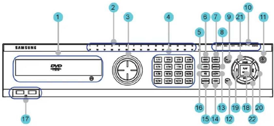
3.1.1 SVR-3200
text_image
SAMSUNG DVD 17 2 3 4 5 6 7 8 9 10 11 12 13 14 15 16 17 18 19 20 21 22 23 24 25 26 27 28 29 30 31 32 33 34 35 36 37 38 39 40 41 42 43 44 45 46 47 48 49 50 51 52 53 54 55 56 57 58 59 60 61 62 63 64 65 66 67 68 69 70 71 72 73 74 75 76 77 78 79 80 81 82 83 84 85 86 87 88 89 90 91 92 93 94 95 96 97 98 99 100| No. | Classification Function | |
| 1 | DVD-Multi for copying | For copying recorded video and images to DVD/CD optical media. |
| 2 | Channel LED Shows the data input and event operation status | |
| 3 | JOG/SHUTTLE | Jog can adjust setting values, control the STEP function, navigate through the menu, and adjust the playback speed and direction. Shuttle controls PTZ. |
| 4 | Channel button Selects channel in live feed or playback | |
| 5 | AUTO Starts or stops user defined sequences. | |
| 6 | MULTI Changes split-screen sections for live video feeds or playback. | |
| 7 | MENU Navigates into the Menu. | |
| 8 | SEARCH Starts Search mode. | |
| 9 | REC button Starts or stops manual recording | |
| 10 | REC lamp | Lit when recording. |
| HDD lamp | Lit when HDD is working. | |
| NETWORK lamp | Lit when network is connected. | |
| EVENT lamp | Lit when an event is detected. | |
| COPY lamp Indicates copying operation. | ||
| PLAY lamp Lit when copying. | ||
| 11 Power button Turns on or off the device. | ||
| 12 ESC button The Escape button navigates up the menu tree and closes dialog windows. | ||
| 13 COPY Starts Copy mode. | ||
| 14 FUNC Starts Function mode. | ||
| 15 MONITOR Cycles through from Monitor 1 to 4. | ||
| 16 PTZ Starts or ends PTZ function. | ||
| 17 USB1, USB2 | USB ports for external devices (mouse, USB memory stick). | |
| 18 PLAY/ENTER Start playback or select an item on the menu. | ||
| 19 ◀/REW | Navigates or selects in the menu, or for playback, changes the reverse playback speed. | |
| 20 ▶/FWD | Navigates or selects in the menu, or for playback, changes the forward playback speed. | |
| 31 ▲/PAUSE | Navigates or selects in the menu, or for playback, pauses live or recorded video. | |
| 22 ▼/STOP | Navigates or selects in the menu, or for playback, stops playback. | |
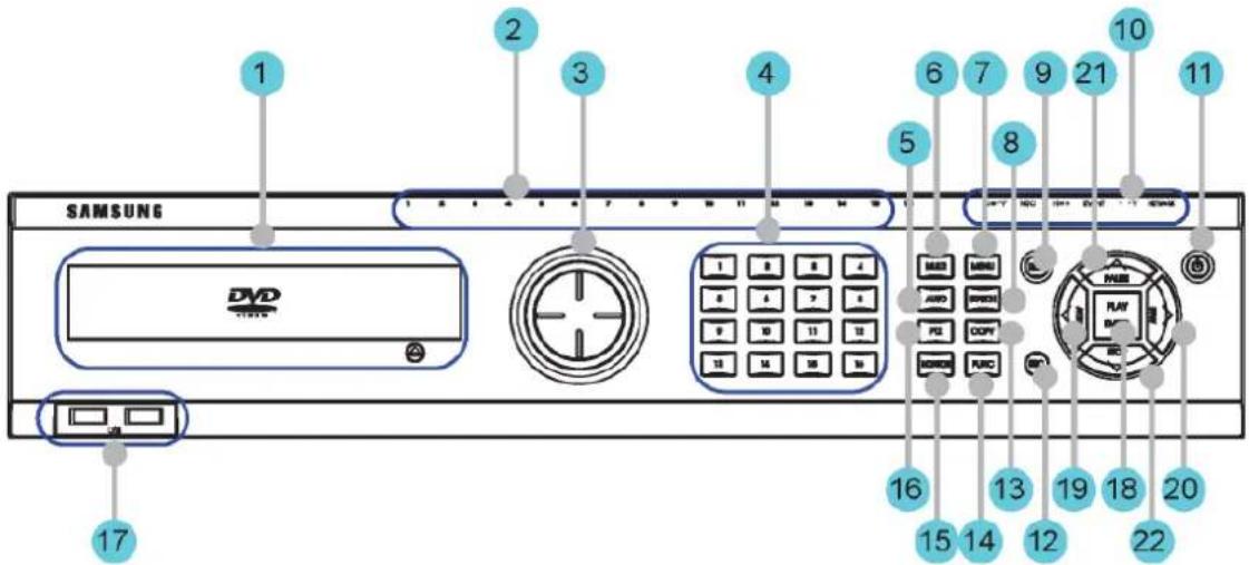
3.1.2 SVR-1680C, SVR-1660C, SVR-1645
text_image
SAMSUNG DVD 1 2 3 4 5 6 7 8 9 10 11 12 13 14 15 16 17 18 19 20 21 22| No. | Classification Function | |
| 1 | DVD-Multi for copying | For copying recorded video and images to DVD/CD optical media. |
| 2 | Channel LED Shows the data input and event operation status | |
| 3 | JOG/SHUTTLE | Jog can adjust setting values, control the STEP function, navigate through the menu, and adjust the playback speed and direction. Shuttle controls PTZ. |
| 4 | Channel button Selects channel in live feed or playback | |
| 5 | AUTO Starts or stops user defined sequences. | |
| 6 | MULTI Changes split-screen sections for live video feeds or playback. | |
| 7 | MENU Navigates into the Menu. | |
| 8 | SEARCH Starts Search mode. | |
| 9 | REC button Starts or stops manual recording | |
| 10 | REC lamp | Lit when recording. |
| HDD lamp | Lit when HDD is working. | |
| NETWORK lamp | Lit when network is connected. | |
| EVENT lamp | Lit when an event is detected. | |
| COPY lamp | Indicates copying operation. | |
| PLAY lamp | Lit when copying. | |
| 11 | Power button Turns on or off the device. | |
| 12 | ESC button The Escape button navigates up the menu tree and | |
| closes dialog windows. | ||
| 13 COPY Starts Copy mode. | ||
| 14 | FUNC Starts Function mode. | |
| 15 | MONITOR Cycles through from Monitor 1 to 4 : SVR-1680C, Switches from main and sub monitor : SVR-1660C, SVR-1645 | |
| 16 PTZ Starts or ends PTZ function. | ||
| 17 | USB1, USB2 | USB ports for external devices (mouse, USB memory stick). |
| 18 PLAY/ENTER Start playback or select an item on the menu. | ||
| 19 | ◀/REW | Navigates or selects in the menu, or for playback, changes the reverse playback speed. |
| 20 | ▶/FWD | Navigates or selects in the menu, or for playback, changes the forward playback speed. |
| 31 | ▲/PAUSE | Navigates or selects in the menu, or for playback, pauses live or recorded video. |
| 22 | ▼/STOP | Navigates or selects in the menu, or for playback, stops playback. |
text_image
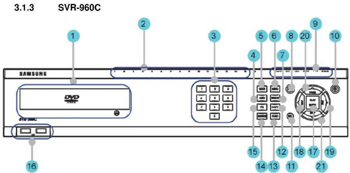
3.1.3 SVR-960C SAMSUNG DVD STE-3MC 16 2 3 4 5 6 7 8 9 10 11 12 13 14 15 16 17 18 19 20 21 22 23 24 25 26 27 28 29 30 31 32 33 34 35 36 37 38 39 40 41 42 43 44 45 46 47 48 49 50 51 52 53 54 55 56 57 58 59 60 61 62 63 64 65 66 67 68 69 70 71 72 73 74 75 76 77 78 79 80 81 82 83 84 85 86 87 88 89 90| No. | Classification Function | |
| 1 | DVD-Multi for copying | For copying recorded video and images to DVD/CD optical media. |
| 2 | Channel LED Shows the data input and event operation status | |
| 3 | Channel button Selects channel in live feed or playback | |
| 4 | AUTO Starts or stops user defined sequences. | |
| 5 | MULTI Changes split-screen sections for live video feeds or playback. | |
| 6 | MENU Navigates into the Menu. | |
| 7 | SEARCH Starts Search mode. | |
| 8 | REC button Starts or stops manual recording | |
| 9 | REC lamp Lit when recording. | |
| HDD lamp | Lit when HDD is working. | |
| NETWORK lamp | Lit when network is connected. | |
| EVENT lamp | Lit when an event is detected. | |
| COPY lamp | Indicates copying operation. | |
| PLAY lamp | Lit when copying. | |
| 10 | Power button Turns on or off the device. | |
| 11 | ESC button The Escape button navigates up the menu tree and closes dialog windows. | |
| 12 | COPY Starts Copy mode. | |
| 13 | FUNC Starts Function mode. | |
| 14 | MONITOR Switches from main and sub monitor | |
| 15 | PTZ Starts or ends PTZ function. | |
| 16 | USB1, USB2 | USB ports for external devices (mouse, USB memory stick). |
| 17 | PLAY/ENTER Start play back or select an item on the menu. | |
| 18 | ◀/REW | Navigates or selects in the menu, or for playback, changes the reverse playback speed. |
| 19 | ▶/FWD | Navigates or selects in the menu, or for playback, changes the forward playback speed. |
| 20 | ▲/PAUSE | Navigates or selects in the menu, or for playback, pauses live or recorded video. |
| 21 | ▼/STOP | Navigates or selects in the menu, or for playback, stops playback. |
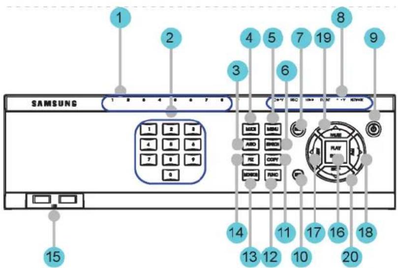
3.1.4 SVR-945
text_image
1 2 3 4 5 6 7 8 9 SAMSUNG 1 2 3 4 5 6 7 8 1 2 3 4 5 6 MOCI MENU ABO BENO RE COPY MOISO RNO 14 13 12 10 17 16 18 PLAY SE 20 15| No. | Classification Function | |
| 1 | Channel LED Shows the data input and event operation status | |
| 2 | Channel button Selects channel in live feed or playback | |
| 3 | AUTO Starts or stops user defined sequences. | |
| 4 | MULTI Changes split-screen sections for live video feeds or playback. | |
| 5 | MENU Navigates into the Menu. | |
| 6 | SEARCH Starts Search mode. | |
| 7 | REC button Starts or stops manual recording | |
| 8 | REC lamp Lit when recording. | |
| HDD lamp | Lit when HDD is working. | |
| NETWORK lamp | Lit when network is connected. | |
| EVENT lamp | Lit when an event is detected. | |
| COPY lamp | Indicates copying operation. | |
| PLAY lamp | Lit when copying. | |
| 9 | Power button Turns on or off the device. | |
| 10 | ESC button The Escape button navigates up the menu tree and closes dialog windows. | |
| 11 | COPY Starts Copy mode. | |
| 12 | FUNC Starts Function mode. | |
| 13 | MONITOR Switches from main and sub monitor | |
| 14 PTZ Starts or ends PTZ function. | ||
| 15 | USB1, USB2 | USB ports for external devices (mouse, USB memory stick). |
| 16 PLAY/ENTER Start play back or select an item on the menu. | ||
| 17 | ◀/REW | Navigates or selects in the menu, or for playback, changes the reverse playback speed. |
| 18 | ▶/FWD | Navigates or selects in the menu, or for playback, changes the forward playback speed. |
| 19 | ▲/PAUSE | Navigates or selects in the menu, or for playback, pauses live or recorded video. |
| 20 | ▼/STOP | Navigates or selects in the menu, or for playback, stops playback. |
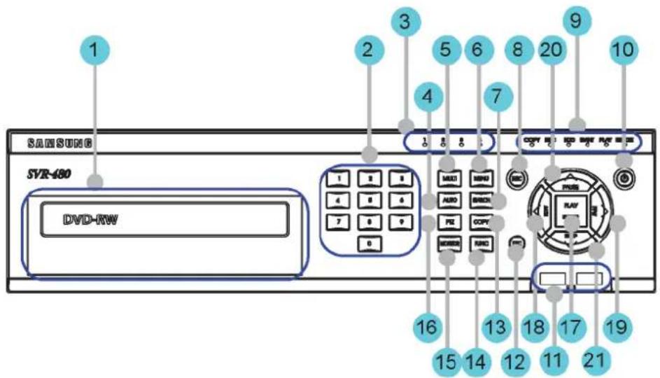
3.1.5 SVR-480
text_image
1 SAMSUNG SVR-480 DVD-RW 2 3 4 5 6 7 8 9 10 COPY 10 ADD 10 ADD 10 ADD 10 ADD 10 ADD 10 ADD 10 ADD 10 ADD 10 ADD 10 ADD 10 ADD 10 ADD 10 ADD 10 ADD 10 ADD 10 ADD 10 ADD 10 ADD 10 ADD 10 ADD 10 16 15 14 13 12 18 17 11 21 21| No | Classification Function | |
| 1 | DVD-Multi for copying | For copying recorded video and images to DVD/CD optical media. |
| 2 | Channel button Selects channel in live feed or playback | |
| 3 | Channel LED Shows the data input and event operation status | |
| 4 | AUTO Starts or stops user defined sequences. | |
| 5 | MULTI Changes | split-screen sections for live video feeds or playback. |
| 6 | MENU Navigates into the Menu. | |
| 7 | SEARCH Starts Search mode. | |
| 8 | REC button Starts or stops manual recording | |
| 9 | REC lamp Lit when recording. | |
| HDD lamp | Lit when HDD is working. | |
| NETWORK lamp | Lit when network is connected. | |
| EVENT lamp | Lit when an event is detected. | |
| COPY lamp | Indicates copying operation. | |
| PLAY lamp | Lit when copying. | |
| 10 | Power button Turns on or off the device. | |
| 11 | USB1, USB2 | USB ports for external devices (mouse, USB memory stick). |
| 12 | ESC button | The Escape button navigates up the menu tree and closesdialog windows. |
| 13 COPY Starts Copy mode. | ||
| 14 FUNC Starts Function mode. | ||
| 15 MONITOR Switches from main and sub monitor | ||
| 16 PTZ Starts or ends PTZ function. | ||
| 17 PLAY/ENTER Start playback or select an item on the menu. | ||
| 18 | ◀/REW | Navigates or selects in the menu, or for playback, changes the reverse playback speed. |
| 19 | ▶/FWD | Navigates or selects in the menu, or for playback, changes the forward playback speed. |
| 20 | ▲/PAUSE | Navigates or selects in the menu, or for playback, pauses live or recorded video. |
| 21 | ▼/STOP | Navigates or selects in the menu, or for playback, stops playback. |
3.2 Rear Part
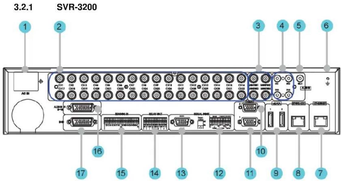
| No. | Input/Output terminal name | Function |
| 1 | POWER IN Socket for AC 100V ~ AC 240V power cord. | |
| 2 | CH1 ~ 32 Connection terminal for camera BNC input. | |
| 3 | MONITOR 1 ~ 4 Connection terminal for monitor BNC output. | |
| 4 | AUDIO IN(RCA) RCA audio jack for RCA input. | |
| 5 | AUDIO OUT Audio jack for speaker output. | |
| 6 | GROUND Ground terminal between DVR and external device. | |
| 7 | ETHERNET Ethernet port for network connections (RJ-45). | |
| 8 | STORAGE External storage connection port (Function not supported in the current version) | |
| 9 | eSATA Connection terminal for external eSATA HDD or HDD for backups. | |
| 10 | VGA OUTPUT 2 | Output port for PC monitor. |
| 11 | VGA OUTPUT 1 | Output port for PC monitor. |
| 12 | Serial Port (Terminal Block)RS-232C/485/422 | Connection terminal for expanded controller, speed dome camera, etc. |
| 13 | Serial Port (D-Sub) | RS-232C D-SUB connector. |
| 14 | RELAY OUT Connection terminal for relay output. | |
| 15 | SENSOR IN Connection terminal for sensor input. | |
| 16 | AUDIO IN(D-SUB) Connection terminal for audio output D-SUB. | |
| 17 | D-I/O Connection terminal for DIGITAL IN/OUT. | |
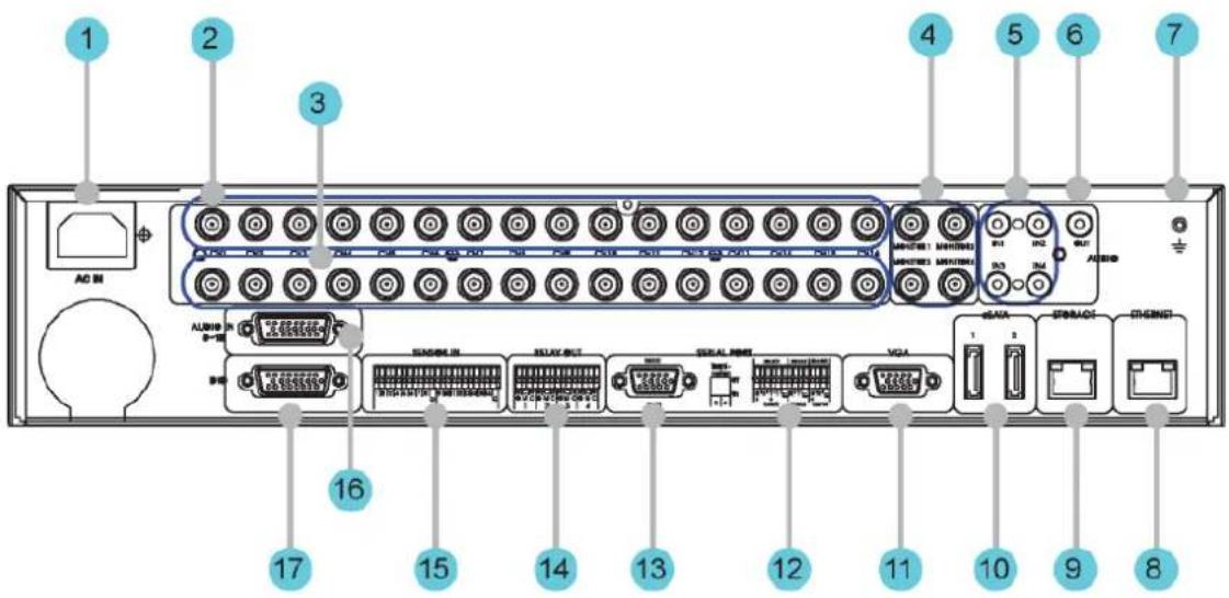
3.2.2 SVR-1680C, SVR-1660C, SVR-1645
text_image
1 2 3 4 5 6 7 AD M ALUMIN 16 17 15 14 13 12 11 10 9 8| No. | Input/Output terminal name | Function |
| 1 | POWER IN Socket for AC 100V ~ AC 240V power cord. | |
| 2 | CH1~16 Connection terminal for camera BNC input. | |
| 3 | LOOP OUT Connection terminal for camera BNC output (loop). | |
| 4 | MONITOR 1 ~ 2 Connection terminal for monitor BNC output. | |
| 5 | AUDIO IN(RCA) RCA audio jack for RCA input. | |
| 6 | AUDIO OUT Audio jack for speaker output. | |
| 7 | GROUND Ground terminal between DVR and external device. | |
| 8 | ETHERNET Ethernet port for network connections (RJ-45). | |
| 9 | STORAGE External storage connection port (Function not supported in the current version) | |
| 10 | eSATA Connection terminal for external eSATA HDD or HDD for backups. | |
| 11 | VGA OUTPUT Output port for PC monitor. | |
| 12 | Serial Port (Terminal Block) RS-232C/485/422 Connection terminal for expanded controller, speed dome camera, etc. | |
| 13 | Serial Port (D-Sub) RS-232C D-SUB connector. | |
| 14 | RELAY OUT Connection terminal for relay output. | |
| 15 | SENSOR IN Connection terminal for sensor input. | |
| 16 | AUDIO IN(D-SUB) Connection terminal for audio output D-SUB. | |
| 17 | D-I/O Connection terminal for DIGITAL IN/OUT. | |
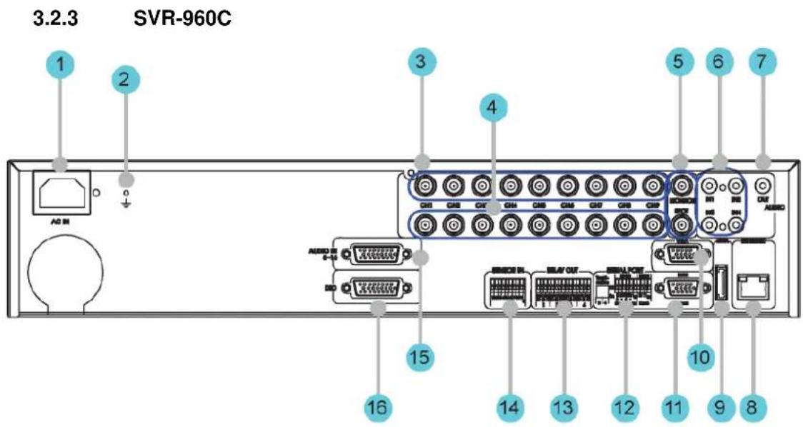
text_image
3.2.3 SVR-960C 1 2 3 4 5 6 7 AD M AUDIO AUDIO AUDIO AUDIO AUDIO AUDIO AUDIO AUDIO AUDIO AUDIO AUDIO AUDIO AUDIO AUDIO AUDIO AUDIO AUDIO AUDIO AUDIO AUDIO AUDIO AUDIO AUDIO AUDIO AUDIO AUDIO AUDIO AUDIO AUDIO AUDIO AUDIO AUDIO AUDIO AUDIO AUDIO AUDIO AUDIO AUDIO AUDIO AUDIO AUDIO AUDIO AUDIO AUDIO AUDIO AUDIO AUDIO AUDIO AUDIO AUDIO AUD M AUD M AUD M AUD M AUD M AUD M AUD M AUD M AUD M AUD M AUD M AUD M AUD M AUD M AUD M AUD M AUD M AUD M AUD M AUD M AUD M AUD M AUD M AUD M AUD M AUD M AUD M| No. | Input/Output terminal name | Function |
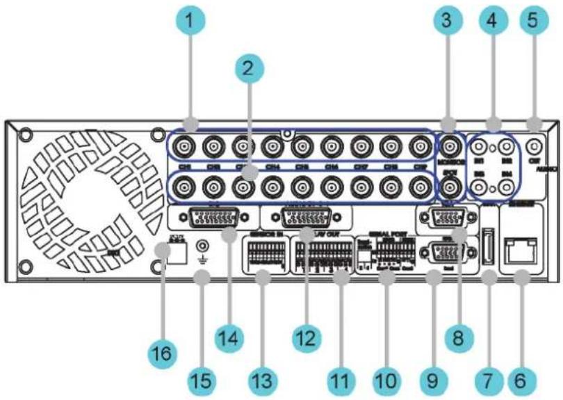
| 1 | POWER IN Socket for AC 100V ~ AC 240V power cord. | |
| 2 | GROUND Ground terminal between DVR and external device. | |
| 3 | CH1~9 Connection terminal for camera BNC input. | |
| 4 | LOOP OUT Connection terminal for camera BNC output (loop). | |
| 5 | MONITOR 1 ~ 2 Connection terminal for monitor BNC output. | |
| 6 | AUDIO IN(RCA) RCA audio jack for RCA input. | |
| 7 | AUDIO OUT Audio jack for speaker output. | |
| 8 | ETHERNET Ethernet port for network connections (RJ-45). | |
| 9 | eSATA Connection terminal for external eSATA HDD or HDD for backups. | |
| 10 | VGA OUTPUT Output port for PC monitor. | |
| 11 | Serial Port (D-Sub) | RS-232C D-SUB connector. |
| 12 | Serial Port (Terminal Block) | Connection terminal for expanded controller, speed dome camera, etc. |
| RS-232C/485/422 | ||
| 13 | RELAY OUT Connection terminal for relay output. | |
14 SENSOR IN Connection terminal for sensor input.
15 AUDIO IN(D-SUB) Connection terminal for audio output D-SUB.
16 D-I/O Connection terminal for DIGITAL IN/OUT.
3.2.4 SVR-945
text_image
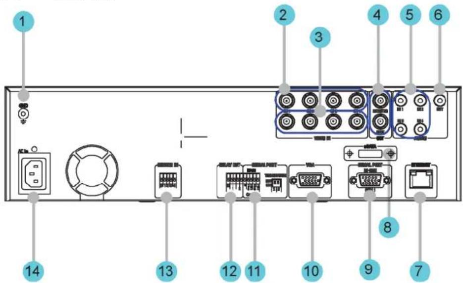
1 2 3 4 5 16 15 14 13 12 11 10 9 8 7 6| No. | Input/Output terminal name | Function |
| 1 | CH1~9 Connection terminal | for camera BNC input. |
| 2 | LOOP OUT Connection terminal | for camera BNC output (loop). |
| 3 | MONITOR 1 ~ 2 Connection | terminal for monitor BNC output. |
| 4 | AUDIO IN(RCA) RCA audio | jack for RCA input. |
| 5 | AUDIO OUT Audio jack for speaker output. | |
| 6 | ETHERNET Ethernet port for network connections (RJ-45). | |
| 7 | eSATA Connection terminal | for external eSATA HDD or HDD for backups. |
| 8 | VGA OUTPUT Output port for PC monitor. | |
| 9 | Serial Port (D-Sub) | RS-232C D-SUB connector. |
| 10 | Serial Port (Terminal Block) RS-232C/485/422 | Connection terminal for expanded controller, speed dome camera, etc. |
| 11 | RELAY OUT Connection terminal for relay output. | |
| 12 | AUDIO IN(D-SUB) | Connection terminal for audio output D-SUB. |
| 13 | SENSOR IN | Connection terminal for sensor input. |
| 14 | D-I/O Connection terminal for DIGITAL IN/OUT. |
| 15 | GROUND Ground terminal between DVR and external device. |
| 16 | POWER IN Socket for AC 100V ~ AC 240V power cord. |
3.2.5 SVR-480
text_image
1 2 3 4 5 6 14 13 12 11 10 8 9 7| No. | Input/Output terminal name | Function |
| 1 | GROUND Ground terminal between DVR and external device. | |
| 2 | CH1~4 Connection terminal for camera BNC input. | |
| 3 | LOOP OUT Connection terminal for camera BNC output (loop). | |
| 4 | MONITOR 1 ~ 2 Connection terminal for monitor BNC output. | |
| 5 | AUDIO IN(RCA) RCA audio jack for RCA input. | |
| 6 | AUDIO OUT Audio jack for speaker output. | |
| 7 | ETHERNET Ethernet port for network connections (RJ-45). | |
| 8 | eSATA Connection terminal for external eSATA HDD or HDD f o backups. | |
| 9 | Serial Port (D-Sub) | RS-232C D-SUB connector. |
| 10 | VGA OUTPUT Output port for PC monitor. | |
| 11 | Serial Port (Terminal Block) RS-485/422 | Connection terminal for expanded controller, speed dome camera, etc. |
| 12 | RELAY OUT Connection terminal for relay output. | |
| 13 | SENSOR IN Connection terminal for sensor input. | |
| 14 | POWER IN Socket for AC 100V ~ AC 240V power cord. | |

Refer to detailed description for installation & use from "Install Manual".
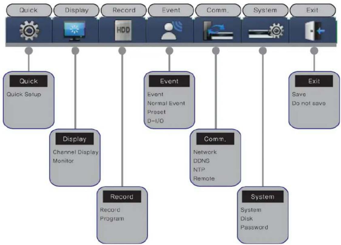
3.3 OSD MENU structure
The menu structure is as shown below. For detailed instructions for configuration, please refer to Chapter 4, 5 and 6.
flowchart
graph TD
    A["Quick Setup"] --> B["Display"]
    B --> C["Record Program"]
    C --> D["Record"]
    D --> E["Comm. Remote"]
    E --> F["System"]
    F --> G["Exit"]

    H["Quick Setup"] --> I["Display"]
    I --> J["Record Program"]
    J --> K["Comm. Remote"]
    K --> L["System"]
    L --> M["Exit"]

    N["Display"] --> O["Channel Display Monitor"]
    O --> P["Record Program"]
    P --> Q["Comm. Remote"]
    Q --> R["System"]
    R --> S["Exit"]

    T["Event"] --> U["Event Normal Event Preset D-I/O"]
    U --> V["Comm. Remote"]
    V --> W["System"]
    W --> X["Exit"]

    Y["Comm. Remote"] --> Z["Network DDNS NTP Remote"]
    Z --> AA["System Disk Password"]
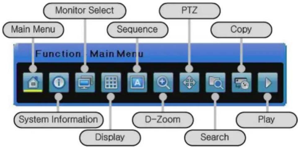
3.4 Function Menu
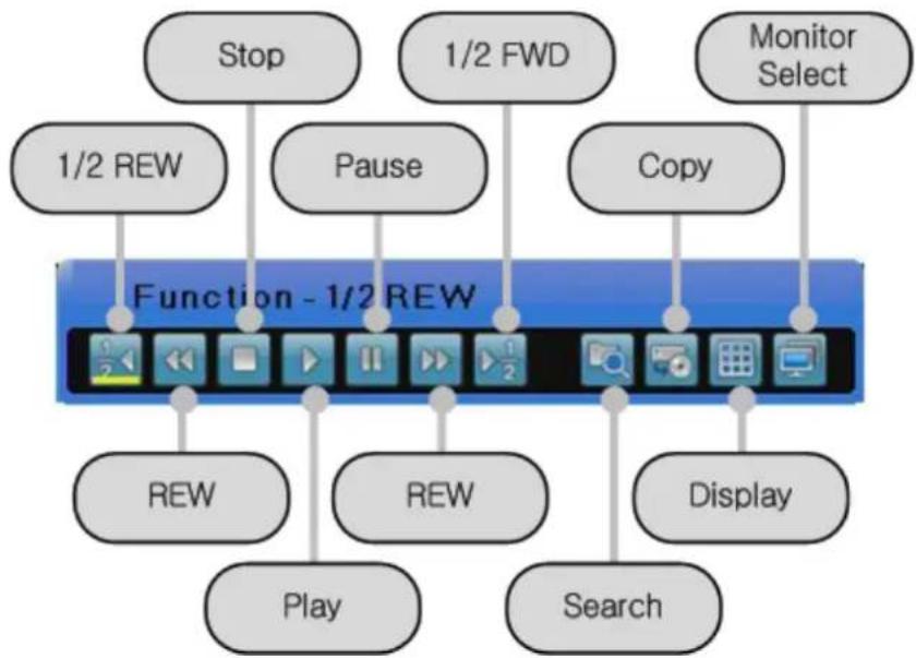
The function menu allows the users to access any and all functions and operations of the product with the mouse. To execute a particular function, left-click the icon. Also, all functions listed in the function menu can be executed in full-screen mode. The function menu structure is as shown below.
Live Function Menu
flowchart
graph TD
    A["Monitor Select"] --> B["Main Menu"]
    C["PTZ"] --> D["Sequence"]
    E["Copy"] --> F["Copy"]
    G["System Information"] --> H["Display"]
    I["D-Zoom"] --> J["Search"]
    K["Play"] --> L["Play"]
    M["System Information"] --> N["Display"]
    O["System Information"] --> P["Display"]
    Q["System Information"] --> R["Display"]
    S["System Information"] --> T["Display"]
    U["System Information"] --> V["Display"]
    W["System Information"] --> X["Display"]
    Y["System Information"] --> Z["Display"]
Playback Function Menu
flowchart
graph TD
    A["Stop"] --> B["1/2 REW"]
    C["1/2 FWD"] --> D["Pause"]
    E["Monitor Select"] --> F["Copy"]
    B --> G["Function - 1/2 REW"]
    D --> G
    F --> G
    G --> H["REW"]
    G --> I["REW"]
    G --> J["Display"]
    H --> K["Play"]
    I --> L["Search"]
3.5 Factory setting
To restore the unit back to its factory settings, go to System > System > Restore Factory Setting. A pop-up window saying, "Warning : The system will be reset. Continue with restoring factory default?" will appear. Select "Yes" and press Enter to restore the factory default settings.
Factory Default
| Quick Setup | |||
| Record Mode ii Manual & Event | |||
| Schedule | Not Set | ||
| Event Check | Always | ||
| Language | English | ||
| Time ii UTC 00:00 Dublin | |||
| Display Setup | |||
| Channel Display | Channel Number | Ch1 | |
| Title Cam | 1 | ||
| Status | Enable | ||
| Color | Color | ||
| AGC Enable | |||
| Brightness | 0 | ||
| Contrast | 0 | ||
| Monitor | Monitor Number | Main Monitor (Monitor 1) | |
| Covert Channel | Deselect All | ||
| Sequencing | Number 1 is set to Channel 1 and Number 2 is set to Channel 2 in order. | ||
| Dwell Time | 5 sec. | ||
| Multi Display 4E Channels 1, 3, 5 and 7 | |||
| VGA Mode | 800x600@56Hz | ||
| On Screen Display | Select All | ||
| Record Setup | |||
| Record | Record Mode | Schedule & Event | |
| Schedule | Not Set All | ||
| Event Duration | Before: 1 sec., After: 1 sec. | ||
| Repeat Record Mode | On | ||
| Warning Level | ii 45% | ||
| Record Data Retention | Off | ||
| PlaybackDeinterlace | On | ||
| Audio | >> | ||
| AudioChannel | Ch1 | ||
| AudioRecording | Off | ||
| Audio Gain 0 | |||
| Sync Video Channel | Ch1 | ||
| Audio Mix Mix | On | ||
| Program A~ | Z ii CIF, 0fps, Q1 | ||
| Event Setup | |||
| Event | Event Check | Always | |
| Event Screen /Dwell time | Monitor 1 Off | ||
| Event Source | Deselect All | ||
| Event Action | Relay 1 | ||
| Action Duration | 10 sec. | ||
| Normal Event Source | Deselect All | ||
| System Event Source | Deselect All | ||
| Normal Event | MD | All Channel | |
| MD | Sensitivity | 2 | |
| Area | Set All | ||
| Sensor | All Sensor | N.O | |
| Text | >> | ||
| Recording | Off | ||
| Sync Text With | Ch1 | ||
| Device | Manual | ||
| Seek Header | Off | ||
| Header 1 | header1 | ||
| Header 2 | header2 | ||
| Delimiter | 0D0A | ||
| Timeout(ms) | 1000 | ||
| Lines | 20 | ||
| Preset | Channel Number | Ch1 | |
| Preset | Not | Set | |
| D-I/O | D-I/O | Output | |
| Output Type | Sensor | ||
| Network | |||
| Network | Type | Ethernet | |
| DHCP | Off | ||
| IP addr | Default | IP | |
| Net Mask | Default | NM | |
| Gateway | Default | GW | |
| DNS1 | 0.0.0.0 | ||
| Additional DNS | 0.0.0.0 | ||
| Port | 4000 | ||
| BandWidthLimit(Mbps) | 0 | ||
| xDSL | User ID | ii | guest |
| Password | ***** | ||
| Status | xDSL not connected. | ||
| Port | 4000 | ||
| Bandwidth Limit(Mbps) | 0.0 | ||
| DDNS | Interval | Off | |
| Server | www.samsungipolis.com | ||
| ID | None | ||
| Password | None | ||
| Status | Not | Registered | |
| NTP | Sync With NTP | Off | |
| NTP Mode | Client | ||
| NTP Server Loc. | ii | Public | |
| NTP Local Server IP | 0.0.0.0 | ||
| Interval | 1 (hour) | ||
| Remote | Remote Keyboard ID | 1 | |
| Remote Controller | All | ||
| ID | |||
| RemoteConfiguration Setup | Enable | ||
| Remote Relay | Enable | ||
| Serial | Com1, | >> | |
| PTZ | Ch1, >> | ||
| System Setup | |||
| System | Language | English | |
| Key Buzzer | On | ||
| Default | >> | ||
| Load/SaveConfiguration | Load, >> | ||
| Firmware Update | >> | ||
| DVR Alias | DVR0 | ||
| System Log | >> | ||
| Time | >> | ||
| I-Frame Interval | Auto | ||
| Disk | Disk Manager | >> | |
| Disk Status | >> | ||
| Security | Change P/W | Default value | |
| Menu | Check X, Admin and User: O | ||
| PTZ | Check X, Admin and User: O | ||
| Relay Off | Check X, Admin and User: O | ||
| Playback | Check X, Admin and User: O | ||
| Power Off | Check X, Admin and User: O | ||
| Power On | Check X, Admin and User: O | ||
| Copy | Check X, Admin and User: O | ||
| N/MIC | Check None, Admin and User: O | ||
| Exit | |||
| Exit | Save | >> | |
| Do not save | >> | ||
Record Program
| Model | SVR-1660C/1645 | SVR-960C/945 | |||||||||||
| Mode | Normal | Event | Normal | Event | |||||||||
| Res Fps Q | Res | Fps | Q | Res | Fps | Q | Res | Fps | Q | ||||
| Program | A | D1 | 7 | Q5 | D1 | 7 | Q5 | D1 | 7 | Q5 | D1 | 7 | |
| B | D1 | 5 | Q5 | D1 | 7 | Q5 | D1 | 5 | Q5 | D1 | 7 | ||
| C | D1 | 5 | Q4 | D1 | 7 | Q5 | D1 | 5 | Q4 | D1 | 7 | ||
| D | D1 | 3 | Q5 | D1 | 5 | Q5 | D1 | 3 | Q5 | D1 | 5 | ||
| E | D1 | 5 | Q4 | D1 | 7 | Q5 | D1 | 5 | Q4 | D1 | 7 | ||
| F | D1 | 3 | Q4 | D1 | 5 | Q4 | D1 | 3 | Q4 | D1 | 5 | ||
| G | D1 | 1 | Q4 | D1 | 3 | Q4 | D1 | 1 | Q4 | D1 | 3 | ||
| H | D1 | 0 | Q4 | D1 | 7 | Q5 | D1 | 0 | Q4 | D1 | 7 | ||
| I | Half | 10 | Q5 | Half | 15 | Q5 | Half | 10 | Q5 | Half | 15 | Q5 | |
| J | Half | 5 | Q5 | Half | 20 | Q5 | Half | 5 | Q5 | Half | 20 | Q5 | |
| K | Half | 3 | Q5 | Half | 10 | Q5 | Half | 3 | Q5 | Half | 10 | Q5 | |
| L | Half | 10 | Q4 | Half | 20 | Q5 | Half | 10 | Q4 | Half | 20 | Q5 | |
| M | Half | 10 | Q4 | Half | 15 | Q5 | Half | 10 | Q4 | Half | 15 | Q5 | |
| N | Half | 5 | Q4 | Half | 10 | Q5 | Half | 5 | Q4 | Half | 10 | Q5 | |
| O | Half | 5 | Q4 | Half | 10 | Q4 | Half | 5 | Q4 | Half | 10 | Q4 | |
| P | Half | 3 | Q4 | Half | 5 | Q4 | Half | 3 | Q4 | Half | 5 | Q4 | |
| Q | Half | 1 | Q4 | Half | 3 | Q4 | Half | 1 | Q4 | Half | 3 | Q4 | |
| R | Half | 0 | Q4 | Half | 7 | Q5 | Half | 0 | Q4 | Half | 7 | Q5 | |
| S | CIF | 30 | Q5 | CIF | 30 | Q5 | CIF | 30 | Q5 | CIF | 30 | Q5 | |
| T | CIF | 20 | Q5 | CIF | 30 | Q5 | CIF | 20 | Q5 | CIF | 30 | Q5 | |
| U | CIF | 20 | Q4 | CIF | 20 | Q5 | CIF | 20 | Q4 | CIF | 20 | Q5 | |
| V | CIF | 10 | Q4 | CIF | 15 | Q4 | CIF | 10 | Q4 | CIF | 15 | Q4 | |
| W | CIF | 7 | Q3 | CIF | 25 | Q5 | CIF | 7 | Q3 | CIF | 25 | Q5 | |
| X | CIF | 4 | Q3 | CIF | 10 | Q4 | CIF | 4 | Q3 | CIF | 10 | Q4 | |
| Y | CIF | 1 | Q4 | CIF | 3 | Q4 | CIF | 1 | Q4 | CIF | 3 | Q4 | |
| Z | CIF | 0 | Q4 | CIF | 7 | Q5 | CIF | 0 | Q4 | CIF | 7 | Q5 | |
| Model | SVR-1680C | SVR-3200 | |||||||||||
| Mode | Normal | Event | Normal | Event | |||||||||
| Res | Fps | Q | Res | Fps | Q | Res | Fps | Q | Res | Fps | Q | ||
| A | D1 | 30 | Q5 | D1 | 30 | Q5 | D1 | 15 | Q5 | D1 | 15 | ||
Q5
| Program | B | D1 | 20 | Q5 | D1 | 30 | Q5 | D1 | 10 | Q5 | D1 | 15 | Q5 |
| C | D1 | 20 | Q4 | D1 | 30 | Q5 | D1 | 10 | Q4 | D1 | 15 | Q5 | |
| D | D1 | 15 | Q5 | D1 | 15 | Q5 | D1 | 7 | Q5 | D1 | |||
| E | D1 | 20 | Q4 | D1 | 30 | Q5 | D1 | 10 | Q4 | D1 | 15 | Q5 | |
| F | D1 | 15 | Q4 | D1 | 15 | Q4 | D1 | 7 | Q4 | D1 | |||
| G | D1 | 4 | Q4 | D1 | 4 | Q4 | D1 | 4 | Q4 | D1 | 4 | Q4 | |
| H | D1 | 0 | Q4 | D1 | 30 | Q5 | D1 | 0 | Q4 | D1 | Q5 | ||
| I | Half | 30 | Q5 | Half | 30 | Q5 | Half | 30 | Q5 | Half | 30 | Q5 | |
| J | Half | 15 | Q5 | Half | 20 | Q5 | Half | 15 | Q5 | Half | 20 | Q5 | |
| K | Half | 4 | Q5 | Half | 10 | Q5 | Half | 4 | Q5 | Half | 10 | Q5 | |
| L | Half | 20 | Q4 | Half | 20 | Q5 | Half | 20 | Q4 | Half | 20 | Q5 | |
| M | Half | 20 | Q4 | Half | 15 | Q5 | Half | 20 | Q4 | Half | 15 | Q5 | |
| N | Half | 15 | Q4 | Half | 20 | Q5 | Half | 15 | Q4 | Half | 20 | Q5 | |
| O | Half | 15 | Q4 | Half | 20 | Q4 | Half | 15 | Q4 | Half | 20 | Q4 | |
| P | Half | 4 | Q4 | Half | 15 | Q4 | Half | 4 | Q4 | Half | 15 | Q4 | |
| Q | Half | 1 | Q4 | Half | 3 | Q4 | Half | 1 | Q4 | Half | 3 | Q4 | |
| R | Half | 0 | Q4 | Half | 7 | Q5 | Half | 0 | Q4 | Half | 7 | Q5 | |
| S | CIF | 30 | Q5 | CIF | 30 | Q5 | CIF | 30 | Q5 | CIF | 30 | Q5 | |
| T | CIF | 20 | Q5 | CIF | 30 | Q5 | CIF | 20 | Q5 | CIF | 30 | Q5 | |
| U | CIF | 20 | Q4 | CIF | 20 | Q5 | CIF | 20 | Q4 | CIF | 20 | Q5 | |
| V | CIF | 10 | Q4 | CIF | 15 | Q4 | CIF | 10 | Q4 | CIF | 15 | Q4 | |
| W | CIF | 7 | Q3 | CIF | 25 | Q5 | CIF | 7 | Q3 | CIF | 25 | Q5 | |
| X | CIF | 4 | Q3 | CIF | 10 | Q4 | CIF | 4 | Q3 | CIF | 10 | Q4 | |
| Y | CIF | 1 | Q4 | CIF | 3 | Q4 | CIF | 1 | Q4 | CIF | 3 | Q4 | |
| Z | CIF | 0 | Q4 | CIF | 7 | Q5 | CIF | 0 | Q4 | CIF | 7 | Q5 |
Chapter 4. Monitoring
When power is supplied to the DVR, images from all channels connected via analog are displayed on the screen in monitor mode. This chapter describes all DVR features in monitor mode.
4.1 Default Display
. The DVR automatically powers on when the power cord is plugged in.
While the DVR is booting up, all LEDs blink on and off in sequence.
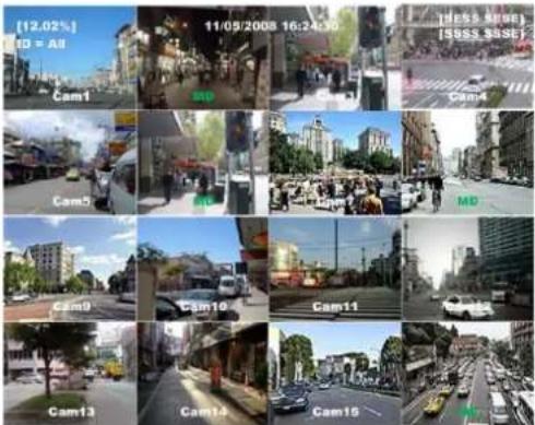
- Once it finishes booting up, the default 16 channel split-screen is displayed (9 channel split-screen for SVR-960C/945, 4 channel split-screen for SVR-480).
※ If a password for the unit has been set, the password input dialog is displayed.
text_image
(12.02%) ID = All Cam1 MD Cam4 MD Cam5 MD Cam9 Cam10 Cam11 Cam13 Cam14 Cam15 (HSS RIVE) [SSS SSSE]4.2 Single Display Full Screen
. Press a channel button or left-click.
- Press the [MULTI] button or left-click once again to go back to the split-screen.
4.3 Multi Display
. To watch multiple channels simultaneously, press the [MULTI] button
or the button from the Function

text_image
[12.02%] 16:05 23:00 - 18:24.30 9:00:35 S###1 7:00:35 S###1 Cammenu and click split mode.
- Each press of the [MULTI] button toggles between 4A, 4B, 4C, 4E, 9A, 9B, 10A and 16 channel split-screen modes. The SVR-960C/945 supports 4A, 4B, 4C, 4E, 9A and 9B, SVR-480 supports 4A.
4.4 Auto Sequencing
To go into auto sequencing mode, set 1 to 16 in the auto sequencing setup or set the desired
channels and then press the [AUTO] button on the front or the button from the Function
menu. To stop this feature, press the button again or click Auto to toggle it in the Function menu.
4.4.1 Default System Mode
Use

button to automatically convert the set channels.
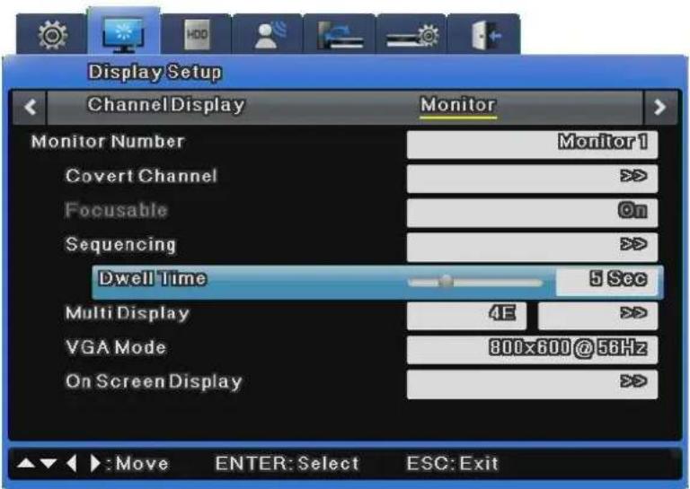
- Press the [MENU] button to set the dwell time. Alternately, click the button on the Function menu.
Go to "Display Setup" on the OSD menu.
Go to the "Monitor" submenu under "Display Setup" and press the [Enter] button or left-click. - Select "Dwell Time" and set a value between 1 and 60 seconds. When this is set to Off, auto sequencing will not work.
text_image
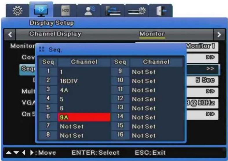
Display Setup Channel Display Monitor Monitor Number Monitor 1 Covert Channel >> Focusable On Sequencing >> Dwell Time 5 Sec Multi Display 4E >> VGA Mode 800x600 @ 56Hz On Screen Display >> : Move ENTER: Select ESC: Exit- Selecting "Auto Sequencing" brings up an option to select channels or split screens for the sequencing order, as shown in the picture below.
text_image
Display Setup Channel Display Monitor Seq. Seq Channel Seq Channel 1 1 9 Not Set 2 16DIV 10 Not Set 3 4A 11 Not Set 4 5 12 Not Set 5 6 13 Not Set 6 9A 14 Not Set 7 Not Set 15 Not Set 8 Not Set 16 Not Set Monitor1 >>> >>> 5 See >>> B@60Hz >>> Move ENTER: Select ESC: Exit- Auto sequencing mode can be enabled by pressing the [AUTO] button in all split modes.
- To exit auto sequencing mode, press the [AUTO] button once again.

- Up to 16 user modes can be defined.
- In the image above, 6 sequences are defined with single screen (1) → full screen (16DIV) → 4 channel split-screen (4A) → single screen (5) → single screen (6) → 9 channel split-screen (9A) all being displayed in sequence.
The SVR-960C/945 support 9, SVR-480 supports 4 channel split-screen.
4.4 Event Screen
You can set an event screen to automatically pop up.
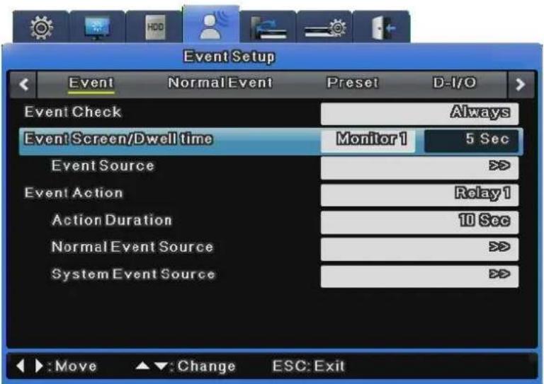
text_image
Event Setup Event Normal Event Preset D-I/O Event Check Always Event Screen/Dwell time Monitor1 5 Sec Event Source > Event Action Relay1 Action Duration 10 Sec Normal Event Source > System Event Source > :Move Change ESC: Exit- The Event Screen can be set for each monitor.
- To set the dwell time for each event popup, select a monitor and set the dwell time for the monitor.
- You can select events to pop up at Event Source. 3 types of event are available at Event Source: Sensor, Motion Detection, and Text.
- When events occur in several channels simultaneously, the screen automatically splits into that number of channels. For example, if events occur in 3 channels, event images are displayed on the 4 channel split-screen. To return to the previous screen, press one of the channel buttons.

-
If Event Screen is set to Off, event popups will not work.
-
If Event Screen is set to On, the popup image remains displayed until a button is pressed. To return to the previous screen, press any button.
4.5 Zoom In

- To zoom in on an image, press the [FUNC] button in single display full screen mode, select the 🔒 button, select the + button, and press the [Enter] button or left-click.
- When the button is selected, the default location is the center of the screen. When an image is zoomed in on, it can be moved 18 levels horizontally and 12 levels vertically.
- Use the navigation keys to move the image.
- To return to the previous screen, select the – button and then press the [Enter] button or left-click.
4.6 Live Video Pause
- You can pause a live video feed.
- Press the [PAUSE] button to pause a live video, and press the button again to resume the live feed.
4.7 PTZ Control
You can control PTZ while watching a video in real time by connecting the PTZ controller with the DVR and setting the protocol from the "Serial" menu.
You can either press the PTZ button on the front or press the [Func] button to execute PTZ.
To control PTZ operation, first select a channel. The selected channel will be outlined in blue.
Available PTZ and keyboard models are as shown below.
Channel 1
P/T Z/F Menu
Preset 1
Load Save
Aux 1
On Off
| Model Maker | |
| SDZ160/330, Samsung SPDKeyboard SCC3000, Samsung SRX-100B | SAMSUNG TECHWIN |
| BOSCH AutoDome, TC8560X-4 BOSCH | |
| PELCO (P), PELCO (D) PELCO | |
| Honeywell 755/655, HRX-2000, ScanDome2 HONEYWELL | |
| Sony EVI-D3x SONY | |
| VT VPT-4x VT | |
| AD SpeedDome AD | |
| SungJin SJ372R1' SUNGJIN | |
| Samsung SCC641 SAMSUNG ELECTRONICS | |
| Panasonic WV-CS850 PANASONIC | |
| LG GAC-PT2 | LG |
| Keyboard KBD300A, WGI SPD1800/2600 | WEBGATE Inc. |
| Merit-Lilin FastDome | MERIT |
| Elmo PTC200C | ELMO |
| Canon VC-C4 | CANON |
| HTC-230S | D-MAX |
| RVision | RVISION |
| Elbex | ELBEX |
| VIDO | VIDO |
| VICON | VICON |
| Hunt | HUNT |
| ORX-1000 | SYSMANIA |
| Fine CRR-1600 | LIVEI |
| Tokin | a |
| Kodicom KRE KODICOM | |
| Nuvico | NUVICO |
- Press a channel button.
- Press the [PTZ] button on the front or click the button on the Function menu.
- The PTZ menu (Pan/Tilt, Zoom/Focus, Load Preset, Save Preset) will appear.
- Select the desired menu item and then press the [Enter] button or click.
4.7.1 Pan/Tilt
This menu item is used for real-time Pan and Tilt monitoring.
Select Pan/Tilt in PTZ mode.
To use pan the camera, press the left or right arrow key on the front or click on the left or right of the screen. To tilt the camera, press the up or down arrow key on the front or click on the top or bottom of the screen.
4.7.2 Zoom/Focus
This menu item is for real-time Zoom and Focus monitoring.
Select Zoom/Focus in PTZ mode.
. Use the navigation keys on the front or the mouse wheel to use Zoom and Focus.
4.7.3 Load Preset
This menu item is used to go to a preset location in the real-time monitoring mode.
. Use the up or down arrow key or the mouse wheel to select a preset number.
- Select Load and then press the [Enter] button or click.
4.7.4 Save Preset
This menu item is for setting a new preset location in the real-time monitoring mode.
Use the Pan/Tilt and Zoom/Focus menu items to adjust the camera position.
Use the up or down arrow key or the mouse wheel to select a preset number.
- Select Save and then press the [Enter] button or click.
4.7.5 Auxiliary On
This is used for special functions of a PTZ device in real-time monitoring mode.
Use the up or down arrow key or the mouse wheel to set an Aux number.
- Select On and then press the [Enter] button or click.
- Up to 16 Aux numbers can be set.
4.7.6 Auxiliary Off
This is to stop special functions of a PTZ device.
Use the up or down arrow key or the mouse wheel to set an Aux number.
. Select Off and then press the [Enter] button or click.
4.7.7 Menu
This is used to enter the console menu of the connected PTZ device. The console menu can be set with the navigation keys and the [Enter] button on the front.
After settings are done, press the [ESC] button or the [PTZ] button on the front to exit the console menu (available only with the Samsung SPD protocol).
Chapter 5. Playback
5.1 Playback Mode
5.1.1 Playback on Default Display (16/9/4 channel split-screen)
- Press the [PLAY] button or click the ▶ button on the Function menu in monitoring mode.
- Press the [PLAY] button or the [FWD] button to play a video at the default 1x speed.
- Press the [REW] button to play a video in reverse at the default 1x speed.

Press the [Play] button in monitor split mode to play videos from 16/9/4 channels.
5.1.2 Playback
PLAY
: Play a video at 1x speed. When using a mouse, click the button in the Function menu. Pressing the [PLAY] button in monitor mode always plays multiple videos. Also, pressing the [PLAY] button plays recorded videos from the last playback timestamp.
PAUSE
: Pause video playback. When using a mouse, click the button in the Function menu.
STOP
: Stop video playback. When using a mouse, click the button in the Function menu.
FWD
: Each press of this button changes the playback speed (in the order of x1, x2, x4, x8, x16, x32, x64, x1/2, x1, x2 and x4). Pressing the [FWD] button while viewing a live feed plays the video recorded 1
minute before the current live time. Pressing the 🎨 button on the Function menu also changes the playback speed.
REW
: Each press of this button changes the reverse playback speed (in the order of x1, x2, x4, x8, x16, x32, x64, x1/2, x1, x2 and x4). Pressing the [REW] button while viewing a live feed plays the video in reverse from the last recorded frame. Pressing the 📋 button on the Function menu also changes the playback speed.
STEP FORWARD : Pressing the [FWD] button while paused plays the video frame by frame. Press the [PLAY] button to return to normal playback.
STEP REWIND : Pressing the [REW] button while paused plays the video frame by frame in reverse. Press the [PLAY] button to return to normal playback.
1/2 REWIND
: Press the 2 button on the Function menu to play the video at 1/2x speed.
1/2 FORWARD
: Press the 12 button on the Function menu to play the video in reverse at 1/2x speed.
5.2 Search Mode
This menu item is used to search by time or log to play data at a specific time.
Search mode includes Time, Calendar, Event and Thumbnail.
To go into search mode, press the [Search] button on the front or click the [Search] button on the Function menu.

flowchart
graph TD
    A["SEARCH"] --> B["Time"]
    A --> C["Calendar"]
    A --> D["Event"]
    A --> E["Thumbnail"]
5.2.1 Time Search
Enter a desired date and time and select Search to go to the video at the specified date and time.
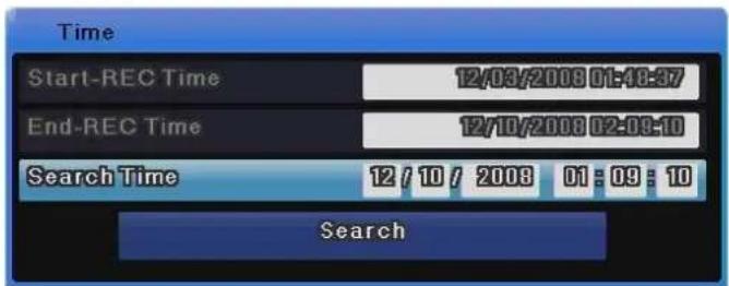
text_image
Time Start-REC Time 12/03/2008 01:48:37 End-REC Time 12/10/2008 02:08:10 Search Time 12 / 10 / 2008 01 : 09 : 10 SearchStart-REC Time : Displays the date and time when the recording started. End-REC Time : Displays the date and time of the latest recording. Search Time : Select desired date and time between the recording start time and
the end time.
Search Button
: Search the video for the specified date and time.
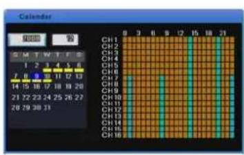
5.2.2 Calendar Search
You can search videos more easily with the calendar.
The following pictures are status screens that are selected with year, date, and time.
text_image
Calendar 星期 部 S M T W T F G 1 2 3 4 5 6 7 8 9 10 11 12 13 14 15 16 17 18 19 20 21 22 23 24 25 26 27 28 29 30 31 CH1 CH2 CH3 CH4 CH5 CH6 CH7 CH8 CH9 CH10 CH11 CH12 CH13 CH14 CH15 CH16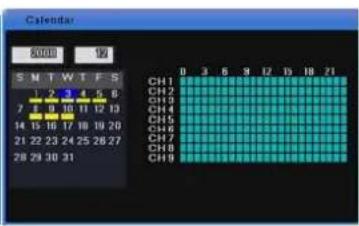
text_image
Calendar 20:00 19 S M T W T F S 1 2 3 4 5 6 7 8 9 10 11 12 13 14 15 16 17 18 19 20 21 22 23 24 25 26 27 28 29 30 31 CH1 CH2 CH3 CH4 CH5 CH6 CH7 CH8 CH9 0 3 5 9 12 15 18 21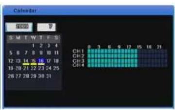
text_image
Calendar S M T W T F S 1 2 3 4 5 6 7 8 9 10 11 12 13 14 15 16 17 18 19 20 21 22 23 24 25 26 27 28 29 30 31 CH1 0 3 6 9 12 15 18 21 CH2 CH3 CH4For the SVR-3200, Monitor 1 displays the recording status from channel 1 to 16 while Monitor 2 displays from channel 17 to 32.
Clicking on the hourly recording section displays the minute status.

text_image
Calendar CH1 CH2 CH3 CH4 CH5 CH6 CH7 CH8 CH9 CH10 CH11 CH12 CH13 CH14 CH15 CH16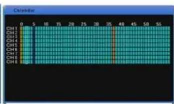
text_image
Calendar CH1 0 5 10 15 20 25 30 35 40 45 50 55 CH2 CH3 CH4 CH5 CH6 CH7 CH8 CH9 CH1 High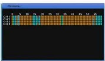
text_image
Chenius CH1 CH2 CH3 CH4Year : Select a year. You can use the mouse wheel to change the year.
Month : Select a month. You can use the mouse wheel to change the month.
Date : Go to the calendar, select the desired date and press the [Enter] button. You can use the mouse wheel to search by time.
Time : Select a time period and press the [Enter] button to start playback. When using a mouse, select the time and use the mouse wheel to play the video at the specified time.
Minute : Displays saved video data by minute. To play, select a minute, and then press Enter. When using the mouse, select a minute, and then use the mouse wheel to play the video.
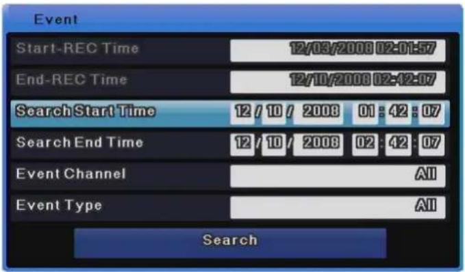
5.2.3 Event Search
You can specify a time period and search all channels, some channels, all events, motion
detection or sensors. Use the up or down arrow key on the front to change the date and time. Alternately, select an item you want to change and use the mouse wheel to change it. The search results are displayed in a separate list in the event search result window. Select an item in the search list and press the [Enter] button or use the mouse wheel to go to the specified date and time and start playback.
text_image
Event Start-REC Time 12/03/2008 02:01:57 End-REC Time 12/10/2008 02:12:07 Search Start Time 12 / 10 / 2008 01 : 42 : 07 Search End Time 12 / 10 / 2008 02 : 42 : 07 Event Channel All Event Type All SearchStart-REC Time : Display the date and time when the recording started.
End-REC Time : Display the date and time of the latest recording.
Search Start : Enter a start date and time to start the search from. Use the navigation buttons to go to an item, press the [Enter] button and use the up or down arrow key to change the value. When using mouse, click an item and use the mouse wheel to change the value.
Search End Time : Enter an end date and time to search until. Use the navigation buttons to go to an item, press the [Enter] button and use the up or down arrow key to change the value. When using a mouse, click an item and use the mouse wheel to change the value.
Event Channel : Select a channel. For the SVR-3200, Ch1 \~ Ch32 are available. For the SVR-1680C/1660C/1645, Ch1 \~ Ch16 are available. For the SVR-960C/945, Ch1 \~ Ch9 are available. For the SVR-480 Ch1\~Ch4 are available.
Event Type : Select an event type. You can select all events, motion detection, video loss or text.
5.2.4 Thumbnail Search
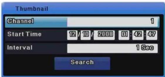
Use the up or down arrow key on the front or the mouse wheel to a specify time and search a specific channel at regular intervals. The search results are displayed in thumbnails. Select a thumbnail to go to the specified date and time and start playback.
text_image
Thumbnail Channel 1 Start Time 12/10/2008 01:42:47 Interval 1 Sec Search| Channel | : Select a channel. Use the up or down arrow key on the front or the mouse wheel to change the value. |
| Start Time | : Enter a start date and time to start the search from. Use the left or right arrow key to go to an item, press the [Enter] button and use the up or down arrow key or the mouse wheel to change the value. |
| Interval | : Search in a specific interval and display the result. Use the up or down arrow key or the mouse wheel to change the value. |
| View Video | : Press the [Search] button to display 16 videos in the specified interval based on the start time. Press the [Func] button or use the mouse wheel to return to the search window. |
| Select Video | : Click a video thumbnail and play it from the specified time. Press the [Enter] button or click to play the video. |

Changing the I-frame duration may produce results different from your expectation from Thumbnail Search.
5.3 Copy
This menu item is used to copy a recorded video. There are three types of copy: CD/DVD, RE4 and AVI. To use the Copy function, you must change your permissions in the Security settings.
For more information about changing permissions, please refer to section 6.9.3 on Security. To
copy, press the [COPY] button on the front or click the button on the Function menu.
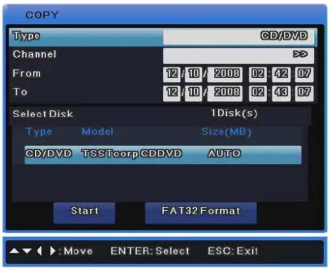
5.3.1 CD/DVD
The CD/DVD type uses a CD or DVD to copy a video and detects the CD or DVD automatically.
text_image
COPY Type CD/DVD Channel From 12 / 10 / 2008 02 : 42 : 07 To 12 / 10 / 2008 02 : 43 : 07 Select Disk 1Disk(s) Type Model Size(MB) CD/DVD TSSTcorpCDDVD AUTO Start FAT32 Format :Move ENTER: Select ESC: Exit
The SVR-945 is not equipped with a DVD device so you must connect the unit with an external backup device. Connect an external backup device to the USB or eSATA port, execute copy and select CD/DVD. On the media list, a CD/DVD device whose type is [Ext] is displayed. Select the device and make a copy in the same way as other models.
| Type | : Select CD/DVD. Use the up or down arrow key on the front or the mouse wheel to select it. Press the [Enter] button and use the up or down arrow key on the front or the mouse wheel to change the value. |
| Channel | : You can select some or all of the 16 channels. Select the channel field and press the [Enter] button or use the mouse wheel to select a channel. |
| From | : Enter the start date and time for copying. Use the up or down arrow key or the mouse wheel to set the value. |
| To | : Enter the final date and time for copying. Use the up or down arrow key or the mouse wheel to set the value. |
| Select Disk | : Select the media to copy. Select the Select Disk field and press the [Enter] button to select the media. |
| Start | : Start copying. Move to the [Start] button and press the [Enter] button or left-click. |
| FAT32 Format | : Format a USB disk or HDD in FAT32.Do not use this for CD/DVD copying. When using media, you need to format it first. Select the [FAT32 Format] button and press the [Enter] button or left-click. |
For more information on support media, refer to the table below.
| DVD-R Maker CD-R Maker | |
| Mitsubishi (16x recommended) Mitsubishi (16x recommended) | |
| TDK (16x recommended) TDK (16x recommended) | |
| Imation (16x recommended) Imation (16x recommended) | |
| Sony (16x recommended) Sony (16x recommended) |
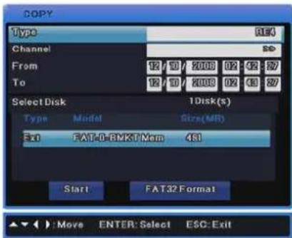
5.3.2 RE4
text_image
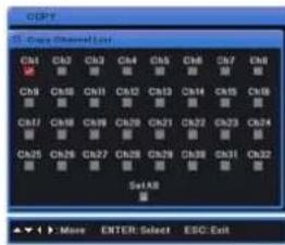
COPY Type REJ Channel SD From 12 / 10 / 2008 02 : 42 : 27 To 12 / 10 / 2008 02 : 43 : 27 Select Disk 1Disk(s) Type Model Size(MR) Red FAT-0-BMKT Mem 4S1 Start FAT32 Format :Move ENTER: Select ESC: ExitYou can back up videos using HDD or USB storage. You can play them using the mini player or network manager. Select the channel field and use the [Enter] button or the mouse wheel to open the channel list as shown below.
text_image
CPU C01 C02 C03 C04 C05 C06 C07 C08 C09 C10 C11 C12 C13 C14 C15 C16 C07 C08 C09 C10 C11 C12 C13 C14 C15 C16 C05 C06 C07 C08 C09 C10 C11 C12 C13 C14 C15 C16 Set All ► More ENTER: Select ESC Exit[SVR-3200]
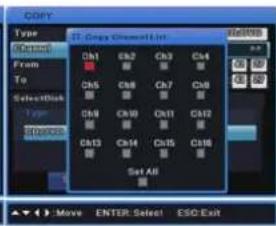
text_image
COPY Type From To Select Disk Type Ch1 Ch2 Ch3 Ch4 Ch5 Ch6 Ch7 Ch8 Ch9 Ch10 Ch11 Ch12 Ch13 Ch14 Ch15 Ch16 Set All Move ENTER: Select ESC Exit[SVR-1680C/1660C/1645]
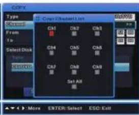
text_image
COPY Type Content From To Select Disk To COMPOS Copy/ShowAll List CM1 CM2 CM3 CM4 CM5 CM6 CM7 CM8 CM9 Set All More ENTER: Select ESC: Exit[SVR-960C/945]
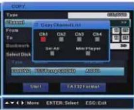
text_image
copy Type 60A0098 Format From To Baudmets Select Disk CH1 CH2 CH3 CH4 Set All Main Player B01020: TextPage:80100 A0102 Start EA132 Format More ENTER: Select ESC Exit[SVR-480]
| Type | : Select RE4. Use the up or down arrow key or the mouse wheel to select it. |
| Channel | : Select the channel field and press the [Enter] button or use the mouse wheel to pop up the channel list. |
| Select Channel | : You can select some or all of the channels. Select a channel on the channel list and press the [Enter] button or left-click. |
| From | : Enter a start date and time for copying. Use the up or down arrow key or the mouse wheel to set a value. |
| To | : Enter the final date and time for copying. Use the up or down arrow key or the mouse wheel to set a value. |
| Select Disk | : Select a media to copy. Select the Select Disk field and press the |
[Enter] button or click to select a media.
Start
: Start copying. Move to the [Start] button and press the [Enter] button or left-click.
FAT32 Format
: Format unformatted USB storage devices or HDDs in FAT32 before copying. Select the [FAT32 Format] button and press the [Enter] button or left-click.

A backup file that is not 100% complete cannot play on a PC properly.
5.3.3 AVI
This type is used to copy a part of a selected channel using USB or HDD storage.

text_image
COPY Type AVI Channel 1 From 12/10/2008 02:42:27 Duration 10 Sec Select Disk 1Disk(s) Type.Model Size(MB) Ext FAT-0-BMKT Mom 491 Start FAT32 Format ►:Move ENTER: Select ESC: Exit| Type | : Select AVI. Use the up or down arrow key or the mouse wheel to select it. |
| Channel | : Select a channel. Use the up or down arrow key or the mouse wheel to select it. |
| From | : Enter the start date and time for copying. Use the left or right arrow key to move between the items and use the up or down arrow key to change the time and date. When using a mouse, left-click an item and use the wheel to change the value. |
| Duration | : Specify the duration for copying. Make a copy only for the specified duration. Use the up or down arrow key or the mouse wheel to specify it. |
| Select Disk | : Select a media to copy. Select the Select Disk field and press the |
[Enter] button or click to select media.
Start
: Start copying. Move to the [Start] button and press the [Enter] button or left-click.
FAT32 Format
: Format unformatted USB storage devices and HDDs in FAT32 before copying. Select the [FAT32 Format] button and press the [Enter] button or left-click.

If the copied file does not play on a PC, install the unified codec pack.
Chapter 6. Setup
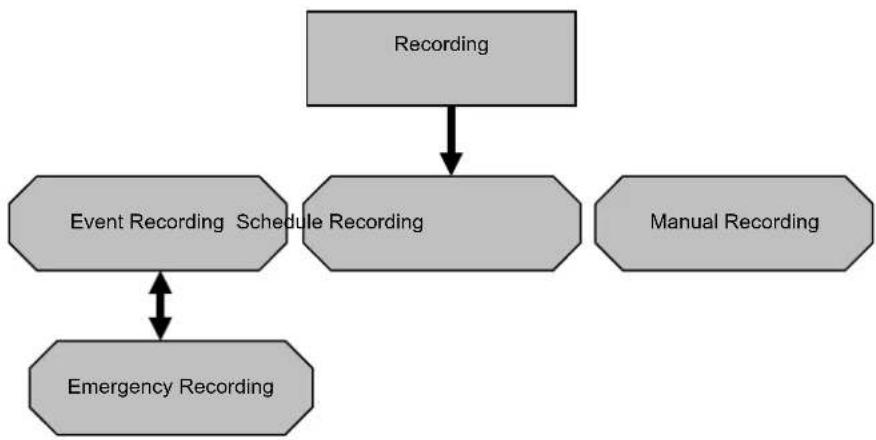
6.1 Record Setup
There are 4 DVR recording modes. Their relationship is as shown in the image below, which briefly describes recording modes.
For more information on recording, refer to the following sections.
flowchart
graph TD
    A["Recording"] --> B["Event Recording Schedule Recording"]
    B --> C["Emergency Recording"]
    B --> D["Manual Recording"]
6.2 Time Setup
You need to set the system time before setting recording.
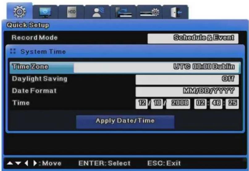
text_image
Quick Setup Record Mode Schedule & Event System Time Time Zone UTC 00:00 Dublin Daylight Saving Off Date Format MM/DD/YYYY Time 12 / 10 / 2008 02 : 48 : 25 Apply Date/Time Move ENTER: Select ESC: ExitSetting the time based on your location is very important for the protection of recorded data. It is
not recommended to change the time while recording.
The factory default time zone is UTC 00:00 Dublin.
6.2.1 How to Set Time

If you change the time when recording is already in progress, the time is also changed for existing recorded videos. It is recommended to back up critical video data before changing the time.
- Press the [MENU] button on the front or the button on the Function menu.
- Go to the "Quick Setup" menu.
- Select "Time" from "Quick Setup". Use the [Enter] button or the mouse wheel to select it.
- If you press the buttons in the proper order, the image in 6.2 Time Setup appears.
- Use the navigation keys or the mouse to move to each submenu and press the [Enter] button or click.
Time Zone
Use the left or right arrow key on the front or the mouse wheel to select your time zone. Each press of the arrow keys changes the time zone. (To go to the previous menu, press the [ESC] button on the front or right-click. This is the same for all OSD menus.)
Daylight Saving
(1) When selecting a Daylight Saving Time zone, Daylight Saving automatically changes to On, and is Off for other time zones.
(2) To customize the start and end time of DST, use the [◀/▶] buttons and change Daylight Saving to Custom.
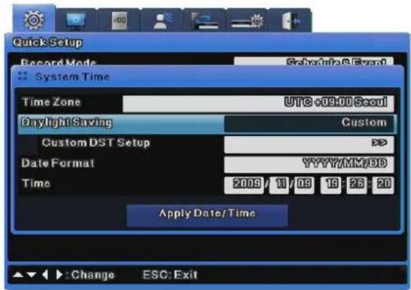
text_image
Quick Setup Record Mode Schedule Event System Time Time Zone UTC +09:00 Seoul Daylight Saving Custom Custom DST Setup Date Format YYYY/MM/DD Time 2009 11/09 19 25 20 Apply Date/Time Change ESC: Exit(3) Changing Daylight Saving to Custom displays the Custom DST Setup options.
Upon clicking on Custom DST Setup, two setup methods display.
The first is for selecting a month and date to define the start and end times of DST.
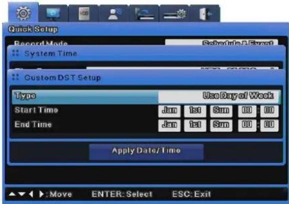
text_image
Quick Setup Record Mode System Time Custom DST Setup Type Use Day of Work Start Time Jan 1st Sun 00 00 End Time Jan 1st Sun 00 00 Apply Date/Time Move ENTER: Select ESC: ExitThe second is for selecting a month, week, and day to define the start and end times of DST.
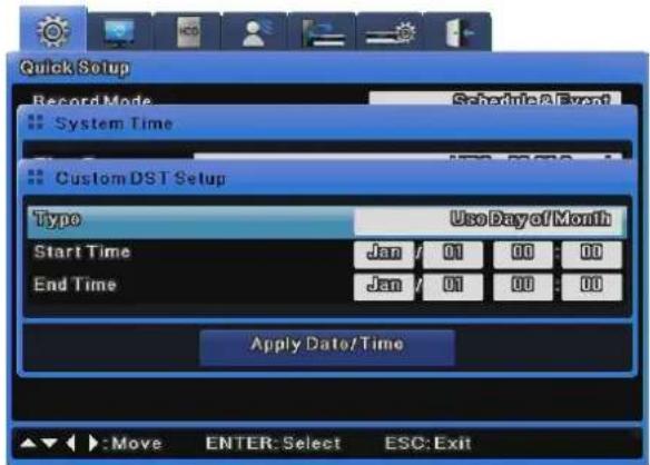
text_image
Quick Setup Record Mode Schedule A Event System Time Custom DST Setup Type Use Day of Month Start Time Jan / 01 00 : 00 End Time Jan / 01 00 : 00 Apply Date/Time :Move ENTER: Select ESC: Exit
For more information on NTP, refer to "NTP" of Network Setup.
Date Format
Select the date format. Use the left or right arrow key or the mouse wheel to select "MM/DD/YYYY", "YYYY/MM/DD" or "DD/MM/YYYY".
Time
Use the left or right arrow key to move between year, month, date and time. Use the up or down arrow key or the mouse wheel to set each item.
Apply
You must press the [Apply] button to save the Date/Time values. Then, the dialog box below appears.
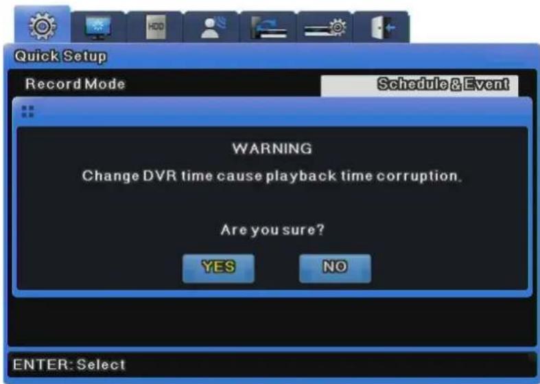
text_image
Quick Setup Record Mode Schedule & Event WARNING Change DVR time cause playback time corruption. Are you sure? YES NO ENTER: Select
Setups other than "Date/Time" setup are automatically recorded if the menus are completely closed, but "Date/Time" setup is not automatically recorded because it may damage the HDD recording file system. Be sure to press the [Apply] button to apply changes.
6.3 Camera Setup
This menu is used to set the conditions of each camera connected to the unit.
You can use the camera setup menu to adjust [Title], [Status], [Color], [AGC], [Brightness], [Contrast] for each of the connected cameras. The set values apply to monitoring and search in the same way.
For more information on each menu item, refer to the following sections.

NTSC and PAL cameras cannot be used for the unit at the same time. For example, you cannot connect NTSC cameras to 1CH to 5CH while connecting PAL cameras to 6CH to 16CH. Also, when replacing NTSC cameras with PAL cameras, you must reboot (power on/off) the unit after connecting the PAL cameras for proper recognition.
The set values apply to monitoring and search in the same way.
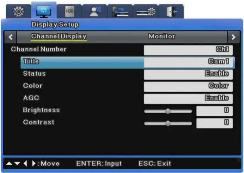
text_image
Display Setup Channel Display Monitor Channel Number Ch1 Title Cam1 Status Enable Color Color AGC Enable Brightness 0 Contrast 0 Move ENTER: Input ESC: Exit6.3.1 How to Set a Camera
Press the [MENU] button and use the navigation keys or the mouse wheel to select a desired channel from the "Channel" menu under the "Display" menu of Display Setup.
Title
Specify the camera name.
Press the [Enter] button or click to open the character input menu.
When inputting a string, the character input window appears.
The character input window may differ depending on the menu, but the character input method is the same.

text_image
A B C D E F G H I J K L M N O P Q R S T U V W X Y Z ← a b c d e f g h i j k l m n o p q r s t u v w x y z → . ( ) < > * - + = / [ ] @ ? ! 0 1 2 3 4 5 6 7 8 9 Enter← Cam1. Use the navigation buttons to input characters.
. When using a mouse, click a character.
. Press the navigation buttons to select characters.
After selecting characters, press the [Enter] button to input them.
. To delete characters, press the [←] button to move back.
. To insert a space between characters, press the [→] button to insert a space.
Channel Status
You can enable or disable a camera.
Press the [Enter] button and use the left or right arrow key or the mouse wheel to select "Enable" or "Disable".
To increase recording or network monitoring speed, be sure to disable unused channels.
Color
Press the [Enter] button and use the left or right arrow key or the mouse button to select "Color" or "B/W".
AGC (Auto Gain Control)
AGC is used to automatically control the input range of video signals from a camera.
Press the [Enter] button and use the left or right arrow key or the mouse wheel to select "Enable" or "Disable".
Brightness / Contrast
You can adjust the brightness and contrast of a video.
Press the [Enter] button and use the left or right arrow key or the mouse wheel to select a value between "-9" and "+9".
6.4 Monitor Setup
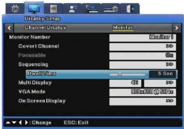
This menu is used to set related items when displaying a video on the monitor.
text_image
Display Setup Channel Display Monitor Monitor Number Monitor 1 Cover1 Channel >> Focusable On Sequencing >> Dwell Time 5 Sec Multi Display 42 >> VGA Mode 900x600 @ 56Hz On Screen Display >> : Change ESC: ExitMonitor 1 & Monitor 2\~4 (SVR-3200/1680C/1660C)
Monitor 1 is available for all supported functions of the DVR while Monitor 2\~4 are available for all functions other than playback and search.
The SVR-3200, however, uses Monitor 2 just like Monitor 1, allowing monitoring and playing channels from 17 to 32.
Monitor 1 & Monitor 2 (SVR-1645/960C/945)
Monitor 1 is available for all supported functions of the DVR while Monitor 2 is available for event popup, user sequencing and split screen.
Covert Channel
This menu is used to hide channels in live mode.
The Covert Channel menu shows the unit's channel list. Press the [Enter] button or click to select a channel. The selected channels then do not show videos in live/playback modes.
Focusable
This option is for eliminating unnecessary focusing movements in monitors other than Monitor 1, when they are not in use.
When turning Off the Focusable option for Monitors 2 to 4 (Spot Monitors), the focus function remains in Monitor 1 and is not available in Monitors 2 to 4 when the Monitor button is pressed.
When Focusable is disabled, monitors cannot be used for any function other than displaying the Live screen.
When Monitor 3's Focusable is Off, the focus function is only available in Monitors 1, 2 and 4.
Auto Sequencing
This is for editing the auto sequencing function. The 16 available sequencing modes have a dwell time between 1 and 60 seconds.
Multi Display
This menu is used to define the multi display of 4E (4 channels), 9B (7 channels) or 10A (10 channels) in advance. For the SVR-960C/945, only 4E (4 channels) can be defined.
To set multi display, select the target and the window on its right, use the [Enter] button or the mouse wheel to open the window, and press the [Enter] button or click to select a channel. Then, press the [ESC] button or right-click.
※ SVR-480 does not support to set multi display.
VGA Mode
Three VGA modes are provided for VGA monitors. The available modes are 800x600, 1024x768 and 1280x1024.
On Screen Display
This determines what information is displayed for live video feeds or video playback.
For live video feeds, you can set the time, channel name, event, recording status, HDD, remote control ID and text. For video playback, you can set the time, command, channel name, event and text display.
6.5 Record Setup
Three different recording options are available: Schedule Recording, Manual Recording, and Event Recording. Schedule Recording records video automatically at a scheduled time. Manual Recording enables you to record video manually by pressing the "REC" button. Event Recording records video when an event occurs if the Program and Event Check settings are activated.
6.5.1 Program Setup
Using the [Program] menu, you can set up a program to use for both Manual & Event and Schedule & Event. You can adjust the frame rate, video quality and resolution of the program.
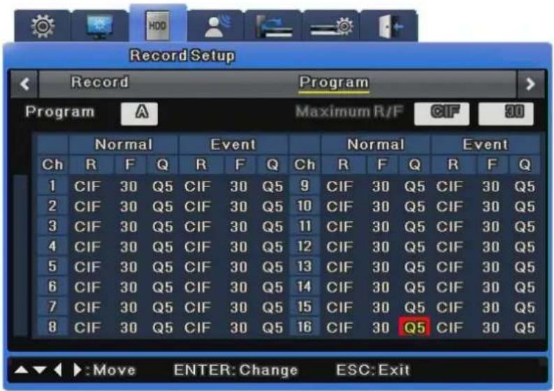
text_image
Record Setup Record Program Program A Maximum R/F CIF 30 Normal Event Normal Event Ch R F Q R F Q Ch R F Q R F Q 1 CIF 30 Q5 CIF 30 Q5 9 CIF 30 Q5 CIF 30 Q5 2 CIF 30 Q5 CIF 30 Q5 10 CIF 30 Q5 CIF 30 Q5 3 CIF 30 Q5 CIF 30 Q5 11 CIF 30 Q5 CIF 30 Q5 4 CIF 30 Q5 CIF 30 Q5 12 CIF 30 Q5 CIF 30 Q5 5 CIF 30 Q5 CIF 30 Q5 13 CIF 30 Q5 CIF 30 Q5 6 CIF 30 Q5 CIF 30 Q5 14 CIF 30 Q5 CIF 30 Q5 7 CIF 30 Q5 CIF 30 Q5 15 CIF 30 Q5 CIF 30 Q5 8 CIF 30 Q5 CIF 30 Q5 16 CIF 30 Q5 CIF 30 Q5 ▲▼◀ ▶:Move ENTER: Change ESC: ExitTwo choices are available: 1) Select a program by the frame rate, quality, and resolution, or 2) Set up a program manually. For Event Recording, you can select a frame rate up to the maximum possible for one channel. When events occur simultaneously in more than two channels, the recording frame rate may be automatically adjusted.
Program
Under the Program menu, a total of 26 programs labeled from A to Z are available for you to define with the recording resolution and quality for each channel. For more information about the setting values of the Program menu, please refer to section 3.5.
Ch (Channel)
Indicates a channel number.
R (Resolution)
Indicates the recording resolution. A total of three types are available: D1 (704x480), Half D1 (704x240), and CIF (352x240).
F (fps)
Indicates frames per second: from 1 to 30fps. The maximum frame rate may vary depending on settings.
Q (Quality)
Indicates the recording quality: Q5, Q4, Q3, Q2, and Q1. For Event Recording, Q3 or higher is recommended.
Max R/F
Indicates the maximum frame rate available for a selected resolution. For instance, CIF 30fps means that you can select up to 30fps for the CIF resolution of a selected channel. D1 30fps means that you can select up to 30fps for the D1 resolution.
How to Calculate Recording Performance
$$ D 1 [ 7 0 4 \times 4 8 0 ] = 2 \times \text { Half } D 1 [ 7 0 4 \times 2 4 0 ] = 4 \times \text { CIF } [ 3 5 2 \times 2 4 0 ] $$

120 D1 compressed frames = 240 Half D1 compressed frames = 480 CIF compressed frames

The resolution and maximum frame rate vary depending on the number of enabled channels.
- When disabling a channel in the Channel settings
How to Disable: Select Menu > Camera Settings > Use Channel > Disable. (The channel is then grayed out to show that it is disabled.) For example, the SVR-1660C can record every channel at up to CIF 30fps. If a channel is "Disabled" in the Channel settings, there is then a surplus of CIF 30fps recording capacity. You can use the —surplus CIF (352x240) 30fps to increase another channel's resolution to Half D1 (704x240) 30fps (remember from above that CIF x 2 = Half D1).
- Setting a channel's frame rate to "0fps" in the Program settings
Surplus CIF 30fps cannot be used to increase another channel's resolution because the 0fps channel still uses at least 2 to 3 recording frames per second for various reasons including network communications. You must disable the channel instead of setting it to
0fps if you want to conserve and use the surplus CIF 30fps recording capacity for another channel.

Relation Between Normal Recording and Event Recording
When an event occurs, Event Recording is activated with the Program settings. DVR recording performance varies depending on the model. For example, the recording performance of the SVR-1660C is CIF 480fps for both Normal and Event Recording. When both recording modes are in effect, its recording performance cannot exceed CIF 480fps. That means that Event Recording can be set up for the SVR-1660C only if the total of Event and Normal Recording of all channels does not exceed CIF 480fps.
• Event Settings in and CIF 480fps Recording Performance
When every channel is set up to record normally at CIF 30fps, the Event Recording settings of for 1^st channel are limited to CIF 30 fps, Half 15 fps, and D1 7fps. If you want to set the Event Recording settings value to D1 30fps, the Normal Recording settings value of the other channels must be changed to total CIF 360fps or less.
- When Events Occur in Multiple Channels Simultaneously
When events occur simultaneously in multiple channels and the Event Recording settings value exceeds the DVR's maximum recording performance, the Normal Recording settings value is retained, and the channels with events drop their Event Recording frame rates settings to record the events.

The SVR-1680C provides D1 30 compressed frames for all channels; it can record programs at a manually selected resolution and frame rate at all times.
Quick Record Setup (Quick Setup)
Quick Setup provides recording, language, time and audio setups in one place.
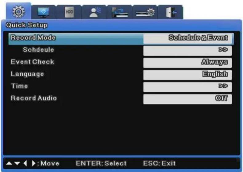
text_image
Quick Setup Record Mode Schedule&Event Schedule Event Check Always Language English Time Record Audio Off Move ENTER:Select ESC:ExitHow to Set Quick Recording
Select 'Quick Setup'.
Program Setup
All programs are set to 0fps by default so each program needs to be set individually (described in details in recording menu).
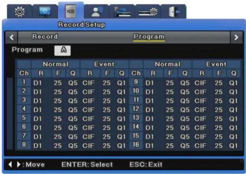
text_image
Record Setup Record Program Program A Normal Event Normal Event Ch R F Q R F Q Ch R F Q R F Q 1 D1 25 Q5 CIF 25 Q1 9 D1 25 Q5 CIF 25 Q1 2 D1 25 Q5 CIF 25 Q1 10 D1 25 Q5 CIF 25 Q1 3 D1 25 Q5 CIF 25 Q1 11 D1 25 Q5 CIF 25 Q1 4 D1 25 Q5 CIF 25 Q1 12 D1 25 Q5 CIF 25 Q1 5 D1 25 Q5 CIF 25 Q1 13 D1 25 Q5 CIF 25 Q1 6 D1 25 Q5 CIF 25 Q1 14 D1 25 Q5 CIF 25 Q1 7 D1 25 Q5 CIF 25 Q1 15 D1 25 Q5 CIF 25 Q1 8 D1 25 Q5 CIF 25 Q1 16 D1 25 Q5 CIF 25 Q1 ►: Move ENTER: Select ESC: ExitSchedule & Event Setup
Set record mode to "Schedule & Event" and set a schedule and event for each date and time.
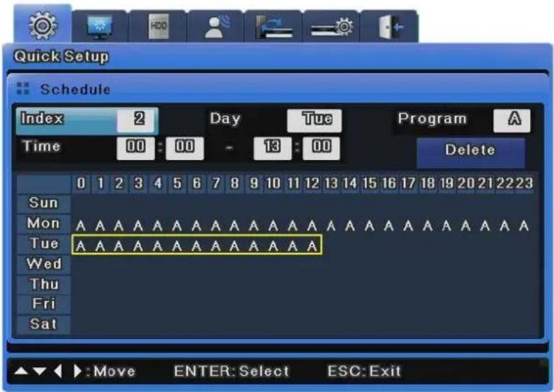
text_image
Quick Setup Schedule Index 2 Day Tue Program A Time 00:00 - 13:00 Delete Sun 0 1 2 3 4 5 6 7 8 9 10 11 12 13 14 15 16 17 18 19 20 21 22 23 Mon A A A A A A A A A A A A A A A A A A A A A A A A A A A A A A A A A A A A A Tue A A A A A A A A A A A A A A A A A A A A A A A A A A A A A A A A A A A A A A Wed \\n Thu Nu Nu Nu Nu Nu Nu Nu Nu Nu Nu Nu Nu Nu Nu Nu Nu Nu Nu Nu Nu Nu Nu Nu Nu Nu Nu Nu Nu Nu Nu Nu Nu Nu Nu Nu Nu Nu Nu Nu Nu Nu Nu Nu Nu Nu Nu Nu Nu Nu Nu Nu Nu Nu Nu Nu Nu Nu Nu Nu Nu Nu Nu Nu Nu Nu Nu Nu ,Nu Nu Nu Nu Nu Nu Nu Nu Nu Nu Nu Nu Nu Nu Nu Nu Nu Nu Nu Nu Nu Nu Nu Nu Nu Nu Nu Nu Nu Nu Nu Nu Nu N u.k.v.k.k.k.k.k.k.k.k.k.k.k.k.k.k.k.k.k.k.k.k.k.k.k.k.k.k.k.k.k.k.k.k.k.k.k.k.k.k.k.k.k.k.k.k.k.k.k.k.k.k.k.k.k.k.k.k.k.k.k.k.k.k.k.k.k.k.k.k.k.k.k.k.k.k.k.k.k.k.k.k.k.k.k.k.k.k.k.k.k.k.k.k.k.k.k.k.k.k.k.k.l →:Move BNTER:Select ESC:ExitHow to Check Recording

If record setup is properly completed, the 'REC LED' on the front will flicker. Also, [S] is displayed to show that currently all channels are recorded as scheduled.
6.5.2 Manual/Schedule Recording Setup
You can switch between Manual and Schedule Recording by changing the recording mode.
Both Manual and Schedule Recording enable you to choose a program to record. The resolution, frame rate, and quality may vary depending on the selected program.
Manual Recording
Manual Recording is activated only when the recording mode is set to Manual & Event. After selecting a program, press the [REC] button on the front of the DVR unit to begin recording. If you want to schedule a recording, switch the recording mode to Schedule & Event.
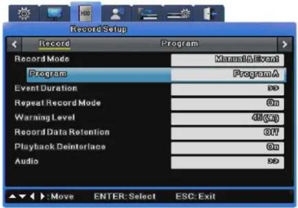
text_image
Record Setup Record Program Record Mode Manual&Event Program ProgramA Event Duration > Repeat Record Mode On Warning Level 45 (GS) Record Data Retention Off Playback Deinterlace On Audio > ▲▼ ▶:Move ENTER: Select ESC: Exit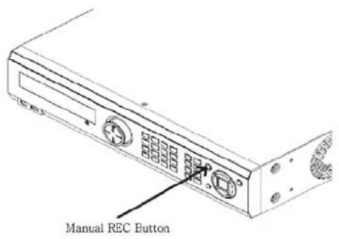
text_image
Manual REC ButtonSchedule Recording Settings
Schedule Recording records video automatically at a scheduled time according to the chosen program settings. Set the recording mode to Schedule & Event then select a program for a scheduled date and time.
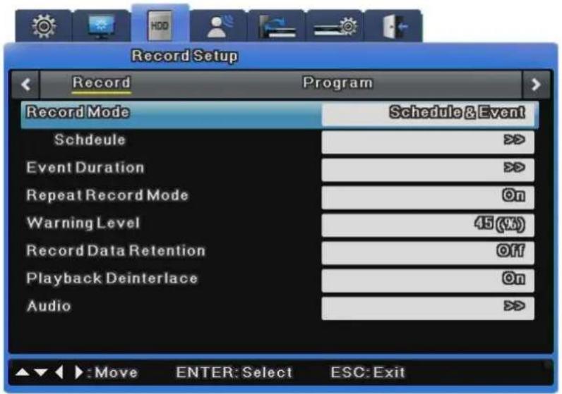
text_image
Record Setup Record Program Record Mode Schedule & Event Schedule > Event Duration > Repeat Record Mode On Warning Level 45 (%) Record Data Retention Off Playback Deinterlace On Audio > ▲▼ ▶: Move ENTER: Select ESC: ExitWhen selecting a program, the default settings value of the program is displayed for you to confirm. You can select one or more programs from among the 26 available, all labeled from A to Z. The picture below shows an example using only Program A.
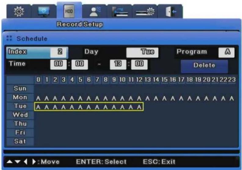
text_image
Record Setup Schedule Index 2 Day Tue Program A Time 00:00 13:00 Delete Sun Mon A A A A A A A A A A A A A A A A A Tue A A A A A A A A A A A A A A A A A A A Wed Thu Fri Sat ▲▼◀ :Move ENTER:Select ESC:Exit- Index: 1\~50 different programs can be set
• Day: designate recording date - Program: select a recording program (A\~T)
• Time: designate recording time
- Delete: delete the desired INDEX
Setting Method
As you set INDEX, DAY, PROGRAM and HOUR, then the content will be immediately displayed in the table. If you select the start time and the stop time for recording in the table and click on them in order, the content will be displayed in INDEX, DAY, PROGRAM and HOUR.
Deletion Method
Select the desired INDEX and then click on the Delete button. If you click on the Delete button before selecting INDEX, then the content of INDEX that was selected previously will be deleted first. After that, the content in the highest INDEX will be deleted and then others INDEX will be deleted in the increasing order of INDEX.
Editing Method
Select the INDEX to be edited and then change DAY, PROGRAM and HOUR on your own. If all the INDEX fields up to INDEX 50 are already set, then click on the time in the table to be edited with your mouse. Click on the hour in the table to be changed, again with your mouse. The previous setting will be deleted and overwritten with the change that you have just made.


me time is set twice then ‘!’ will be displayed in the table.
ou set the region of time, you may not include the existing time that
is set previously.
Record Setting
Repeat Record Mode
When there is no more space for recording to hard disk, recorded data is removed from the foremost portion automatically.
Warning Level
This checks the capacity of all disks connected to the DVR and gives a warning when the specified level is met.
Recorded Data Retention
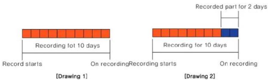
text_image
Recording lot 10 days Record starts On recording Recording starts On recording Recorded part for 2 days Recording for 10 days Recording for 2 days Drawing 1 Drawing 2This shows videos recorded only on specified dates in hard disk.
For example, if the entire video is recorded for 10 days (Drawing 1) and only 2-day recording (Drawing 2) is specified for playback, only the 2-day recording is available for playback.
Playback Deinterlace
This turns playback deinterlace on or off.
This is available only when the recording resolution is set to Full D1. If this is set to On, imaging shaking decreases while Full D1 video is paused.
6.5.3 Evnet Record Setup
This menu item is used to record video based on events. To use Event Recording, select a resolution, frame rate, and quality from the available 26 programs.
Event recording is divided into recording by sensor, by motion detection, by text and by digital input. In the Programs settings, select a program first. If you want to adjust the details of a program, select the program and then adjust the resolution, frame rate, and quality. (For more information, please refer to section 6.6.1 on Program Settings.)
Event Recording is used mostly in conjunction with other recording options: Manual & Event and Schedule & Event.
Go to [Record Setup] > [Record]. In "Record Mode," select Manual & Event or Schedule & Event.
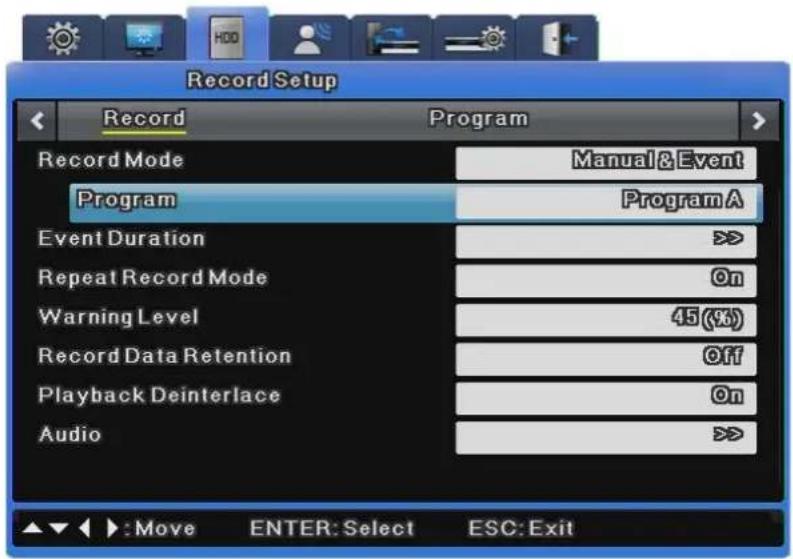
text_image
Record Setup Record Program Record Mode Manual&Event Program ProgramA Event Duration > Repeat Record Mode On Warning Level 45(%) Record Data Retention Off Playback Deinterlace On Audio >To use Event Recording only, please refer to the following instructions.

- In Record Mode, select Manual & Event or Schedule & Event.
- In the Program settings, change the frame rate of Normal Recording to 0 and of vent Recording to the desired rate.
- Set an Event Check to activate the recording.
Event Check Settings
This menu item sets times for event recording and has the options of Always, Disable and Timezone. The "Always" option always detects events while the "Timezone" option uses events only for specified hours. When Timezone is selected, a setup similar to schedule setup is possible; the event check time can be set by the hour.
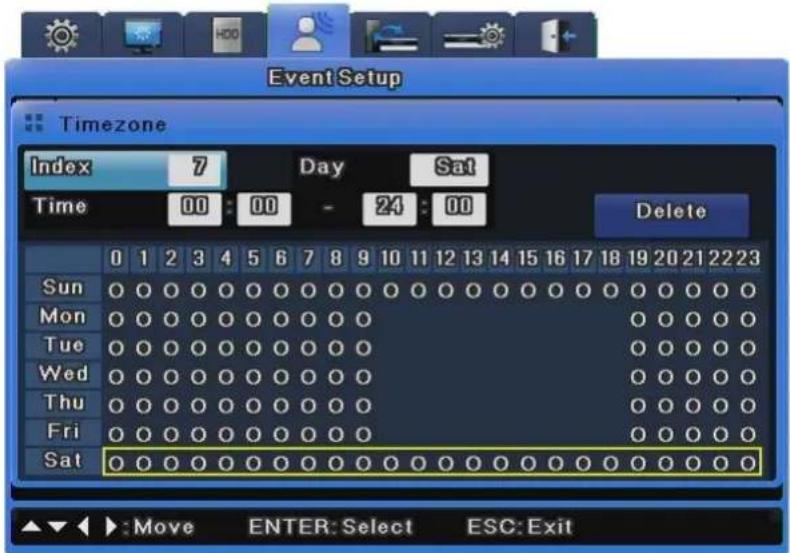
text_image
Event Setup Timezone Index 7 Day Sat Time 00:00 - 24:00 Delete Sun 0 1 2 3 4 5 6 7 8 9 10 11 12 13 14 15 16 17 18 19 20 21 22 23 Mon 0 0 0 0 0 0 0 0 0 0 0 0 0 0 0 0 0 0 0 0 0 0 0 0 Tue 0 0 0 0 0 0 0 0 0 0 0 0 0 0 0 0 0 0 0 0 Wed 0 0 0 0 0 0 0 0 0 0 0 0 0 0 0 0 0 Thu 0 0 0 0 0 0 0 0 0 0 0 0 0 0 Fri 0 0 0 0 0 0 0 0 0 0 0 0 0 Sat 0 0 0 0 0 0 0 0 0 0 0 0 0 0 0 0 0 0 0 ▲▼► :Move ENTER: Select ESC: Exit- INDEX : 1\~50 different programs can be set
• Day: designate recording date
• Time: designate recording time - Delete: delete the desired INDEX
Setting Method
As you set INDEX, DAY, and HOUR, then the content will be immediately displayed in the table. If you select the start time and the stop time for recording in the table and click on them in order, the content will be displayed in INDEX, DAY, and HOUR.
Deletion Method
Select the desired INDEX and then click on the Delete button. If you click on the Delete button before selecting INDEX, then the content of INDEX that was selected previously will be deleted first. After that, the content in the highest INDEX will be deleted and then others INDEX will be deleted in the increasing order of INDEX.
Editing Method
Select the INDEX to be edited and then change DAY, and HOUR on your own.
If all the INDEX fields up to INDEX 50 are already set, then click on the time in the table to be edited with your mouse. Click on the hour in the table to be changed, again with your mouse. The previous setting will be deleted and overwritten with the change that you have just made.
6.6 Audio Setup
This menu is used to set audio recording, sync or mixing.
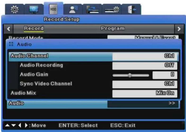
text_image
Record Setup Record Program Record Mode Manual&Event Audio Audio Channel Ctrl Audio Recording Off Audio Gain 0 Sync Video Channel Ctrl Audio Mix Mix On Audio >>6.6.1 Audio
This menu is used to set the audio channel, audio recording, audio gain and sync.
Audio Channel
Select a channel for audio.
Audio Recording
Decide whether to record audio. If No is selected, audio is outputted only for live video feeds. If Yes is selected, audio is outputted even for playback.
Audio Gain
This menu is used to adjust audio volume up or down.
Sync Video Channel
This menu is used to determine which channel the input audio is linked to for output. This is available only for recording. Audio output for live video feeds is described in Audio Mixing. If Sync Video Channel is set to 5 for Channel 1 audio, the audio inputted into Channel 1 is outputted when Channel 5 is selected. By default, Channel 1 audio is outputted to Channel 1 video.
6.6.2 Audio Mixing
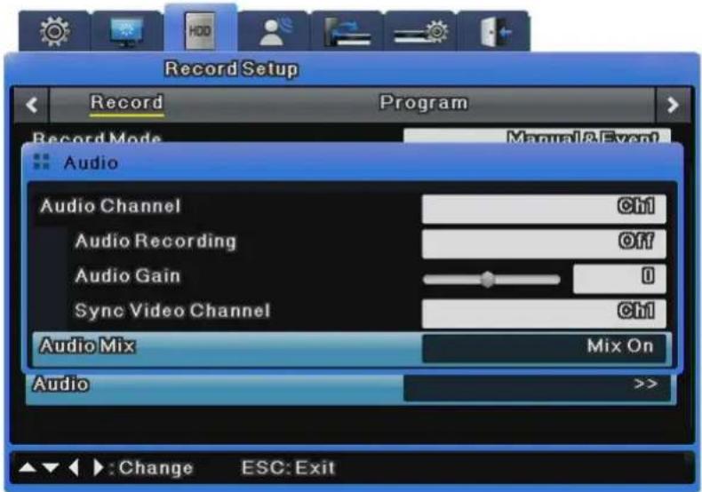
text_image
Record Setup Record Program Record Mode Manual&Event Audio Audio Channel Ctrl Audio Recording Off Audio Gain 0 Sync Video Channel Ctrl Audio Mix Mix On Audio >>: Change ESC: ExitThis menu is used to select audio for live video feeds. If All is set, all inputted audio is mixed for output regardless of channel selection. If specific audio is selected, only the specified channel is outputted regardless of the channel selection.
6.7 General Event Setup
This menu is used to set events that you want to use.
Motion Detection Setup
This menu is used to save events occurring through motion detection for each channel.
※ SVR-480 does not support Digital I/O
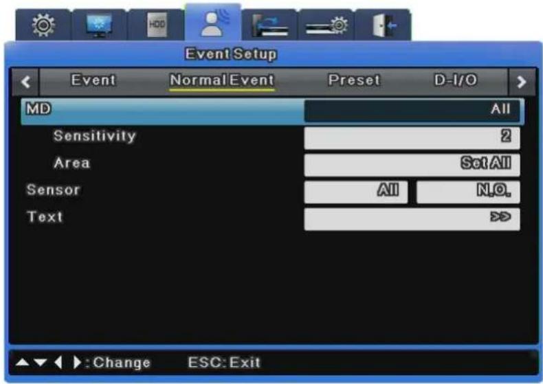
text_image
Event Setup Event Normal Event Preset D-I/O MD All Sensitivity 2 Area Set All Sensor All N.O. Text >>Motion Detection
This enables each channel or all channels to detect motion and notify users.
- Channel
Channel can be set to All or as follows.
SVR-3200: 1\~32CH
SVR-1680C/1660C/1645: 1\~16CH
SVR-960C/945: 1\~9CH
SVR-480:1\~4CH
- Sensitivity
Sensitivity can be set to Lowest, 1\~10, or Highest for each channel.
- Area
Area is used to set the motion detection area.
If Channel is set to All, Area can be set to Set All or Unset All. When each channel is set individually, Area can be set to Set All, Unset All or User Defined.
- User Defined
User Defined is only available when each channel is set individually. It is used to set an area where you want to detect motion intensely.
It allows you to set a user-defined motion detection area. You can select one or more motion detection areas out of the squares on the 22x15 grid.
The default setting is "Set All". Press the [Area Setup] button to open the motion detection area setup window.

natural_image
Street view through a grid overlay showing two rows of old European-style buildings with cars and vehicles (no visible text or signage)Users can specify motion detection areas on the screen.
The setup window composed of 330 squares in a 22x15 grid appears. Squares set as motion
detection areas turn gray. To select motion detection areas, use the navigation buttons to select them and press the [Enter] button or click them. Press the [ESC] button or right-click to return to the previous menu.
Sensor
A total of 16 sensors (9 sensors for the SVR-960C/945, 4 sensors for the SVR-480) can be set. If All is selected, all channels are set to N.O or N.C. You can select channels and set them individually to N.O., N.C. or Off.
6.7.1 Text Setup
Recording
You can turn recording for text input on or off.
Sync Text With
This selects channels to link with text data.
Seek Header
This parameter is not needed if, just like Star Finger-007, protocols are already registered and supported for various types of data that comes from external devices (Access Control, POS, ATM, etc.). However, this parameter is needed to see how one unit of data out of continuously incoming text data is structured. In other words, all data has its start and end points, and the header is data that is always inserted to indicate the start point. Therefore, by defining a header here, the DVR can recognize from the header that it is the start point of the data. Two headers can be set and detected because one device can send various types of data to external receivers.
Delimiter
The delimiter value may differ depending on the device used. For more information on delimiters, refer to the user manual or the device manufacturer.
Timeout (ms)
Lines defined below are the maximum number of text lines available for one piece of data. Even though data is standardized, lengths may differ. For example, three lines are programmed for client name input for an ATM, but if someone registers only his/her first name and last name, only two lines are provided when the person uses an ATM. However, the DVR cannot detect this automatically, so Timeout is used to determine how long is needed to recognize the received data as complete data after the last line is entered.
Lines
This defines the maximum number of lines for one piece of data.

An external device may not be recognized depending upon its characteristics, so it is recommended to contact the manufacturer before installation.
6.7.2 Preset
This menu is used to activate the presets specified in the PTZ based on sensor input.
Specify a preset with PTZ attached to each channel.
Select a channel in the preset menu and select an event for the preset.
You can choose sensor, MD or text for an event, and 16 presets can be set.
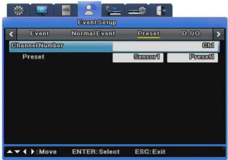
text_image
Event Setup Event Normal Event Preset D-I/O ChannelNumber Ch1 Preset Sensor1 Preset1 Move ENTER: Select ESC: Exit6.7.3 Digital I/O
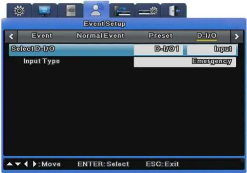
text_image
Event Setup Event Normal Event Preset D-I/O Select D-I/O D-I/01 Input Input Type Emergency Move ENTER: Select ESC: ExitDigital I/O are digital ports available for input and output at the same time., There are 12 digital inputs and outputs.
Digital I/O Channel & Input/Output
All 12 channels can be set to input/output. When channels are set to input, if an input signal is received by even one channel, emergency recording will operate. When they are set to output, if sensor input is received, it will operate.
In Digital I/O Setup, if you set one of the 12 Digital I/O to [Input], set Input Type to [Emergency] and turn Digital I/O on, the emergency recording will operate. The macro set in the event recording is used for the recording. The recording will continue based on the value set in [Recording After Event] under Event Recording and then stop.
※ SVR-480 does not support Digital I/O.
6.7.4 Event Action
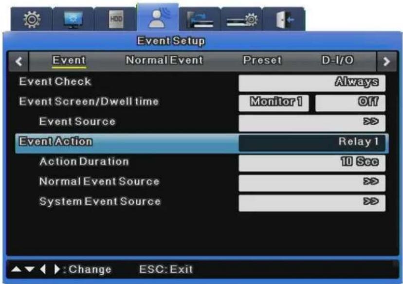
text_image
Event Setup Event Normal Event Preset D-1/0 Event Check Always Event Screen/Dwell time Monitor 1 Off Event Source >>> Event Action Relay 1 Action Duration 10 Sec Normal Event Source >>> System Event Source >>> ▲▼►: Change ESC: ExitThis sets actions based on event input.
Event Action
For Event Action, you can select Relay 1\~4, buzzer, or E-Mail.
Action Duration
Action Duration is used to maintain an action for a specified time when relay or buzzer is set. If E-Mail is set, e-mails are sent in specified time intervals. FTP transfers an image when a preset event occurs.
Normal Event Source
You can set Normal Event Source to 16 Sensors, 16 MDs, 16 Video Losses and Text, Emergency.
※ SVR-480 does not support Digital I/O, thus it does not display "Emergency" on select mode.
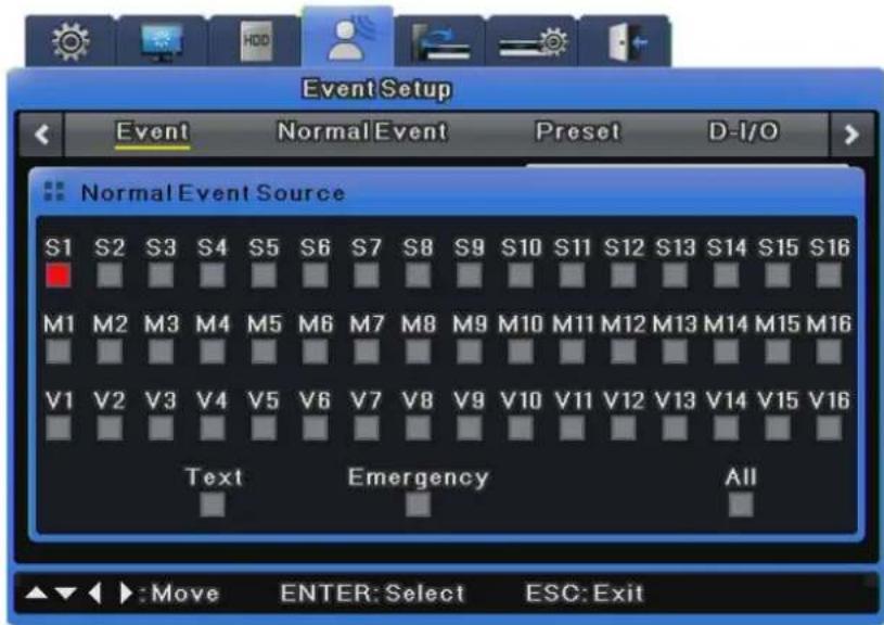
text_image
Event Setup Event NormalEvent Preset D-I/O Normal Event Source S1 S2 S3 S4 S5 S6 S7 S8 S9 S10 S11 S12 S13 S14 S15 S16 M1 M2 M3 M4 M5 M6 M7 M8 M9 M10 M11 M12 M13 M14 M15 M16 V1 V2 V3 V4 V5 V6 V7 V8 V9 V10 V11 V12 V13 V14 V15 V16 Text Emergency All :Move ENTER: Select ESC: ExitSystem Event Source
This sets some or all of disk error, disk full, fan error, authentication failure and DDNS registration failure.
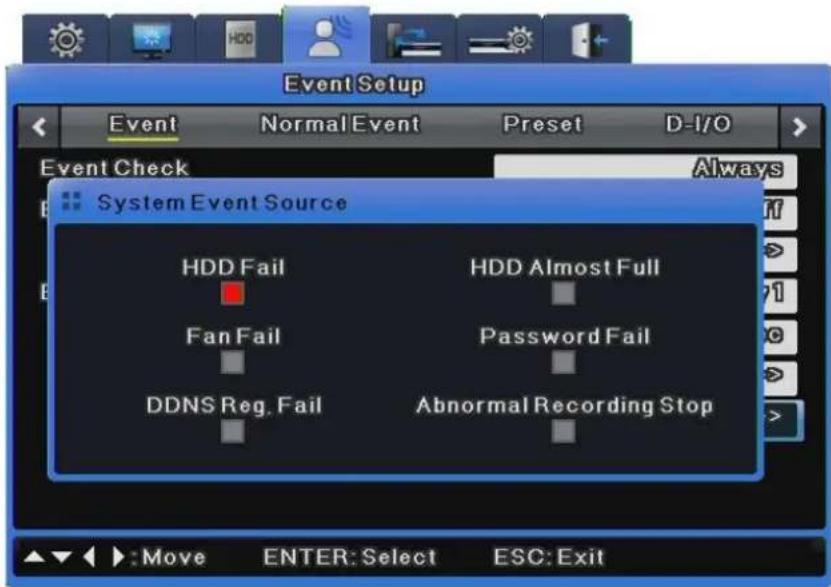
text_image
Event Setup Event Normal Event Preset D-I/O Event Check Always System Event Source HDD Fail HDD Almost Full Fan Fail Password Fail DDNS Reg. Fail Abnormal Recording Stop Move ENTER: Select ESC: ExitE-Mail Setup
E-Mail address is set when e-mail is used for output.
For e-mail address, enter an e-mail address for a message recipient.
The address format is xxxx@xxxxxx.xxx. However, only Roman alphabet letters and numbers are allowed.
- Sender Address
Sender Address is set when e-mail is used for output. The address format is xxxx@xxxxxx.xxx. You do not have to enter an e-mail address. In general, use an address that identifies the e-mail as being sent from a specific DVR.
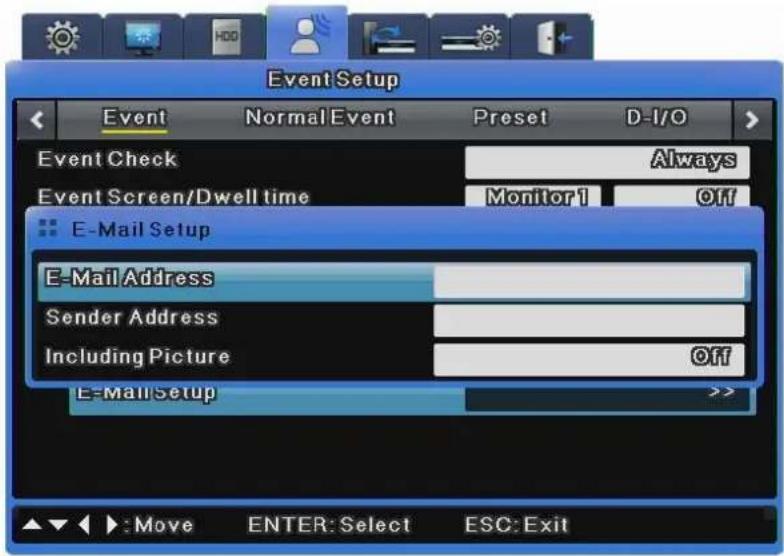
text_image
Event Setup Event Normal Event Preset D-I/O Event Check Always Event Screen/Dwell time Monitor 1 Off E-Mail Setup E-Mail Address Sender Address Including Picture Off E-Mail Setup >> ▲▼ : Move ENTER: Select ESC: Exit- Attaching Image Files
For a Normal event log, the system sends an e-mail attached with an image of the event channel along with the event information including the sensor, movement detection, and object disappearance.
For a System event log, the system sends only the event information because the channel pairing option is not available.
FTP Setup
Set to transfer a video to the FTP server when an event fires.
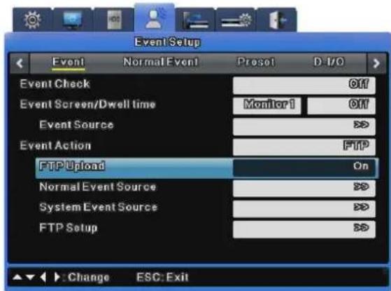
text_image
Event Setup Event Normal Event Preset D:\I/O Event Check Off Event Screen/Dwell time Monitor1 Off Event Source > Event Action FTP FTP Upload On Normal Event Source > System Event Source > FTP Setup > Change ESC: ExitFTP Upload
Send an image to the FTP server when an event fires.
Select 'On' to send an image to the FTP server.
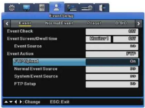
text_image
EventSetup Event Normal Event Preset D-1/O Event Check Off Event Screen/Dwell time Monitor 1 Off Event Source >>$ Event Action FTP FTP Upload On Normal Event Source >>$ System Event Source >>$ FTP Setup >>$ Change ESC: ExitServer URL
Enter the address of the FTP server.
User ID
Enter the login ID for the FTP server.
Password
Enter the password.
FTP Directory
Set the directory to transfer image files to on the FTP server.
Specify a directory in the FTP Directory setup to transfer files to; if this field is left blank, files are sent to the default folder.
Enter the name of the directory to save files to.
For example, if you enter "Download" in FTP Directory, create the "Download" folder in a sub-directory of the server.
Now, images are sent to the "Download" folder when events occur.
6.8 Network
This sets network information when connecting the DVR to a network.
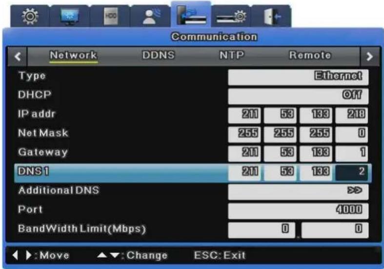
text_image
Communication Network DDNS NTP Remote Type Ethernet DHCP Off IP addr 210 53 133 218 Net Mask 255 255 255 0 Gateway 210 53 133 1 DNS1 211 53 133 2 Additional DNS >> Port 4000 BandWidth Limit(Mbps) 0 0 Move Change ESC: ExitType
This is used to select the network type (Ethernet/xDSL) connected to the DVR. Select Ethernet when the DVR is connected to dedicated line, cable modem or LAN.
Select xDSL when the DVR is connected to a PPPoE-type xDSL line. However, if the xDSL line is not of the PPPoE type, you must select Ethernet.
DHCP
Dynamic Host Configuration Protocol (DHCP) manages host addresses on a network. All the hosts on a LAN use this protocol to share limited IP addresses when accessing the Internet. In other words, a DHCP server allocates dynamic IP addresses to all the hosts on the LAN.
If the LAN has its DHCP server and the DHCP menu item is enabled, the DHCP server allocates an IP address to the DVR.
'DHCP' is used on a LAN with a DHCP server installed. Generally, small and large LANs have DHCP servers while small LANs use Network Address Translation (NAT) from a hub or router.
IP Addr
IP Address is used for communication between the DVR and Network Manager, and is also used when Webviewer accesses the DVR. This is available only when Net Mask and Gateway are set.
Net Mask
Net Mask specifies a range of IP addresses and enables IP addresses in the range to communicate. Net Mask should be allocated by a network administrator.
Gateway
Gateway must be specified to enable IP addresses to communicate and should be allocated by a network administrator.
DNS1
DNS1 must be specified to register the DVR to SWR while DNS Address should be allocated by a network administrator.
Additional DNS
Additional DNS is used to replace DNS1 when it is unstable or has a problem.
Port
Port is used to register to SWR, connect to Network Manager, or connect to Webviewer.

The default port is 4000. Be careful about the port entry when a PPPoE modem Internet sharing device are in use.
Bandwidth Limit (Mbps)
This sets the maximum transmission speed of data outputted from the DVR, or the data transmission capability of the DVR. This may be left blank. Ask your network administrator to specify it when necessary.
6.8.1 xDSL
If the DVR is connected to xDSL and uses PPPoE, set Type to xDSL and specify a user ID and password. You must use the user ID and password given when you subscribed to the xDSL service.
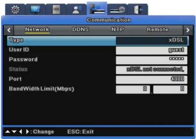
text_image
Communication Network DDNS NTP Remote Type xDSL User ID guest Password 0000 Status xDSL not connected. Port 4000 BandWidth Limit(Mbps) 0 0 Change ESC: ExitUser ID/Password
If the DVR is connected to xDSL, you must specify a user ID and password.
Status
This shows the connection status of the DVR.
6.8.2 DDNS
If the DVR is connected to a cable modem or an xDSL modem, a new IP address will be assigned each time the device connects to the ISP. In such a case, the user may not be able to find out the DVR's IP address. By registering a DVR with a dynamic IP address to a DDNS server, the DVR's IP may be identified by connecting to the DDNS server.
To register a dynamic IP address to a DDNS, follow the instructions shown below.
DDNS Registration procedure
1) Sign up at iPOLiS homepage.
- The homepage URL is [www.samsungipolis.com]
text_image
iPOLiS WHAT IS iPOLiS PRODUCT DENS SERVICE SUPPORT SAMSUNG NETWORK SECURITY SOLUTION NEW PRODUCT SNR-6400/3200 SNR-6400/3200 SNR-6400/3200 NETWORK VIDEO RECORDER Record up to 04/32 video/scale streams 1,280bps/N11, 152bps/P at full D1 MPEGAL/PED dual codes PAIDS, NAS, 4 expansion bin IQUICK SERVICE DENS REGISTRATION SAMSUNG CCTV SYSTEM The Browser in digital image security? DOWNLOAD CENTER REMOTE SERVICE iPOLiS Won iPOLiS products video dual images transmitted over the internet, next-time monitoring up-sensible atmosphere with an Internet connection. Easy sensitive content: wireless and the use of existing networks minimize instal- lation costs. GENERAL CATALOG SAMSUNG TECHN PROVACY / LEGAL NOTICE / CONTACT IS COPYRIGHT © SING 2009 NETWORK TECHN LLC SAMSUNG TECHN FAMILY SITE- Accept the terms and conditions, SIGN UP page: check ID availability
SIGN UP
HOME > Membership > SIGN UP
Welcome to the IPOLIS website.
We offer various services for users of Samsung iPOLIS network products. To use the services, please register first.
Manage your account
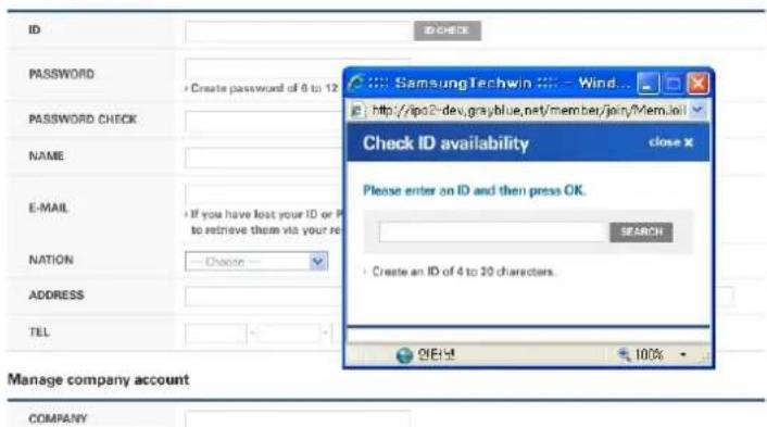
text_image
ID PASSWORD CREATE PASSWORD OF 6 TO 12 PASSWORD CHECK NAME E-MAIL If you have lost your ID or P to retrieve them via your re NATION Choose ADDRESS TEL Manage company account COMPANY SamsungTechwin Wind... http://ipo2dev.grayblue.net/member/join/Mem.io/ Check ID availability close X Please enter an ID and then press OK. SEARCH Create an ID of 4 to 30 characters. ONEXT 100%2) Register the product after sign up.
- Log on to iPOLiS website
LOGIN
HOME > Membership > Lgoin
WELCOME TO THE IPOLIS WEBSITE.
Please enter your ID and PASSWORD.


LOGIN
ID
PASSWORD
Not a member yet? Please register first.
Have you lost your ID or PASSWORD?

SIGN UP
FIND ID/PW
- Product List (If you didn't register products, there are no list)
MY DDNS
HOME > DDNS Service > MY DDNS
Current product list is displayed.
If wanted product is not in the list, click 'Product Registration' at the bottom.
| NO | DOMAIN | MODEL | LOCATION | STATUS | VIEW | MANAGEMENT | VIDEO TAG | ||
| 14 | demo1 | SVR-940 | Demo-Room | ON | Edit : Delete | - | |||
| 13 | jang400 | SNS-400 | Home | OFF | Edit : Delete | - | |||
| 12 | SNC570 | SNC-570 | asd | OFF | Edit : Delete | - | |||
| 11 | snc572 | SNC-570 | dfsa | ON | Edit : Delete | - | |||
| 10 | snd560 | SND-560 | aaa | ON | Edit : Delete | - | |||
| 9 | sns100 | SNS-100 | ON | Edit : Delete | OPEN | LOGIN | VIDEO INSERTING | ||
| 8 | sns400 | SNS-400 | SungNam | OFF | Edit : Delete | OPEN | LOGIN | VIDEO INSERTING | |
| 7 | svr1640 | SVR-1640 | SungName Lab | OFF | Edit : Delete | - | |||
| 6 | svr1680kim | SVR-1680 | OFF | Edit : Delete | - | ||||
| 5 | svr450 | SVR-450 | Starbucks | OFF | Edit : Delete | - | |||
| 4 | svr450cs1 | SVR-450 | ON | Edit : Delete | - | ||||
| 3 | svr450cs2 | SVR-450 | ON | Edit : Delete | - | ||||
| 2 | svr940 | SVR-940 | OFF | Edit : Delete | - | ||||
| 1 | svr950 | SVR-950 | Lab | ON | Edit : Delete | - | |||
< 1 >
PRODUCT REGISTRATION >
- Product Registration (Check ID availability), Information regarding the registered products may be reviewed from the list
MY DDNS
H HOME > DDNS Service > MY DDNS
Register a new IPOLIS product and manage your videos in real time.
• Mandatory Information
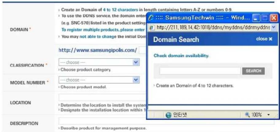
text_image
DOMAIN * Create an Domain of 4 to 12 characters in length containing letters A-Z or numbers 0-9. To use the DDNS service, the domain enter (e.g. SNC-570) listed in the product setting To register multiple products, please enter You may not able to change the initial Dom Domain Search close http://www.samsungipolis.com/ CLASSIFICATION * choose -- Choose product category. MODEL NUMBER * choose -- Choose product model. LOCATION Determine the location to install the system Designate the installation location within 1 DESCRIPTION Describe product for management purpose. Check domain availability. SEARCH Create an Domain of 4 to 12 characters. 인터넷 100%REGISTRATION > CANCEL >
3) Configure the product for DDNS
From the DVR's Network Setup menu, configure the settings as shown below. Select Menu and Network to prompt a screen similar to the illustration shown below. Set DDNS to "On" and input the DDNS address in 'DDNS SERVER DOMAIN NAME'. (The default value is www.samsungipolis.com.) For ID and PW, use the user ID (domain) and password used in iPOLiS product registration process.
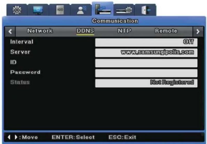
text_image
Communication Network DDNS NTP Remote Interval Off Server www.samsungipolis.com ID Password Status Not Registered +:Move ENTER:Select ESC:ExitThis concludes the necessary configurations to the DVR for DDNS connection.
4) The connection status of product can be checked on the product list.
- The Product list will display status 'On' for the connected device
MY DDNS
HONE > DONS Service > NY DONS
Current product list is displayed.
If wanted product is not in the list, click 'Product Registration' at the bottom.
| NO | DOMAIN | MODEL | LOCATION | STATUS | VIEW | MANAGEMENT | VIDEO TAG | ||
| 14 | demo1 | SVR-940 | Demo-Room | ON | Edit Delete | - | |||
| 13 | Jang800 | SNS-900 | Home | OFF | Edit Delete | - | |||
| 12 | SNC570 | SNC-570 | asd | OFF | Edit Delete | - | |||
| 11 | snc572 | SNC-570 | dfta | ON | Edit Delete | - | |||
| 10 | snd580 | SND-580 | aaa | ON | Edit Delete | - | |||
| 9 | svr100 | SNS-100 | ON | Edit Delete | OPEN | LOGIN | VIDEO INSERTING | ||
| 8 | sns400 | SNS-400 | SungNom | OFF | Edit Delete | OPEN | LOGIN | VIDEO INSERTING | |
| 7 | svr1640 | SVR-1640 | SungNom Lab | OFF | Edit Delete | - | |||
| 6 | svr1680 in | SVR-1680 | OFF | Edit Delete | - | ||||
| 5 | svr450 | SVR-450 | Starbucks | OFF | Edit Delete | - | |||
| 4 | svr450cs1 | SVR-450 | ON | Edit Delete | - | ||||
| 3 | svr450cs2 | SVR-450 | ON | Edit Delete | - | ||||
| 2 | svr540 | SVR-940 | OFF | Edit Delete | - | ||||
| 1 | svr550 | SVR-950 | Lab | ON | Edit Delete | - | |||
[VIEW]: See the log-in page of selected product
[Edit]/ [Delete]: Edit/Delete the selected product
Once the product has been registered, its ID (domain) may not be changed. When the product's ID needs to be changed, the product's registration must be reset. Register the product again with the new ID.
To register a fixed IP address to a DDNS, follow the instructions shown below.
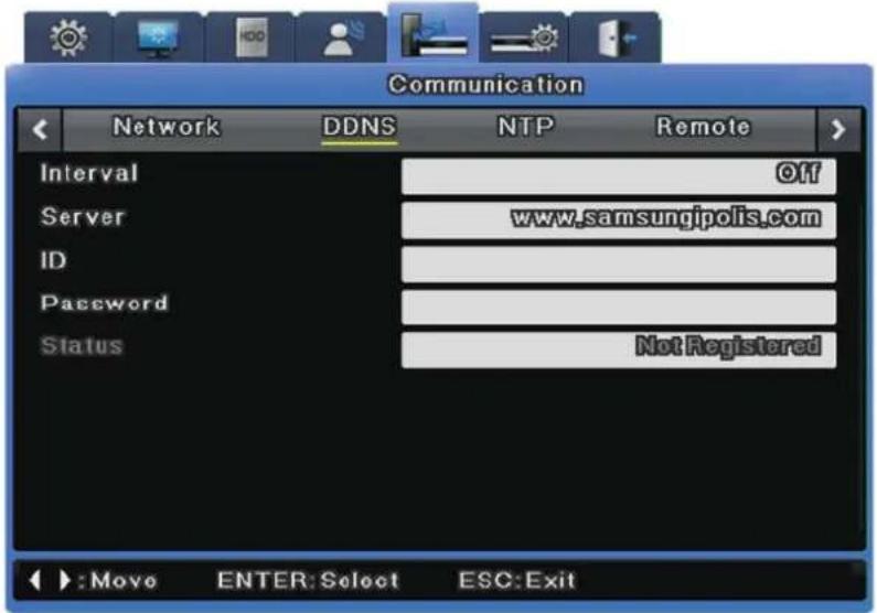
text_image
Communication Network DDNS NTP Remote Interval Off Server www.samsungipolis.com ID Password Status Not Registered Move ENTER: Select ESC: ExitInterval
To maintain continuous registration status, a registration cycle must be assigned from "Interval".
A dynamic IP address will renew the relevant data from the DDNS per each interval. If the user sets the registration interval to "Disabled" or the DVR does not upload any information over two days, information regarding the DVR will be removed from the DDNS database.
Server
This menu is used to configure the server address to be registered. The address of the SWR is www.samsungipolis.com.
ID
Use the ID for the DDNS login.
Password
Use the password for the DDNS login.
Status
The DVR's registration status is indicated. "Not Registered" means that the DVR is not registered to the DDNS. "Date/Time & OK" means that the DVR has been registered to the DDNS.
6.8.3 NTP
Network Time Protocol (NTP) synchronizes time between devices on network. On a network, there is a server that provides the base time and clients that receive the time from the server for synchronization.
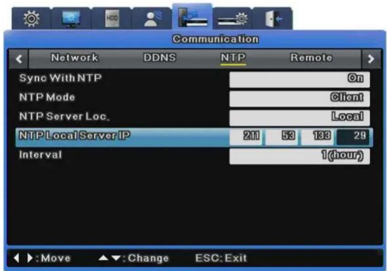
text_image
Communication Network DDNS NTP Remote Sync With NTP @n NTP Mode Client NTP Server Loc. Local NTP Local Server IP 211 53 133 29 Interval 1(hour) Move Change ESC: ExitSync With NTP
This turns NTP on or off.
NTP Mode
This sets NTP Mode to Client, Server or All.
NTP Server Location
This is enabled when NTP Mode is set to Client. This determines whether the NTP server is on a local network or on the Internet.
NTP Local Server IP
This is enabled when the NTP Server Location is set to Local and is used to set the IP of the NTP server. Enter either the IP of an NTP server on the local network or the IP of a DVR with its NTP mode set to Server.
Interval
This menu is used to set the synchronization interval.

When NTP Mode is set to Client, Sync With NTP must be set to On.
6.8.4 Remote
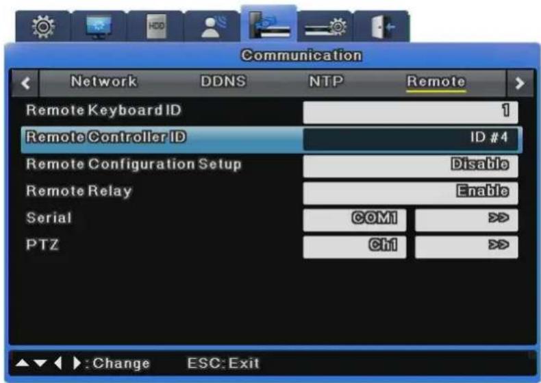
text_image
Communication Network DDNS NTP Remote Remote Keyboard ID 1 Remote Controller ID ID #4 Remote Configuration Setup Disable Remote Relay Enable Serial COM1 >> PTZ Ch1 >> Change ESC: ExitDVR ID
This sets the address of the keyboard when operating all DVR functions with the controller buttons. The default value is "1". If one keyboard is connected to several DVRs, it might conflict with other channels, so a different value should be set for the keyboard address.
Remote Controller ID
Up to 16 remote controller IDs can be set. You can use one remote controller to operate up to 16 DVRs.
How to register the remote controller is as shown below.
- Direct the remote controller to the DVR.
- Press the [ID] button based on the specified remote controller ID.
- If the remote controller ID and the DVR ID are the same, the DVR buzzer beeps.
- The remote controller is now configured and available for use.
Remote Configuration Setup
This determines whether to use the SNM Configuration program for setup.
If "Enable" is set, SNM Configuration is available for setup. If "Disable" is set, SNM Configuration is unavailable for setup.
Remote Relay
Remote Relay is used to determine whether to use the Relay On/Off function on the SNM monitor.
If "Enable" is set, all four relays can be controlled remotely. If "Disable" is set, remote control is unavailable with the SNM Configuration.
6.8.4.1 Serial Port
A total of four serial ports are available for the DVR. Two are RS-232C(Com1, Com3) and the other two are RS-422/485(Com2, Com4).
The Serial Port settings are available under Communication > Remote.
The following options are provided for the Serial Port settings.
※ A total of 3 serial ports are available for SVR-480. One is RS-232C(Com1), and the other two are RS-485(Com2,3).
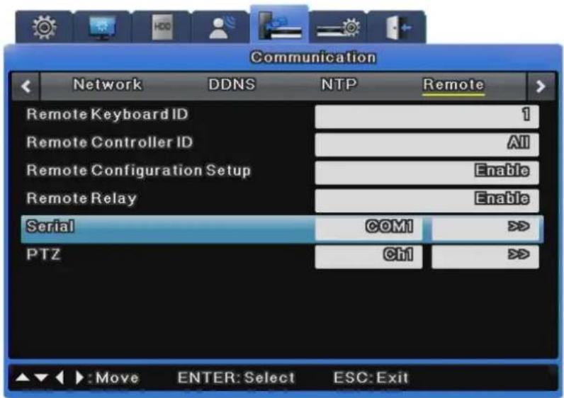
text_image
Communication Network DDNS NTP Remote Remote Keyboard ID 1 Remote Controller ID All Remote Configuration Setup Enable Remote Relay Enable Serial COM1 >> PTZ Ch1 >> ▲▼ :Move ENTER: Select ESC:Exit6.8.4.1.1 Text
To use the Text option, please follow the instructions below.
Please note that the Text option supports only Com1 (RS-232); make sure to select Com1 on the Serial Port menu.
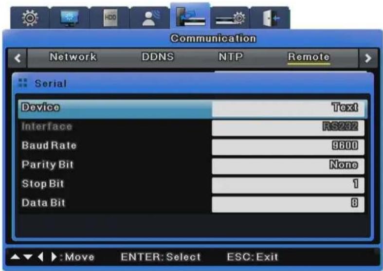
text_image
Communication Network DDNS NTP Remote Serial Device Text Interface RS282 Baud Rate 9600 Parity Bit None Stop Bit 1 Data Bit 8 ▲▼ :Move ENTER: Select ESC: ExitDevice
Select Text.
Interface
Select RS-232.
Baud rate/Parity/Stop Bit/Data Bit
Enter the same settings as the ones for the selected TP device.
6.8.4.1.2 Transparent
To use a transparent device, please follow the instructions below.
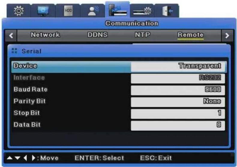
text_image
Communication Network DDNS NTP Remote Serial Device Transparent Interface RS232 Baud Rate 9600 Parity Bit None Stop Bit 1 Data Bit 8 ▲▼ :Move ENTER: Select ESC: ExitDevice
Select a connected transparent device.
Interface
Select COM1 or COM3.
※ Only Com1 is available for SVR-480.
Baud rate/Parity/Stop Bit/Data Bit
Enter the same settings as the ones for the selected Transparent device.
6.8.4.1.3 Keyboard
To set up a keyboard, select Keyboard for the Device option, and then select a keyboard model.
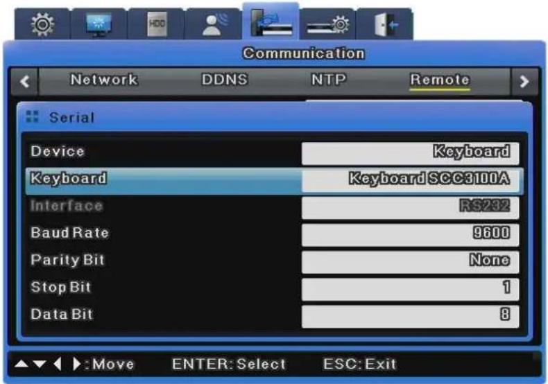
text_image
Communication Network DDNS NTP Remote Serial Device Keyboard Keyboard Keyboard SCC3100A Interface RS232 Baud Rate 9600 Parity Bit None Stop Bit 1 Data Bit 8 ▲▼ :Move ENTER: Select ESC: ExitDevice
Select Keyboard.
Keyboard
Select a desired keyboard model.
Interface
Select COM1 or COM3.
※ Only Com1 is available for SVR-480.
Baud rate/Parity/Stop Bit/Data Bit
Enter the same settings as the ones for the selected keyboard.
6.8.4.1.4 PTZ
Select PTZ.
To control the PTZ operation via serial port, select PTZ in the Device options, and then set up a serial port; refer to 6.8.4.2.2 PTZ (Serial).
To control the PTZ operation via coax protocol, you do not need to set up this option. (Refer to 6.8.4.2 PTZ.)
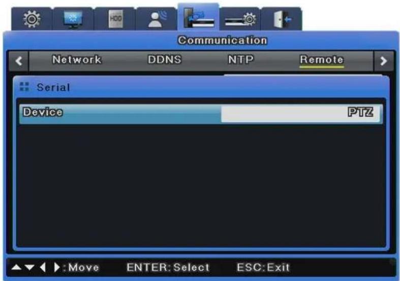
text_image
Communication Network DDNS NTP Remote Serial Device PTZ Move ENTER: Select ESC: ExitDevice
Select a connected PTZ device.
6.8.4.2 PTZ
Two PTZ control methods are available: via serial port and coax protocol.
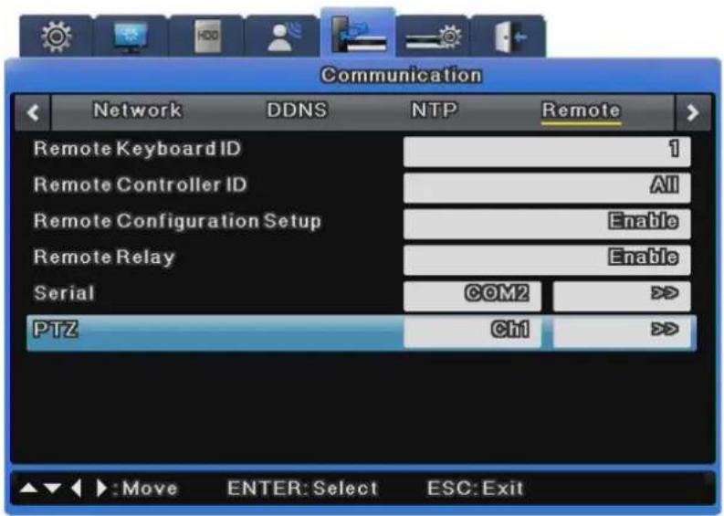
text_image
Communication Network DDNS NTP Remote Remote Keyboard ID 1 Remote Controller ID All Remote Configuration Setup Enable Remote Relay Enable Serial COM2 >> PTZ Ch1 >> :Move ENTER:Select ESC:Exit6.8.4.2.1 PTZ(Coax)
The Coax Protocol option does not support normal PTZ protocols, but rather supports the Pelco Standard and Extended Protocols.
The standard protocol supports basic PTZ functions such as PTZ and presets. The extended protocol supports more expansive features such as menu control and video playback in addition to the basic PTZ functions.
To use this option, a PTZ device must be embedded with a coax standard or extended protocol.
※ SVR-3200, SVR-1645, SVR-945, SVR-480 does not support coaxial function.
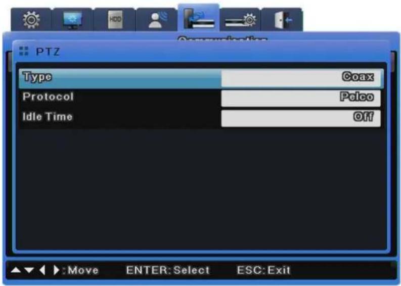
text_image
PTZ Type Coax Protocol Pelco Idle Time Off Move ENTER: Select ESC: ExitType
Select Coax.
Protocol
Select Pelco or Pelco Extended according to the coax protocol type of Pelco camera.

AD Dome does not support menu control, Presets or AUX when setup with a coax protocol.
Idle Time
Activate or disable PTZ Home, and setup a standby duration of the device before moving to PTZ home.
6.8.4.2.2 PTZ(Serial)
Select PTZ.
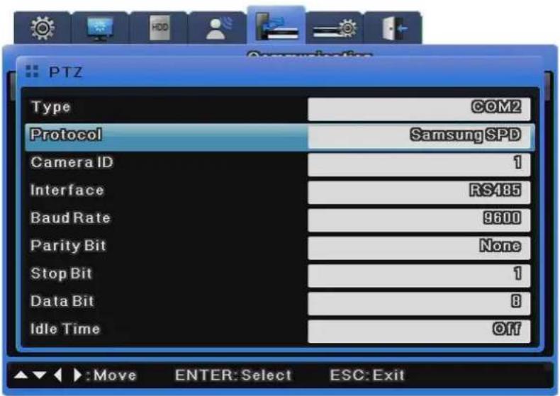
text_image
PTZ Type COM2 Protocol SamsungSPD Camera ID 1 Interface RS485 Baud Rate 9600 Parity Bit None Stop Bit 1 Data Bit 8 Idle Time Off ▲▼ :Move ENTER:Select ESC:ExitType
Select a serial port.
Protocol
Select a connected PTZ device.
Camera ID
Enter the ID of the selected camera.
Interface
Select one from among Com2 to 4.
To use RS-232, select Com3. For RS-422 or 485, select Com2 or 4.
Baud rate/Parity/Stop Bit/Data Bit
Enter the same settings as the ones for the PTZ device.
Idle Time
Activate or disable PTZ Home, and set up a standby duration for the device before moving to PTZ home.

For more information on cameras supporting PTZ and how to set them up, refer to "4.8 PTZ Use".
6.9 System Setup
6.9.1 System Setup
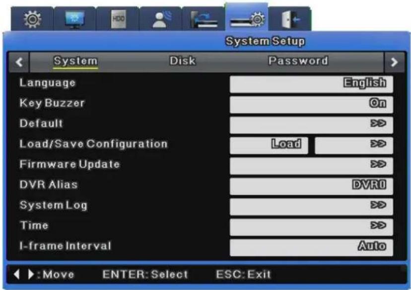
text_image
System Setup System Disk Password Language English Key Buzzer On Default >> Load/Save Configuration Load >> Firmware Update >> DVR Alias DVR0 System Log >> Time >> I-frame Interval Auto : Move ENTER: Select ESC: ExitLanguage
The OSD menu supports multiple languages. Select a language.
Key Buzzer
This determines whether to use the buzzer for the buttons on the front.
Default
This restores the factory default settings. Press the [Default] button to restore the factory default.
Load Configuration
This sends the DVR setting stored in a USB storage device to the DVR.
Save Configuration
This saves the DVR setting to a USB storage device.
Firmware Update
Save the Update Firmware for USB to USB storage and connect it to the DVR.
Select Firmware Update from System Setup and press the [Enter] button.
When a message prompting you to update appears, select [Yes] and press the [Enter] button.
After a while, a buzzer beeps and the unit reboots.
The Update Firmware for USB is provided in a "*.dat" file.
To do a firmware update through the network, run the updater executable file and click a DVR on the DVR list. When the IP, MAC address and port of the DVR are displayed, enter the password (default: 11111111) specified in SNM-128S into "Admin Password" and press the [Start Upgrade] button.
After the upgrade progress window appears, a message prompting you to reboot the unit is displayed. Select "Yes" to reboot the unit.
DVR Alias
This sets a DVR alias.
System Log
The system logs various events including changing menu settings, turning the power on or off, changing the time zone, turning HDD on or off, using the Copy function, and when system events occur.
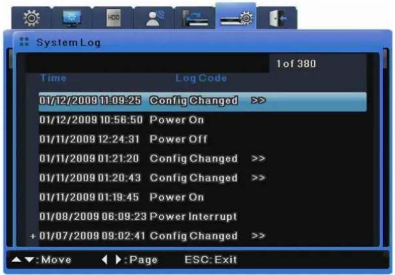
text_image
System Log 1 of 380 Time Log Code 01/12/2009 11:09:25 Config Changed >> 01/12/2009 10:56:50 Power On 01/11/2009 12:24:31 Power Off 01/11/2009 01:21:20 Config Changed >> 01/11/2009 01:20:43 Config Changed >> 01/11/2009 01:19:45 Power On 01/08/2009 06:09:23 Power Interrupt + 01/07/2009 09:02:41 Config Changed >>You can check log details with the >> icon by pressing the Enter button or scrolling the mouse wheel.
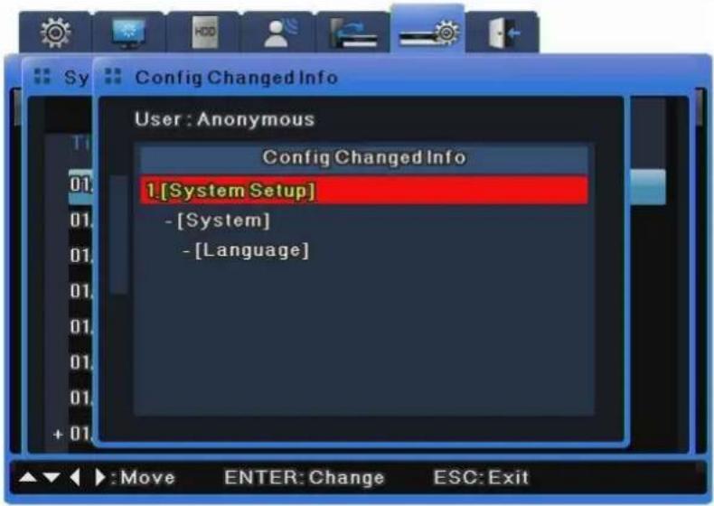
text_image
Config Changed Info User : Anonymous Config Changed Info 1.[System Setup] - [System] - [Language]Copying System Log
System logs are saved as txt-formatted files, and can be saved to a USB flash drive.
To save system logs to a USB drive, insert the drive into a USB port, open the System Log list.
And then press the "COPY" button on the front.
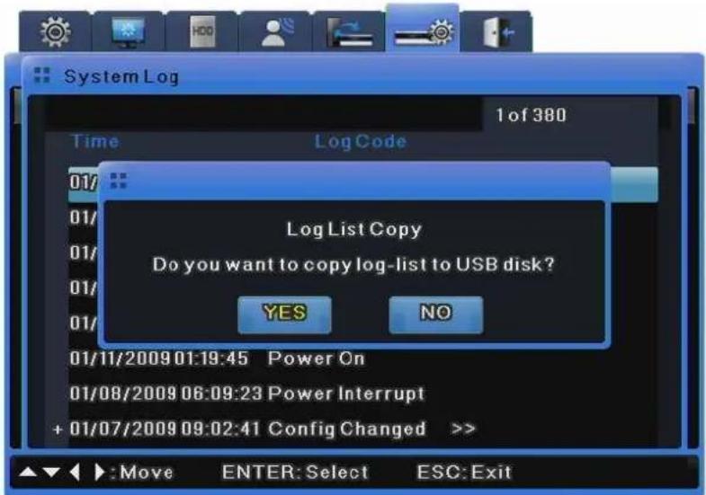
text_image
System Log 1 of 380 Time Log Code 01/ 01/ 01/ 01/ 01/ 01/ 01/ 01/11/2009 01:19:45 Power On 01/08/2009 06:09:23 Power Interrupt + 01/07/2009 09:02:41 Config Changed >> Log List Copy Do you want to copy log-list to USB disk? YES NO Move ENTER: Select ESC: ExitThe data will be saved as "Model Name_System Log_Date&Time.txt."
Time
This is used to set the time zone, date format, and time for the DVR.
Daylight Saving needs to be set depending upon the region.
I-Frame Duration
An I-frame duration is the interval between I-frames and is measured by the video frame rate.
For video recordings with less motion, I-frame duration enhances the video quality.
You should only set I-frame duration settings to anything other than Auto if you are specialized in MPEG-4.
6.9.2 Disk
This section describes how to add, remove, or format internal and external hard disks.
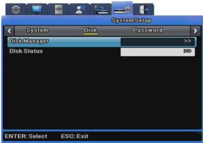
text_image
System Setup System Disk Password Disk Manager >> Disk Status DD ENTER: Select ESC: ExitDisk Manager
Disk Manager is used to manage internal and external HDDs.
It manages HDD status, bad blocks, size, enabled, disabled, etc.
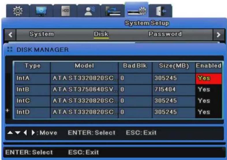
text_image
System Setup System Disk Password DISK MANAGER Type Model Bad Blk Size(MB) Enabled IntA ATA ST3320820SC.. 0 305245 Yes IntB ATA ST3750640SV.. 0 715404 Yes IntC ATA ST3320820SC.. 0 305245 Yes IntD ATA ST3320820SC.. 0 305245 Yes ▲▼◀ ▶:Move ENTER: Select ESC: Exit ENTER: Select ESC: ExitType : Displays disk locations and types. Int A (Internal A HDD), Int B (Internal B HDD), Ext (External HDD)
Model : Displays HDD models.
Bad Block : Displays HDDs with bad blocks. 0 is displayed when there are no problems. Nothing is displayed for HDDs not in use.
Size(MB) : Displays HDD sizes in MB.
Enabled : Enables or disables HDDs.
Yes: Enabled / No: Disabled
To change HDD to Yes
- Enabled: Select No and press the [Enter] button or use the mouse wheel to open the notice window with the following message.
- "Warning: This disk is usable without being formatted. Do you want to format the disk anyway?"
- Select No to keep the previous data stored in the HDD and change it to Enabled-Yes.
- Select Yes to delete the previous data stored in the HDD and change it to Enabled-Yes.
To change HDD to No
- Enabled: Select Yes and press the [Enter] button or use the mouse wheel to open the notice window with the following message.
- "Warning: Do you want to remove the disk?"
- Select Yes to open the "The disk has been removed." message and change the HDD to Enabled-No.
- The HDD is now unused.
- Select No to keep the HDD as it is.
Disk Status
This displays the temperature and status for each HDD.
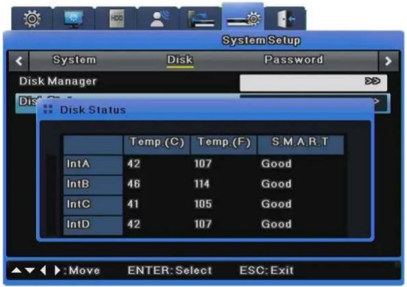
text_image
System Setup System Disk Password Disk Manager Disk Status Temp.(C) Temp.(F) S.M.A.R.T IntA 42 107 Good IntB 46 114 Good IntC 41 105 Good IntD 42 107 Good Move ENTER:Select ESC:Exit6.9.3 Security
DVR users are divided into administrators and general users. Administrators can use all DVR features without any limitations. The maximum number of users is 10. They can only use features that they have permissions for.
Right
In Right Setup, if Check is set to all X, all users can use all features without any limitations.
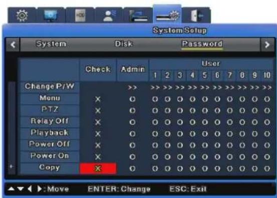
If Check is set to all O, each user can use only features for which they have been given permissions.
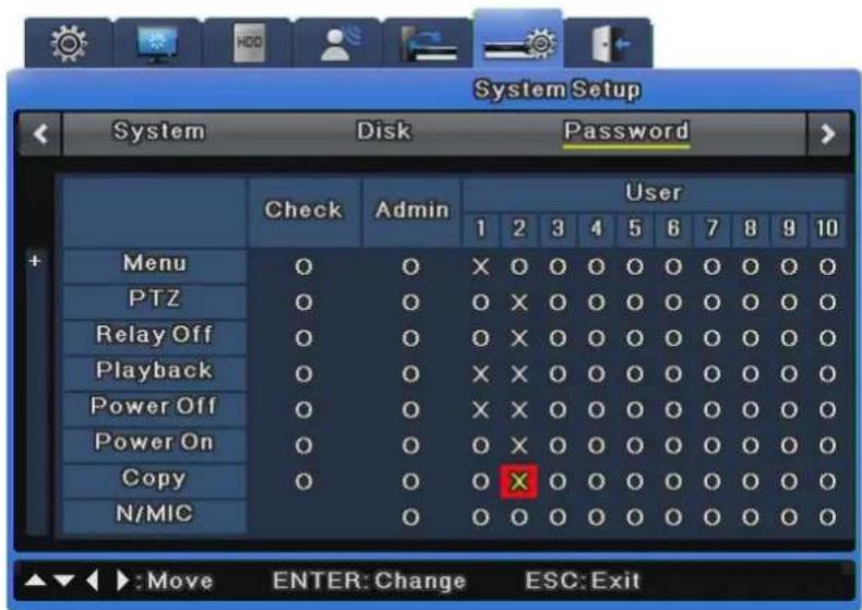
In the image above, User 1 & 2 can use only "O" function. You can set User 1 to User 10 in the same way.
Admin Password
The default Admin Password is "11111111" and can be changed. The Admin Password should be an 8-digit number.
User Password
User 1's password is "11111111", User 2's is "22222222", and similarly for User 3 to User 9. User 10's password is "00000000". The 16 channel-DVRs do not have a [0] (zero) button so they use the [10] (ten) button instead.
Change Password
As shown in the image below, click Change P/W for a user you want to change.
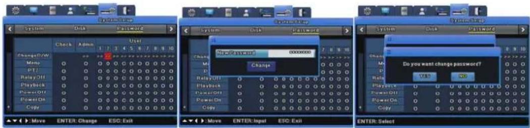
The password input window appears. Use the number buttons on the front or the character input window to enter a new password. Click the [Change] button to save it.
Clicking the [Change] button displays a popup confirmation window that prompts you to change password. Click Yes.
The password has been changed.
Permissions
Using permission restricted features requires a password check. Execute a command to open the password input window. Select a user and enter his/her password. Now the function is available.

text_image
PTZ CHECK User User1 Password[Permission check]
6.10 Exit
This exits with or without saving menu settings.
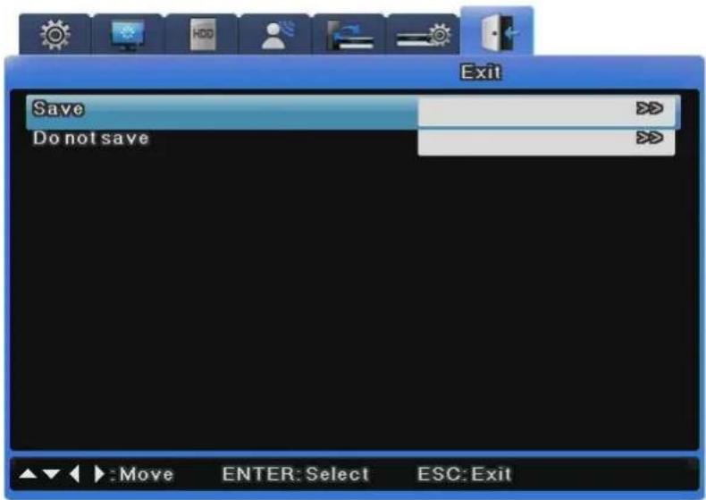
text_image
Exit Save Do not save Move ENTER: Select ESC: ExitSave
This saves all settings and exits to the live screen.
Select Yes to save all settings and exit, or select No to exit without saving any settings.
Do not save
This is used to exit without saving any settings.
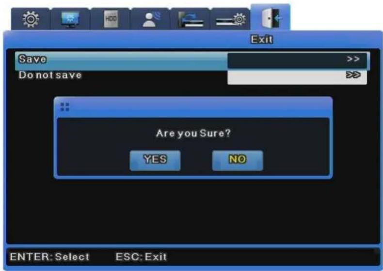
text_image
Exit Save Do not save Are you Sure? YES NO ENTER: Select ESC: ExitChapter 7. Web Viewer
Web Viewer is a web application provided as a complement for the DVR, capable of receiving visual live feeds and playing recorded data from a distance over the Internet. Web Viewer's structure consists of the log-in page, monitoring monitor and playback monitor. Detailed descriptions of the components are as follow.
7.1 System Requirements
| Minimum | Recommended | |
| CPU Intel Pentium 4 / 3.0GHz Core2duo E6750 or higher | ||
| Main Memory 1GB | 2GB or higher | |
| Video Memory 128MB | 512MB or higher | |
| Display Resolution 1280 x 1024 (with 32bit color) or higher | ||
| HDD 1GB or higher | ||
| OS Windows | XP Professional / Window Vista Business | |
| Others DirectX | 9.0 or higher | |
7.2 LOGIN

text_image
iPOLiS Network Products Administration USER ID PASSWORD Login Samsung Techwin The pages look well with the explore $5 above was Canara Solution by Samsung Techwin Co., Ltd. Copyright© 2007 SAMSUNG TECHWIN CO.,LTD. www.sAMSUNGtech.comUse the IP address and port assigned to the product to access the Web Viewer Log-in page. The URL to access the page will be similar to http://192.168.1.100:4000. If the port value has been changed from the default value of 4000, use the changed value instead after the colons. Use the ID and password from SNM-128S and click "Login". The default ID and password are [admin] and [11111111] (eight ones). The password may be changed, but the ID may not.

To change the DVR's administrator password or issue new user ID and password, refer to "7.3 Connection User Setup".
7.3 Connection User setup
To log into Web Viewer, the user ID and password must be entered to Network Manager's Configuration Tool.
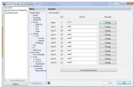
text_image
Network Manager 3.0 Configuration Form My Units and Web Start of SAMSUNG Local Area Units Menu Account User Account Use User ID Placement Address user1 user2 user3 user4 user5 user6 user7 user8 user9 user10 User Account User Account User Account User Account User Account User Account User Account User Account User Account User Account User Account User Account User Account User Account User Account User Account User Account User Account User Account User Account User Account User Account User Account User Account User Account User Account User Account User Account User Account User Account User Account User Account User Account User Account User Account User Account User Account User Account User Account User Account User Account User Account User Account User Account User Account User Account User Account User Account User Account User Account User Account User Account User Account User Account User Account Users Add Remove Edit Edit Add Edit Add Edit Add Edit Add Edit Add Edit Add Edit Add Edit Add Edit Add Edit Add Edit Add Edit Add Edit Add Edit Add Edit Add Edit Add Edit Add Edit Add Edit Add Edit Add Edit Add Edit Add Edit Add Edit Add Edit Add Edit Add Edit Add Edit Add Edit Add Edit Add Edit Add Edit Add Edit Add Edit AddUp to 1 administrator and 10 regular user IDs and passwords may be issued. For security purposes, the administrator and regular passwords must be distinct. Uncheck the usage box of
unused user accounts as well.
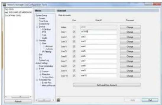
text_image
Network Manager Job Configuration Tools My Units Job Relationship OF SAMSUNG Local Area Units Meme User Accounts System Setup Screen Time-Date Connectivity Device CDM Plus PTZ Test Audio Security User Account Authority IP Financing Disk Etc System Log Author Setting Tree Scheduling Area Source Position System Bus Schedule Plan Event Plan Manual Process Admin Use 1 Use 2 Use 3 Use 4 Use 5 Use 6 Use 7 Use 8 Use 9 Use 10 Use 11 Use 12 Use 13 Use 14 Use 15 Use 16 Use 17 Use 18 Use 19 Use 20 Use 21 Use 22 Use 23 Use 24 Use 25 Use 26 Use 27 Use 28 Use 29 Use 30 Use 31 Use 32 Use 33 Use 34 Use 35 Use 36 Use 37 Use 38 Use 39 Use 40 Use 41 Use 42 Use 43 Use 44 Use 45 Use 46 Use 47 Use 48 Use 49 Use 50 Use 51 Use 52 Use 53 Use 54 Use 55 Use 56 Use 57 Use 58 Use 59 Use 60 Use 61 Use 62 Use 63 Use 64 Use 65 Use 66 Use 67 Use 68 Use 69 Use 70 Use 71 Use 72 Use 73 Use 74 Use 75 Use 76 Use 77 Use 78 Use 79 Use 80 Set Local Use AccountThe illustration above displays Network Manager Configuration Tool after user IDs and passwords have been changed.
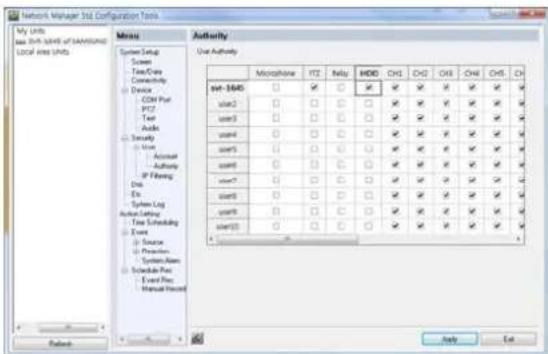
text_image
Network Manager Unit Configuration Tools My Units Use Shift Units of SAMSUNG Local Units Units Menu System Setup Screen Time/Case Connecting Device COM Part IP27 Text Audio Specialty User Account Authority IP Freeing Disk Ex System Log Action Setting Time Scheduling Event Source Preferent System Name Schedule Pres Event Pres Manual Protocol Authority Use Authority Monolithic IT2 Relay MDD CHS CHS CHS CHS CH set-1645 □ ✓ □ ✓ ✓ ✓ ✓ ✓ ✓ ✓ user2 □ □ □ □ ✓ ✓ ✓ ✓ ✓ ✓ ✓ ✓ ✓ user3 □ □ □ □ ✓ ✓ ✓ ✓ ✓ ✓ ✓ ✓ ✓ ✓ user4 □ □ □ □ ✓ ✓ ✓ ✓ ✓ ✓ ✓ ✓ ✓ ✓ ✓ ✓ ✓ ✓ user5 □ □ □ □ ✓ ✓ ✓ ✓ ✓ ✓ ✓ ✓ ✓ ✓ ✓ user6 □ □ □ □ ✓ ✓ ✓ ✓ ✓ ✓ ✓ ✓ ✓ ✓ user7 □ □ □ □ ✓ ✓ ✓ ✓ ✓ ✓ ✓ ✓ ✓ ✓ user8 □ □ □ □ ✓ ✓ ✓ ✓ ✓ ✓ ✓ ✓ ✓ user9 □ □ □ □ ✓ ✓ ✓ ✓ ✓ ✓ ✓ ✓ ✓ user10 □ □ □ □ ✓ ✓ ✓ ✓ ✓ ✓ ✓ ✓✓After the accounts have been configured, assign authority levels for each account. To allow playback access, check "Hard" under the user's account in Configuration Tool. Also, to allow accesses to "Microphone", "PTZ", "Relay", etc., check the relevant boxes and apply the changes. To allow access to Ch.1 only, uncheck all boxes aside Ch.1.
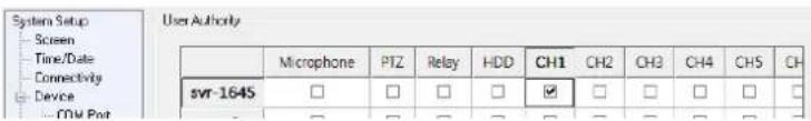
text_image
System Setup Screen Time/Date Connectivity Device - CPU Port User Authority Microphone PTZ Relay HDD CH1 CH2 CH3 CH4 CH5 CH svr-164S □ □ □ □ ☑ □ □ □ □ □ □ - □ □ □ □ □ □ □ □ □ □ □ □7.4 Supported Browser
Web Viewer is optimized to Windows Internet Explorer 6.0 and higher.
Web viewer Installer
The installation program necessary to use Web Viewer is provided at the login page. For computers without ActiveX, Web Viewer will install ActiveX to allow Web Viewer's functions to work as intended.

Please close all programs related to Network Manager before installing Web
Viewer. Failure to do so may result in malfunction.
7.5 Monitor
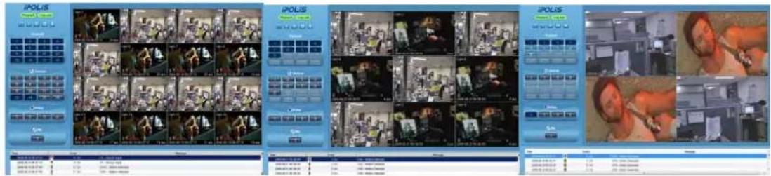
text_image
Screenshot of a video surveillance system interface displaying multiple video frames with Chinese text labels and UI elements.Once provided with the correct ID and password combination, Web Viewer will automatically move to the monitoring page. The monitoring page is used to watch live visual feed or to perform other functions allowed with the account's authority level.
Detailed explanation and description of the features of the monitoring page is as follow.
7.5.1 Screen Partition & Image Movement
The monitoring page will display a partition mode according to the model.

Using the buttons shown above, the partition mode may shift from Single, 4, 9, 13 and 16 partitions. Clicking the monitoring area will change the partition mode to Single.
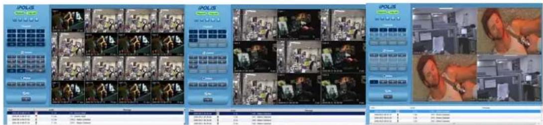
text_image
Screenshot of a video surveillance system interface displaying multiple video frames with Chinese text labels and UI elements.Double-click the channel to expand into Single partition mode.
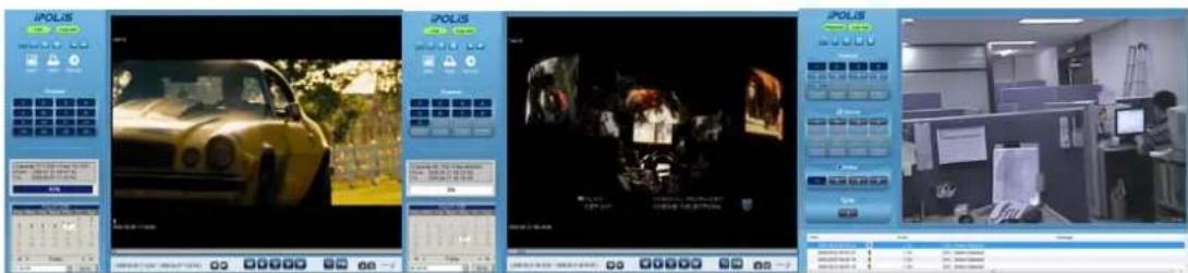
text_image
Screenshot of a video editing interface with multiple panels showing car navigation, status bar, and office environmentThe screen will expand into Single partition. To return to the partition screen, double-click the monitoring area once again. In a partition mode, the placement of screens may be moved around. To move Ch.3 to where Ch.6 currently is, drag and drop the partition corresponding to
Ch.3 over Ch.6 to switch their places.
7.5.2 Moving Playback

Click the "Playback" button shown above to move to the playback page.
7.5.3 Channel On/Off

text_image
Channel 1 2 3 4 5 7 8 8 9 10 11 12 13 14 15 16 Channel 1 2 3 4 5 6 7 8 9 0 1 2 13 2 15 16 Channel 1 2 3 4 5 6 7 8 9 10 11 12 13 14 15 16Channel On/Off buttons are located to the left of the page. Click the channels to toggle between On and Off. The default value for all channels is On.

text_image
Channel 1 2 3 4 5 6 7 8 9 10 11 12 13 14 15 16 Channel 1 2 3 4 5 6 7 8 9 10 11 12 13 14 15 16 Channel 1 2 3 4 5 6 7 8 9 10 11 12The above illustration displays the result of toggling Ch.8 and 9 off. When turned off, buttons will change color and the corresponding screen will fade to black. Deactivated buttons are channels not supported by the DVR model.
7.5.4 Sensor indication
This icon indicates that a sensor has been triggered.

text_image
Sensor 1 2 3 4 5 6 7 8 9 10 11 12 13 14 15 16 Sensor 1 2 3 4 5 6 7 8 9 10 11 12 13 14 15 16 Sensor 1 2 3 4When triggered, its corresponding icon will turn red and the sensor ID number will be displayed on the video. Sensors that have not been triggered will remain blue.

text_image
Cam 2 9 19 2008.08.07 11:06:46 25 ipsDeactivated sensor icons are sensors not supported by the DVR model.
7.5.5 Relay operation
The product's Relay can be set to On or Off. Clicking a relay button will set the corresponding relay to On and change the button's color from blue to orange.

text_image
Relay 1 2 3 4 Relay 1 2 3 4Deactivated relay buttons are relays not supported by the DVR model. Relay actions require a specific authority level. Consult the manual on how to configure relay authority level.
7.5.6 Microphone use

Microphone usage may be set to On or Off. The default value is Off. Clicking the button will depress the button and toggle the usage status.

Deactivated Mic. button means that the model does not support this function.
7.5.7 Event Data
| Time | Event | Message |
| 2000.09.19/06 09:23 | 4 On | Onit - Motion Deferring |
| 2000.09.19/06 07:18 | 12 On | Onit-2 - Motion Deferring |
| 2000.09.19/06 07:10 | 14 On | 14 - Sensor Input |
| 2000.09.19/06 07:16 | 12 On | 12 - Sensor Input |
A real-time log of event information is displayed below the monitoring page. Items found in this log are as shown below. (Table Event Icon)
| Button | Function |
| Change setup | |
| Motion detection | |
| Sensor | |
| Relay On | |
| V-loss | |
| Text Input | |
| User Login |
7.5.8 Video Recording & Video Storage
7.5.8.1 Video Recording
To record the visual data from the monitoring mode, select the channel, right-click and select "Rec Start". Up to 10 minutes of video may be recorded in this manner. If a Quick Recording operation is executed, the duration of the recording will be displayed on the

natural_image
Street view from two different locations: one showing a multi-story building with visible signage, the other showing a multi-story street with traffic and buildings (no readable text or symbols)Selecting "Rec Stop" while recording will conclude the recording operation. A dialogue window regarding the file location will be prompted and the user may save the file in any desired directory. The recording will save as a .re4 file, which can be played in NETWORK MANAGER Playback Program or a Mini-Player.
7.5.8.2 Save Image
The visual image may be saved as a .jpg, .bmp or .eye file and will save the frame currently displayed on the monitoring screen. To save an image, right-click the channel to save image from and select "Save As". To confirm the saving operation, go to the directory the image is saved to and double-click the image.
7.5.9 PTZ Use
While monitoring, right-clicking on a channel supporting PTZ and selecting "PTZ" will allow the user to manipulate the camera position.

natural_image
Street scene with motorcyclists and pedestrians, no visible text or signagePan, Tilt Control
To control PTZ, right-click the channel to manipulate and select "PTZ". A white cross will appear at the center of the screen. Click on the screen to manipulate camera position. Clicking left or right of the cross will pan the camera and above or below will tilt it. Clicking further from the camera will cause the camera to change its position faster.
Zoom, Focus Control
Placing the cursor at the left and right sides of the screen will reveal the zoom and focus slide bars. A camera unit supporting Area Zoom In will also support the Zoom Zero button. Use the slide bar to the left to zoom in and out and the right slide bar to control focus.
PTZ Home
If a preset position is configured, right-click during PTZ mode and select the desired preset position from "Goto Preset". The camera will move to the preset position. Preset positions must have been configured beforehand.
Auxiliary Operation
If a preset position has been configured, the pop-up menu will also contain "Auxiliary". Selecting the item will perform the assigned action.

For detailed explanation of the PTZ function and the list of supported cameras, please refer to "4.8 Manipulating PTZ".
7.5.10 Audio Use
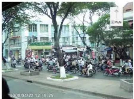
text_image
2008/04/22 12:35:25If a channel is paired with an audio channel, right-clicking the visual and selecting "Listen" from the pop-up menu will activate audio input. Also, to listen to the audio signal, Mute also needs to be unchecked.
7.5.11 Image Channel Close

text_image
Channel 1 2 3 4 5 7 8 8 9 10 11 12 13 14 15 16 Channel 1 2 3 4 5 6 7 8 9 10 11 12 13 14 15 16 Channel 1 2 3 4 5 6 7 8 9 10 11 12 13 14 15 16Clicking the channel buttons to the left of the screen will disconnect the visual connection and fade to black. To reconnect the channel, click the off channel button again.
7.6 Playback
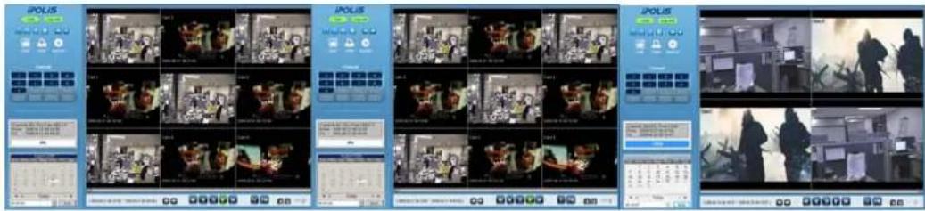
text_image
Screenshot of a video editing interface displaying multiple video thumbnails and UI elements for IPOLIS, with Chinese text labels.Recorded data can be reviewed in the playback mode. Only users with HDD access may use this mode. The playback mode uses 16 Partition screens and supports searches by time, calendar and cycle. Also, paused streams may be printed or saved as .bmp image files. Detailed explanation and description of the features of the playback page is as follow.
7.6.1 Screen Division & Channel Change

Playback supports 1, 4, 9 and 16 Partition modes. Use the menu (shown above) at the top of the page to choose a partition mode. When the monitoring screen is displaying Channel 1 through 4 in 4 Partition mode, clicking ">>" button will display the next four channels. To return to the previous four channels, click "<<".

7.6.2 Image Recording

A frame from a playback can be saved as a .bmp image file. Click the channel to capture and click "Save".

text_image
Save Image Memo SVR: 5445 Save Test Name Date Event OK CancelA Save Image dialogue window will pop up. A brief memo on the image can be saved with it. Click "OK" to prompt save location window.
7.6.3 Print
Printing a channel is similar to capturing a frame. Click the channel to print and click "Print".
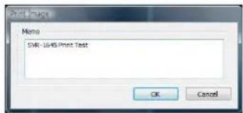
text_image
Serial Image Menu SNR: 1645 Print Test OK CancelType the relevant memo and click "OK" to print the image. The print will contain the printing date, channel name, recording date, event and memo.
7.6.4 Move to Web Monitor

To move to Web Monitor, click "Monitor" at the top left of the page.
7.6.5 Channel On/Off
This function is identical to the Web Monitor counterpart. The Channel On/Off buttons are at the right side of the page and clicking them will turn the channels on and off. The default value is On. Deactivated channel buttons are not supported by the DVR model.
7.6.6 Recording Duration & Recording Size Check
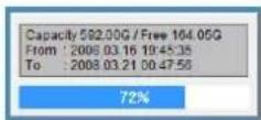
This menu displays used and remaining spaces in the HDD. It also displays the total recording duration. HDD usage is expressed as a percentage.
7.6.7 Calendar Search

text_image
Sun Mon Tue Wed Thu Fri Sat 2 3 4 5 6 7 8 9 10 11 12 13 14 15 16 17 18 19 20 21 22 23 24 25 26 27 28 29 30 31 Today 19:43:35 Go toDays with recordings are activated as black buttons and days without recordings are gray and deactivated. To review the recording, select the date and time of the recording and click to play the recording from the specified timeframe.

Clicking "Go To (Go to)" will display the timeframe of 24 hours beginning from the date and time specified above at the bottom left. Click "24h" to adjust the timeframe.
7.6.8 Playback Toolbar

text_image
[2008.03.03 10:45:44 ~ 2008.03.03 10:49:15] (1) (2) (3) (4) (5) (6) (7)① Displays the recording duration.
② Shifts through the time frame by an interval set by (5).
③ From left to right: "Move back 1 frame", "Play backward", "Pause", "Play" and "Move forward 1 frame"
④ Sets the standard video speed. Click the button and choose from 0.5x, 1x, 2x, 4x, 16x, 32x, 64x and All.
⑤ Sets the shift interval. Click the button and choose from 10 min, 30 min, 1 hour, 3 hour, 6 hour, 12 hour and 24 hour.
⑥ Toggles DirectX usage. If enabled, the video will be drawn with DirectDraw and improve the quality depending on the PC's specification.
⑦ Controls the volume
Trouble Shooting
1. DVR is not booting up
- Check the power supply
- Check the power cord
2. Monitor won't display anything
- Check the monitor's power supply
-
Check the connection between the DVR and the monitor
-
Check the monitor's cable port
- Check whether DVR is turned on
- If the images are in black and white, check the camera type (NTSC/PAL) and reboot
3. Some channels are dead
- Check the camera's power supply
- Check the camera's input status
- Check the DVR's input port
- Check the Activity setting under the Screen menu
- Check the Covert setting under the Monitor menu
4. The video won't record
- Check for the HDD connection status from Disk Manager
- Check the Recording settings
5. The recordings won't play
- Check the Recording settings
- Check the button activity
6. Images are too dark or bright
- Check the camera's configuration
- Separate the visual input cable from power supplies
- Check the Brightness and Contrast settings under the Screen menu
7. The remote won't work
- Check the batteries
- Check the remote's ID
- Check the remote's specification
8. The buttons aren't working
- Check the DVR's power supply
- Check the Screen Lock setting
9. The DVR won't connect to the network
- Check whether the network cable is connected properly
-
Check the DVR's IP
-
Check the PC's IP
- Ping Test
- Check the PC's specification if Web Viewer will not run properly
10. Cases to contact purchasing agency
If the following cases occur, immediately cease the product operation, shut off the power supply and take the console to the purchasing agency for repair.
● The product malfunctions during operation (Ex.: Strange noise, smell, smoke, etc.)
● The power cable or the connector has been damaged.
● The product has been flooded.
● The product has been spilled on.
● The product will not function as stated in this document.
● The product was severely damaged due to physical shock.
● A stark change in performances has been noticed.
Compatible HDD List
| Western Digital | |
| Capacity | Model |
| 1000GB | WD10EVCS |
| 750GB | WD7500AVCS |
| 500GB | WD5000AVVS |
| 320GB | WD3200AVVS |
Compatible Media List
| DVD-R manufacture CD-R manufacture | |
| Mitsubishi(Exhortation 16X) Mitsubishi(Exhortation 16X) | |
| TDK(Exhortation 16X) TDK(Exhortation 16X) | |
| Imation(Exhortation 16X) Imation(Exhortation 16X) | |
| Sony(Exhortation 16X) Sony(Exhortation 16X) |
Specification
| Item Description | ||
| Display | ||
| Video | Inputs | SVR-3200 : 32 composite video 0.5–2 Vpp, 75 ohm automatic terminationSVR-1680C/1660C/1645 : 16 composite video 0.5–2 Vpp, 75 ohm automatic terminationSVR-960C/945 : 9 composite video 0.5–2 Vpp, 75 ohm automatic terminationSVR-480 : 4 composite video 0.5–2 Vpp, 75 ohm automatic termination |
| Resolution | 704x480 NTSC | |
| Live | Frame rate | SVR-3200 : NTSC(960Cfps), PAL(800fps)SVR-1680C/1660C/1645 : NTSC(480fps),PAL(400fps)SVR-960C/945 : NTSC(270fps), PAL(225fps)SVR-480 : NTSC(120fps), PAL(100fps) |
| Resolution 704x480 NTSC, 704x576 PAL | ||
| SVR-3200/1680C/1660C/1645 : 1/4/9/10/16SVR-960C/945 : 1/4/9SVR-480 : 1/4 | ||
| Performance | ||
| Recording | Compression MPEG-4 | |
| Record Rate/NTSC | SVR-3200: 480fps@704x480, 960Cfps@704x240, 960Cfps@352x240SVR-1680C: 480fps@704x480, 480fps@704x240, 480fps@352 x 240SVR-1660C/1645: 120fps@704x480, 240fps@704x240, 480fps@352x240SVR-960C/945: 120fps@704x480, 240fps@704x240, 270fps@352x240SVR-480: 120fps@704x480, 120fps@704x240, 120fps@352x240 | |
| Record | SVR-3200: 400fps@704x576, 800fps@704x288, 800fps@352x288SVR-1680C: 400fps@704x576, 400fps@704x288, 400fps@352x288Rate/PALSVR-1660C/1645: 100fps@704x576, 200fps@704x288, 400fps@352x288SVR-960C/945: 100fps@704x576, 200fps@704x288, 225fps@352x288SVR-480: 100fps@704x576, 100fps@704x288, 100fps@352x288 | |
| Mode Manual, Schedule, | Event, Emergency | |
| Overwrite | modes Continuous | |
| to 5 sec. | ||
| to 60 sec. | ||
| Search &PlaybackFrame rate 480 | Search mode | Date/time, Event, Calendar, Thumbnail, Bookmark Text(Exclusive viewer) |
| fps D1 NTSC, 400 fps D1 | PAL | |
| Playback | REW, FWD, Frame advance (control keys and jog function shuttle) | |
| Network | Transmission speed SVR-3200/1680C: 16 Mbps | |
| Multi Stream MRemote Users | SVR-1660C/1645/960C/945/480 : 9 Mbps | ||
| Bandwidth | control | Automatic | |
| PEG-4(Dual Streams)/JPEG | |||
| Up to 10 simultaneous users | |||
| Protocol | TCP/IP, DHCP, DNS, DDNS, HTTP, ARP, ICMP support and NTP | ||
| Monitoring | CMS | Software(SNM-128S/P), Built-in web server | |
| StorageDVD Writer (Back-up)USB (Back-up)File Format | Maximum Capacity | SVR-3200/1680C/1660C : 16 TBSVR-1645/960C/945/480 : 8 TB | |
| Internal HDD | SVR-3200/1680C/1660C : 4 HDDSVR-1645/960C/945/480 : 2 HDD | ||
| External | SVR-3200/1680C/1660C : External eSATA 2 portHDDSVR-1645/960C/945/480 : External eSATA 1 port | ||
| Back-up) DVD-R / CD-R | |||
| 2 External USB Ports(USB | 2.0) | ||
| (Back-up) | BMP, AVI, Proprietary format / JPG(Exclusive viewer) | ||
| Security | Password Protection 10 User Level | ||
| Data Authentication Watermark | |||
| Interface | |||
| MonitorsMain Composite | VGA | Analog RGB 800x600, 1024x768, 1280x1024 resolution | |
| BNC, 1 Vp-p, 75 ohm, Multi-screen, Menu, Playback | |||
| Sub Composite | Monitor2~4 : SVR-3200/1680C(Menu, Event Pop-up, Covert, Display Switching)Sport : SVR-1660C/1645/960C/945/480(event Pop-up, Display switching), 1 Vp-p, 75 ohm | ||
| Loop Outputs | SVR-3200 : NoneSVR-1680C/1660C/1645 : 16 Output, 1 Vpp, 75 outputsSVR-960C/945 : 9 Output, 1 Vpp, 75 ohmSVR-480 : 4 Output, 1 Vpp, 75 ohm | ||
| AudioOutput | Inputs | SVR-3200/1680C/1660C/1645 : 16 input, 30k ohmSVR-960C/945 : 9 input | |
| 1 line, 100k ohm | |||
| Compression | ADPCM | ||
| Sampling rate | 16 kHz | |
| Alarm | Inputs | SVR-3200/1680C/1660C/1645 : 16 Input, NO/NCSVR-960C/945 : 9 InputSVR-480 : 4 Input |
| Outputs | Screw terminal 4 relay outputs, NO/NC(SVR-480 : Screw terminal 2 relay outputs, NO/NC) | |
| Remote notification | Notification via e-mail | |
| Connections | Ethernet RJ45 10/100 | Base-T |
| Serial interface | RS232 | |
| PTZ control interface | SVR-3200/1680C/1660C : RS485/RS422SVR-1645/960C/945/480 : RS485Via coax cable (SVR-1680C/1660C/960C) | |
| PTZ KeyboardUSB 2 USB 2 | RS485, max. signal voltage ±12 V | |
| 0 ports | ||
| eSATA | SVR-3200/1680C/1660C : External eSATA 2 portSVR-1645/960C/945/480 : External eSATA 1 port | |
| Application Support | port ATM/POS, Mouse, Remote Controller | |
| DomeProtocols | Supported PTZ cameras | Samsung Techwin, Pelco D, Pelco P, PelcoCoaxitron, Panasonic, Bosch, SEC |
| General | ||
| Electrical | Input Voltage 100 to 240 VAC ±10%; 50/60 Hz, Auto-ranging | |
| Power consumptionMax. 90 W (with 4x HDD) | Max. 65 W (with 1x HDD)Max. 88 W (with 2x HDD) | |
| Environmental | Operating Temperature | +5°C to +40°C (+32°F to +104°F) |
| Operating Humidity | 0% RH to 60% RH | |
| Mechanical | Dimensions (W x H x D) | 445 x 88 x 388 mm (17.5 x 3.5 x 15.3 in)SVR-945 : 300 x 88 x 302 mm(118.11 x 34.65 x 130.7 in)SVR-480 : 350 x 88 x 401.3 mm(13.77 x 3.46 x 15.79 in) |
| Weight (1x hard disks) | Approx. 10 kg (22.1 lb), SVR-945 : 5 kg (11 lb)SVR-480 : 5.6kg | |
| Rack mount kit | For mounting one unit in an EIA 19-inch rack(SVR-945 Stand type) | |
| Language | English, Spanish, French, German, Italian, Polish, | |
| Portuguese, Russian, Turkish, Japanese, Czech, Serbian, Swedish, Rumanian, Danish, Chinese, Korean, Taiwanese | ||
Dimensions
SVR-3200, SVR-1680C, SVR-1660C, SVR-1645
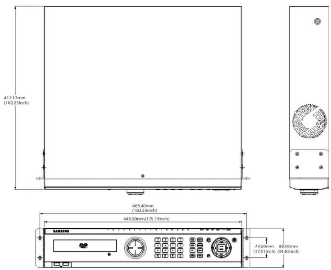
SVR-960C
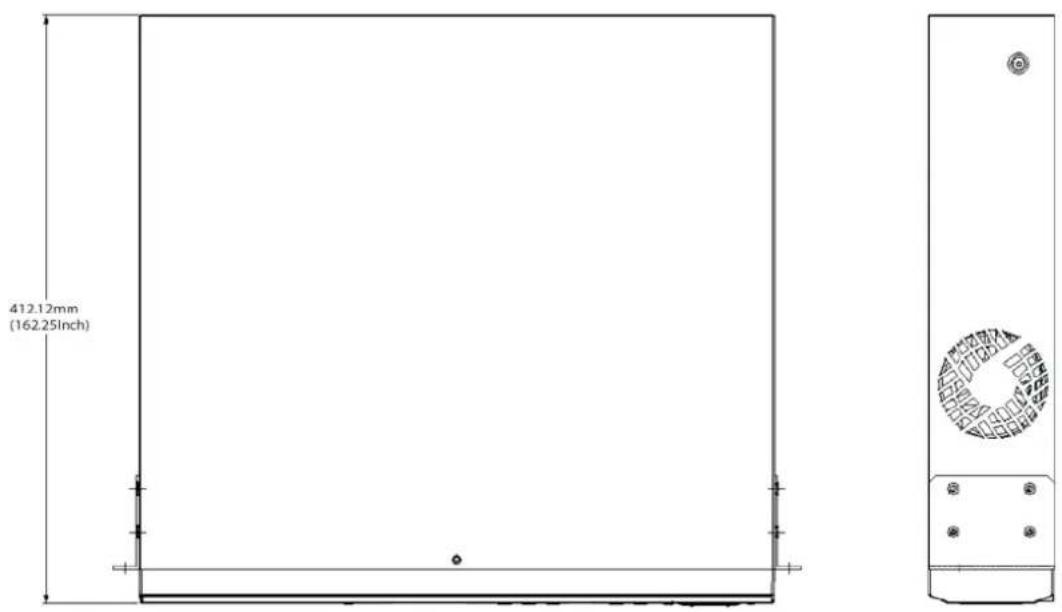
text_image
412.12mm (162.25Inch)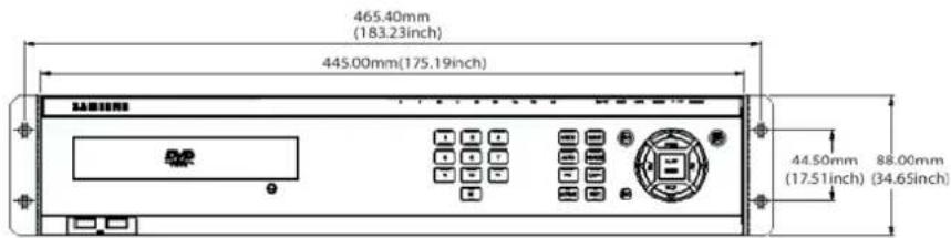
text_image
465.40mm (183.23inch) 445.00mm(175.19inch) 44.50mm 88.00mm (17.51inch) (34.65inch)SVR-945
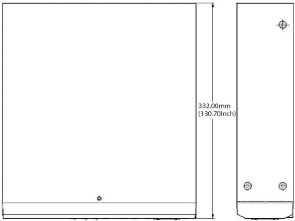
text_image
332.00mm (130.70Inch)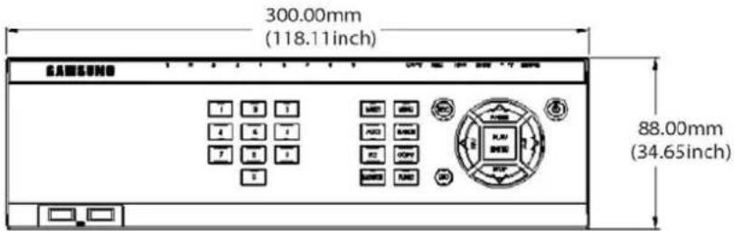
text_image
300.00mm (118.11inch) SAMSUNG 88.00mm (34.65inch)SVR-480
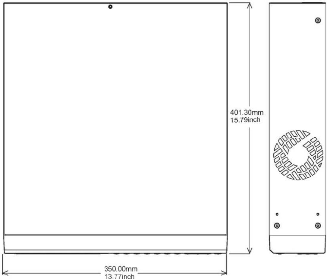
text_image
401.30mm 15.79inch 350.00mm 13.77inch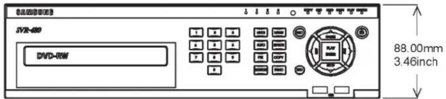
text_image
SAMSUNG SVR-400 DVD-RW 88.00mm 3.46inchThis product uses some Software programs which are distributed under the GNU GPL(General Public License)/LGPL license, and the program is licensed as is without warranty of any kind. The program can be obtained from us for a period of three years after our last distribution of this product by sending email to help.cctv@samsung.com. If you want to obtain the complete Corresponding Source Code in the physical medium such as CD-ROM by airmail, the cost of physically performing source distribution might be charged. This offer is valid to anyone in receipt of this information. For more additional information visit http://samsungcctv.com/gpl
GPL Software : linux kernel, busybox, boa, dhcpcd, iproute2, rp-pppoe, smartsuite.
GNU GENERAL PUBLIC LICENSE
Version 2, June 1991
Copyright (C) 1989, 1991 Free Software Foundation, Inc.
51 Franklin Street, Fifth Floor, Boston, MA 02110-1301, USA
Everyone is permitted to copy and distribute verbatim copies of this license document, but changing it is not allowed.
Preamble
The licenses for most software are designed to take away your freedom to share and change it. By contrast, the GNU General Public License is intended to guarantee your freedom to share and change free software--to make sure the software is free for all its users. This General Public License applies to most of the Free Software Foundation's software and to any other program whose authors commit to using it. (Some other Free Software Foundation software is covered by the GNU Lesser General Public License instead.) You can apply it to your programs, too.
When we speak of free software, we are referring to freedom, not price. Our General Public Licenses are designed to make sure that you have the freedom to distribute copies of free software (and charge for this service if you wish), that you receive source code or can get it if you want it, that you can change the software or use pieces of it in new free programs; and that you know you can do these things.
To protect your rights, we need to make restrictions that forbid anyone to deny you these rights or to ask you to surrender the rights. These restrictions translate to certain responsibilities for you if you distribute copies of the software, or if you modify it.
For example, if you distribute copies of such a program, whether gratis or for a fee, you must give the recipients all the rights that you have. You must make sure that they, too, receive or can get the source code. And you must show them these terms so they know their rights.
We protect your rights with two steps: (1) copyright the software, and (2) offer you this license which gives you legal permission to copy, distribute and/or modify the software.
Also, for each author's protection and ours, we want to make certain that everyone understands that there is no warranty for this free software. If the software is modified by someone else and passed on, we want its recipients to know that what they have is not the original, so that any problems introduced by others will not reflect on the original authors' reputations.
Finally, any free program is threatened constantly by software patents. We wish to avoid the danger that redistributors of a free program will individually obtain patent licenses, in effect making the program proprietary. To prevent this, we have made it clear that any patent must be licensed for everyone's free use or not licensed at all.
The precise terms and conditions for copying, distribution and modification follow.
TERMS AND CONDITIONS FOR COPYING, DISTRIBUTION AND MODIFICATION
- This License applies to any program or other work which contains a notice placed by the copyright holder saying it may be distributed under the terms of this General Public License. The "Program", below, refers to any such program or work, and a "work based on the Program" means either the Program or any derivative work under copyright law: that is to say, a work containing the Program or a portion of it, either verbatim or with modifications and/or translated into another language. (Hereinafter, translation is included without limitation in the term "modification".) Each licensee is addressed as "you".
Activities other than copying, distribution and modification are not covered by this License; they are outside its scope. The act of running the Program is not restricted, and the output from the Program is covered only if its contents constitute a work based on the Program (independent of having been made by running the Program). Whether that is true depends on what the Program does.
- You may copy and distribute verbatim copies of the Program's source code as you receive it, in any medium, provided that you conspicuously and appropriately publish on each copy an appropriate copyright notice and disclaimer of warranty; keep intact all the notices that refer to this License and to the absence of any warranty; and give any other recipients of the Program a copy of this License along with the Program.
You may charge a fee for the physical act of transferring a copy, and you may at your option offer warranty protection in exchange for a fee.
- You may modify your copy or copies of the Program or any portion of it, thus forming a work based on the Program, and copy and distribute such modifications or work under the terms of Section 1 above, provided that you also meet all of these conditions:
a) You must cause the modified files to carry prominent notices stating that you changed the files and the date of any change.
b) You must cause any work that you distribute or publish, that in whole or in part contains or is derived from the Program or any part thereof, to be licensed as a whole at no
charge to all third parties under the terms of this License.
c) If the modified program normally reads commands interactively when run, you must cause it, when started running for such interactive use in the most ordinary way, to print or display an announcement including an appropriate copyright notice and a notice that there is no warranty (or else, saying that you provide a warranty) and that users may redistribute the program under these conditions, and telling the user how to view a copy of this License. (Exception: if the Program itself is interactive but does not normally print such an announcement, your work based on the Program is not required to print an announcement.)
These requirements apply to the modified work as a whole. If identifiable sections of that work are not derived from the Program, and can be reasonably considered independent and separate works in themselves, then this License, and its terms, do not apply to those sections when you distribute them as separate works. But when you distribute the same sections as part of a whole which is a work based on the Program, the distribution of the whole must be on the terms of this License, whose permissions for other licensees extend to the entire whole, and thus to each and every part regardless of who wrote it.
Thus, it is not the intent of this section to claim rights or contest your rights to work written entirely by you; rather, the intent is to exercise the right to control the distribution of derivative or collective works based on the Program.
In addition, mere aggregation of another work not based on the Program with the Program (or with a work based on the Program) on a volume of a storage or distribution medium does not bring the other work under the scope of this License.
- You may copy and distribute the Program (or a work based on it, under Section 2) in object code or executable form under the terms of Sections 1 and 2 above provided that you also do one of the following:
a) Accompany it with the complete corresponding machine-readable source code, which must be distributed under the terms of Sections 1 and 2 above on a medium customarily used for software interchange; or,
b) Accompany it with a written offer, valid for at least three years, to give any third party, for a charge no more than your cost of physically performing source distribution, a complete machine-readable copy of the corresponding source code, to be distributed under the terms of Sections 1 and 2 above on a medium customarily used for software interchange; or,
c) Accompany it with the information you received as to the offer to distribute corresponding source code. (This alternative is allowed only for noncommercial distribution and only if you received the program in object code or executable form with
such an offer, in accord with Subsection b above.)
The source code for a work means the preferred form of the work for making modifications to it. For an executable work, complete source code means all the source code for all modules it contains, plus any associated interface definition files, plus the scripts used to control compilation and installation of the executable. However, as a special exception, the source code distributed need not include anything that is normally distributed (in either source or binary form) with the major components (compiler, kernel, and so on) of the operating system on which the executable runs, unless that component itself accompanies the executable.
If distribution of executable or object code is made by offering access to copy from a designated place, then offering equivalent access to copy the source code from the same place counts as distribution of the source code, even though third parties are not compelled to copy the source along with the object code.
-
You may not copy, modify, sublicense, or distribute the Program except as expressly provided under this License. Any attempt otherwise to copy, modify, sublicense or distribute the Program is void, and will automatically terminate your rights under this License. However, parties who have received copies, or rights, from you under this License will not have their licenses terminated so long as such parties remain in full compliance.
-
You are not required to accept this License, since you have not signed it. However, nothing else grants you permission to modify or distribute the Program or its derivative works. These actions are prohibited by law if you do not accept this License. Therefore, by modifying or distributing the Program (or any work based on the Program), you indicate your acceptance of this License to do so, and all its terms and conditions for copying, distributing or modifying the Program or works based on it.
-
Each time you redistribute the Program (or any work based on the Program), the recipient automatically receives a license from the original licensor to copy, distribute or modify the Program subject to these terms and conditions. You may not impose any further restrictions on the recipients' exercise of the rights granted herein. You are not responsible for enforcing compliance by third parties to this License.
-
If, as a consequence of a court judgment or allegation of patent infringement or for any other reason (not limited to patent issues), conditions are imposed on you (whether by court order, agreement or otherwise) that contradict the conditions of this License, they do not excuse you from the conditions of this License. If you cannot distribute so as to satisfy simultaneously your obligations under this License and any other pertinent obligations, then as a consequence you may not distribute the Program at all.
For example, if a patent license would not permit royalty-free redistribution of the Program by all those who receive copies directly or indirectly through you, then the only way you
could satisfy both it and this License would be to refrain entirely from distribution of the Program.
If any portion of this section is held invalid or unenforceable under any particular circumstance, the balance of the section is intended to apply and the section as a whole is intended to apply in other circumstances.
It is not the purpose of this section to induce you to infringe any patents or other property right claims or to contest validity of any such claims; this section has the sole purpose of protecting the integrity of the free software distribution system, which is implemented by public license practices. Many people have made generous contributions to the wide range of software distributed through that system in reliance on consistent application of that system; it is up to the author/donor to decide if he or she is willing to distribute software through any other system and a licensee cannot impose that choice.
This section is intended to make thoroughly clear what is believed to be a consequence of the rest of this License.
-
If the distribution and/or use of the Program is restricted in certain countries either by patents or by copyrighted interfaces, the original copyright holder who places the Program under this License may add an explicit geographical distribution limitation excluding those countries, so that distribution is permitted only in or among countries not thus excluded. In such case, this License incorporates the limitation as if written in the body of this License.
-
The Free Software Foundation may publish revised and/or new versions of the General Public License from time to time. Such new versions will be similar in spirit to the present version, but may differ in detail to address new problems or concerns.
Each version is given a distinguishing version number. If the Program specifies a version number of this License which applies to it and "any later version", you have the option of following the terms and conditions either of that version or of any later version published by the Free Software Foundation. If the Program does not specify a version number of this License, you may choose any version ever published by the Free Software Foundation.
- If you wish to incorporate parts of the Program into other free programs whose distribution conditions are different, write to the author to ask for permission. For software which is copyrighted by the Free Software Foundation, write to the Free Software Foundation; we sometimes make exceptions for this. Our decision will be guided by the two goals of preserving the free status of all derivatives of our free software and of promoting the sharing and reuse of software generally.
NO WARRANTY
- BECAUSE THE PROGRAM IS LICENSED FREE OF CHARGE, THERE IS NO WARRANTY FOR THE PROGRAM, TO THE EXTENT PERMITTED BY APPLICABLE LAW. EXCEPT WHEN OTHERWISE STATED IN WRITING THE COPYRIGHT HOLDERS
AND/OR OTHER PARTIES PROVIDE THE PROGRAM "AS IS" WITHOUT WARRANTY OF ANY KIND, EITHER EXPRESSED OR IMPLIED, INCLUDING, BUT NOT LIMITED TO, THE IMPLIED WARRANTIES OF MERCHANTABILITY AND FITNESS FOR A PARTICULAR PURPOSE. THE ENTIRE RISK AS TO THE QUALITY AND PERFORMANCE OF THE PROGRAM IS WITH YOU. SHOULD THE PROGRAM PROVE DEFECTIVE, YOU ASSUME THE COST OF ALL NECESSARY SERVICING, REPAIR OR CORRECTION.
12. IN NO EVENT UNLESS REQUIRED BY APPLICABLE LAW OR AGREED TO IN WRITING WILL ANY
COPYRIGHT HOLDER, OR ANY OTHER PARTY WHO MAY MODIFY AND/OR REDISTRIBUTE THE PROGRAM AS PERMITTED ABOVE, BE LIABLE TO YOU FOR DAMAGES, INCLUDING ANY GENERAL, SPECIAL, INCIDENTAL OR CONSEQUENTIAL DAMAGES ARISING OUT OF THE USE OR INABILITY TO USE THE PROGRAM (INCLUDING BUT NOT LIMITED TO LOSS OF DATA OR DATA BEING RENDERED INACCURATE OR LOSSES SUSTAINED BY YOU OR THIRD PARTIES OR A FAILURE OF THE PROGRAM TO OPERATE WITH ANY OTHER PROGRAMS), EVEN IF SUCH HOLDER OR OTHER PARTY HAS BEEN ADVISED OF THE POSSIBILITY OF SUCH DAMAGES.
GNU LESSER GENERAL PUBLIC LICENSE
Version 3, 29 June 2007
Copyright (C) 2007 Free Software Foundation, Inc. http://fsf.org/ Everyone is permitted to copy and distribute verbatim copies of this license document, but changing it is not allowed.
This version of the GNU Lesser General Public License incorporates the terms and conditions of version 3 of the GNU General Public License, supplemented by the additional permissions listed below.
0. Additional Definitions.
As used herein, "this License" refers to version 3 of the GNU Lesser General Public License, and the "GNU GPL" refers to version 3 of the GNU General Public License.
"The Library" refers to a covered work governed by this License, other than an Application or a Combined Work as defined below.
An "Application" is any work that makes use of an interface provided by the Library, but which is not otherwise based on the Library. Defining a subclass of a class defined by the Library is deemed a mode of using an interface provided by the Library.
A "Combined Work" is a work produced by combining or linking an Application with the Library. The particular version of the Library with which the Combined Work was made is also called the "Linked Version".
The "Minimal Corresponding Source" for a Combined Work means the Corresponding Source for the Combined Work, excluding any source code for portions of the Combined Work that, considered in isolation, are based on the Application, and not on the Linked Version.
The "Corresponding Application Code" for a Combined Work means the object code and/or source code for the Application, including any data and utility programs needed for reproducing the Combined Work from the Application, but excluding the System Libraries of the Combined Work.
- Exception to Section 3 of the GNU GPL.
You may convey a covered work under sections 3 and 4 of this License without being bound by section 3 of the GNU GPL.
- Conveying Modified Versions.
If you modify a copy of the Library, and, in your modifications, a facility refers to a function or data to be supplied by an Application that uses the facility (other than as an argument passed when the facility is invoked), then you may convey a copy of the modified version:
a) under this License, provided that you make a good faith effort to ensure that, in the event an Application does not supply the function or data, the facility still operates, and performs whatever part of its purpose remains meaningful, or b) under the GNU GPL, with none of the additional permissions of this License applicable to that copy.
- Object Code Incorporating Material from Library Header Files.
The object code form of an Application may incorporate material from a header file that is part of the Library. You may convey such object code under terms of your choice, provided that, if the incorporated material is not limited to numerical parameters, data structure layouts and accessors, or small macros, inline functions and templates (ten or fewer lines in length), you do both of the following:
a) Give prominent notice with each copy of the object code that the Library is used in it and that the Library and its use are covered by this License.
b) Accompany the object code with a copy of the GNU GPL and this license document.
4. Combined Works.
You may convey a Combined Work under terms of your choice that, taken together, effectively do not restrict modification of the portions of the Library contained in the Combined Work and reverse engineering for debugging such modifications, if you also do each of the following:
a) Give prominent notice with each copy of the Combined Work that the Library is used in and that the Library and its use are covered by this License.
b) Accompany the Combined Work with a copy of the GNU GPL and this license document.
c) For a Combined Work that displays copyright notices during execution, include the copyright notice for the Library among these notices, as well as a reference directing the user
to the copies of the GNU GPL and this license document.
d) Do one of the following:
0) Convey the Minimal Corresponding Source under the terms of this License, and the Corresponding Application Code in a form suitable for, and under terms that permit, the user to recombine or relink the Application with a modified version of the Linked Version to produce a modified Combined Work, in the manner specified by section 6 of the GNU GPL for conveying Corresponding Source.
1) Use a suitable shared library mechanism for linking with the Library. A suitable mechanism is one that (a) uses at run time a copy of the Library already present on the user's computer system, and (b) will operate properly with a modified version of the Library that is interface-compatible with the Linked Version.
e) Provide Installation Information, but only if you would otherwise be required to provide such information under section 6 of the GNU GPL, and only to the extent that such information is necessary to install and execute a modified version of the Combined Work produced by recombining or relinking the Application with a modified version of the Linked Version. (If you use option 4d0, the Installation Information must accompany the Minimal Corresponding Source and Corresponding Application Code. If you use option 4d1, you must provide the Installation Information in the manner specified by section 6 of the GNU GPL for conveying Corresponding Source.)
5. Combined Libraries.
You may place library facilities that are a work based on the Library side by side in a single library together with other library facilities that are not Applications and are not covered by this License, and convey such a combined library under terms of your choice, if you do both of the following:
a) Accompany the combined library with a copy of the same work based on the Library, uncombined with any other library facilities, conveyed under the terms of this License.
b) Give prominent notice with the combined library that part of it is a work based on the Library, and explaining where to find the accompanying uncombined form of the same work.
6. Revised Versions of the GNU Lesser General Public License.
The Free Software Foundation may publish revised and/or new versions of the GNU Lesser General Public License from time to time. Such new versions will be similar in spirit to the present version, but may differ in detail to address new problems or concerns.
Each version is given a distinguishing version number. If the Library as you received it specifies that a certain numbered version of the GNU Lesser General Public License "or any later version"
applies to it, you have the option of following the terms and conditions either of that published version or of any later version published by the Free Software Foundation. If the Library as you
received it does not specify a version number of the GNU Lesser General Public License, you may choose any version of the GNU Lesser General Public License ever published by the Free Software Foundation.
If the Library as you received it specifies that a proxy can decide whether future versions of the GNU Lesser General Public License shall apply, that proxy's public statement of acceptance of any version is permanent authorization for you to choose that version for the Library.
SAMSUNG TECHWIN

• SALES NETWORK
SAMSUNG TECHWIN CO.,LTD.
145-3, Sangdaewon-dong, Jungwon-gu, Seongnam-si, Gyeonggi-do, 462-120, Korea
TEL: +82-31-740-8151\~8 FAX: +82-31-740-8145
SAMSUNG TECHWIN EUROPE CO., LTD.
Samsung House, 1000 Hillswood Drive, Hillswood Business Park Chertsey, Surrey, UNITED KINGDOM KT16 OPS
TEL: +44-1932-45-5308 FAX: +44-1932-45-5325