SPM 6000 Mk2 - Receiver Chord - Free user manual and instructions
Find the device manual for free SPM 6000 Mk2 Chord in PDF.


| Product Type | Receiver |
| Brand | Chord |
| Model | SPM 6000 Mk2 |
| Dimensions (W x H x D) | 430 mm x 100 mm x 310 mm |
| Weight | 8.5 kg |
| Power Consumption | 180 W (standby <0.5 W) |
| Power Output (RMS) | 2 x 100 W (8 ohms) |
| Frequency Response | 20 Hz - 20 kHz ±0.5 dB |
| Total Harmonic Distortion | <0.05% |
| Signal-to-Noise Ratio | >95 dB |
| Inputs | 4x RCA, 1x Phono (MM), 1x Optical, 1x Coaxial |
| Outputs | Speaker terminals (stereo), 1x Pre-Out, 1x Headphone |
| Supported Audio Formats | PCM up to 24-bit/192 kHz, DSD64 |
| Remote Control | Included (IR) |
| Warranty | 2 years |
| Operating Temperature | 0°C to 35°C |
| Cleaning Instructions | Wipe with a soft, dry cloth. Do not use liquid cleaners. |
| Safety Precautions | Keep away from moisture, heat sources, and direct sunlight. Disconnect power during cleaning. |
| Spare Parts Availability | Contact Chord support or authorized service centers. |
| Repair Policy | Refer to warranty terms; out-of-warranty service available. |
Frequently Asked Questions - SPM 6000 Mk2 Chord
User questions about SPM 6000 Mk2 Chord
0 question about this device. Answer the ones you know or ask your own.
Ask a new question about this device
Download the instructions for your Receiver in PDF format for free! Find your manual SPM 6000 Mk2 - Chord and take your electronic device back in hand. On this page are published all the documents necessary for the use of your device. SPM 6000 Mk2 by Chord.
USER MANUAL SPM 6000 Mk2 Chord
Your amplifier should be positioned to ensure a free flow of air over the rear heat sink and through the upper and lower grilles. When driven continuously at well above average listening levels, the temperature on the heat sink may exceed 50^ C. This is not a fault, but an indication of the need for adequate ventilation.
Please ensure that the IEC mains lead is correctly terminated.
UK/EUROPE Brown = LIVE = Black USA/CANADA
Blue = NEUTRAL = White
Yellow/Green = EARTH = Green
THE SPM 6000 Mk 2 MUST BE EARTHED AT ALL TIMES VIA ITS OWN MAINS LEAD. FAILURE TO DO THIS MAY BE HAZARDOUS.
CE This unit complies with EN 50081-1 & IEC 801/2
It has come to light that, in some European countries a hum may occur if Pre and Power Amplifiers are connected to mains wall sockets which do not have an earth. Please ensure that, if this is the case, the pre and power amps are connected via a multi-way mains block which contains an earth point at each socket outlet. This is to ensure that the chassis metalwork of each item is connected together and Chord Electronics Limited firmly recommends that an earthing method for the building is implemented.
REAR PANEL
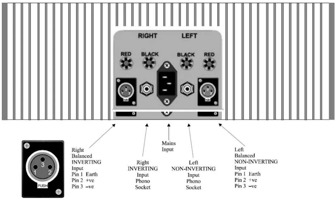
The rear of the SPM 6000 Mk 2 has two sets of inputs, one set of balanced XLR connections and one set of phono RCA connectors. You will also notice by looking at the diagram below that the inputs can be connected as either INVERTING or NON-INVERTING modes. Connecting to either the phono or the XLR on the right hand side will give an inverted output as is normal with other Chord amplification. However if a non-inverting output is preferred simply connect to the left hand side. As the SPM 6000 Mk 2 is of mono block construction only one of the inputs should be used. Where a pair of units is used for stereo operation the user should take care to connect both amplifiers in the same manner so as not to have an out of phase configuration. The input should be connected last, with the amplifier switched off.
There are two sets of high current gold plated output terminals, the speaker may be connected to either the left or the right set of terminals. For Bi-wiring configuration both sets of outputs can be used.
OPERATION
When the amplifier is connected to the mains the central clear ball will illuminate red (standby). Press the ball in to switch on the amplifier. The ball will illuminate green (operational). There will be a delay of about 12 seconds before the output signal is fed to the loudspeakers the ball will then change to blue to indicate the output relays are engaged.
In the event of a major overload or a short circuit across the output of any channel, the blue "power on" illumination will indicate trip by fading and immediately re-illuminating to red standby mode. The amplifier will shut down automatically and it should then be switched off at the mains outlet. When the fault condition has been rectified, the amplifier can be switched on and will power up as normal. A minimum period of 1 minute must be allowed to elapse between switching off and switching on again. This is to allow the power supply protection circuitry to re-set itself.
This amplifier is fitted with a trigger system designed to switch the unit on or off remotely.
N.B. with no plug inserted in the 12V trigger socket, the amplifier will operate as normal.
The external trigger should be connected to the amplifier via a standard 1/8^th inch / 3.5mm (mono or stereo) jack plug to the socket fitted to the rear of the unit.
The amplifier should be switched into the standby position (red illumination) and the 12V trigger lead inserted. The amplifier will now switch on when the trigger voltage is applied, and will switch off again when the voltage is removed (Positive Trigger). The front panel ball will indicate orange when the trigger is connected and change to purple when the trigger is operating to switch on the amplifier. You do not need to switch on the amplifier by pressing the ball on the front panel when the trigger is used – however it will still operate normally if you use the front panel button.
The connections are as follows:

The tip of the plug is the +5V to +12V dc connection, the centre and rear connection are the 0V or ground connection.
CARE AND CLEANING
The SPM 6000 Mk2 requires no special care other than common-sense. Spray window cleaner (clear type) may be used (if first sprayed on to a soft cloth) to remove surface blemishes such as finger marks from the metal casing or the wooden side cheeks (if fitted). Never spray directly on to the amplifier and never use abrasive cleaning materials, use only a lint free soft cloth as described.
SERVICE INFORMATION
There are no user serviceable parts in your SPM 6000 Mk2. It should only be serviced by Chord Electronics Limited or their expressly approved Service Agents.
WARNING - The power supply components within this amplifier are designed to be operated at lethal voltages and energy levels. Circuit designs that embody these components conform to applicable safety requirements. Precautions must be taken to prevent accidental contact with power-line potentials. Do not connect grounded test equipment.
| SPECIFICATIONS | SPM 6000 Mk2 POWER AMPLIFIER |
| OUTPUT POWER | 750W rms per channel @ 0.05% distortion into 8Ω,1500W rms per channel into 4 Ω, 3000W rms into 2Ω. Thermal limitation only, 1 channel driven. |
| DYNAMIC HEADROOM | 1000W rms per channel into 8Ω, 1800W rms per channel into 4Ω.- 1 KHz, 20 cycles on, 480 cycles off. Peak pulses 8 milliseconds burst |
| FREQUENCY RESPONSE (8 OHMS) | -1dB, 0.2Hz to 46KHz-3dB, 0.1Hz to 77KHz |
| FREQUENCY RESPONSE (4 OHMS) | -1dB, 0.2Hz to 39KHz-3dB, 0.1Hz to 75KHz |
| SIGNAL TO NOISE RATIO | Better than -103dB, ‘A’ weighted two thirds power. |
| CHANNEL SEPARATION | Better than 90dB. |
| PRE-AMPLIFIER INPUT CONNECTION | 2 x gold-plated, fully balanced XLR sockets. 2 x gold-plated custom phono sockets, unbalanced. |
| INPUT IMPEDANCE | 100kΩ. Unbalanced/Balanced. |
| INPUT CAPACITANCE | <30pf. |
| OUTPUT IMPEDANCE | 0.04Ω |
| OUTPUT INDUCTANCE | 2.6μH |
| OUTPUT CONNECTIONS | 4 x high current binding posts |
| SLEW RATE | 60V per μS, 1KHz20V square wave |
| GAIN | 30dB. |
| STABILITY | Unconditional |
| DIMENSIONS | 420mm (w) x 355mm (d) x 150mm (h) |
| WEIGHT | 48Kg with Integra fitted |
Made in England by:
Chord Electronics Limited, The Pumphouse, Farleigh Bridge, Farleigh Lane, East Farleigh, Kent
ME16 9NB. United Kingdom.
www.chordelectronics.co.uk
Brand : Chord
Model : SPM 6000 Mk2
Category : Receiver