USER MANUAL PSB 1000-2 RCE BOSCH
natural_image
Illustration of a Bosch oil lamp with visible internal components and base mount (no text or symbols)
Robert Bosch GmbH
Power Tools Division
70745 Leinfelden-Echterdingen
Germany
www.bosch-pt.com
2 609 003 378 (2009.06) O / 139 WEU
PSB
850-2 RE | 850-2 RA | 1000-2 RCE | 1000-2 RCA

BOSCH
natural_image
Technical diagram of a mechanical component with labeled parts (no readable text or symbols)
PSB 850-2 RE
PSB 850-2 RA


The image contains no text. It is a graphical symbol (a target or crosshair) and a circular pattern composed of concentric circles and radiating lines. There is no OCR-able text content to extract.


|
natural_image
Mechanical component diagram showing a gear assembly with labeled part 16 (no text or symbols beyond label)
PSB 850-2 RE
PSB 850-2 RA
PSB 850-2 RE
PSB 850-2 RA
PSB 850-2 RE
PSB 850-2 RA
PSB 850-2 RE
PSB 850-2 RA
PSB 850-2 RE
PSB 850-2 RA
PSB 850-2 RE
PSB 850-2 RA
PSB 850-2 RE
PSB 850-2 RA
PSB 850-2 RE
PSB 850-2 RA
PSB 850-2 RE
PSB 850-2 RA
PSB 850-2 RE
PSB 850-2 RA

Bosch Power Tools
2 609 003 378 | (4.6.09)


4 |
2 609 003 378 | (4.6.09)
Bosch Power Tools
Dr. Egbert Schneider
Senior Vice President
Engineering
Dr. Eckerhard Strötgen
Head of Product
Certification

Robert Bosch GmbH, Power Tools Division D-70745 Leinfelden-Echterdingen 25.05.2009
Montage
WARNING Read all safety warnings and all instructions. Failure to follow
the warnings and instructions may result in electric shock, fire and/or serious injury.
Save all warnings and instructions for future reference.
The term “power tool” in the warnings refers to your mains-operated (corded) power tool or battery-operated (cordless) power tool.
1) Work area safety
a) Keep work area clean and well lit. Cluttered or dark areas invite accidents.
b) Do not operate power tools in explosive atmospheres, such as in the presence of flammable liquids, gases or dust. Power tools create sparks which may ignite the dust or fumes.
c) Keep children and bystanders away while operating a power tool. Distractions can cause you to lose control.
2) Electrical safety
a) Power tool plugs must match the outlet. Never modify the plug in any way. Do not use any adapter plugs with earthed (grounded) power tools. Unmodified plugs and matching outlets will reduce risk of electric shock.
b) Avoid body contact with earthed or grounded surfaces, such as pipes, radiators, ranges and refrigerators. There is an increased risk of electric shock if your body is earthed or grounded.
c) Do not expose power tools to rain or wet conditions. Water entering a power tool will increase the risk of electric shock.
d) Do not abuse the cord. Never use the cord for carrying, pulling or unplugging the power tool. Keep cord away from heat, oil, sharp edges and moving parts. Damaged or entangled cords increase the risk of electric shock.
e) When operating a power tool outdoors, use an extension cord suitable for outdoor use. Use of a cord suitable for outdoor use reduces the risk of electric shock.
f) If operating a power tool in a damp location is unavoidable, use a residual current device (RCD) protected supply. Use of an RCD reduces the risk of electric shock.
3) Personal safety
a) Stay alert, watch what you are doing and use common sense when operating a power tool. Do not use a power tool while you are tired or under the influence of drugs, alcohol or medication. A moment of inattention while operating power tools may result in serious personal injury.
b) Use personal protective equipment. Always wear eye protection. Protective equipment such as dust mask, non-skid safety shoes, hard hat, or hearing protection used for appropriate conditions will reduce personal injuries.
c) Prevent unintentional starting. Ensure the switch is in the off-position before connecting to power source and/or battery pack, picking up or carrying the tool. Carrying power tools with your finger on the switch or energising power tools that have the switch on invites accidents.
d) Remove any adjusting key or wrench before turning the power tool on. A wrench or a key left attached to a rotating part of the power tool may result in personal injury.
e) Do not overreach. Keep proper footing and balance at all times. This enables better control of the power tool in unexpected situations.
f) Dress properly. Do not wear loose clothing or jewellery. Keep your hair, clothing and gloves away from moving parts.
Loose clothes, jewellery or long hair can be caught in moving parts.

18 | English
g) If devices are provided for the connection of dust extraction and collection facilities, ensure these are connected and properly used. Use of dust collection can reduce dust-related hazards.
a) Do not force the power tool. Use the correct power tool for your application. The correct power tool will do the job better and safer at the rate for which it was designed.
b) Do not use the power tool if the switch does not turn it on and off. Any power tool that cannot be controlled with the switch is dangerous and must be repaired.
c) Disconnect the plug from the power source and/or the battery pack from the power tool before making any adjustments, changing accessories, or storing power tools. Such preventive safety measures reduce the risk of starting the power tool accidentally.
d) Store idle power tools out of the reach of children and do not allow persons unfamiliar with the power tool or these instructions to operate the power tool. Power tools are dangerous in the hands of untrained users.
e) Maintain power tools. Check for misalignment or binding of moving parts, breakage of parts and any other condition that may affect the power tool's operation. If damaged, have the power tool repaired before use. Many accidents are caused by poorly maintained power tools.
f) Keep cutting tools sharp and clean. Properly maintained cutting tools with sharp cutting edges are less likely to bind and are easier to control.
g) Use the power tool, accessories and tool bits etc. in accordance with these instructions, taking into account the working conditions and the work to be performed. Use of the power tool for operations different from those intended could result in a hazardous situation.
5) Service
a) Have your power tool serviced by a qualified repair person using only identical replacement parts. This will ensure that the safety of the power tool is maintained.
Safety Warnings for Drills
▶ Wear ear protectors when impact drilling.
Exposure to noise can cause hearing loss.
▶ Use auxiliary handle(s), if supplied with the tool. Loss of control can cause personal injury.
Hold power tool by insulated gripping surfaces, when performing an operation where the cutting accessory may contact hidden wiring or its own cord. Cutting accessory contacting a “live” wire may make exposed metal parts of the power tool “live” and could give the operator an electric shock.
▶ Use appropriate detectors to determine if utility lines are hidden in the work area or call the local utility company for assistance. Contact with electric lines can lead to fire and electric shock. Damaging a gas line can lead to explosion. Penetrating a water line causes property damage or may cause an electric shock.
▶ Switch off the power tool immediately when the tool insert jams. Be prepared for high reaction torque that can cause kick-back. The tool insert jams when:
– the power tool is subject to overload or
– it becomes wedged in the workpiece.
▶ When working with the machine, always hold it firmly with both hands and provide for a secure stance. The power tool is guided more secure with both hands.
- Secure the workpiece. A workpiece clamped with clamping devices or in a vice is held more secure than by hand.
- Keep your workplace clean. Blends of materials are particularly dangerous. Dust from light alloys can burn or explode.
▶ Always wait until the machine has come to a complete stop before placing it down. The tool insert can jam and lead to loss of control over the power tool.


▶ Never use the machine with a damaged cable. Do not touch the damaged cable and pull the mains plug when the cable is damaged while working. Damaged cables increase the risk of an electric shock.
Products sold in GB only: Your product is fitted with an BS 1363/A approved electric plug with internal fuse (ASTA approved to BS 1362). If the plug is not suitable for your socket outlets, it should be cut off and an appropriate plug fitted in its place by an authorised customer service agent. The replacement plug should have the same fuse rating as the original plug. The severed plug must be disposed of to avoid a possible shock hazard and should never be inserted into a mains socket elsewhere.
Products sold in AUS and NZ only: Use a residual current device (RCD) with a rated residual current of 30 mA or less.
Functional Description

Read all safety warnings and all instructions. Failure to follow the warnings and instructions may result in electric shock, fire and/or serious injury.
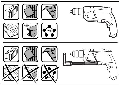
Intended Use
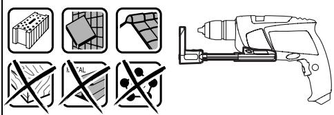
The machine is intended for impact drilling in brick, concrete and stone as well as for drilling in wood, metal and plastic. Machines with electronic control and right/left rotation are also suitable for screwdriving and thread-cutting.
Product Features
The numbering of the product features refers to the illustration of the machine on the graphics page.
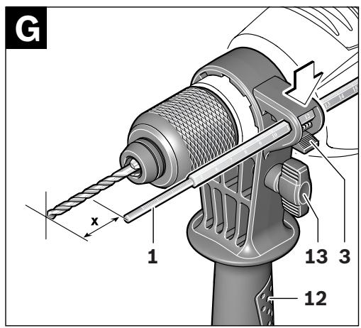
1 Depth stop
2 Keyless chuck
3 Button for depth stop adjustment
4 "Drilling/Impact Drilling" selector switch
5 Thumbwheel for electronic speed preselection (PSB 1000-2 RCE/PSB 1000-2 RCA)
6 Indicator for right rotation
7 Indicator for left rotation
8 Lock-on button for On/Off switch
9 Rotational direction switch
10 On/Off switch
11 Gear selector
12 Auxiliary handle
13 Wing bolt for adjustment of auxiliary handle
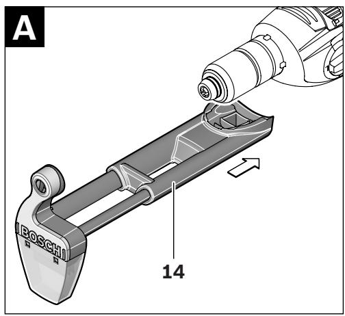
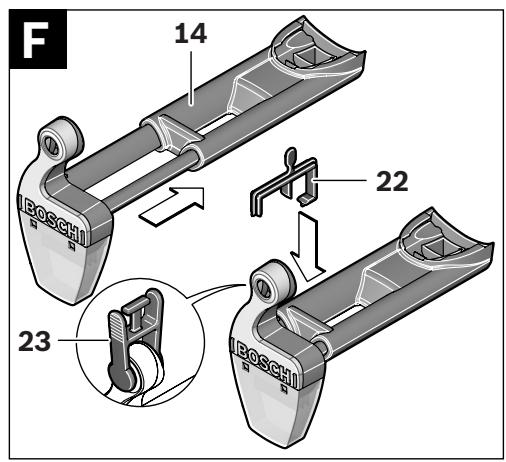
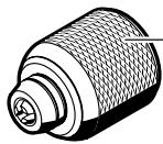
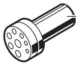
14 Extraction device with dust collector*
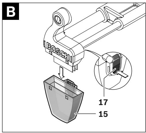
15 Dust collector*
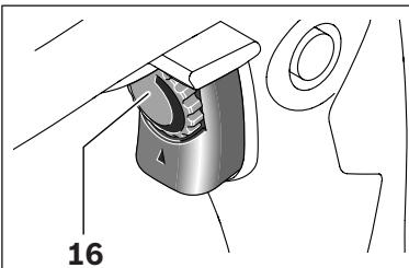
16 Thumbwheel for speed preselection (PSB 850-2 RE/PSB 850-2 RA)
17 Release button for dust collector*
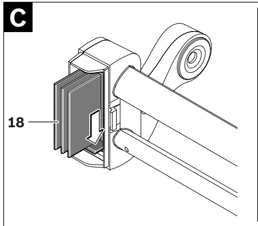
18 Filter element (micro filtersystem) *
19 Rubber gasket for dust collector*
20 Dust protection ring*
21 Release button for extraction device*
22 Clamp for extraction device*
23 Locking latch for dust collector*
24 Universal bit holder*
25 Screwdriver bit*
26 Allen key**
*Accessories shown or described are not part of the standard delivery scope of the product. A complete overview of accessories can be found in our accessories program.
**Commercially available (not included in the delivery scope)
20 | English
Technical Data
| Impact Drill | PSB ... | 850-2 RE | 850-2 RA | 1000-2 RCE | 1000-2 RCA |
| Article number | 3 603 ... | A73 0.. | A73 0.. | A73 5.. | A73 5.. |
| Rated power input | W | 850 | 850 | 1000 | 1000 |
| Output power | W | 420 | 420 | 530 | 530 |
| No-load speed | | | | | |
| - 1st gear | min^-1 | 50-850 | 50-850 | 50-1100 | 50-1100 |
| - 2nd gear | min^-1 | 50-2800 | 50-2800 | 50-2800 | 50-2800 |
| Rated speed | | | | | |
| - 1st gear | min^-1 | 850 | 850 | 1100 | 1100 |
| - 2nd gear | min^-1 | 2800 | 2800 | 2800 | 2800 |
| Impact rate | | | | | |
| - 1st gear | min^-1 | 14450 | 14450 | 18700 | 18700 |
| - 2nd gear | min^-1 | 47600 | 47600 | 47600 | 47600 |
| Rated torque | | | | | |
| - 1st gear | Nm | 4.6 | 4.6 | 3.5 | 3.5 |
| - 2nd gear | Nm | 1.3 | 1.3 | 1.0 | 1.0 |
| Torque at max. output power | | | | | |
| - 1st gear | Nm | 46 | 46 | 60 | 60 |
| - 2nd gear | Nm | 12 | 12 | 18 | 18 |
| Speed preselection | | ● | ● | ● | ● |
| Constant electronic control | | - | - | ● | ● |
| Right/left rotation | | ● | ● | ● | ● |
| Dust extraction | | - | ● | - | ● |
| Fully automatic spindle locking (Auto-lock) | | ● | ● | ● | ● |
| Spindle collar dia. | mm | 43 | 43 | 43 | 43 |
| Maximum drilling diameter (1st/2nd gear) | | | | | |
| - Brickwork | mm | 20/16 | 20/16 | 22/16 | 22/16 |
| - Concrete | mm | 18/13 | 18/13 | 20/13 | 20/13 |
| - Steel | mm | 13/8 | 13/8 | 16/8 | 16/8 |
| - Wood | mm | 40/25 | 40/25 | 40/25 | 40/25 |
| - with extraction device mounted | mm | 13/13 | 13/13 | 13/13 | 13/13 |
| Chuck clamping range | mm | 1.5-13 | 1.5-13 | 1.5-13 | 1.5-13 |
| Weight according to EPTA-Procedure 01/2003 | | | | | |
| - with extraction device | kg | - | 2.5 | - | 2.6 |
| - without extraction device | kg | 2.2 | - | 2.3 | - |
| Protection class | | □/II | □/II | □/II | □/II |
The values given are valid for nominal voltages [U] of 230/240 V. For lower voltage and models for specific countries, these values can vary.
Please observe the article number on the type plate of your machine. The trade names of the individual machines may vary.
Noise/Vibration Information
| | PSB 850-2 RE PSB 850-2 RA | PSB 1000-2 RCE PSB 1000-2 RCA |
| Measured values determined according to EN 60745. |
| Typically the A-weighted noise levels of the product are: |
| Sound pressure level | dB(A) | 97 | 100 |
| Sound power level | dB(A) | 108 | 111 |
| Uncertainty K= | dB | 3 | 3 |
| Wear hearing protection! |
| Vibration total values (triax vector sum) determined according to EN 60745: |
| Drilling into metal: |
| Vibration emission value ah | m/s2 | 6.0 | 6.0 |
| Uncertainty K= | m/s2 | 1.5 | 1.5 |
| Impact drilling into concrete: |
| Vibration emission value ah | m/s2 | 26 | 26 |
| Uncertainty K= | m/s2 | 2.5 | 2.5 |
| Screwdriving without impact: |
| Vibration emission value ah | m/s2 | <2.5 | <2.5 |
| Uncertainty K= | m/s2 | 1.5 | 1.5 |
| Tapping: |
| Vibration emission value ah | m/s2 | <2.5 | <2.5 |
| Uncertainty K= | m/s2 | 1.5 | 1.5 |
The vibration emission level given in this information sheet has been measured in accordance with a standardised test given in EN 60745 and may be used to compare one tool with another. It may be used for a preliminary assessment of exposure.
The declared vibration emission level represents the main applications of the tool. However if the tool is used for different applications, with different accessories or poorly maintained, the vibration emission may differ. This may significantly increase the exposure level over the total working period.
An estimation of the level of exposure to vibration should also take into account the times when the tool is switched off or when it is running but not actually doing the job. This may significantly reduce the exposure level over the total working period.
Identify additional safety measures to protect the operator from the effects of vibration such as: maintain the tool and the accessories, keep the hands warm, organisation of work patterns.
We declare under our sole responsibility that the product described under “Technical Data” is in conformity with the following standards or standardization documents: EN 60745 according to the provisions of the directives 2004/108/EC, 98/37/EC (until 28 Dec 2009), 2006/42/EC (from 29 Dec 2009).
Technical file at:
Robert Bosch GmbH, PT/ESC,
D-70745 Leinfelden-Echterdingen
Dr. Egbert Schneider
Senior Vice President
Engineering
Dr. Eckerhard Strötgen
Head of Product
Certification
ppa. Macaca i.v. Nuoyen
Robert Bosch GmbH, Power Tools Division
D-70745 Leinfelden-Echterdingen
25.05.2009
22 | English
Assembly
▶ Before any work on the machine itself, pull the mains plug.
(PSB 850-2 RA/PSB 1000-2 RCA)
Dusts from materials such as lead-containing coatings, some wood types, minerals and metal can be harmful to one's health. Touching or breathing-in the dusts can cause allergic reactions and/or lead to respiratory infections of the user or bystanders. Certain dusts, such as oak or beech dust, are considered as carcinogenic, especially in connection with wood-treatment additives (chromate, wood preservative). Materials containing asbestos may only be worked by specialists.
- Use dust extraction whenever possible.
- Provide for good ventilation of the working place.
- It is recommended to wear a P2 filter-class respirator.
Observe the relevant regulations in your country for the materials to be worked.
▶ Use the dust/chip extraction only when working concrete, brick and brickwork.
Wood or plastic chips can easily lead to clogging.
▶ WARNING Fire hazard! Do not work metallic materials with the extraction device
mounted. Hot metal chips can ignite parts of the extraction device.
To achieve optimum extraction results, please observe the following notes:
- Pay attention that the extraction device faces flush against the workpiece or the wall. This also makes drilling at a right angle easier.
- When using the extraction device, always work with the maximum speed.
- After reaching the desired drilling depth, pull the drill bit out of the drill hole first and then switch off the impact drill.
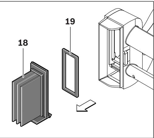
- Use the extraction device only with the filter element 18 mounted, as otherwise dust/chips could access the interior of the power tool and cause damage.
- Check the condition of the filter element 18 regularly. Replace a damaged filter element immediately.
- The dust protection ring 20 can wear, especially when working with large drill-bit diameters. Replace the dust protection ring when worn/damaged.
Guide the extraction device 14 from the front toward the bottom side of the impact drill. Pay attention that the extraction device 14 faces flush against the casing and that it is locked.
The dust collector 15 is sufficient for approx. 20 drillings with a drilling diameter of 10 mm.
When the extraction force diminishes the dust collector 15 must be emptied. For this, press on the riffled surface of the release button 17 and take off the dust collector 15.
Empty and clean the dust collector 15. Clean the filter element 18 by gently striking or tapping against it.
Check the filter element 18 for damage and replace it as required.
Press on the holder of the filter element 18 and pull it out. Replace the filter element 18 including the holder. When placing on the holder again, make sure that the rubber gasket 19 is inserted.
Reattach the dust collector 15 again and lock it by pressing against the smooth surface of the release button 17.


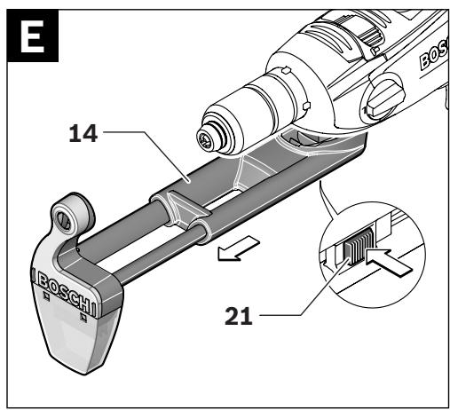
For disassembly of the extraction device 14, press release button 21 and pull off the extraction device 14 toward the front.
For stowing the extraction device 14 in the case, remove the extraction device 14, slide it together and attach clamp 22.
Attach the locking latch 23 or empty the dust collector 15 before placing down the extraction device.
Auxiliary Handle
▶ Operate your machine only with the auxiliary handle 12.
The auxiliary handle 12 can be set in 8 positions to achieve a safe and low-fatigue working stance.
Turn the wing bolt for adjustment of the auxiliary handle 13 in anticlockwise direction and push the auxiliary handle 12 forward until you can pivot it to the desired position. Then pull the auxiliary handle 12 back again and tighten the wing bolt 13 again in clockwise direction.
The required drilling depth X can be set with the depth stop 1.
Press the button for the depth stop adjustment 3 and insert the depth stop into the auxiliary handle 12.
The knurled surface of the depth stop 1 must face downward.
Pull out the depth stop until the distance between the tip of the drill bit and the tip of the depth stop correspond with the desired drilling depth X.
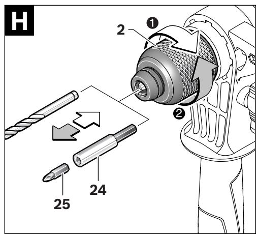
Keyless Chuck
The drill spindle is locked when the On/Off switch 10 is not pressed. This makes quick, convenient and easy changing of the tool in the drill chuck possible.
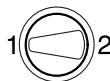
Open the keyless chuck 2 by turning in rotation direction ①, until the tool can be inserted. Insert the tool.
Firmly tighten the collar of the keyless chuck 2 by hand in rotation direction ② until the locking action (“click”) is no longer heard. This automatically locks the chuck.
The locking is released again to remove the tool when the collar is turned in the opposite direction.
When working with screwdriver bits 25, a universal bit holder 24 should always be used. Use only screwdriver bits that fit the screw head.
For driving screws, always position the “Drilling/Impact Drilling” selector switch 4 to the “Drilling” symbol.
Replacing the Drill Chuck
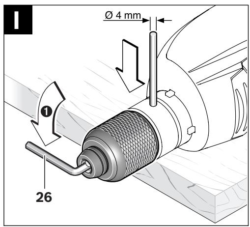
▶ Before any work on the machine itself, pull the mains plug.
Disassemble the auxiliary handle and set the gear selector 11 to the centre position between the 1st and 2nd gear.
Insert a steel pin with a diameter of ∅ 4 mm and approx. 50 mm of length into the drill hole on the spindle neck in order to lock the drill spindle.
Clamp the short end of an Allen key 26 into the keyless chuck 2.
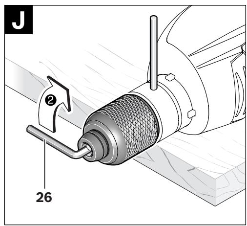
Place the machine on a stable surface (e. g. a workbench). Hold the machine firmly and loosen the keyless chuck 2 by turning the Allen key 26 in rotation direction ①. Loosen a tight-seated keyless chuck by giving the long end of the Allen key 26 a light blow. Remove the Allen key from the keyless chuck and completely unscrew the keyless chuck.


24 | English
The keyless chuck is mounted in reverse order.
▶ Remove the steel pin from the drill hole on the spindle neck after mounting is completed.

The drill chuck must be tightened with a tightening torque of approx. 50–55 Nm.
Operation
Starting Operation
▶ Observe correct mains voltage! The voltage of the power source must agree with the voltage specified on the nameplate of the machine. Power tools marked with 230 V can also be operated with 220 V.
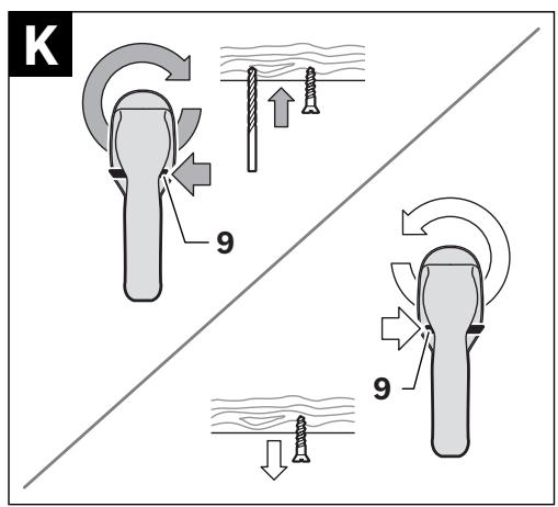
The rotational direction switch 9 is used to reverse the rotational direction of the machine. However, this is not possible with the On/Off switch 10 actuated.
Right Rotation: For drilling and driving in screws, push the rotational direction switch 9 left to the stop.
The indicator for right-hand rotation 6 indicates the selected rotational direction.
Left Rotation: For loosening and unscrewing screws and nuts, press the rotational direction switch 9 through to the right stop.
The indicator for left-hand rotation 7 indicates the selected rotational direction.
Setting the Operating Mode

Drilling and Screwdriving
Set the selector switch 4 to the “Drilling” symbol.

Impact Drilling
Set the selector switch 4 to the “Impact drilling” symbol.
The selector switch 4 engages noticeably and can also be actuated with the machine running.
Gear Selection, Mechanical
The gear selector 11 can be actuated on machines running at low speed. However, this should not be done when the machine is stopped, at full load or running at maximum speed.
Two speed ranges can be preselected with the gear selector 11.
Gear I:
Low speed range; for working with large drilling diameter or for driving in screws.

Gear II:
High speed range; for working with small drilling diameter.
If the gear selector 11 cannot be fully engaged, lightly rotate the drive spindle with the drill bit by twisting the drill chuck.
Switching On and Off
To start the machine, press the On/Off switch 10 and keep it pressed.
To lock the pressed On/Off switch 10, press the lock-on button 8.
To switch off the machine, release the On/Off switch 10 or when it is locked with the lock-on button 8, briefly press the On/Off switch 10 and then release it.
Adjusting the Speed/Impact Frequency
The speed/impact rate of the switched on power tool can be variably adjusted, depending on how far the On/Off switch 10 is pressed.
Light pressure on the On/Off switch 10 results in low speed/impact rate. Further pressure on the switch increases the speed/impact rate.
Preselecting the Speed/Impact Frequency (PSB 850-2 RE/PSB 850-2 RA)
With the thumbwheel for speed preselection 16, the required speed/impact frequency can be preselected even during operation.
The required speed/impact frequency depends on the material and the working conditions, and can be determined through practical testing.


Electronic Speed Preselection (PSB 1000-2 RCE/PSB 1000-2 RCA)
With the thumbwheel for electronic speed preselection 5, the required speed/impact frequency can be selected even if the machine is running.
The required speed/impact frequency depends on the material and the working conditions, and can be determined through practical testing.
For working with low speed.
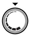
For working with maximum speed.

Working Advice
▶ Apply the power tool to the screw/nut only when it is switched off. Rotating tool inserts can slip off.
After longer periods of working at low speed, allow the machine to cool down by running it for approx. 3 minutes at maximum speed with no load.
Maintenance and Service
Maintenance and Cleaning
▶ Before any work on the machine itself, pull the mains plug.
▶ For safe and proper working, always keep the machine and ventilation slots clean.
If the machine should fail despite the care taken in manufacturing and testing procedures, repair should be carried out by an after-sales service centre for Bosch power tools.
In all correspondence and spare parts order, please always include the 10-digit article number given on the type plate of the machine.
After-sales Service and Customer Assistance
Our after-sales service responds to your questions concerning maintenance and repair of your product as well as spare parts. Exploded views and information on spare parts can also be found under:
Our customer service representatives can answer your questions concerning possible applications and adjustment of products and accessories.
Great Britain
Robert Bosch Ltd. (B.S.C.)
P.O. Box 98
Broadwater Park
North Orbital Road
Denham
Uxbridge
UB 9 5HJ
Tel. Service: +44 (0844) 736 0109
Fax: +44 (0844) 736 0146
Australia, New Zealand and Pacific Islands
Robert Bosch Australia Pty. Ltd.
Power Tools
Locked Bag 66
Clayton South VIC 3169
Customer Contact Center
Inside Australia:
Phone: +61 (01300) 307 044
Fax: +61 (01300) 307 045
Inside New Zealand:
Phone: +64 (0800) 543 353
Fax: +64 (0800) 428 570
Outside AU and NZ:
Phone: +61 (03) 9541 5555
www.bosch.com.au
26 | English
Republic of South Africa
Customer service
Hotline: +27 (011) 6 51 96 00
Gauteng - BSC Service Centre
35 Roper Street, New Centre
Johannesburg
Tel.: +27 (011) 4 93 93 75
Fax: +27 (011) 4 93 01 26
E-Mail: bsctools@icon.co.za
KZN - BSC Service Centre
Unit E, Almar Centre
143 Crompton Street
Pinetown
Tel.: +27 (031) 7 01 21 20
Fax: +27 (031) 7 01 24 46
E-Mail: bsc.dur@za.bosch.com
Western Cape - BSC Service Centre
Democracy Way, Prosperity Park
Milnerton
Tel.: +27 (021) 5 51 25 77
Fax: +27 (021) 5 51 32 23
E-Mail: bsc@zsd.co.za
Bosch Headquarters
Midrand, Gauteng
Tel.: +27 (011) 6 51 96 00
Fax: +27 (011) 6 51 98 80
E-Mail: rbsa-hq.pts@za.bosch.com
Disposal
The machine, accessories and packaging should be sorted for environmental-friendly recycling.
Only for EC countries:
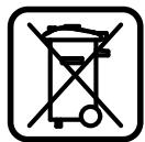
Do not dispose of power tools into household waste!
According to the European Guideline 2002/96/EC for Waste Electrical and Electronic Equipment and its implementation into national
right, power tools that are no longer usable must be collected separately and disposed of in an environmentally correct manner.
Subject to change without notice.
Dr. Egbert Schneider
Senior Vice President
Engineering
Dr. Eckerhard Strötgen
Head of Product
Certification

Robert Bosch GmbH, Power Tools Division D-70745 Leinfelden-Echterdingen 25.05.2009
Montage
Robert Bosch (France) S.A.S.
Dr. Egbert Schneider
Senior Vice President
Engineering
Dr. Eckerhard Strötgen
Head of Product
Certification

Robert Bosch GmbH, Power Tools Division D-70745 Leinfelden-Echterdingen 25.05.2009
Montaje
Dr. Egbert Schneider
Senior Vice President
Engineering
Dr. Eckerhard Strötgen
Head of Product
Certification

Robert Bosch GmbH, Power Tools Division D-70745 Leinfelden-Echterdingen 25.05.2009
Montagem
- Antes de todos trabalhos na ferramenta eléctrica deverá puxar a ficha de rede da tomada.
Dr. Egbert Schneider
Senior Vice President
Engineering
Dr. Eckerhard Strötgen
Head of Product
Certification

Robert Bosch GmbH, Power Tools Division D-70745 Leinfelden-Echterdingen 25.05.2009
Montaggio
Dr. Egbert Schneider
Senior Vice President
Engineering
Dr. Eckerhard Strötgen
Head of Product
Certification

Robert Bosch GmbH, Power Tools Division D-70745 Leinfelden-Echterdingen 25.05.2009
Montage
Senior Vice President
Engineering
Dr. Eckerhard Strötgen
Head of Product
Certification
ppu. Macena i.v. Nuoyen
Robert Bosch GmbH, Power Tools Division
D-70745 Leinfelden-Echterdingen
25.05.2009
Montering
Bosch Service Center
Telegrafvej 3
2750 Ballerup
Tel. Service Center: +45 (4489) 8855
Fax: +45 (4489) 87 55
E-Mail: vaerktoej@dk.bosch.com
Bortskaffelse
Dr. Egbert Schneider
Senior Vice President
Engineering
Dr. Eckerhard Strötgen
Head of Product
Certification

i.v. Mogen
Robert Bosch GmbH, Power Tools Division D-70745 Leinfelden-Echterdingen 25.05.2009


96 | Svenska
Montage
Bosch Service Center
Telegrafvej 3
2750 Ballerup
Danmark
Tel.: +46 (020) 41 44 55
Fax: +46 (011) 18 76 91
Avfallshantering
Senior Vice President
Engineering
Dr. Eckerhard Strötgen
Head of Product
Certification
ppu. Macena i.v. Nuoyen
Robert Bosch GmbH, Power Tools Division
D-70745 Leinfelden-Echterdingen
25.05.2009
Norsk | 105
Montering
Senior Vice President
Engineering
Dr. Eckerhard Strötgen
Head of Product
Certification

i.v. Mogen
Robert Bosch GmbH, Power Tools Division
D-70745 Leinfelden-Echterdingen
25.05.2009
114 | Suomi
Asennus
Dr. Egbert Schneider Dr. Eckerhard Strötgen
Senior Vice President Head of Product
Engineering Certification

Robert Bosch GmbH, Power Tools Division
D-70745 Leinfelden-Echterdingen
25.05.2009
Συναρμολόγηση
Dr. Egbert Schneider
Senior Vice President
Engineering
Dr. Eckerhard Strötgen
Head of Product
Certification


Robert Bosch GmbH, Power Tools Division D-70745 Leinfelden-Echterdingen 25.05.2009


134 | Türkçe
Montaj
Bosch San. ve Tic. A.S.
Ahi Evran Cad. No:1 Kat:22
Polaris Plaza
80670 Maslak/Istanbul
natural_image
Technical line drawing of a mechanical device with a cylindrical shaft and housing (no text or symbols)
2 609 255 728
2 603 001 019

2 600 206 005
2 609 255 730
2 607 990 050
(S 41)
natural_image
Technical line drawing of a mechanical press or clamp device with no visible text or symbols
2 608 180 009
(DP 500)
2 608 030 053
(MS 65)
2 608 030 055
(MS 80)