
BH-40TEI GW - Oven Vivax - Free user manual and instructions
Find the device manual for free BH-40TEI GW Vivax in PDF.


| Product Type | Built-in Electric Oven |
| Brand | Vivax |
| Model | BH-40TEI GW |
| Dimensions (H x W x D) | 595 x 595 x 575 mm |
| Oven Capacity | 65 liters |
| Energy Source | Electric |
| Energy Efficiency Class | A |
| Temperature Range | 50°C - 250°C |
| Number of Cooking Functions | 8 |
| Cleaning System | Hydrolysis Cleaning |
| Door Type | Cool Touch, Stainless Steel |
| Interior Light | Yes |
| Display | LED Touch |
| Timer | Digital with Delay Start |
| Safety Features | Child Lock, Automatic Shut-off |
| Net Weight | 32 kg |
| Power Consumption | 2.5 kW |
| Voltage / Frequency | 220-240 V / 50 Hz |
| Accessories Included | Grid, Baking Tray, Rotisserie Kit |
| Warranty | 2 Years |
Frequently Asked Questions - BH-40TEI GW Vivax
User questions about BH-40TEI GW Vivax
0 question about this device. Answer the ones you know or ask your own.
Ask a new question about this device
Download the instructions for your Oven in PDF format for free! Find your manual BH-40TEI GW - Vivax and take your electronic device back in hand. On this page are published all the documents necessary for the use of your device. BH-40TEI GW by Vivax.
USER MANUAL BH-40TEI GW Vivax
natural_image
Four-panel kitchen gas stove with four circular vented lights and a red indicator light (no text or symbols visible)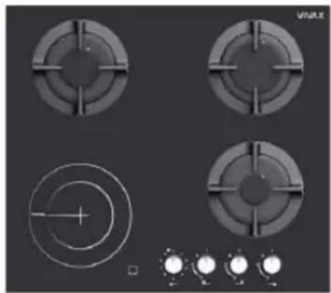
natural_image
Four circular mechanical components with cross-sectional views and a set of three labeled controls (no text or symbols visible)
natural_image
Four identical gas stove fans arranged in a 2x2 grid on a dark background, with no visible text or symbols.
natural_image
Four black circular gas stove covers arranged in a 2x2 grid, with a row of circular indicators below (no text or symbols on covers)UPOZORENJE:
natural_image
Warning symbol with exclamation mark inside a triangle (no text or numbers)SIGURNOSNA UPOZORENJA
- Ove uputa je važeća samo ako je uređaj označen oznakom zemlje za koju je uređaj namijenjen. Ako oznaka zemlje u kojoj se uređaj ugrađuje nedostaje, potrebno je pogledati tehničke upute koje sadržavaju potrebne upute za prilagodbu uređaja za određenu zemlju ugradnje.
- Nemojte koristiti abrazivna sredstva ili oštre metalne nožiće ili slično za čišćenje, jer na taj način možete nepovratno oštetiti površinu.
natural_image
Diagram of a greenhouse with a stove, air pollutants, and cooling system (no text or labels)
natural_image
Diagram of a house interior with steam rising from a stove, showing airflow and ventilation (no text or symbols)natural_image
Diagram showing a window mounted on a vertical post with an inset magnified view of the structural detail (no text or symbols)
natural_image
Simple line drawing of a room with a window, door, and stove (no text or symbols)| Veličina prostorije Otvor za ventilaciju | |
| Manje od 5m3 Min. 100 cm | 2 |
| 5m3-10m3 Min. 50 cm | 2 |
| Veće od 10m3 Nije potrebno | |
| Podrum Min. 65 cm | 2 |
paljenje i pričekajte najmanje jednu minutu prije nego što pokušate ponovno upaliti plamenik.
-
Za pravilan rad, napu, plinsku cijev i stezaljku treba povr emeno mijenjati u skladu s preporukama proizvođača i kada je to potrebno.
-
Plin treba ispravno i dobro sagorjevati. Ispravno sagorijevanje se prepoznaje tao da je plamen stalan i plavkaste boje. Ako plin n e sagorjeva ispravno, može nastati ugljični monoksid (CO). Ugljični monoksid je bezbojan plin bez mirisa i vrlo otrovan; čak i male količine imaju smrtonosni učinak.
-
Saznajte od svojeg lokalne dobavljača plina telefonske brojeve za hitne intervencije u vezi s plinom i mjerama koje treba poduzet i ako se otkrije miris plina.
natural_image
Pure technical diagram showing a rectangular block with two labeled points A and B, no text or symbols present.| A B | |
| 50mm min 50 | mm min |

natural_image
Diagram of a mechanical component with a rotating wheel and textured surface (no text or symbols)Traka za brtvljenje.

natural_image
Technical line drawings of mechanical components and structural elements (no text or symbols)Upozorenja
natural_image
Simple line drawing of a mechanical component with a cross mark, no text or symbols present
natural_image
Diagram of a mechanical device with a circular component and lever mechanism (no text or symbols)natural_image
Pure diagram of a cooking pot with crossed arrows indicating pressure or flow direction (no text or symbols)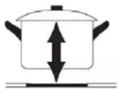
natural_image
Simple line drawing of a cooking pot with upward and downward arrows indicating direction (no text or symbols)- Postavite krunu plamenika (4) na čašu plamenika (5) tako da se uređaj za paljenje i uređaj za nadzor plamena poklapa s odgovarajućim rupama na kruni plamenika. Kruna plamenika mora pravilno sjesti na svoje mjesto.
- Postavite pokrov plamenika (1,2,3) na krunu plamenika (4) tako da se pričvrsna izbočenja poklapaju sa odgovarajućim udubljenjima.

natural_image
Four-panel kitchen appliance with circular and square top fixtures, no visible text or symbols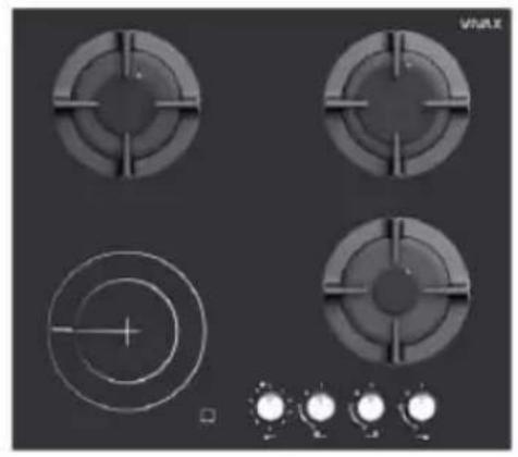
natural_image
Four circular industrial gauges with cross-shaped cutouts and a central dial indicator, shown above with three small circular lights (no text or symbols on the gauges themselves)
natural_image
Four identical electric stove fans arranged in a 2x2 grid on a dark background, with no visible text or symbols.
natural_image
Four black circular gas stove covers arranged in a 2x2 grid, with no visible text or symbols on the covers or background.UPOZORENJE: ODRŽAVANJE STAKLOKERAMIČKE PLOČE
Proliveni šećer, sos, voćni sok, itd. treba čim pre obrisati mekom krpom namočenom u toploj vodi sa deterdžentom ili sa specijalnim sredstvom za održavanje staklokeramičkih ploča.
Nemojte dopustiti da se šećer, sosevi ili sokovi zapeku na ploči. To može NEPOVRATNO da oštetiti staklokeramičku ploču, čak može prouzrokovati otapanje staklene površine ili otežati kasnije čišćenje!
natural_image
Warning symbol with exclamation mark inside a triangle (no text or numbers)SIGURNOSNA UPOZORENJA
- Ovo uputstvo važi samo ako je uređaj označen oznakom zemlje za koju je uređaj namenjen. Ukoliko nedostaje oznaka zemlje, potrebno je pogledati tehničko uputstvo koje sadrži neophodne informacije za prilagođavanje uređaja određenoj zemlji u kojoj se instalira.
- Koristite ovaj uređaj samo u skladu sa ovim uputstvima.
natural_image
Diagram of a greenhouse with a stove inside, showing airflow and heat transfer (no text or labels)
natural_image
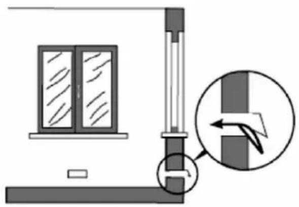
Diagram of a house interior with steam rising from a stove, showing airflow and heat transfer (no text or symbols)Stalno i dugotrajno korišćenje uređaja može zahtevati izvođenje dodatne ventilacije, naprimer otvaranje prozora ili povećanje efikasnosti mehaničke ventilacije (povećanje brzine protoka vazduha ventilacije, ako je moguće).
natural_image
Diagram showing a window mounted on a beam with an inset close-up of a mechanical component (no text or symbols)
natural_image
Simple line drawing of a room with a window, door, lamp, and coffee cup (no text or symbols)| Veličina prostorije Otvor za ventilaciju | |
| Manje od 5m3 Min. 100 cm | 2 |
| 5m3-10m3 Min. 50 cm | 2 |
| Veće od 10m3 Nije potrebno | |
| Podrum Min. 65 cm | 2 |
zaustavite paljenje i sačekajte najmanje jedan minut pre nego što pokušate da ponovo upalite gorionik.
-
Za pravilan rad, aspirator, gasnu cev i stezaljku treba periodično menjati u skladu sa preporukama proizvođača i kada je to potrebno.
-
Gas treba da gori pravilno i dobro. Pravilno sagorevanje se prepoznaje po tome što je plamen konstantan i plavičaste b oje. Ako gas ne gori kako treba, može da se formira ugljen monoksid (CO). Ugljenmonoksid je bezbojan gas bez mirisa i veoma toksičan; čak i male količine imaju smrtonosni efekat.
-
Od svog lokalnog snabdevača gasom saznajte brojeve telefon a za hitne intervencije u vezi sa gasom i radnje koje treba predzeti ako se otkrije miris gasa.
natural_image
Pure technical diagram showing a rectangular block with labeled dimensions A and B, intersected by diagonal lines (no text or symbols beyond labels)| A B | |
| 50mm min 50 | mm min |

natural_image
Diagram of a layered structure with a spiral component attached, showing no text or symbols.Traka za dihtanje
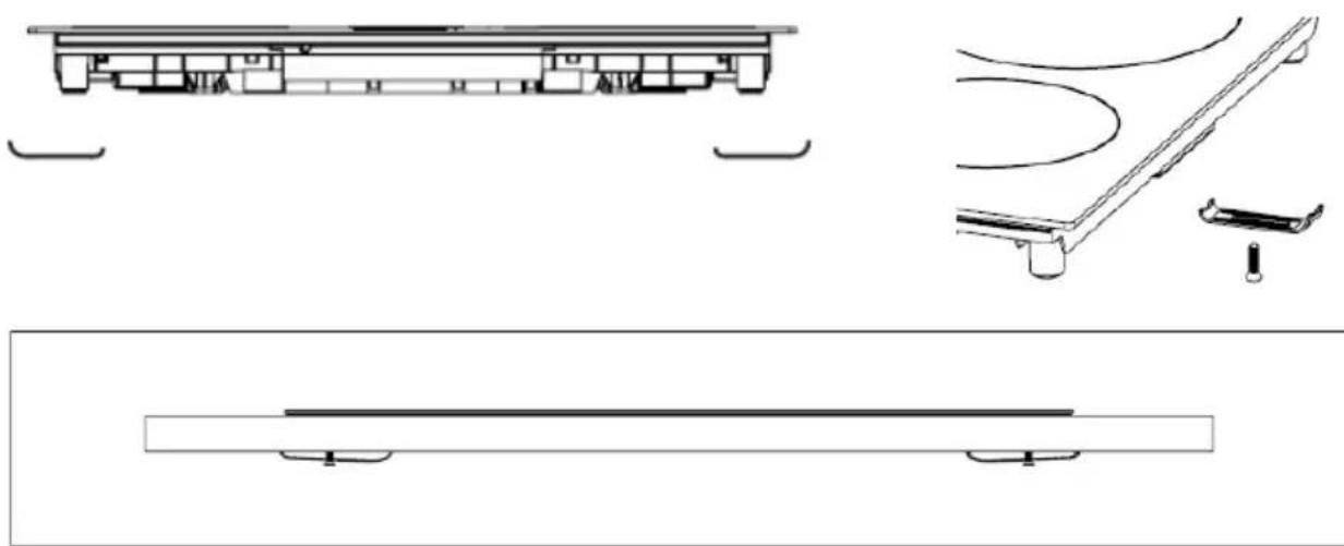
- Pričvrstite ploču na radnu ploču pomoću nosača isporučenih u pri boru, kao što je prikazano na donjoj slici.

Upozorenja
- Ploču za kuvanje mora instalirati kvalifikovana servisna osoba ili tehničar. Preporuka je da u slučaju da nemate dovoljno iskustva za instalaciju, kontaktirate ovlašćeni servis ili drugu stručnu osobu za ugradnju ploče.
- Ploča za kuvanje ne sme se montirati iznad rashladnog uređaja, mašine za pranje posuđa ili sušilice.
- Ploča za kuvanje mora biti postavljena tako da se može osigurati odvođenje toplote, čime se osigurava optimalan rad i duži radni vek uređaja.
- Zidovi, vertikalne stranice ormarića i površine iznad radne ploče moraju biti otporne na toplotu.
- Kako bi se izbegla oštećenja, radna ploča i zaptivke moraju biti otporni na toplotu.
- Za čišćenje ploče ne sme se koristiti parni čistač.
- Ova ploča za kuvanje sme se spojiti na električni priključak koji ima impendansu sistema koja nije veća od 0,427 ohma. Ako je potrebno, kontaktirajte vašeg distributera električne energije ili ovlašćenog električara za informacije o impedansi sistema.
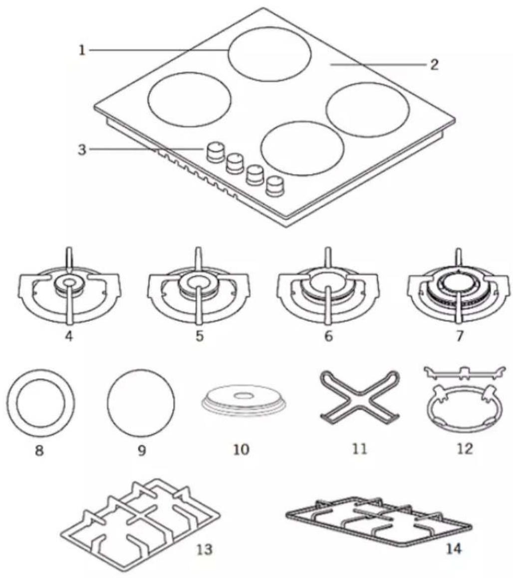
Glavni delovi
-
Položaj gorionika / Grejne površine
-
Dvozonski keramički grejač (120 mm / 180 mm) *
-
Staklena ili metalna površina
-
Keramički grejač / Grejna ploča (180 ili 140 mm) *
-
Kontrolna dugmad
-
Grejaća ploča 145 ili 180 mm *
-
Mali gorionik
-
Adapter za malu posudu *
-
Srednji gorionik
-
Wok adapter za gorionik *
-
Veliki gorionik
-
Nosač posuda od kovanog željeza *
-
Wok gorionik
-
Nosač posuda - Emajlirani *
* Opcija, ne primenjuje se na sve modele. Gornje slike služe samo u svrhu ilustracije. Proverite stvarno stanje na vašem uređaju.
Upotreba uređaja
Na upravljačkoj ploči, uz okretne gumbe biti će prikazani sledeći simboli:
Crna tačka: Isključeno
Veliki plamen: maksimalna jačina
Mali plamen: minimalna jačina
Model: 4 gorionika:

flowchart
graph TD
    A["Step 1"] --> B["Circle Node"]
    C["Step 2"] --> D["Circle Node"]
    E["Step 3"] --> F["Circle Node"]
    G["Step 4"] --> H["Circle Node"]
- Prednji levi gorionik
- Zadnji levi gorionik
- zadnji desni gorionik
- Prednji desni gorionik
Model: 3 gorionika + 1 keramički grejač / grejna ploča
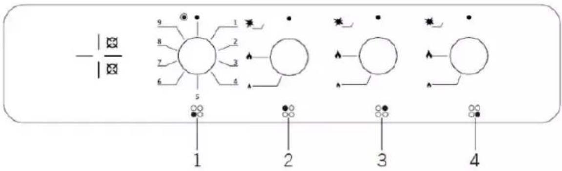
- Prednji levi Keramički grejač / Grejna ploča
- Zadnji levi gorionik
- Zadnji desni gorionik
- Prednji desni gorionik
Napomena: Gore navedene upravljačke ploče služe samo u svrhu ilustracije. Proverite stvarno stanje na vašem uređaju
Pre upotrebe ploče za kuvanje, uverite se da su gorionici u ispravnom položaju. Pravilna ugradnja gorionika je prikazana na slici.

natural_image
Simple line drawing of a mechanical component with a cross mark, no text or symbols present
natural_image
Diagram of a mechanical device with a circular component and lever mechanism (no text or symbols)Imajte na umu da su krune i drugi delovi gorionika pravilno postavljeni na ploču za kuvanje. Ako gorionik se ne pali, proverite položaj gorionika. Ako je gorionik nepravilno instaliran, može doći do nepotpunog sagorevanja i curenja gasa tokom rada gorionika.
- Minimalna jačina plamena je u krajnjem položaju dugmeta okrenutog suprotno od kazaljke na satu.
- Jačina plamena se može podešavati između maksimalnog i minimalnog položaja.
- Simbol na upravljačkoj ploči, pored upravljačkog dugmeta, označava koji gorionik radi.
- Uređaj je opremljen elktričnim sistemom za paljenje. Jednostavno pritisnite i okrenite dugme u smeru suprotnom od kazaljke na satu do simbola maksimalnog plamena dok se plamen ne pojavi. Ako se gorionik ne upali u prvih 15 sekundi, vratite dugme u isključeni položaj (●) i ne pokušavajte ga ponovno pokrenuti 60 sekundi.
natural_image
Simple line drawing of a cooking pot with crossed arrows indicating pressure or heat (no text or symbols)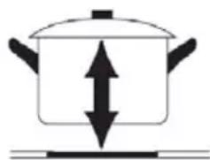
natural_image
Simple line drawing of a pot with an upward and downward arrow indicating pressure or direction (no text or symbols)- Ne stavljajte više ulja u posudu od jedne trećine njene zapremine. Ne ostavljajte ulje koje se zagreva bez nadzora. Ekstremno vruća ulja mogu izazvati požar.
- Koristite samo posuđe i tiganje sa tretiranom podlogom. Oštre ivice uzrokuju ogrebotine na površini ploče.
- Ne koristite aluminijumske posude i tiganje na staklenoj površini. Aluminijum može oštetiti površinu ploče za kuvanje.
Veličine posuda
Preporučeni prečnik posuda navedeni su u donjoj tabeli.
| Gorionik/Grejna zona | Prečnik posude Staklena ploča | Prečnik posude metalna ploča |
| Mali gorionik 12-18 | cm 12-18 cm | |
| Srednji gorionik 18 | -20 cm 18-22 cm | |
| Veliki gorionik 22-24 | cm 22-26 cm | |
| Wok gorionik 24-26 | cm 26-32 cm |
UPOZORENJE: Posuda za kuvanje treba da ima minimalni prečnik od 120 mm
IZBOR ISPRAVNOG POSUĐA

LOŠE LOŠE LOŠE ISPRAVNO

LOŠE LOŠE LOŠE ISPRAVNO
- Nemojte koristiti posuđe s nazubljenim, neravnim rubovima ili zakrivljenim dnom.
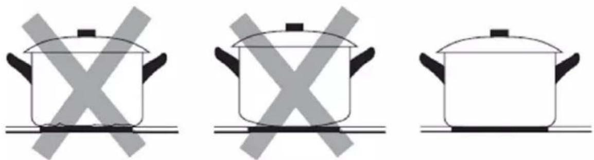
- Osigurajte da je dno posude glatko, da leži ravno uz staklo i da je iste veličine kao i zona za kuvanje. Posudu uvijek postavite u sredinu zone za kuvanje.

UPUTSTVO ZA KUVANJE

Pripazite prilikom prženja jer se ulje i masnoća vrlo brzo zagrejavaju, posebno ako koristite najvišu snagu grejanja. Na ekstremno visokim temperaturama ulje i masnoća će se spontano zapaliti, što predstavlja ozbiljnu opasnost od požara.
- Postavite krunu gorionika (4) na čašu gorionika (5) tako da se uređaj za paljenje i uređaj za nadzor plamena poklapa sa odgovarajućim rupama na kruni gorionika. Kruna gorionika mora pravilno sesti na svoje mesto.
- Postavite poklopac gorionika (1,2,3) na krunu gorionika (4) tako da se pričvrsna izbočenja poklapaju sa odgovarajućim udubljenjima.

natural_image
Four-panel kitchen gas stove with four circular vented lights and a red indicator light (no text or symbols visible)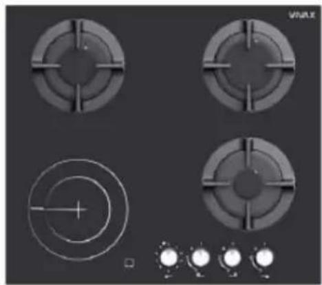
natural_image
Four circular industrial gauges with cross-shaped cutouts and a central spiral pattern, displayed on a dark surface with control knobs below (no text or symbols visible)
natural_image
Four identical gas stove fans arranged in a 2x2 grid on a dark background, with no visible text or symbols.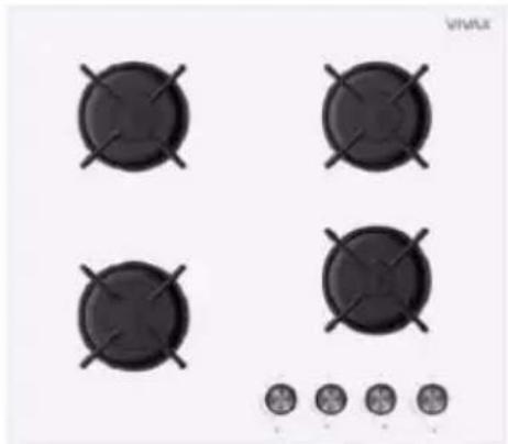
natural_image
Four black circular gas stove covers arranged in a 2x2 grid, with no visible text or symbols.ПРЕДУПРЕДУВАЊЕ:
natural_image
Warning symbol with exclamation mark inside a triangle (no text or numbers)natural_image
Diagram showing a window mounted on a vertical post with an inset magnified view of the structural detail (no text or symbols)
natural_image
Simple line drawing of a room with a window, door, and lamp (no text or symbols)| A (mm) B | (mm) C (mm) | D E | ||
| 760 50 mini 30mini Ulaz | zraka | Izlaz | zraka 10 mm |
natural_image
Diagram of a mechanical component with a roller and mounting base (no text or symbols)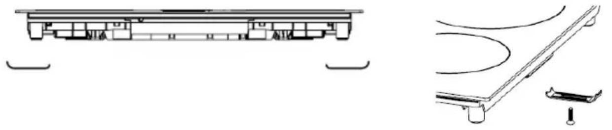
natural_image
Technical line drawings of a mechanical assembly and support structure (no text or symbols)
natural_image
Simple line drawing of a rectangular beam with two supports at both ends (no text or symbols)Предупредување
natural_image
Simple line drawing of a kitchen sink with a circular component and a cross symbol (no text or labels)
natural_image
Diagram of a mechanical or electrical component with concentric rings and a downward arrow indicator (no text or symbols)natural_image
Pure diagram of a cooking pot with crossed arrows indicating direction, no text or symbols present
natural_image
Simple line drawing of a cooking pot with upward and downward arrows indicating direction (no text or symbols)natural_image
Simple black-and-white icon of a cooking pot with steam rising and a cross mark on the side (no text or symbols)ЛОШО

ЛОШО
ЛОШО

ПРАВИЛНО

natural_image
Pure electrical circuit lines without any symbolsЛОШО

ЛОШО

natural_image
Symbolic black-and-white image of a traditional Chinese roof with crossed beams (no text or symbols)ПРАВИЛНО
natural_image
Simple black-and-white illustration of a cooking pot (no text or symbols)natural_image
Simple line drawing of a cooking pot with crossed-out X symbol (no text or labels)
natural_image
Simple line drawing of a cooking pot with crossed X marks, no text or symbols present
natural_image
Simple line drawing of a cooking pot on a stove (no text or symbols)natural_image
Simple line drawing of a cooking pot with crossed X marks (no text or symbols)
natural_image
Simple line drawing of a cooking pot with X-shaped marks (no text or symbols)
natural_image
Simple line drawing of a cooking pot with crossed-out X symbol (no text or labels)
natural_image
Simple line drawing of a cooking pot on a stove (no text or symbols)УПАТСТВО ЗА ГОТВЕЊЕ

natural_image
Four-panel kitchen gas stove with four circular vented lights and a red indicator light (no text or symbols visible)
natural_image
Four circular industrial gauges with cross-shaped cutouts and a central spiral pattern, displayed on a dark surface with control knobs below (no text or symbols visible)
natural_image
Four identical gas stove fans arranged in a 2x2 grid on a dark background, with no visible text or symbols.
natural_image
Four black circular gas stove covers arranged in a 2x2 grid, with no visible text or symbols on the covers or background.PARALAJMËRIM:
MIRËMBAJTJA E PJESËS/ PLLAKËS SË SIPËRME TË SHPORETIT VITROQERAMIKË
natural_image
Warning symbol with exclamation mark inside a triangle (no text or numbers)PARALAJMËRIME TË RËNDËSISHME
natural_image
Technical line drawing of a U-shaped mechanical component with internal channels (no text or symbols)kapaku/ bracket x4
Sealing Sponge x4

Vida x4

NG Injektori
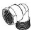
NG Tubi i gazit
Lidhja x 1
Manuali udhzimev x 1
INSTALIMI I SHPORETIT TUAJ
LIDHJA ELEKTRIKE
natural_image
Diagram of a greenhouse with a stove, air conditioning unit, and cooling system (no text or labels)
natural_image
Diagram of a house interior with steam rising from a stove, showing airflow and heat transfer (no text or symbols)natural_image
Diagram showing a window and vertical structure with an arrow indicating direction, no text or symbols present
natural_image
Simple line drawing of a room with a window, door, lamp, and steaming cup (no text or symbols)Lidhjet LPG/ Connection

Lidhjet NG/ Connection
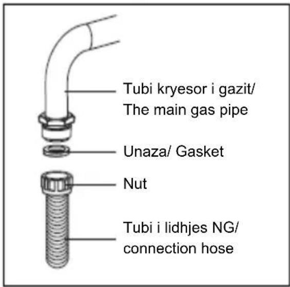
Rregullimi i gazit

Shtypja/ Tap Unaza rrotulluese/Seali ng ring

Vida rregulluese/Adjustment screw
natural_image
Pure technical diagram showing a rectangular block with two labeled points A and B, intersected by diagonal lines (no text or symbols beyond labels)natural_image
Technical line drawing of a mechanical component with a roller and mounting base (no text or symbols)Shiriti prej gome/ Sealing tape.

natural_image
Diagram showing a device with internal components and a magnified view of a mechanical component (no text or symbols present)
natural_image
Technical line drawings of mechanical components and structural elements (no text or symbols)Paralajmërime
natural_image
Simple line drawing of a kitchen sink with a plate and handle, no text or symbols present
natural_image
Diagram of a mechanical or electrical component with concentric rings and a downward arrow indicator (no text or symbols)natural_image
Symbolic diagram of a cooking pot with crossed arrows indicating pressure or flow (no text or labels)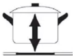
natural_image
Simple line drawing of a cooking pot with upward and downward arrows indicating direction (no text or symbols)natural_image
Four-panel kitchen gas stove with circular vent and control knobs (no text or symbols visible)
natural_image
Four circular industrial gauges with cross-shaped cutouts and a central crosshair, shown from top-down perspective (no text or symbols)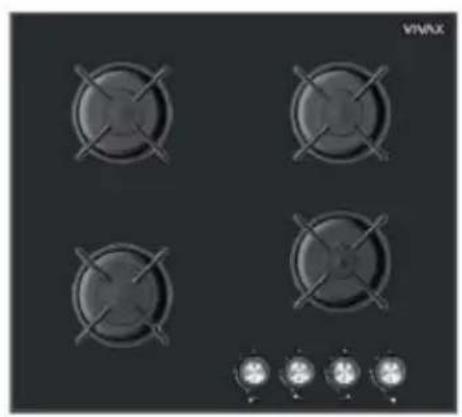
natural_image
Four identical gas stove fans arranged in a 2x2 grid on a dark background, with a small indicator light below (no text or symbols on the fans or background)
natural_image
Four black circular gas stove covers arranged in a 2x2 grid, with a row of circular icons below (no text or symbols on covers)OPOZORILO:
VZDRŽEVANJE STEKLOKERAMIČNIH PLOŠČ:
natural_image
Warning symbol with exclamation mark inside a triangle (no text or numbers)VARNOSTNA OPOZORILA
natural_image
Diagram of a greenhouse with steam rising from a stove inside, showing airflow and ventilation (no text or symbols)
natural_image
Diagram of a house interior with a stove and airflow arrows, no text or symbols presentnatural_image
Diagram showing a window mounted on a beam with a magnified inset illustrating the structural detail (no text or symbols)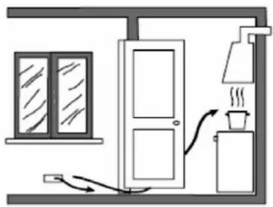
natural_image
Simple line drawing of a room with a window, door, and steaming cup (no text or symbols)natural_image
Pure technical diagram showing a rectangular block with labeled points A and B, no text or symbols presentnatural_image
Diagram of a layered structure with circular elements and dots, no visible text or symbolsTesnilni trak.


natural_image
Technical line drawings of mechanical components and structural elements (no text or symbols)Opozorila
natural_image
Simple line drawing of a kitchen sink with a circular component and a cross symbol (no text or labels)
natural_image
Diagram of a mechanical device with concentric rings and a downward arrow indicating motion (no text or symbols)natural_image
Pure diagram of a cooking pot with crossed arrows indicating direction (no text or symbols)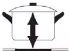
natural_image
Simple line drawing of a cooking pot with upward and downward arrows indicating direction (no text or symbols)Velikosti plovil
natural_image
Symbol of a train or bridge with a cross mark, no text or numbers presentSLABO

SLABO

natural_image
Symbolic icon of a traditional Chinese pot with crossed x-bracing (no text or symbols)PRAVILNO

natural_image
Simple black-and-white illustration of a cooking pot (no text or symbols)-
Namestite krono gorilnika (4) na skodelico gorilnika (5) tako, da se vžigalna naprava in naprava za nadzor plamena ujemata z ustreznimi luknjami na kroni gorilnika. Krona gorilnika mora pravilno sedeti na mestu.
-
Pokrov gorilnika (1,2,3) namestite na krono gorilnika (4) tako, da se pritrdilni izrastki ujemajo z ustreznimi vdolbinami.

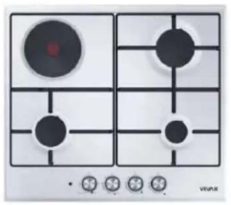
Gas/Electric and Gas
natural_image
Four-panel kitchen gas stove with circular vent and control knobs (no text or symbols visible)
natural_image
Four circular industrial gauges with crosshair indicators and a central target symbol, displayed on a dark background (no text or labels)
natural_image
Four identical electric stove fans arranged in a 2x2 grid on a dark background, with no visible text or symbols.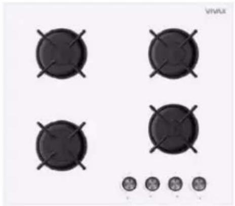
natural_image
Four black circular gas stove covers arranged in a 2x2 grid, with no visible text or symbols on the covers or background.WARNING:
MAINTENANCE CERAMIC SURFACE
Do not allow sugar, sauces or juices to burn on the glass cooking plate.
This can DAMAGE the glass surface or even melt of the glass surface or make subsequent cleaning much more difficult!
The light color change on the plate are normal and don't have any influence on working performances.
Dear Customer,
Pieces of packaging (plastic bags, polystyrene etc.) must not be left within reach of children, as they are potentially dangerous.
Please dispose of packaging thoughtfully by the appropriate means.
To this effect, we recommend that you read the entire guide carefully before operating the product and keep it as a reference. If you transfer the device to a third party, please give them this manual, to the new owner familiar with the device functions and warnings relevant to the safe use of the device.
This user manual is prepared for more than one model. Some of the features specified in the Manual may not be available in your appliance.
THIS APPLIANCE SHALL BE INSTALLED IN ACCORDANCE WITH THE REGULATIONS IN FORCE AND ONLY USED IN A WELL VENTILATED SPACE. READ THE INSTRUCTIONS BEFORE INSTALLING OR USING THIS APPLIANCE
Prior to installation, ensure that the local distribution conditions (nature of the gas and gas pressure) and the adjustment of the appliance are compatible!
The adjustment conditions for this appliance are stated on the label (or data plate) on the product
This appliance is not connected to a combustion products evacuation device. It shall be installed and connected in accordance with current installation regulations. Particular attention shall be given to the relevant requirements regarding ventilation
Gas types: LPG G30 – 30 mBar
NG (Natural Gas) G20 - 20 mBar
Factory settings: LPG G30-30mBar

natural_image
Warning symbol with exclamation mark inside a triangle (no text or numbers)IMPORTANT WARNINGS
- These instructions are only valid if the country symbol appears on the appliance. If the symbol does not appear on the appliance, it is necessary to refer to the technical instructions which will provide the necessary instructions concerning modification of the appliance to the conditions of use of the country.
- The cooker should be used according to operating instructions
• WARNING: This appliance must be earthed!
- Please find required information as power and ratings for your device from rating label is which located behind of appliance.
- Ensure that the electricity supply is turned OFF before installing your appliance.
- If the supply cord is damaged, it must be replaced by the manufacturer, its services agent or similar qualified persons in order to avoid hazard.
- Keep the electrical cable of your cooker away from the hot areas; do not let them touch the appliance. Keep them away from sharp sides and heated surfaces.
- Keep the appliance and its power cord away from children less than 8 years old
- Connect the gas supply as close to the gas source as possible and check the gas connection for leakage. When checking the gas leakage, never use a lighter, match or cigarette. Check gas leakage with soap foam only!
- CAUTION: Usage of your appliance creates moisture, heat and products of combustion in the room in which it is installed; make sure that your kitchen is well ventilated.
- Prolonged intensive use of the appliance may call for additional ventilation, for example opening increasing the level of mechanical ventilation where present.
- When the cooker is hot never touch the cooker glass by hand.
- CAUTION: This appliance is for cooking purposes only. It must not be used for other purposes, for example room heating. All our appliances are only for domestic use, not for commercial use.
- Before starting to use your appliance, keep curtains, paper or inflammable things away from your appliance. Do not keep combustible or inflammable things in or near the appliance.
- This appliance can be used by children aged from 8 years and above and persons with reduced physical, sensory or mental capabilities or lack of experience and knowledge if they have been given supervision or instruction concerning use of the appliance in a safe way and understand the hazards involved.
• Children shall not play with the appliance. - Cleaning and user maintenance shall not be made by children without supervision.
- Use glove when using cooker. Do not touch on hot surfaces
- Do not use cooker in potentially explosive atmospheres.
- Do not heat closed cans and glass jars. The pressure may lead jars to explode.
- If the current rate of the fuse in your installation is less than 16 Amp, have a qualified electrician fit a16 Amp fuse (for devices with Electric hot plates).
- When the appliance is being used, some parts may become hot; children should be kept away and supervised at all times.
- Do not splash cool water on the hot surface surface of the appliance. Arising steam may cause burns and sudden temperature exchange may cause damages on the surface of the appliance
- WARNING: The appliance and its accessible parts become hot during use. Care should be taken to avoid touching
heating elements. Children less than 8 years of age and pets shall be kept away unless continuously supervised.

- Cleaning or user maintenance of the appliance
shall not be performed by children unless they are older than 8 years and supervised by adults
- Do not use harsh abrasive cleaners or sharp metal scrapers to clean the oven door glass since they can scratch the surface which may result in shattering of the glass.
- On burners or electric hot plates should not put unstable or deformed pots to prevent their roll over, which can cause injury.
- This appliance is produced in accordance with the safety regulations. Incorrect use will harm people and appliance.
- The appliance must be supplied via a suitable double pole isolating switch, having contact separation of at least 3 mm in all poles placed in a readily accessible position adjacent to the unit (for devices with Electric hot plates).
- Children should be supervised to ensure that they do not play with the appliance. Never let them play with the appliance.
- The cooking hob may be located in a kitchen, a kitchen/diner or bed-sitting room but not in a room containing a bath or shower.
- Caution: glass lids may shatter when heated.
Turn off all the burners before shutting the lid (if exist with device). Any spillage should be removed from the lid before opening.
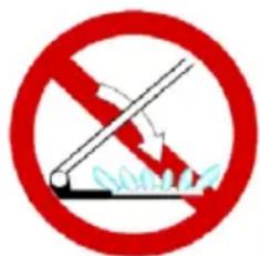
- CAUTION: Cooking process shall be
supervised. Do not leave cooker hob unattended!
- Bread may catch fire if the toasting time is too long. Close supervision is necessary during toasting
- WARNING: Before obtaining access to terminals, all supply circuits must be disconnected.
- WARNING: Unattended cooking on a hob with fat or oil can be dangerous and may result in fire. NEVER try to extinguish
a fire with water, but switch off the appliance and then cover flame e.g. with a lid or a fire blanket (wet kitchen cloth).
- WARNING: Danger of fire: do not store flammable, combustible, explosive liquid able or deformable by heat on the cooking surfaces.
- CAUTION: If the surface or glass ceramic is cracked, switch off the appliance to avoid the possibility of electric shock. Shut immediately off all burners and any electrical heating element and isolate the appliance from the power supply, do not touch the appliance surface, do not use the appliance!
WARNING: This appliance is not intended for use by persons (including children) with reduced physical, sensory or mental capabilities, or lack of experience and knowledge, unless they have been given supervision or instruction concerning use of the appliance by a person responsible for their safety.
- Children should be supervised to ensure that they do not play with the appliance. Do not put objects that children may reach on the appliance.
- Never place an empty pan on the burner or electric. panel that works. Do not place metal utensils such as knife, fork, spoon on the surface of the appliance, since they will get hot.
- Do not attempt to repair the appliance yourself, please contact an authorized service center. Contact an authorized service center and insist on the use of original spare parts.
- The appliance is not intended to be operated by means of an external timer or separate remote-control system
- To clean the appliance, do not use steam cleaners
- WARNING: Use only the type of gas listed on the label located on the back of the appliance. If your gas type is another type or specification, before starting to use appliance, you should replace the nozzles.
- Connect the unit to the gas installation, replace the nozzles and adjust the minimum flame proceed to a qualified service person only!
POSITION OF THE APPLIANCE
Before you start to use appliance, please carefully read "IMPORTANT AND SAFETY WARNINGS" chapter!
Before using hob plate, please remove all flammable tapes, styrofoam or any other ambalage materials on cooker. Also take out user manual and other flammable materials from appliance.
The appliance must not be installed close to the decorative doors or cabinets.
This device should use only after you installed into kitchen cabinet or base.
Allow disconnection of the appliance after installation, by accessible plug or switch in the fixed wiring.
ACCESSORIES
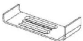
Bracket x4

Screw x4


NG Injectors (NG Gas)

NG Gas-pipe
Bend x 1

Instruction Manual x 1
Product Fiche
INSTALLATION OF YOUR COOKER
ELECTRICAL CONNECTION
- The adjustment conditions for this appliance are stated on the rating label.
- If you appliance is equipped with Electric Hot Plate, it requires 16 Ampere supply according to total power of your cooker. Please find all required values from rating label of your cooker. If necessary, installation by a qualified electrician is recommended.
- Electrical connection of the cooker should only be made to connections/sockets with an earth system installed in compliance with local regulations. If there are no connections/sockets with an earth system in place where the cooker will be installed, immediately contact a qualified electrician to install. The manufacturer is not responsible for damages that will arise because of the appliance not be connected to an earth system.
- Plug the appliance in a grounded socket protected by a fuse conforming to the values specified in the technical specifications chart.
- Have an authorized electrician set grounding equipment. Our company shall not be responsible for the damages that shall be incurred due to using the product without grounding according to local regulations.
- WARNING: If the surface is cracked, turn off the appliance to avoid risk of electric shock.
- Never wash the appliance by spraying or pouring water on it. There is a risk of electrocution.
- Do not touch the plug with wet hands. Do not pull the cord to plug off, always hold the plug.
- Unplug the unit during installation, maintenance, cleaning and repair.
-
Make sure the plug is inserted firmly into wall socket to avoid sparks.
-
If the power supply cord (the cord with plug) is damaged, this cord shall be replaced by the manufacturer or its service agent or an equally qualified personnel to prevent a hazardous situation.
- Do not use cut or damaged cords or extension cords other than the original cord.
- Do not use steam cleaners for cleaning the appliance, otherwise electric shock may occur.
- Make sure there is no liquid or humidity in the outlet where the product plug is installed.
- An omnipolar switch capable to disconnect power supply is required for installation. Disconnection from power supply shall be provided with a switch or an integrated fuse installed on fixed power supply according to building code.
- The power supply cord (the cord with plug) shall not contact the hot parts of the appliance.
- Unplug the unit during installation, maintenance, cleaning and repair.
- Appliance is equipped with a type "Y" cord cable.
- The circuit breaker switches of the cooker shall be placed so that end user can reach them when the cooker is installed.
- Fixed connections shall be connected to a power supply enabling omnipolar disconnection. For appliances with over voltage category below III, disconnection device shall be connected to fixed power supply according to wiring code.
- Do not remove ignition switches from the appliance. Otherwise, live electric cables can be accessed. It may cause an electric shock.
- Your hob is for use with 220-240V AC, 50Hz – 60 Hz electric supply. If your supply is different from the specified value, contact your authorized service agent. If your supply is different from the specified value, contact your authorized service agent.
- When placing your cooker to its location, ensure that it is built in at the counter level.
- Some models are supplied without a plug-an-lead set. In this case please use a flexible cable to suitable for connection to mono phase: H05 VV-F 3 G 2,5 mm2 or H05 VV-F 3 G 4 mm 2
GAS CONNECTION
CAUTION: THIS APPLIANCE MUST ONLY BE INSTALLED IN A PERMANENTLY VENTILATED ROOM IN COMPLIANCE WITH THE APPLICABLE REGULATIONS.
ALL KINDS OF OPERATIONS TO BE PERFORMED ON GAS INSTALLATION MUST BE PERFORMED BY AUTHORIZED AND COMPETENT PEOPLE.
This appliance is not connected to a combustion products evacuation device. It shall be installed and connected in accordance with current installation regulations. Particular attention shall be given to the relevant requirements regarding ventilation.
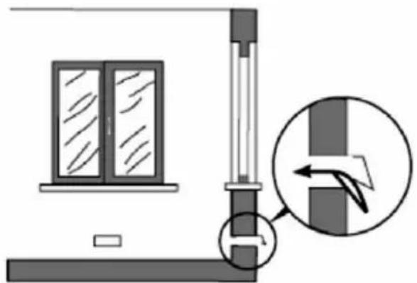
The use of a gas cooking appliance results in production of heat and moisture in the room in which it is installed. Ensure that the kitchen is well ventilated: keep naturel ventilation holes open or install a mechanical ventilation device (mechanical exrtactor hood)

natural_image
Diagram of a greenhouse with a stove, air ducts, and cooling tower (no text or symbols)
natural_image
Diagram of a house interior with a stove, airflow arrows, and roof structure (no text or symbols)Prolonged intervise use of the appliance may call for additional ventilation, for example opening of a window, or more effective ventilation, for example increasing the level of mechanical ventilation where present.
| Room size Ventilating opening | |
| Smaller than 5m3 Min. 100 cm | 2 |
| Between 5m3 - 10m3 Min. 50 cm | 2 |
| Bigger than 10m3 No need | |
| In basement or Cellar Min. 65 cm | 2 |
Connection and Security:
natural_image
Diagram showing a window and vertical structure with an arrow indicating direction, no text or symbols present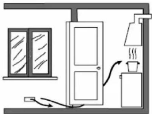
natural_image
Simple line drawing of a room with a window, door, lamp, and coffee cup (no text or symbols)- Prior to installation, ensure that the local distribution conditions (nature of the gas and gas pressure) and the adjustment of the appliance are compatible
- The adjustment conditions for this appliance are stated on the label (or data plate)
- This appliance is not connected to a combustion products evacuation device. It shall be installed and connected in accordance with current installation regulations. Particular attention shall be given to the relevant requirements regarding ventilation
- Fit the clamp to the hose. Push one of the hose until it goes to the end of the pipe.
- For the sealing control; ensure that the control buttons in the control panel are closed, but the gas cylinder is open. Apply some soap bubbles to the connection. If there is gas leakage, there will be foaming in the soaped area.
- The cooker should be using a well ventilation place and should be install on flat ground.
-
Re-inspect the gas connection.
-
When placing your cooker to its location, ensure that it is at the counter level. Bring it to the counter level by adjusting the feet if necessary.
-
Do not make gas hose and electrical cable of your cooker go through the heated areas, especially through the behind of the cooker. Do not move gas connected cooker. Since the forcing shall loosen the hose, gas leakage may occur.
-
Please use flexible hose for gas connection.
-
Connect your cooker to LPG in shortest way and without any leakage. Min. 40 cm Max. 125 cm.
-
When making gas leakage check, never use any flame type like those of lighter, matches, cigarette fire or similar ones.
-
Do not shut lid when burner a light Caution: glass lids may shatter when heated. Turn off all the burners before shutting the lid.
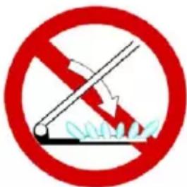
-
The mechanism cannot be run for longer than 15 seconds. If the burner is not on after 15 seconds, stop the mechanism and wait for at least one minute before trying to ignite the burner again.
-
For proper operation, hood, gas pipe and clamp should be replaced periodically accordint to manufacturer recommendations and when required.
-
Gas should burn well in gas products. Well burning gas can be understood from blue flame and continuous burning. If gas does not burn sufficiently, carbon monoxide (CO) can be generated. Carbon monoxide is a colourless, odourless and very toxic gas; even small amounts have lethal effect.
-
Ask your local gas supplies about the phone numbers for emergencies related to gas and the measures to be taken upon gas odour is detected.
What To Do When Gas Odour Is Detected
- Do not use naked flame, and do not smoke.
- Do not operate any electrical switch. (For example: lamp switch or doorbell)
- Do not use telephone or mobile phone.
- Open the doors and windows.
-
Close all valves on the appliances that utilize gas and the gas counters.
-
Check all hoses and their connections against leaks. If you still smell gas, leave the house and warn your neighbours.
- Call fire brigade from a telephone outside the home.
- Do not enter into the house until authorities clarify it is safe.
Intended Use
- This product is designed for home use. Commercial use of the appliance is not permitted.
- This appliance may only be used for cooking purposes. It shall not be used for other purposes like heating a room.
- The manufacturer assumes no responsibility for any damage due to misuse or mishandling.
- Operational life of the product you have purchased is 10 years. This is the period for which the spare parts required for the operation of this product as defined is provided by the manufacturer.
Electrical connection
Wiring diagram
The wires in the mains lead are coloured in accordance with following code:
The wire which is coloured GREEN and YELLOW must be connected to the terminal which is marked with the letter E or by the Earth symbol.

IMPORTANT:
When the power cord is damaged it must be replaced by the manufacturer to produce, customer service agent or similarly qualified personnel.
- Setting conditions of this appliance is indicated in tag or data plate.
-
Your appliance should be plugged in a fuse appropriate for electric power. If necessary, it is recommended that installation is done by authorized service.
-
Your appliance is configured in accordance with electrical supply of 220-240V 50/60Hz. If main electrical network is different from these values, contact with your authorized service.
- Electrical connections of your appliance should only be made to the fuses having suitably wired grounding (grounded) system. If no convenient fuse is available in the place where your appliance is to be installed, contact with authorized service immediately. Manufacturing firm is not responsible definitely for the damages that fuses whose grounding is not made and connected to the appliance can cause.
- Plug of the appliance should be close to be accessed easily to the fuse whose grounding is made without use of extension cord.
- Do not allow contacting the power cable of your appliance with hot regions. Similarly, keep away it from sharp edges and corners.
- If feeder cord is damaged, this cord should be replaced either by manufacturer or its service agency or same degree qualified personnel in order to hinder a dangerous situation.
- Wrong electrical connection may give damage to the appliance. In this case, your appliance will remain out of guarantee scope. Electrical connection of your appliance should be done by authorized service.
Get electrical connection of your appliance done to authorized person in line with the following scheme.
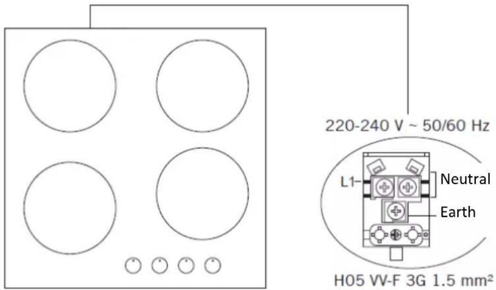
Gas connection

WARNING: Before starting any work related with gas installation, turn off gas supply. Risk of explosion
This appliance must be installed and connected in accordance with installation regulations in force in the country in which the appliance is to be used.
This appliance is supplied to run on LPG and natural gas.
Conversions for use on LPG and natural gases must only be undertaken by qualified person.
IMPORTANT:
It is the law that all gas appliances are installed by competent persons in accordance with the current edition of the Gas Safety Installation and Use Regulations. It is in your interest and that of safety to ensure compliance with the law!
- Connect your appliance to gas cock from the shortest way and in a manner to prevent any leakage. For safety, the hose used should be maximum 125 cm and minimum 40 cm.
- While making gas leakage control; never use lighter, match, glowing cigarette or similar inflammable matter.
- Apply soap bubble on connection point. If any leak/leakage exists, foaming will occur on soaped region.
- If the cooktop is to be mounted on a cabinet or openable drawer, a heat protection panel having 15 mm minimum opening should be mounted under the cooktop.
WARNING: Gas hose and electric connection of the appliance should not pass next to hot areas such as back of the appliance. Gas hose should be connected by making wide angle turns against breaking possibility. Movement of appliance whose gas connection is made may cause gas leakage.

WARNING: Natural gas connection should be done by authorized service.
For natural gas connection, place gasket in the nut at the edge of natural gas connection hose. To install the hose on main gas pipe, turn the nut. Complete the connection by making gas leakage control.
LPG Connection

NG Connection

Gas adjustment

Take precautions on the operations and adjustments to be carried out when converting from one gas to another.
All work must be carried out by qualified technician. Before you begin, turn off the gas and electricity supply to the appliance.

Change the injector of the burners
Remove the pan support, Burner lid and Flame spreader:
- Unscrew the injector using a 7mm box spanner and replace it with the stipulated injector for new gas supply. Carefully reassemble the all components.
- After injectors are replaced, it is advisable to strongly tighten the injector in place.
Adjustment of minimum level of the flame

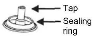

- Turn the taps down to minimum.
- Remove the knob from the tap and place a small bladed screwdriver in the centre of the tap shaft.
- The correct adjustment is obtained when the flame has a length of about 6 - 7 mm.
For butane / propane gas (LPG), turn the screw clockwise. Refit the control knob.
For natural gas, turn the screw one time counter clockwise. At low position, length of normal flame should be 6-7 mm
Make sure that the flame does not go out by quickly turning from maximum flow to minimum flow. If it does then remove the control knob and make further adjustments to the gas flow, testing it again once the adjustment has been made. - Repeat this process for each one of the gas taps.
IMPORTANT
Do not dismantle the tap shafe: in the event of malfunction, change the whole tap. Before placing the burners back on the top place, make sure that the injector is not blocked.
A full operational test and a test for possible leakages must be carried out after gas conversion (such as soap water or gas detector).
After completing conversion, a qualified technician or installer has to mark "V" on the right gas category to match with the setting in rating plate. Remove the previous setting "V" mark.
| Burner Specification | G20, 20 mBar G25, 25 mBar | G20, 25 mBar G20,13 mBar | ||||||
| Natural gas (NG) Natural gas (NG) Natural gas (NG) | ||||||||
| Wok burner (3,5) | Injector 1,40 | mm | 1,28 | mm | 1,60 mm | |||
| Gas flow 0,333 | m | 3/h | 0,333 | m3/h | 0,333 m3/h | |||
| Power 3,50 | kW | 3 | 50 kW | 3 | 50 kW | |||
| Wok burner (23,5) | Injector 1,15 | mm | 1,06 | mm | 1,35 mm | |||
| Gas flow 0,243 | m | 3/h | 0,243 | m3/h | 0,243 m3/h | |||
| Power 2,50 | kW | 2 | 50 kW | 2 | 50 kW | |||
| Rapid burner | Injector 1,15 | mm | 1,10 | mm | 1,45 mm | |||
| Gas flow 0,276 | m | 3/h | 0,276 | m3/h | 0,276 m3/h | |||
| Power 2,90 | kW | 2 | 90 kW | 2 | 90 kW | |||
| Semi Rapid burner | Injector 0,97 | mm | 0,92 | mm | 1,10 mm | |||
| Gas flow 0,162 | m | 3/h | 0,162 | m3/h | 0,162 m3/h | |||
| Power 1,70 | kW | 1 | 70 kW | 1 | 70 kW | |||
| Auxiliary burner | Injector 0,72 | mm | 0,70 | mm | 0,85 mm | |||
| Gas flow 0,96 | m | 3/h | 0,96 | m3/h | 0,96 m3/h | |||
| Power 0,95 | kW | 0.95 | kW | 0.95 | kW | |||
| Burner Specification | G30, 28-30 mBar G31, 37 mBar | G30, 50 mBar G30, 37 mBar | |||||
| LPG | LPG | LPG | |||||
| Wok burner (3,5) | Injector 0,96 | mm | 0,76 | mm | 0,96 | mm | |
| Gas flow | 254 | g/h | 254 | g/h | 254 | g/h | |
| Power | 3,50 | kW | 3,50 | kW | 3,50 | ||
| Wok burner (23,5) | Injector 0,82 | mm | 0,73 | mm | 0,78 | mm | |
| Gas flow | 182 | g/h | 182 | g/h | 182 | g/h | |
| Power | 2,50 | kW | 2,50 | kW | 2,50 | ||
| Rapid burner | Injector 0,85 | mm | 0,75 | mm | 0,85 | mm | |
| Gas flow | 211 | g/h | 211 | g/h | 211 | ||
| Power | 2,90 | kW | 2,90 | kW | 2,90 | ||
| Semi Rapid burner | Injector 0,65 | mm | 0,60 | mm | 0,65 | mm | |
| Gas flow | 124 | g/h | 124 | g/h | 124 | g/h | |
| Power | 1,70 | kW | 1,70 | kW | 1,70 | ||
| Auxiliary burner | Injector 0,50 | mm | 0,43 | mm | 0,50 | mm | |
| Gas flow | 69 | m3 /h | 69 | g/h | 69 | g/h | |
| Power | 0,95 | kW | 0,95 | kW | 0,95 | ||
| Ceramic | |||||||
| 180mm Ceramic heater | 1800 W | ||||||
| 140mm Ceramic heater | 1200 W | ||||||
| 120/180mm Ceramic heater | 1700 W | ||||||
| 140/250mm Ceramic heater | 1800 W | ||||||
| Hot | |||||||
| Level 1 Level 2 Level 3 Level 4 Level 5 Level 6 | |||||||
| ∅145 mm hotplate 95 W 155 W 250 | W 400 W 750 | W 1000 W | |||||
| ∅145 mm rapid hotplate 135 W 165 | W 250 W 500 | W 750 W 1500 | W | ||||
| ∅180 mm hotplate 115 W 175 W 250 | W 600 W 850 | W 1500 W | |||||
| ∅180 mm rapid hotplate 175 W 220 | W 300 W 850 | W 1150 W 2000 | W | ||||
| Supply voltage 220-240 V 50/60 Hz. | |||||||
Heater
Plates
WARNING: Diameter values written on the injector are specified without a comma. For example; The diameter of 1,70 mm is specified as 170 on the injector.
WARNING: For the modification to be done by authorized service, this table should be considered. Manufacturer may not be held responsible for any problems rising because of any faulty modification.
WARNING: In order to increase the product quality, the technical specifications may be changed without prior notice.
WARNING: The values provided with the appliance or its accompanying documents are laboratory readings in accordance with the respective standards. These values may differ depending on the use and ambient conditions.
INSTALLATION
Selection of installation equipment
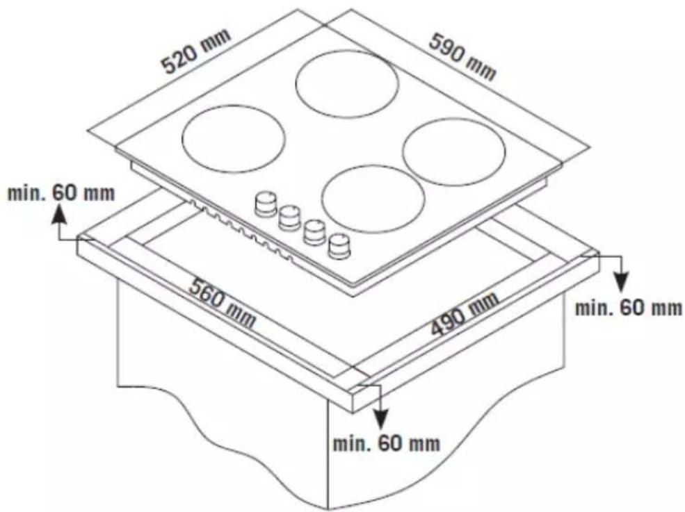
- Cut out the work surface according to the sizes shown in the drawing.
For the purpose of installation and use, a minimum of 50mm space shall be preserved around the hole. Be sure the thickness of the work surface is at least 30mm. Please select heat-resistant work surface material to avoid larger deformation caused by the heat radiation from the hotplate. As shown below:
- The cooker hob can be used on the table top of cabinet. The hob should be placed horizontally. As shown below:

natural_image
Pure technical diagram showing a rectangular block with labeled dimensions A and B, no text or symbols present.Under any circumstances, make sure the ceramic cooker hob is well ventilated and the air inlet and outlet are not blocked. Ensure the ceramic cooker hob is in good work state. As shown below.
Note: The safety distance between the hotplate and the cupboard above the hotplate should be at least 650mm.

| A (mm) (min) | B (mm) | C (mm) | D E | ||
| 650 | 50 mini | 30mini | Air intake | Air exit | 10 mm |
Before locating the fixing brackets
The unit should be placed on a stable, smooth surface (use the packaging). Do not apply force onto the controls protruding from the hob.
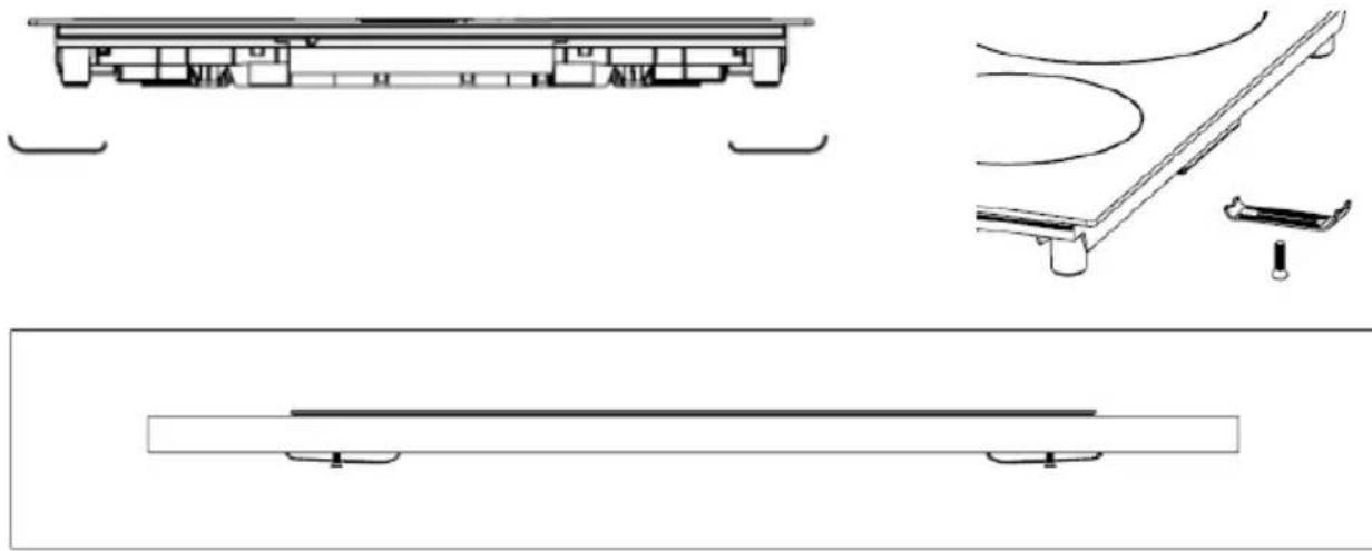
Fix the hob on the work surface by screw four brackets on the bottom of hob (see picture) after installation. Adjust the bracket position to suit for different work surface's thickness.
-
Put sealing track on the edge of t he hob
-
Attach the worktop to the worktop using the brackets provided in the accessory, as shown in the illustration below.

natural_image
Diagram of a mechanical component with a coiled spring and mounting base (no text or symbols)Sealing tape.


natural_image
Technical line drawings of mechanical components and structural elements (no text or symbols)Cautions
- The cooker hob must be installed by qualified personnel or technicians. We have professionals at your service. Please never conduct the operation by yourself.
- The cooker hob shall not be mounted to cooling equipment, dishwashers and rotary dryers.
- The cooker hob shall be installed such that better heat radiation can be ensured to enhance its reliability.
- The wall and induced heating zone above the work surface shall withstand heat.
- To avoid any damage, the sandwich layer and adhesive must be resistant to heat.
- A steam cleaner is not to be used.
- This ceramic can be connected only to a supply with system impedance no more than 0.427 ohm. In case necessary, please consult your supply authority for system impedance information.
Main Parts
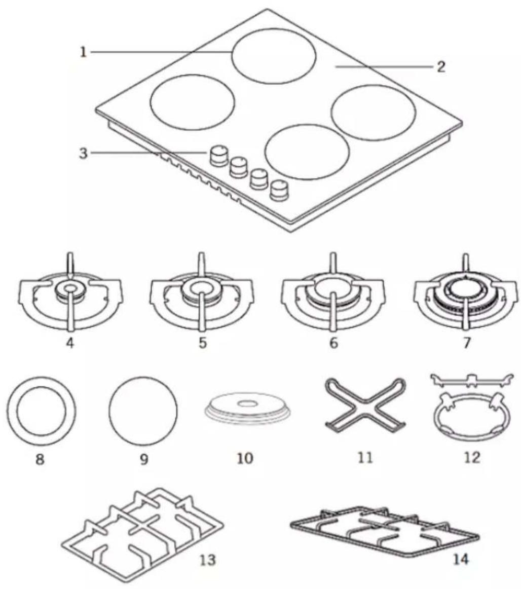
- Burner position 8. Dual zone Ceramic heater (120 mm /
180 mm)*
-
Glass or Metal surface
-
Ceramic heater / Hot Plate (180 or 145 mm) *
-
Control buttons 10.
Hot Plate 140 or 180 mm *
-
Small burner 1
-
Coffe adaptor *
-
Medium burner
-
Wok buirner adaptor *
-
Large burner 13.
Cast Iron pan support *
-
Wok burner
-
Enamel pan support *
How to use the appliance
The following symbols will appear on the control panel, next to each control handle:
- Black circle: gas off
Large flame: maximum setting
A Small flame: minimum setting
Model: 4 Gas burner:

flowchart
graph TD
    A["Step 1"] --> B["Circle Node"]
    C["Step 2"] --> D["Circle Node"]
    E["Step 3"] --> F["Circle Node"]
    G["Step 4"] --> H["Circle Node"]
- Front left burner
- Rear left burner
- Rear Right burner
- Front Right burner
Model: 3 Gas burner + 1 Ceramic heater / Hot Plate

flowchart
graph TD
    A[" "] --> B[" "]
    B --> C[" "]
    B --> D[" "]
    B --> E[" "]
    B --> F[" "]
    B --> G[" "]
    B --> H[" "]
    B --> I[" "]
    B --> J[" "]
    B --> K[" "]
    B --> L[" "]
    B --> M[" "]
    B --> N[" "]
    B --> O[" "]
    B --> P[" "]
    B --> Q[" "]
    B --> R[" "]
    B --> S[" "]
    B --> T[" "]
    B --> U[" "]
    B --> V[" "]
    B --> W[" "]
    B --> X[" "]
    B --> Y[" "]
    B --> Z[" "]
    B --> AA[" "]
    B --> AB[" "]
    B --> AC[" "]
    B --> AD[" "]
    B --> AE[" "]
    B --> AF[" "]
    B --> AG[" "]
    B --> AH[" "]
    B --> AI[" "]
    B --> AJ[" "]
    B --> AK[" "]
    B --> AL[" "]
    B --> AM[" "]
    B --> AN[" "]
    B --> AO[" "]
    B --> AP[" "]
    B --> AQ[" "]
    B --> AR[" "]
    B --> AS[" "]
    B --> AT[" "]
    B --> AU[" "]
    B --> AV[" "]
    B --> AW[" "]
    B --> AX[" "]
    B --> AY[" "]
    B --> AZ[" "]
    B --> BA[" "]
    B --> BB[" "]
    B --> BC[" "]
    B --> BD[" "]
    B --> BE[" "]
    B --> BF[" "]
    B --> BG[" "]
    B --> BH[" "]
    B --> BI[" "]
    B --> BJ[" "]
    B --> BK[" "]
    B --> BL[" "]
    B --> BM[" "]
    B --> BN[" "]
    B --> BO[" "]
    B --> BP[" "]
    B --> BQ[" "]
    B --> BR[" "]
    B --> BS[" "]
    B --> BT[" "]
    B --> BU[" "]
    B --> BV[" "]
    B --> BW[" "]
    B --> BX[" "]
    B --> BY[" "]
    B --> BZ[" "]
    B --> CA[" "]
    B --> CB[" "]
    B --> CC[" "]
    B --> CD[" "]
    B --> CE[" "]
    B --> CF[" "]
    B --> CG[" "]
    B --> CH[" "]
    B --> CI[" "]
    B --> CJ[" "]
    B --> CK[" "]
    B --> CL[" "]
    B --> CM[" "]
    B --> CN[" "]
    B --> CO[" "]
    B --> CP[" "]
    B --> CQ[" "]
    B --> CR[" "]
    B --> CS[" "]
    B --> CT[" "]
    B --> CU[" "]
    B --> CV[" "]
    B --> CW[" "]
    B --> CX[" "]
    B --> CY[" "]
    B --> CZ[" "]
- Front left Ceramic heater
- Rear left burner
- Rear Right burner
- Front Right burner
Note: The control panels above is only for illustration purposes.
Consider the control panel on your device
Before starting to use your cooktop, be sure burner hoods are at correct position. Correct placement of burner hoods are shown in the following figure

natural_image
Simple line drawing of a mechanical component with a cross mark, no text or symbols present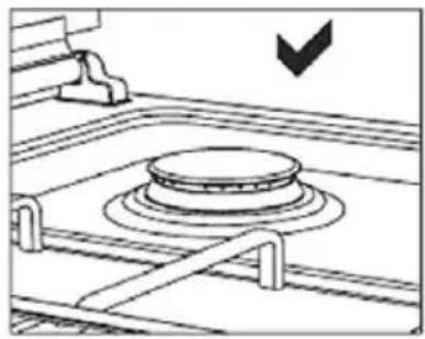
natural_image
Diagram of a mechanical device with a circular component and lever mechanism (no text or symbols)Pay attention that cooktop grills are placed on cooktop table completely. In case of failure about this matter can cause pouring of the materials to be put on that
• The minimum setting is at the end of the anti-clockwise rotation of the control handle.
- All operation positions must be selected between the maximum and minimum position.
- The symbol on the control panel, next to the control handle will indicate which burner it operates.
- The appliance is equipped with an electronic ignition device. Simply press and turn the knob anti-clockwise to the maximum flame symbol until it is switched on. If the burner does not light up in the first 15 seconds, turn the knob to ● and do not attempt to restart for 60 seconds.
Once the ignition is switched on, keep the knob pressed for a few seconds to allow the thermocouple to heat up.
- It may happen that the burner hoes out when the knob is released, it means that the thermocouple (FFD Device) has not heated up enough. Wait a few moments and repeat the operation; keep the knob pressed for longer.
- In the event of an accidental switch-off, a safety device blocks the gas outlet even when the tap is open.

Return the knob to and do not attempt to restart for 60 second s.
Power level for the Caramic / Eelectric cooking area \*

Off Position
1-9 / 1-6) Power values Ceramic / Hot plate

Turn On Dual zone \*
Turn the knob until the desired power level is set.
Turning the ceramic hobs off
Turn the relevant hob knob to off ( ●) position

* Option, not apply on all models. The pictures above are only for illustration purposes. Consider the control panel on your device
Notes and Recommendations:
- While using coffee pot apparatus supplied along with the cooktop, be sure that foots of apparatus are placed on cooktop grill exactly and remain on cooktop zone in centred way. Use the apparatus only on small burner.
- While utilizing gas cooktops, use saucepan, placed on cooktop surface as far as possible. Thanks to that, you can save energy. In the following table, cooking pot diameters recommended to be used as per burners are given. Characteristic of Wok cooktop zone is to cook quickly.
- Ensure that the grates are fully seated on the cooktop plate. If the grate is not properly seated, this may cause spillage of materials placed on it.
- Place the pots and pans so that their handles are not placed above the hobs to prevent heating of the handles.
- Place suitable amount of food to the pots and pans. Thus, you may prevent overflowing of meals and avoid unnecessary cleaning.
- The size of the container and the gas flame shall match each other. Set gas flames so that they do not extend further than the base of the container.
- Do not use containers that are unstable and that may be easily tipped over on the cooktop.
- Do not put empty pots and pans on the hobs with their flames on.
• Always turn off the hobs after each use.
- Do not put containers that may be affected by heat on the product.
- Do not operate the hobs without any pots and pans placed on them.
- Do not place the lids of the pots and pans on the hobs.
- When you want to put the pot on another hob, take the pot up and place it again instead of sliding it.
- Keep the lid of container you use for heating oil open.
- Do not put oil with a volume more than one third of the pan. Do not leave the oil unattended when the oil is being heated. Extremely hot oils may cause fire.

natural_image
Pure diagram of a cooking pot with crossed arrows indicating direction (no text or symbols)
natural_image
Simple line drawing of a cooking pot with upward and downward arrows indicating direction (no text or symbols)- Use pots and pans with machined bases only. Sharp edges cause scratches on the surface.
- Do not use aluminium pots and pans on Glass surface. Aluminium cause damages to the hob surface.
Pot Sizes
Recommended pot diameters to be used are provided in the following tables
| Burner | Pan diameterGlass Hob | Pan diameterMetal Hob |
| Small bruner 12-18 | cm 12-18 cm | |
| Middle burner 18-20 | cm 18-22 cm | |
| Big burner 22-24 cm | 22-26 cm | |
| Wok burner 24-26 | cm 26-32 cm |
WARNING: Cooking pot to be used with products should have minimum 120 mm diameter
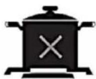
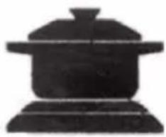
CORRECT DISHES POSITION AND USAGE

WRONG WRONG WRONG CORRECT
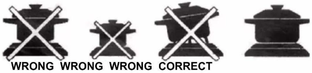
- Do not use cookware with jagged edges or a curved base.
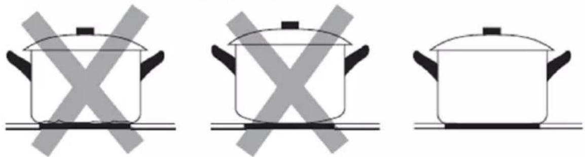
Make sure that the base of your pan is smooth, sits flat against the glass, and is the same size as the cooking zone. Always centre your pan on the cooking zone.

COOKING GUIDELINES

Take care when frying as the oil and fat heat up very quickly, particularly if you're using the highest power level. At extremely high temperatures oil and fat will ignite spontaneously and this presents a serious fire risk.
1. Cooking tips
- When food comes to the boil, reduce the temperature setting.
• Using a lid will reduce cooking times and save energy by retaining the heat. - Minimize the amount of liquid or fat to reduce cooking times.
- Start cooking on a high setting and reduce the setting when the food has heated through.
IF THE APPLIANCE DOES NOT OPERATE
| Problem Problem Cause Solution | ||
| Not ignited | No Spark Check the electricity supply | |
| The burner lid is badly assembled | Assemble the lid correctly | |
| The gas supply is closed | Open the gas supply completely | |
| Badly ignited | The gas supply is not completely open. | Open the gas supply completely. |
| The burner lid is badly assembled. | Assemble the lid correctly. | |
| The ignition plug is contaminated with alien substance. | Wipe alien substance with a dry cloth. | |
| The burners are wet. Dry the burners lids carefully. | ||
| The holes in the flame spreader are clogged. | Clean the flame spreader. | |
| Noise made when combusted and ignited | The burner lid is badly assembled. | Assemble the burner lid correctly. |
| Flame goes out when in use. | The flame supervision device is contaminated with alien substance. | Clean the flame supervision device. |
| Product being cooked has boiled over and extinguished the flame. | Turn off burner knob.Wait one minute and reignite zone. | |
| A strong draught may have blown the flame out. | Please turn off zone and check cooking area for draught such as open windows.Wait one minute and reignite zone | |
| Yellow Flame | The holes in the flame spreader are clogged. | Clean the flame spreader. |
| Different gas is used. | Check the gas used. | |
| Unstable Flame | The burner lid is badly assembled. | Assemble the burner lid correctly. |
| Gas Smell | Gas leakage | Stop using the product and close the middle valve.Open the window to ventilate.Contact our service centre by using a phone outside. |
If the problem is not solved:
1) Cut the electricity connection of unit (turn off the circuit breaker) and turn off gas supply.
2) Call the manufacturer, its services agent or similar qualified persons
MAINTENANCE and CLEANING
Cleaning operations must only be carried out when the appliance is completely cool.
The appliance should be disconnected from your mains supply and turn off gas supply before commencing any cleaning process.
Clean your appliance after each use.
You should use:
Soft cloth
Neutral Detergent
You shouldn't use:
Nylon Brush
Edible Oil
Abrasive
Metal Brush
Acidic/Alkali Detergent
Thinner/Benzene
Cleaning pan support and Control handles
• Take of the Pan support
- Clean these and the control handles with a damp cloth, washing up liquid and warm water (for stubbon soiling, soak beforehand)
• Dry Everything with a clean soft cloth.
Cleaning Top plate
- Regularly wipe over the top plate using a soft cloth well wrung-out in warm water to which a little washing up liquid has been added
- Dry the top plate throughly after cleaning.
- Remove salty foods or liquids from the hob as soon as possible to avoid the risk of corrosion
- Stainless steel parts of the appliance may become discoloured over time. This is normal due to high temperatures.
Each time the appliance is used these parts should be cleaned with a product that is suitable for stainless steel.
Cleaning burners
- Remove the burner lids and Flame Spreaders by pulling them upwards and away from the top plate
- Soak them in hot water and a little neutral detergent
- After cleaning and washing them, wipe and dry them carefully. Make sure that the flame holes are clean and completely dry
- Wipe the fixed parts of the burner cup with a damp cloth and dry afterwards
- Gently wipe the ignition device and flame supervision device with a well wrung-out cloth and wipe dry with a clean cloth
- Before placing the burners back on the top plate, make sure that the injector is not blocked.
Re-assemble the Auxiliary, Semi-Rapid, Rapid and Wok burners as follows

- Place the flame spreader (4) on to the burner cup (5) so that the ignition device and the flame supervision device extend through their respective holes in the flame spreader. The flame spreader must click into place correctly.
- Position the burner lid (1,2,3) onto the flame spreader (4) so that the retaining pins fit into their respective recesses.

Replace parts in the correct order after cleaning:
- Do not mix up the top and bottom
— The locating pins must fit exactly into the notches
To clean the appliance, do not use steam cleaners
WARNING:
Do not allow sugar, sauces or juices to burn on the cooking plate. This can DAMAGE the glass surface or even melt of the glass surface or make subsequent cleaning much more difficult!
The light color change on the plate are normal and don't have any influence on working performances
TECHNICAL SPECIFICATION
| Model BH-31TEI X BH-31TVCCI | BH-40TEI G BH-40TEI GW | ||
| Cooking zones | 3 gas burners + 1 rapid hot plate | 3 gas burners + 1 Ceramic Dual zone | 4 gas burners |
| Power supply 220-240V~ 50Hz | |||
| Installed electric power 2000W 2100W | - | ||
| Dimensions WxHxD (mm) 590 x 520 x 5 | 5 mm | ||
| Installation dimensions AxB (mm) 560 x | 490 mm | ||
Disposal of Electrical and Electronic Equipment

To protect our environment and to recycle the raw materials used as completely as possible, the consumer is asked to return unserviceable equipment to the public collection system for electrical and electronic.
The symbol of the crossed indicates that this product must be returned to the collection point for electronic waste to feed it by recycling the best possible raw
material recycling.
By ensuring this product you will prevent possible negative effects on the environment and human health, which could otherwise be caused due to improper disposal of that product. The recycling of materials from this product, you will help to preserve a healthy environment and natural resources.
For detailed information about the collection of EE products contact the dealer where you purchased the product.
EU Declaraton of Conformity
This device is manufactured in accordance with the applicable European standards and in accordance with all applicable Directives and Regulations.
EU declaration of conformity can be downloaded from the following link: www.msan.hr/dokumentacijaartikala

JAMSTVENI LIST
VIVAX
HR
MODEL UREĐAJA
SERIJSKI BROJ
DATUM PRODAJE
BROJ RAČUNA PRODAVATELJA
POTPIS I PEČAT PRODAVATELJA
-
Ovim jamstvom M SAN Grupa kao davatelj jamstva u Republici Hrvatskoj jamči besplatan popravak istog u skladu s važećim propisima i u skladu s uvjetima opisanim u ovom jamstvenom listu.
Ovim jamstvom jamčimo da će predmet ovog jamstva raditi bez pogreške uzrokovane eventualnom lošom izradom ili lošim materijalom izrade. Svi, eventualno nastali, kvarovi biti će besplatno otklonjeni u ovlaštenom servisu u jamstvenom roku. -
UVJETI JAMSTVA Jamstveni rok počinje od dana kupnje proizvoda i traje:
| 60 MJESECI (5 godina) | HLADNJACI,VERTIKALNE I HORIZONTALNE LEDENICE |
| 36 MJESECI (3 godine) | SAMOSTOJEĆI ŠTEDNJACI, PERILICE I SUŠILICERUBLJA, PERILICE SUĐA, KUHINJSKE NAPEUGRADBENE PEĆNICE I PLOČE, KUHINJSKE NAPEGRIJALICE VODE |
-
U slučaju kvara na proizvodu koji je predmet ovog jamstva, obvezujemo se da ćemo isti popraviti u najkraćem mogućem roku, a najkasnije u roku od 45 dana. Ako se proizvod ne može popraviti ili se ne popravi u roku od 45 dana, biti će zamijenjen novim. Jamstvo će biti produženo za vrijeme trajanja popravka.
-
Jamstvo se priznaje samo uz račun o kupnji, te uz ovaj jamstveni list koji mora biti ispravno popunjen odnosno mora sadržavati datum prodaje, pečat i potpis prodavatelja.
-
JAMSTVO NE OBUHVAĆA
POTPIS I PEČAT PRODAVATELJA
GARANCIJSKA IZJAVA
-
Ovom garancijom garantira proizvođač proizvoda, preko KIM TEC d.o.o., kao uvoznika i davatelja garancije u Bosni i Hercegovini besplatan popravak istog u skladu s važećim propisima i u skladu s uvjetima opisanim u ovom garantnom listu. Ovom garancijom garantiramo da će predmet ove garancije raditi bez greške uzrokovane eventualnom lošom izradom i lošim materijalom izrade. Svi eventualno nastali kvarovi biti će besplatno otklonjeni u ovlaštenom servisu u garantnom roku.
-
UVJETI GARANCIJE: Garantni rok počinje teći od dana kupnje proizvoda i traje:
| 60 MJESECI (5 godina) | HLADNJACI,VERTIKALNE I HORIZONTALNE ŠKRINJE |
| 36 MJESECI (3 godine) | ŠTEDNJACI, PERILICE I SUŠILICE RUBLJA, PERILICESUĐA, KUHINJSKE NAPE, UGRADBENE PEĆNICE IPLOČE, GRIJALICE VODE |
- U slučaju kvara na proizvodu koji je predmet ove garancije, obavezujemo se da ćemo isti popraviti u najkraćem mogućem roku, a najkasnije u roku od 45 dana. Ako se proizvod ne može popraviti ili se ne popravi u roku od 45 dana, biti će zamijenjen novim.
- Garancija se priznaje samo uz račun o kupnji, te uz ovaj garantni list koji mora biti ispravno popunjen odnosno mora sadržavati datum prodaje, pečat i potpis prodavatelja.
- Davalac garancije osigurava servis i rezervne dijelove 7 godina od datuma kupnje.
GARANCIJA NE OBUHVAĆA:


- UPOZORENJE:
- SIGURNOSNA UPOZORENJA
- Upozorenja
- UPOZORENJE: ODRŽAVANJE STAKLOKERAMIČKE PLOČE
- Glavni delovi
- Upotreba uređaja
- Model: 4 gorionika:
- Model: 3 gorionika + 1 keramički grejač / grejna ploča
- Veličine posuda
- IZBOR ISPRAVNOG POSUĐA
- UPUTSTVO ZA KUVANJE
- ПРЕДУПРЕДУВАЊЕ:
- Предупредување
- УПАТСТВО ЗА ГОТВЕЊЕ
- PARALAJMËRIM:
- MIRËMBAJTJA E PJESËS/ PLLAKËS SË SIPËRME TË SHPORETIT VITROQERAMIKË
- PARALAJMËRIME TË RËNDËSISHME
- INSTALIMI I SHPORETIT TUAJ
- LIDHJA ELEKTRIKE
- Rregullimi i gazit
- Paralajmërime
- OPOZORILO:
- VZDRŽEVANJE STEKLOKERAMIČNIH PLOŠČ:
- VARNOSTNA OPOZORILA
- Opozorila
- Velikosti plovil
- WARNING:
- MAINTENANCE CERAMIC SURFACE
- THIS APPLIANCE SHALL BE INSTALLED IN ACCORDANCE WITH THE REGULATIONS IN FORCE AND ONLY USED IN A WELL VENTILATED SPACE. READ THE INSTRUCTIONS BEFORE INSTALLING OR USING THIS APPLIANCE
- IMPORTANT WARNINGS
- POSITION OF THE APPLIANCE
- ACCESSORIES
- INSTALLATION OF YOUR COOKER
- ELECTRICAL CONNECTION
- GAS CONNECTION
- Connection and Security:
- What To Do When Gas Odour Is Detected
- Intended Use
- IMPORTANT:
- Gas adjustment
- Change the injector of the burners
- Adjustment of minimum level of the flame
- IMPORTANT
- INSTALLATION
- Selection of installation equipment
- Before locating the fixing brackets
- Cautions
- How to use the appliance
- Model: 4 Gas burner:
- Model: 3 Gas burner + 1 Ceramic heater / Hot Plate
- Power level for the Caramic / Eelectric cooking area \*
- Off Position
- 1-9 / 1-6) Power values Ceramic / Hot plate
- Turn On Dual zone \*
- Turning the ceramic hobs off
- Notes and Recommendations:
- Pot Sizes
- CORRECT DISHES POSITION AND USAGE
- COOKING GUIDELINES
- Cooking tips
- If the problem is not solved:
- MAINTENANCE and CLEANING
- You should use:
- You shouldn't use:
- Cleaning pan support and Control handles
- Cleaning Top plate
- Cleaning burners
- Re-assemble the Auxiliary, Semi-Rapid, Rapid and Wok burners as follows
- TECHNICAL SPECIFICATION
- Disposal of Electrical and Electronic Equipment
- EU Declaraton of Conformity
- JAMSTVENI LIST
- VIVAX
- MODEL UREĐAJA
- SERIJSKI BROJ
- DATUM PRODAJE
- BROJ RAČUNA PRODAVATELJA
- POTPIS I PEČAT PRODAVATELJA
- GARANCIJSKA IZJAVA
- GARANCIJA NE OBUHVAĆA:
Brand : Vivax
Model : BH-40TEI GW
Category : Oven