AN846B - Angle Grinder Malmbergs - Free user manual and instructions
Find the device manual for free AN846B Malmbergs in PDF.


| Product Type | Angle Grinder |
| Brand | Malmbergs |
| Model | AN846B |
| Max Grinding Disc Diameter | 125 mm |
| Rated Input Power | 850 W |
| Output Power | 490 W |
| No-Load Speed | 11000 rpm |
| Spindle Thread | M14 |
| Weight (without cable) | Approx. 1.9 kg |
| Safety Class | Class II (double insulated) |
| Power Source | Mains-operated (corded) |
| Handle | Side handle, mountable left or right |
| Protective Hood | Adjustable, included |
| Spindle Lock | Yes |
| Machine Head Rotation | 90° steps |
| Intended Use | Cutting, roughing, brushing metal and stone; sanding/polishing with approved tools |
| Disc Mounting | Retainer mounting flange with O-ring, clamping nut |
| Restart Protection | Switch must be turned off after power failure |
| Included Accessories | Handle, protective hood, two-hole spanner |
Frequently Asked Questions - AN846B Malmbergs
User questions about AN846B Malmbergs
0 question about this device. Answer the ones you know or ask your own.
Ask a new question about this device
Download the instructions for your Angle Grinder in PDF format for free! Find your manual AN846B - Malmbergs and take your electronic device back in hand. On this page are published all the documents necessary for the use of your device. AN846B by Malmbergs.
USER MANUAL AN846B Malmbergs
natural_image
Illustration of a mechanical power tool with a circular base and radial blade (no text or symbols)INNEHåLL / SISÄLTÖ / CONTENTS
SE ......sida 3-6
FI ......sivu 7-10
EN ......page 11-14
ALLMÄNNA SÄKERHETS- ANVISNINGAR FÖR ELVERKTYG

WARNING!
Läs denna manual i sin helhet.
MONTERING AV SKYDDS- ANORDNINGAR
natural_image
Mechanical component diagram showing a rotating assembly with arrows indicating motion (no text or symbols)SUOJIEN KIINNITYS
natural_image
Mechanical diagram showing a lever mechanism with a circular component and directional arrows (no text or symbols)natural_image
Mechanical component diagram showing a rotating assembly with springs and adjustment arrows (no text or symbols)Read all safety warnings and all instructions. Failure to follow the warnings and instructions may result in electric shock, fire and/or serious injury.
Save the manual for future reference.
The term “power tool” in the warnings refers to your mains-operated (corded) power tool or battery-operated (cordless) power tool.
1) Electrical Safety
a) Power tool plugs must match the outlet. Never modify the plug in any way. Do not use any adapter plugs with earthed (grounded) power tools. Unmodified plugs and matching outlets will reduce the risk of electric shock.
b) Avoid body contact with earthed or grounded surfaces, such as pipes, radiators, ranges and refrigerators. There is an increased risk of electric shock if your body is earthed or grounded.
c) Do not expose power tools to rain or wet conditions.
Water entering a power tool will increase the risk of electric shock.
d) Do not abuse the cord. Never use the cord for carrying, pulling or unplugging the power tool.
Keep cord away from heat, oil, sharp edges or moving parts. Damaged or entangled cords increase the risk of electric shock.
e) When operating a power tool outdoors, use an extension cord suitable for outdoor use. Use of a cord suitable for outdoor use reduces the risk of electric shock.
f) If operating a power tool in a damp location is unavoidable, use a ground fault circuit interrupter (GFCI) or an earth leakage circuit breaker (ELCB). Use of a GFCI or an ELCB reduces the risk of electric shock.
2) Personal Safety
a) Use personal protective equipment. Always wear eye protection. Protective equipment such as dust mask, non-skid safety shoes, hard hat or hearing protection prevents injuries.
b) Prevent unintentional starting. Ensure the switch is in the off position (0) before connecting to power source and/or battery pack, picking up or carrying the tool. Carrying power tools with your finger on the switch or energizing power tools that have the switch on invites accidents.
c) Remove any adjusting key or wrench before turning the power tool on. A wrench or a key that is left attached to a rotating part of the power tool may result in personal injury.
d) Do not overreach. Keep proper footing and balance at all times. This enables better control of the power tool in unexpected situations.
e) If devices are provided for the connection of dust extraction and collection facilities, ensure these are connected and properly used. Use of dust collection can reduce dust related hazards.
3) Power Tool Use and Care
a) Store idle power tools out of the reach of children and do not allow persons unfamiliar with the power tool or these instructions to operate the power tool. Power tools are dangerous in the hands of untrained users.
b) Maintain power tools. Check for misalignment or binding of moving parts, breakage of parts and any other condition that may affect the power tool's operation. If damaged, have the power tool repaired before use. Many accidents are caused by poorly maintained power tools.
c) Keep cutting tools sharp and clean. Properly maintained cutting tools with sharp cutting edges are less likely to bind and are easier to control.
d) Have your power tool serviced by a qualified repair person using only identical replacement parts. This will ensure that the safety of the power tool is maintained.
TOOL SPECIFICATIONS
Grinding disk ∅: Max. 125 mm
Rated input power: 850W
Output power: 490W
Idling speed: 11 000 rpm
Grinder spindle threads: M 14
Weight without cable: Approx. 1.9 kg
Safety class: / II

INTENDED USE
The machine is intended for cutting, roughing and brushing metal and stone materials without using water. For cutting stone, a cutting guide is required.
Electronically-controlled machines can be used for sanding and polishing with the approved sanding tools.
FOR YOUR SAFETY
Working safely with this machine is possible only when the operating and safety information is read completely and the instructions contained therein are strictly followed. Before using for the first time, ask for a practical demonstration.
Wear protective glasses and ear protection.
Wear additional protection equipment for • your safety, such as protective gloves, sturdy shoes, hard hat and apron.
The dust generated during work can be det-•rimental to health, inflammable or explosive. Suitable safety measures are required.
If the cable is damaged or cut through while working, do not touch the cable and pull the plug out immediately. Never use the machine if the cable is damaged.
Secure the work piece. Clamping devices or a vise will hold the work piece in place better than the hand.
Always direct the cable to the rear away • from the machine.
Always switch the machine off and wait • until it has come to a standstill before placing it down.
- In case of mains failure or when the main plug is pulled, unlock the On/Off switch immediately and turn it to the off position. This prevents uncontrolled restarting.
- The machine itself should only be used for dry cutting/grinding.
- When working with the machine, always mount the handle.
- Do not work with materials containing asbestos.
- Use only grinding tools whose allowable speed is at least as high as the idling speed of the machine.
- Protect the grinding wheel from impact, shock and grease.
- Apply the machine to the work piece only when switched on.
- Keep hands away from rotating grinding tools.
- Pay attention to the direction of rotation. Always hold the machine so that sparks and grinding dust fly away from the body.
- Flying sparks are produced when grinding metal, so make sure that no persons are endangered. Because of a possible fire hazard, no combustible materials should be nearby (spark flying zone).
- Be careful when cutting grooves, e.g. in load carrying walls: See the information on statics.
Blocking the cutting disc leads to a strong • jerking reaction of the machine. If this happens, switch off the machine immediately.
- Observe the dimensions of the grinding discs. The diameter of the hole must fit into the retainer mounting flange. Do not use any reducers or adapters.
- Never use cutting discs for rough grinding. Do not exert any lateral pressure on the cutting discs.
- Observe the manufacturer's instructions regarding mounting and use of grinding tools.
- Caution! The grinding wheel keeps running after the machine has been switched off.
- Do not tighten the machine in a vise. Never allow children to use the machine.
DESCRIPTION OF PARTS
- On/Off switch
- Handle
- Spindle locking button
- Grinder spindle
- Protective hood
- Screw
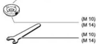
- Retainer mounting flange (for the M 14 grinding spindle with O-ring)
- Grinding-/cutting disc
- Clamping nut



MOUNTING THE PROTECTIVE DEVICES
Before any work on the machine itself, pull out the power plug.
Protective Hood
The protection guard (5) must be mounted when working with grinding or cutting discs. Place the protective hood on the spindle collar. Adjust the position of the protective hood to the requirements of the work process. Clamp down with screw (6). The closed side of the protective hood must always point towards the operator.
Handle
When working with the machine, always mount the handle.
Screw in the handle (2) on the right or left of the machine head depending on the chosen working method.
MOUNTING THE GRINDING TOOLS
Before any work on the machine itself, pull out the power plug.
Use only grinding tools whose allowable speed is at least as high as the idling speed of the machine. Grinding and cutting discs become very hot during use; do not touch them until they have cooled down. Clean the grinder spindle and all parts to be mounted. For clamping and loosening the grinding tools, lock the grinder spindle (4) with the spindle locking button (3). Activate the spindle locking button only when the grinder spindle is at a standstill!
Grinding and Cutting Disc
Observe the dimensions of the grinding discs. The diameter of the hole must fit retainer mounting flange (M 14), (M 10). Do not use any reducers or adapter.
For mounting, see the illustration to the left. Screw on the clamping nut (9) and tighten with the two-hole spanner.

Retainer Mounting Flange for Grinding Spindle (M 14)
An O-ring (plastic part) is inserted in the retainer mounting flange (7) around the spigot. If the O-ring is missing or damaged, it will have to be replaced before the retainer mounting flange is mounted.

After mounting the grinding tool but before switching it on, check that the grinding tool is correctly mounted and that it can turn freely.
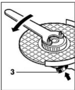
A properly tightened and undamaged quick clamping nut can be loosened by turning the knurled ring counter-clockwise. Never loosen a tightened quick clamping nut with pliers. Instead, use a two-hole spanner. Insert the two-hole spanner as shown in the illustration.
OPERATING INSTRUCTIONS
Clamp down the work piece if it does not • stay in place owing to its own weight.
Do not load the machine so heavily that it • comes to a standstill.
Grinding and cutting discs become very hot • during use; do not touch them until they have cooled down.
Rough Grinding

The best roughing results can be achieved with a 30^ to 40^ approach angle. Move the machine back and forth with moderate pressure. In this manner, the work piece will not overly heat up nor discolour and no ridges will be formed.
Never use a cutting disc for roughing.
Flap Disc
The flap disc (accessory) can be used for working on curved surfaces and profiles (contour sanding).
Flap discs have a considerably higher service life than sanding sheets, a lower noise level and lower sanding temperatures.
ROTATING THE MACHINE HEAD Before any work on the machine itself, pull the power plug.

natural_image
Mechanical component diagram showing a rotating assembly with springs and adjustment knobs (no text or symbols)The machine head can be rotated in 90° steps with respect to the machine housing.
By doing this, the On/Off switch can be brought to a better position for special working situations, e. g., for cutting work with the cutting guide/cutting grinder stand (accessory) or for left-handed persons.
Unscrew the four screws completely. Rotate the machine head carefully and without removing it from the housing bring it to its new position. Screw in the screws again and tighten.
MALMBERGS
- ALLMÄNNA SÄKERHETS- ANVISNINGAR FÖR ELVERKTYG
- WARNING!
- MONTERING AV SKYDDS- ANORDNINGAR
- SUOJIEN KIINNITYS
- Save the manual for future reference.
- 1) Electrical Safety
- 2) Personal Safety
- 3) Power Tool Use and Care
- TOOL SPECIFICATIONS
- INTENDED USE
- FOR YOUR SAFETY
- DESCRIPTION OF PARTS
- MOUNTING THE PROTECTIVE DEVICES
- Protective Hood
- Handle
- MOUNTING THE GRINDING TOOLS
- Grinding and Cutting Disc
- Retainer Mounting Flange for Grinding Spindle (M 14)
- OPERATING INSTRUCTIONS
- Rough Grinding
- Never use a cutting disc for roughing.
- Flap Disc
- ROTATING THE MACHINE HEAD Before any work on the machine itself, pull the power plug.
- MALMBERGS
Brand : Malmbergs
Model : AN846B
Category : Angle Grinder