
FZLS 1005H-E - Log splitter Fieldmann - Free user manual and instructions
Find the device manual for free FZLS 1005H-E Fieldmann in PDF.


| Product Type | Log Splitter |
| Brand | Fieldmann |
| Model | FZLS 1005H-E |
| Splitting Force | 5 tons (44.5 kN) |
| Power Source | Electric, 230 V / 50 Hz |
| Motor Power | 1500 W |
| Max Log Length | 520 mm |
| Max Log Diameter | 250 mm |
| Cycle Time (advance/return) | Approx. 11 s / 8 s |
| Hydraulic Oil Capacity | 3.5 L |
| Dimensions (L x W x H) | 850 x 450 x 620 mm |
| Weight | 52 kg |
| Noise Level | 85 dB(A) |
| Vibration Level | 2.5 m/s² |
| Safety Features | Two-hand operation, safety shield, overload protection |
| Maintenance | Check hydraulic oil level, tighten bolts, clean air filter |
| Cleaning | Wipe with damp cloth; do not use solvents |
| Spare Parts Availability | Pump, seals, motor, wedge, ram |
| Warranty | 2 years |
Frequently Asked Questions - FZLS 1005H-E Fieldmann
User questions about FZLS 1005H-E Fieldmann
0 question about this device. Answer the ones you know or ask your own.
Ask a new question about this device
Download the instructions for your Log splitter in PDF format for free! Find your manual FZLS 1005H-E - Fieldmann and take your electronic device back in hand. On this page are published all the documents necessary for the use of your device. FZLS 1005H-E by Fieldmann.
USER MANUAL FZLS 1005H-E Fieldmann
natural_image
Abstract black-and-white spiral pattern with no text or symbolsFIELDMANN®
Home & Garden Performance
natural_image
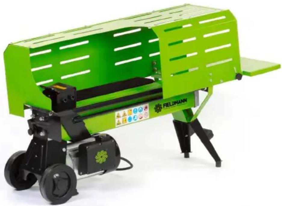
Green industrial machine with black wheels and a transparent cover, labeled 'FIELDMANN' (no visible text or symbols on the device itself)FZLS 1005H-E
English 3-22
Čeština 23-42
Slovenčina 43-62
Magyarul 63-82
Polski 83-110
5T LOG SPLITTER
USER'S MANUAL
TABLE OF CONTENTS
- GENERAL SAFETY INSTRUCTIONS ....4
- SAFETY INSTRUCTIONS....5
- SAFETY WARNINGS & CAUTIONS 8
- APPLICATION CONDITIONS....10
- ELECTRICAL REQUIREMENTS.... 10
- SET UP AND PREPARATION FOR OPERATION ....11
- ASSEMBLY....13
- LOG SPLITTER OPERATION 15
- FREEING A JAMMED LOG 16
- REPLACING HYDRAULIC OIL 17
- TROUBLE SHOOTING .... 18
- SPECIFICATIONS....19
- DISPOSAL....20
- DECLARATION OF CONFORMITY....21
1. GENERAL SAFETY INSTRUCTIONS
Important safety notice
Carefully unpack the product and take care not to throw away any part of the packaging before you find all the parts of the product.
Store the product in a dry place out of reach of children.
Read all warnings and instructions. Not following warnings or instructions may lead to injury by electrical shock, a fire and/or serious injuries.
Packaging
The product is packed in a package that prevents damage during transport. This package is a resource and so can be handed over for recycling.
Operating instructions
Before you start working with the power tool, read the following safety and usage instructions. Understand the operating elements and the correct use of the power tool. Keep the user's manual in a safe place where it can be easily retrieved for future use. Save the original packaging, including the internal packing material, warranty card and proof of purchase receipt, at least for the duration of the warranty. If you need to ship this power tool, pack it in the original cardboard box to ensure maximum protection during shipping or transport (e.g. when moving or when you need to send this power tool for repair to a service centre).

Note: If you hand over the power tool to somebody else, do so together with this user's manual.
Following the instructions in the included user's manual is a prerequisite for the proper use of the power tool. The user's manual also contains operating, maintenance and repair instructions.
The manufacturer takes no responsibility for accidents or damages resulting from not following the instructions in this manual.
2. SAFETY INSTRUCTIONS
ATTENTION!
Acquaint yourself with all warnings and safety instructions and with operation instructions for the power tool.
ATTENTION!
Not adhering to warnings or safety instructions may result in injury by electrical shock, a fire and/or serious injury.
ATTENTION!
Store all warnings and safety instructions in a practical location for future reference.
Note: The term "power tool" in all hereafter provided warnings is defined as an electric power tool powered from the power grid (via a flexible power cord).
Safety in the work area
* Keep the work area tidy and well illuminated. Untidiness and dark locations in the workplace are sources of accidents.
Do not use the power tool in environments where there is a explosion hazard, where there are flammable liquids, gases or dust. The power tool generates sparks which could ignite dust or vapours.
When using the power tool, prevent children and other persons access to the power tool. If you become distracted, you may lose control over the power tool.
Safety when working with power tools
The plug on the flexible power cord must correspond to the power socket outlet. Never modify the plug in any way. Never use any socket adapters with power tools that have a safety earth grounding connection. Plugs that are not damaged by modifications and that correspond to the power socket will limit the danger of injury by electrical shock.
* Prevent your body from coming into contact with grounded objects, such as pipes, central heating radiators, stoves and refrigerators. The risk of injury by electrical shock is greater when your body is connected to the ground.
Do not expose the power tool to rain, dampness or wetness. The entry of water into the power tool increases the danger of injury by electrical shock.
Do not use the flexible power cord for other purposes. Never carry or pull the power tool by its power cord or pull the plug out of the socket by the power cord. Protect the power cord against heat, grease, sharp edges and moving parts. Damaged or tangled power cords increase the danger of injury by electrical shock.
If the power tool is used outdoors, use an extension cord suitable for outdoor use. Using extension cords designed for outdoor use limits the risk of injury by electrical shock.
If you will be using the power tool in a damp environment, use a residual current device (RCD) in the power supply circuit. The use of a residual current device reduces the risk of injury by electrical shock.
Note: The "residual current device" (RCD) may be substituted for by the term "ground fault circuit interrupter" (GFCI) or "earth leakage circuit breaker" (ELCB).
Safety of people
When working with the power tool, always stay alert, watch what you are doing and use common sense. Do not use power tools if you are tired or under the influence of drugs, alcohol or medication. A moment of carelessness when working with power tools may result in serious injury.
Use personal protective aids. Always use eye protection. Use protective aids, e.g. respirator, safety footwear with anti-slip soles, hard head cover or hearing protection appropriately to the work conditions; they reduce the risk of injury to persons.
* Avoid accidentally starting up the power tool. Before connecting to a power source, before connecting the battery, before storage or before carrying the power tool, make sure that the start/stop trigger is in the off position. Carrying the power tool with a finger on the trigger or connecting the power tool's plug with the trigger engaged may cause an accident.
Remove all adjustment tools and spanners before turning on the power tool. An adjustment tool or spanner left attached to a rotating part of the power tool may result in injury to persons.
Only work in locations that you can reach safely. Always maintain a stable stance and balance.
In this way you will have better control over the power tool in unexpected situations.
* Dress in an appropriate manner. Do not wear loose clothing or jewellery. Make sure that your hair, clothing and gloves are at a sufficient distance from moving parts. Loose clothing, jewellery and long hair may become caught in the moving parts.
If there is equipment available for the extraction and collection of dust, make sure that such equipment is connected and used correctly. The use of such equipment may limit the danger posed by the created dust.
Using power tools and their maintenance
Do not overload the power tool. Only use power tools that are appropriate for the work being performed. Appropriate power tools for the given task will do the job better and more safely.
Do not use power tools that cannot be turned on and off with a switch. Any electric power tools that cannot be controlled using a switch are dangerous and must be repaired.
Before adjusting the power tool, before replacing accessories or if you will not be using the power tool, pull the power plug out of the power socket. These preventative safety measures limit the danger of accidentally turning on the power tool.
* When not used, store the power tool out of children's reach and do not permit person not acquainted with the power tool or these instructions to use the power tool. A power tool in the hands of inexperienced users is dangerous.
* Perform maintenance on the tool. Check the adjustment of moving parts and their movement, focus on cracks, broken parts or any other circumstances that may threaten the proper operation of the power tool. If the power tool is damaged, have it repaired before using it again. Many accidents are caused by insufficiently maintained power tools.
Keep cutting power tools clean and sharp. Correctly maintained and sharpened cutting power tools are less likely to get stuck on material or to jam and they are also easier to control.
Use power tools, accessories, working tools, etc. in accordance with these instructions and in such a manner as prescribed for the specific power tool with respect to the given work conditions and the type of work being carried out. Using power tools for tasks other than for which they are designed may lead to dangerous situations.
Service
* Have your power tool repaired by a qualified person that will use original spare parts. In this manner, the same level of safety will be ensured as before the repair of the power tool.
Storage
* only move or store the power tool with the protective cover attached
* carefully clean and perform appropriate maintenance before storing the power tool
* before transporting the power tool, secure it against oil leakage, damage or injury hazard
3. SAFETY WARNINGS & CAUTIONS
| SAFETY WARNINGS & CAUTIONS | SYMBOL AFFIXED TO THE MACHINE |
| UNDERSTAND YOUR LOG SPLITTERRead and understand the owner's manual and labels affixed to the log splitter. Learn its application and limitations as well as the specific potential hazards peculiar to it. |  |
| DRUGS, ALCOHOL AND MEDICATIONDo not operate the log splitter while under the influence of drugs, alcohol, or any medication that could affect your ability to use it properly. | |
| AVOID DANGEROUS CONDITIONSPut the log splitter on a 60 - 75cm high, stable, flat, and level work bench where there is plenty of room for handling, and help the operator stay alert. Bolt the log splitter to the work surface if it tends to slip, walk, or slide.Keep your work area clean and well lighted. Cluttered areas invite injuries.Do not use the log splitter in wet or damp areas or expose it to rain.Do not use it in areas where fumes from paint, solvents or flammable liquids pose a potential hazard. | |
| INSPECT YOUR LOG SPLITTERCheck your log splitter before turning it on. Keep guards in place and in working order. Form a habit of checking to see that keys and adjusting wrenches are removed from tool area before turning it on. Replace damaged, missing or failed parts before using it. |  |
| DRESS PROPERLYDo not wear loose clothing, gloves, neckties or jewelry (rings, wrist watches). They can be caught in moving parts.Protective electrically non conductive gloves and non-skid footwear are recommended when working. Wear protective hair covering to contain long hair, preventing it from get caught in machinery. |   |
| PROTECT YOUR EYES AND FACEAny log splitter may throw foreign objects into the eyes. This can cause permanent eye damage. Always wear safety goggles. Everyday eyeglasses have only impact resistant lenses. They are not safety glasses.Do not put the log splitter on the ground for operations. This is awkward operating position that the operator has to bring his face close to the machine, and thus risks being struck by wood chips or debris. |  |
| EXTENSION CORDSImproper use of extension cords may cause inefficient operation of the log splitter which can result in overheating. Be sure the extension cord is no longer than 10m and its section is no less than 2.5mm2 to allow sufficient current flow to the motor.Avoid use of free and inadequately insulated connections. Connections must be made with protected material suitable for outdoor use. | |
| AVOID ELECTRICAL SHOCKCheck that the electric circuit is adequately protected and that it corresponds with the power, voltage and frequency of the motor. Check that there is a ground connection, and a regulation differential switch upstream.Ground the log splitter. Prevent body contact with grounded surfaces: pipes, radiators, ranges, and refrigerator enclosures.Never open the pushbutton box on the motor. Should this be necessary, contact a qualified electrician.Mark sure your fingers do not touch the plug's metal prongs when plugging or unplugging the log splitter. | |
| KEEP VISITORS AND CHILDREN AWAYThe log splitter must be always operated by one person only. Other people should keep a safe distance from the work area, especially when the log splitter is under operations. Never use another people to help you with freeing jammed log. | 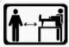 |
| INSPECT YOUR LOGMake sure there are no nails or foreign objects in logs to be split. The ends of the logs must be cut square. Branches must be cut of flush with the trunk. | |
| DON'T OVERREACHFloor must not be slippery.Keep proper footing and balance at all times.Never stand on log splitter. Serious injury could occur if the tool is tipped or if the cutting tools is unintentionally contacted. Do not store anything above or near the log splitter where anyone might stand on the tool to reach them. | |
| AVOID INJURY FROM UNEXPECTED ACCIDENTAlways pay full attention to the movement of the log pusher.Do not attempt to load the log on until the log pusher has stopped.Keep hands out of the way of all moving parts. |  |
| PROTECT YOUR HANDSKeep you hands away from splits and cracks which open in the log; They may close suddenly and crush or amputate your hands.Do not remove jammed logs with you hands. |  |
| DON'T FORCE TOOLIt will do a better and safer job at its design rate. Never try to split logs larger than those indicated in the specifications table. This could be dangerous and may damage the machine.Don't use log splitter for a purpose for which it was not intended. | |
| NEVER LEAVE TOOL RUNNING UNATTENDEDDon't leave tool until it has come to a complete stop. | |
| DISCONNECT POWERUnplug when not in use, before making adjustments, changing parts, cleaning, or working on the log splitter; Consult technical manual before servicing. |  |
| PROTECT THE ENVIRONMENTTake used oil to an authorized collection point or follow the stipulations in the country where the log splitter is used.Do not discharge into drains, soil or water. |  |
| MAINTAIN YOUR LOG SPLITTER WITH CAREKeep the log splitter clean for best and safest performance. | |
| MAKE THE WORKSHOP CHILDPROOFLock the shop. Disconnect master switches. Store the log splitter away from children and others not qualified to use it. |
4. APPLICATION CONDITIONS
This log splitter is a home use model. It is designed for operating under ambient temperatures between +5°C and 40°C and for installation at altitudes no more than 1000m above M.S.L. The surrounding humidity should less than 50% at 40°C. It can be stored or transported under ambient temperatures between -25°C and 55°C.
5. ELECTRICAL REQUIREMENTS
Connect the main leads to a standard 230V ± 10% (50Hz ± Hz) electrical supply which has protection devices of under-voltage, over-voltage, over-current as well as a residual current device (RCD) which maximum residual current rated at 0.03A. Be sure the extension cord is no longer than 10m and the diameter of each line is no less than 2.5mm^2 to allow sufficient current flow to the motor.
6. SET UP AND PREPARATION FOR OPERATION
- Bolt the Support Leg to the Log Splitter, lift the log splitter by the handles at both ends and place it on a 60 – 75cm high, stable, flat and level work surface.
-
Familiarize yourself with the controls and features of this log splitter in the illustrations.
-
Log Pusher
- Work Table
- Wedge
- Lift Handle
- Support Leg
- Log Retaining Plates
- Switch
- Motor
- Pushbutton Box
- Wheels for Minor Moving ONLY.
- Hydraulic Control Lever
- Control Lever Guard
- Bleed Screw
- Oil Drain Bolt w/ Dipstick
- Max Pressure Limiting Screw


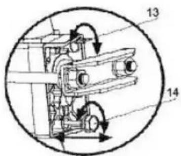
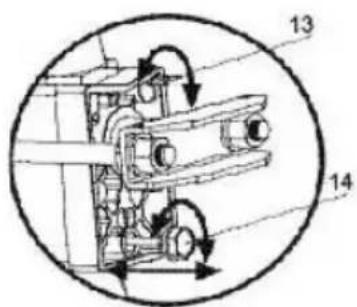
Before operating the log splitter, the Bleed Screw should be loosened by some rotations until air can go in and out of the oil tank smoothly.
Air flow thru the Bleed Screw hole should be detectable during the log splitter is under operations.
Before moving the log splitter, make sure the Bleed Screw is tightened to avoid oil leaking from this point.

FAILED TO LOOSEN THE BLEED SCREW WILL KEEP THE SEALED AIR IN HYDRAULIC SYSTEM BEING COMPRESSED AFTER BEING DECOMPRESSED. SUCH CONTINUOUS AIR COMPRESSION AND DECOMPRESSION WILL BLOW OUT THE SEALS OF THE HYDRAULIC SYSTEM AND CAUSE PERMANT DAMAGE TO THE LOG SPLITTER.
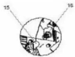
DO NOT ADJUST THE MAX PRESSURE LIMITING SCREW!
Max pressure was set before the log splitter ex work and the max pressure limiting screw is sealed with glue to ensure the log splitter works under pressure no more than rating splitting force. The setting was done by qualified mechanic with professional instruments.
Unauthorized resetting will cause the hydraulic pump fail to output enough splitting pressure or RESULT IN SERIOUS INJURY AS WELL AS DAMAGE TO THE MACHINE.
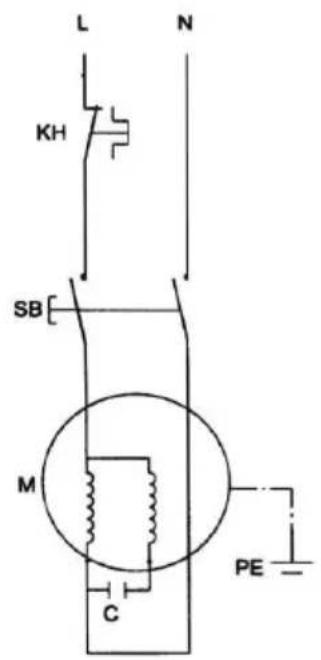
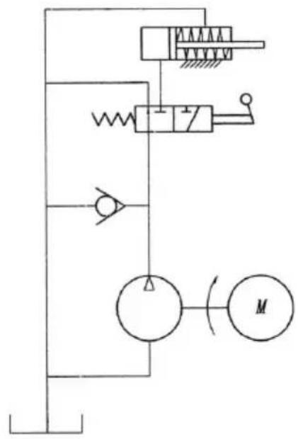
WIRING DIAGRAM PLUMBING DIAGRAM

7. ASSEMBLY

natural_image
Technical line drawing of a mechanical assembly with no visible text or symbolsConnect the log catcher supporting part, supporting leg and work table with screws.
natural_image
Technical line drawing of a mechanical housing or enclosure structure with multiple slatted panels and mounting brackets (no text or symbols)
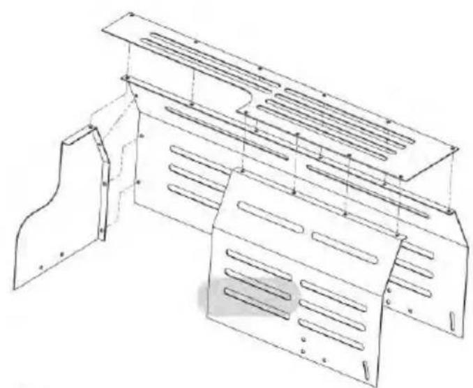
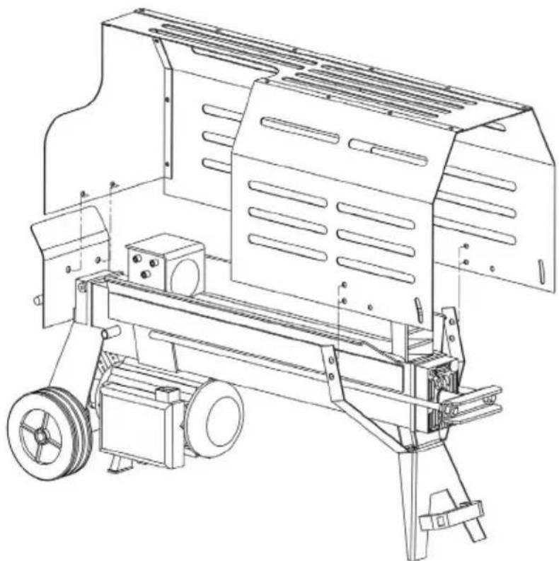
Connect the whole cover with 13 pieces of outside hex bolt M5*10, spring washers ∅5 and gaskets ∅5.
natural_image
Technical line drawing of a mechanical device with wheels and structural panels (no text or symbols)Connect the cover with machine by 2pieces of outside hex bolts M8*16,gasketø8,lock nut M8. 4pieces of outside hex bolts M6*12,gasket ø6,lock nut M6.

natural_image
Technical line drawing of a mechanical device with wheels and a motor (no text or symbols)Then connect the log catcher with the cover by 2 pieces of outside hex bolts M6*12, gasket ø6, lock nut M6 and 2 pieces knobs and gasket ø6.
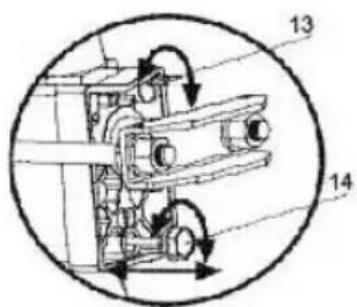
Adjust the height of wood catcher by 2 pieces knob M6.
8. LOG SPLITTER OPERATION
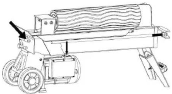
This log splitter is equipped with "ZHB" control system that requires to be operated by both hands of the user – Left hand controls the hydraulic control lever while right hand controls the pushbutton switch. The log splitter will freeze upon absence of either hand. Only after both hands release the controls, the log pusher starts to return backward to the starting position.
Trigger type lock-out device is adopted to avoid accidental Hydraulic Control Lever pushdown. To operate the Hydraulic Control Lever, draw the Trigger backward with the index finger before push the Hydraulic Control Lever forward.
natural_image
Technical line drawing of a mechanical device with rollers and wheels (no text or symbols)
Never force the log splitter for more than 5 seconds by keeping pressure on it to split excessively hard wood.
After this time interval, the oil under pressure will be overheated and the machine could be damaged. For such extremely hard log, rotate it by 90^ to see whether it can be split in a different direction. In any case, if you are not able to split the log, this means that its hardness exceeds the capacity of the machine and thus that log should be discarded to protect the log splitter.
Always set logs firmly on the log retaining plates and work table. Make sure logs will not twist, rock or slip while being split. Do not force the blade by splitting the log on the upper part. This will break the blade or damage the machine.

natural_image
Line drawing of a mechanical device with a diagonal black X mark crossing it, no text or symbols present.Break log in the direction of its growing grain. Do not place log across the log splitter for splitting. It may be dangerous and may seriously damage the machine.
Do not attempt to split 2 pieces of logs at the same time. One of them may fly up and hit you.
9. FREEING A JAMMED LOG
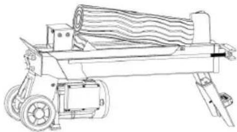
Release both controls.
After the log pusher moves back and completely stops at its starting position, insert a wedge wood under the jammed log.
* Start the log splitter to push the wedge wood to go completely under the jammed one.
* Repeat above procedure with sharper slope wedge woods until the log is completely freed.
Do not try to knock the jammed log off. Knocking about will damage the machine or may launch the log and cause accident.
natural_image
Line drawing of a mechanical device with rollers and wheels (no text or symbols)
natural_image
Line drawing of a mechanical device with a diagonal line crossing through it, no text or symbols present.10. REPLACING HYDRAULIC OIL
Replace the Hydraulic oil in the log splitter after every 150 hours of use. Take following steps to replace it.
Make sure all moving parts stops and the log splitter is unplugged.
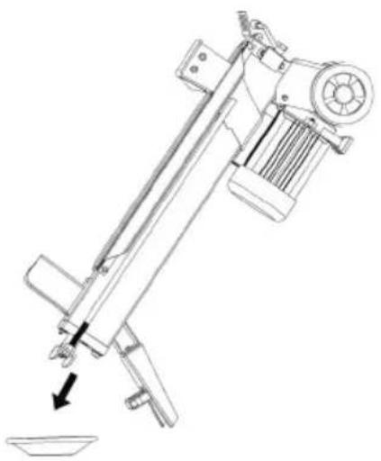
* Unscrew Oil Drain Bolt with Dipstick to remove it.
* Turn the log splitter on the Support Leg side over an 3.5 liters capacity container to drain the hydraulic oil off.
* Turn the log splitter on the the motor side.
* Refill fresh hydraulic oil at the volume as per the hydraulic oil capacity of a particular model indicated in above specifications table.
Clean the surface of Dipstick on the Oil Drain Bolt and put it back into the oil tank while keep the log splitter vertically.
Make sure the level of the refilled oil is just between 2 grooves around the Dipstick.
* Clean the Oil Drain Bolt before thread them back. Make sure they are tightened to avoid leakage before place the log splitter horizontally.
natural_image
Technical line drawing of a mechanical device with a downward arrow indicating motion or force (no text or symbols present)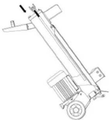
natural_image
Technical line drawing of a mechanical lifting device with wheels and a central shaft (no text or symbols)Periodically check oil level to ensure it is between 2 grooves around the Dipstick. Upon Lower oil level, oil refilling is required.

ATTENTION!
Only use special hydraulic oil for log splitter (for example SHEPPACH HYDRAULIC OIL ISO VG 22, 5 l)
SHELL Tellus 22
MOBIL DTE 11
ARAL Vitam GF 22
BP Energol HLP-HM 22
SHARPENING WEDGE
After using the log splitters for some time, sharpen the wedge of the log splitter using a fine-toothed file and smooth any burrs or crushed area along the cutting edge.
11. TROUBLE SHOOTING
| PROBLEM PROBA | BLE CAUSE REMEDY SUGGESTED | |
| Motor Stops to Start. | Overload Protection Device disengaged to protect the log splitter from being damaged. | Contact a qualified Electrician for opening the Pushbutton Box to engage the Over-load Protection Device inside.* |
| Fails to split logs. Log | is improperly positioned. Refer to "Log Splitter | Operation" section for perfect log loading. |
| The sizes or hardness of the log exceeds the capacity of the machine. | Reduce the log sizes before splitting it on the log splitter. | |
| Wedge cutting edge is blunt. Refer to "Sharpening Wedge" section to sharpen the cutting edge. | ||
| Oil leaks. Locate leak(s) and contact the dealer. | ||
| Unauthorized adjustment was made on Max. Pressure Limiting Screw. Lower max pressure rating was set. | Contact the dealer. | |
| The log pusher moves jerkily, taking unfamiliar noise or vibrating a lot. | Lack of hydraulic oil and excessive air in the hydraulic system. | Check oil level for possible oil refilling. Contact the dealer. |
| Oil leaks around cylinder ram or from other points. | Air sealed in hydraulic system while operating. | Loosen Bleed Screw by 3~4 rotations before operating the log splitter. |
| Bleed Screw is not tightened before moving the log splitter. | Tighten the Bleed Screw up before moving the log splitter. | |
| Oil Drain Bolt with Dipstick is not tight. Tighten the Oil Drain Bolt with Dipstick. | ||
| Hydraulic Control Valve Assembly and / or seal(s) worn. | Contact the dealer. | |
12. SPECIFICATIONS
| Model Number FZLS 1005H-E | ||
| Motor 230V | ~50Hz 2000W IP54 | |
| Log Capacity | Diameter 5 | ~25cm |
| Length 52cm | ||
| Splitting Force 5† | ||
| Hydraulic Oil Capacity 3L | ||
| Overall Size | Length 1320mm | |
| Width 405mm | ||
| Height 650mm | ||
| Weight 53Kg | ||
The diameter of the log is indicative – a small log can be difficult to split when it has knobs or a particularly tough fiber. On the other hand, it may not be difficult to split logs with regular fibers even if its diameter exceeds the max. figure indicated above.
13. DISPOSAL
INSTRUCTIONS AND INFORMATION REGARDING THE DISPOSAL OF USED PACKAGING MATERIALS
Dispose of used packaging material at a site designated for waste in your municipality.

The machine and its accessories are manufactured from various materials, e.g. metal and plastic.
Take damaged parts to a recycling centre. Inquire at the relevant government department.
Changes in the text, design and technical specifications may be made without prior notice and we reserve the right to make these changes.
14. DECLARATION OF CONFORMITY
FAST®
FAST ČR, a.s.
U Sanitasu 1621, 251 01 Řičany, Czech Republic tel.: +420 323 204 111, fax: +420 323 204 110
EU DECLARATION OF CONFORMITY
Product / brand: Electric Log Splitter / FIELDMANN
Type / model: FZLS 1005H – E as factory model HLS5T-52
AC 230 V, 50Hz, 2000W, working force 5 ton, max pressure 20 Mpa, Log size diameter max 250mm, max cutting length 520mm, Class I, IP54, LWA below 70dB(A)
Manufacturer: FAST ČR, a.s.
U Sanitasu 1621, 251 01 Ríčany, Czech Republic VAT no: CZ24777749
This declaration of conformity is issued under the sole responsibility of the manufacturer. Person in charge of completing the technical documentation: FAST ČR, a.s.
The object of the declaration described above is in conformity with the relevant Union harmonization legislation:
Directive MD 2006/42/EC Directive EMC 2014/30/EU
Directive NEOE 2000/14/EC Directive RoHS 2011/65/EU
The relevant harmonized standards and the other technical specifications:
EN 609-1:2017 EN IEC 55014-1:2021
EN 60204-1:2016 EN IEC 55014-2:2021
EN 60204-1:2018 EN IEC 61000-3-2:2019+A1
EN ISO 12100:2010 EN IEC 61000-3-11:2019

Place of issuance: Prague
Date of issuance: 09.11.2022
Name: Petr Uher - Responsible Person Signature:
FAST FAST CR, a.s.
U Sanitásu 1621-251 01 Ričany
tel:+420323204111
ICO: 247 77 248, DIC: CZ 247 77 749
ŠTÍPAČ DŘEVA 5 T
NÁVOD K OBSLUZE
OBSAH
- OBECNÉ BEZPEČNOSTNÍ POKYNY 24
- BEZPEČNOSTNÍ POKYNY 25
- BEZPEČNOSTNÍ VÝSTRAHY A UPOZORNĚNÍ......28
- PODMÍNKY POUŽÍVÁNÍ 30
- POŽADAVKY NA ELEKTRICKÉ PŘIPOJENÍ 30
- INSTALACE A PŘÍPRAVA K PROVOZU....31
- SESTAVENÍ 33
- PROVOZ ŠTÍPAČE DŘEVA....35
- UVOLŇOVÁNÍ UVÍZLÉHO ŠPALKU DŘEVA 36
- VÝMĚNA HYDRAULICKÉHO OLEJE....37
- ŘEŠENÍ PROBLÉMŮ 38
- TECHNICKÉ ÚDAJE 39
- LIKVIDACE 40
- PROHLÁŠENÍ O SHODĚ 41
1. OBECNÉ BEZPEČNOSTNÍ POKYNY
NEPOVOLENÍ ODVĚTRÁVACÍHO ŠROUBU MÁ ZA NÁSLEDEK ZADRŽENÍ VZDUCHU V HYDRAULICKÉM SYSTÉMU, KTERÝ SE STLAČÍ PO UVOLNĚNÍ TLAKU. TAKOVÉ NEUSTÁLÉ STLAČOVÁNÍ VZDUCHU A UVOLŇOVÁNÍ TLAKU VYRAZÍ TĚSNĚNÍ HYDRAULICKÉHO SYSTÉMU A ZPŮSOBÍ TRVALÉ POŠKOZENÍ ŠTÍPAČE DŘEVA.
NEMĚNTE NASTAVENÍ OMEZOVACÍHO ŠROUBU MAXIMÁLNÍHO TLAKU!
7. SESTAVENÍ

natural_image
Technical line drawing of a mechanical assembly with no visible text or symbolsnatural_image
Technical line drawing of a mechanical housing or enclosure with internal compartments and mounting brackets (no text or symbols)
natural_image
Technical line drawing of a mechanical device with wheels and structural panels (no text or symbols)natural_image
Technical line drawing of a mechanical device with wheels and a motor (no text or symbols)natural_image
Technical line drawing of a mechanical device with rollers and wheels (no text or symbols)
natural_image
Line drawing of a mechanical device with a crossed black X mark, no text or symbols presentnatural_image
Line drawing of a mechanical device with rollers and wheels (no text or symbols)
natural_image
Line drawing of a mechanical device with a diagonal line crossing through it, no text or symbols present.10. VÝMĚNA HYDRAULICKÉHO OLEJE
natural_image
Technical line drawing of a mechanical device with a downward arrow indicating force or movement (no text or symbols present)
natural_image
Technical line drawing of a mechanical lifting device with no visible text or symbolsEU DECLARATION OF CONFORMITY
Product / brand: Electric Log Splitter / FIELDMANN
Type / model: FZLS 1005H – E as factory model HLS5T-52
AC 230 V, 50Hz, 2000W, working force 5 ton, max pressure 20 Mpa, Log size diameter max 250mm, max cutting length 520mm, Class I, IP54, LWA below 70dB(A)
Manufacturer: FAST ČR, a.s.
U Sanitasu 1621, 251 01 Říčany, Czech Republic
VAT no: CZ24777749
This declaration of conformity is issued under the sole responsibility of the manufacturer. Person in charge of completing the technical documentation: FAST ČR, a.s.
The object of the declaration described above is in conformity with the relevant Union harmonization legislation:
Directive MD 2006/42/EC Directive EMC 2014/30/EU
Directive NEOE 2000/14/EC Directive RoHS 2011/65/EU
The relevant harmonized standards and the other technical specifications:
EN 609-1:2017 EN IEC 55014-1:2021
EN 60204-1:2016 EN IEC 55014-2:2021
EN 60204-1:2018 EN IEC 61000-3-2:2019+A1
EN ISO 12100:2010 EN IEC 61000-3-11:2019

Place of issuance: Prague
Date of issuance: 09.11.2022
Name: Petr Uher - Responsible Person
Signature:

ŠTIEPAČKA DREVA 5 T
NÁVOD NA OBSLUHU
OBSAH
- VŠEOBECNÉ BEZPEČNOSTNÉ POKYNY 44
- BEZPEČNOSTNÉ POKYNY 45
- BEZPEČNOSTNÉ VÝSTRAHY A UPOZORNENIA 48
- PODMIENKY POUŽÍVANIA....50
- POŽIADAVKY NA ELEKTRICKÉ PRIPOJENIE....50
- INŠTALÁCIA A PRÍPRAVA NA PREVÁDZKU....51
- ZOSTAVENIE....53
- PREVÁDZKA ŠTIEPAČKY DREVA....55
- UVOL'NOVANIE UVIAZNUTÉHO KLÁTA DREVA 56
- VÝMENA HYDRAULICKÉHO OLEJA 57
- RIEŠENIE PROBLÉMOV....58
- TECHNICKÉ ÚDAJE 59
- LIKVIDÁCIA....60
- VYHLÁSENIE O ZHODE....61
1. VŠEOBECNÉ BEZPEČNOSTNÉ POKYNY

NEPOVOLENIE ODVETRÁVACEJ SKRUTKY MÁ ZA NÁSLEDOK ZADRŽANIE VZDUCHU V HYDRAULICKOM SYSTÉME, KTORÝ SA STLAČÍ PO UVOĽNÉNÍ TLAKU. TAKISTO NEUSTÁLE STLÁČANIE VZDUCHU A UVOĽŇOVANIE TLAKU VYRAZÍ TESNENIE HYDRAULICKÉHO SYSTÉMU A SPÔSOBÍ TRVALÉ POŠKODENIE ŠTIEPAČKY DREVA.
NEMEŇTE NASTAVENIE OBMEDZOVACEJ SKRUTKY MAXIMÁLNEHO TLAKU!
ELEKTRICKÁ SCHÉMA HYDRAULICKÁ SCHÉMA

7. ZOSTAVENIE

natural_image
Technical line drawing of a mechanical assembly with no visible text or symbolsnatural_image
Technical line drawing of a mechanical housing or enclosure structure with multiple slatted panels and mounting brackets (no text or symbols)
natural_image
Technical line drawing of a mechanical device with rollers and housing (no text or symbols)Upevnite kryt k stroju 2 skrutkami so šesťhrannou hlavou M8×16, podložkou ∅ 8, poistnou maticou M8. 4 skrutky so šesťhrannou hlavou M6×12, podložka ∅ 6, poistná matica M6.

natural_image
Technical line drawing of a mechanical device with wheels and a motor (no text or symbols)natural_image
Technical line drawing of a mechanical device with rollers and wheels (no text or symbols)
natural_image
Line drawing of a mechanical device with a diagonal line crossing through it, no text or symbols present.natural_image
Line drawing of a mechanical device with rollers and wheels (no text or symbols)
natural_image
Line drawing of a mechanical device with a diagonal line crossing through it, no text or symbols present.10. VÝMENA HYDRAULICKÉHO OLEJA
natural_image
Technical line drawing of a mechanical device with a downward arrow indicating force or motion (no text or symbols present)
natural_image
Technical line drawing of a mechanical lift or lever mechanism (no text or symbols)Pravidelne kontrolujte hladinu oleja a dbajte na to, aby bola medzi 2 drážkami na mierke. Ak je hladina oleja nízko, je nutné doplnit' olej.
POZOR!
U Sanitasu 1621, 251 01 Ríčany, Czech Republic
tel.: +420 323 204 111, fax: +420 323 204 110
EU VYHLASENIE O ZHODE
U Sanitasu 1621, 251 01 Říčany, Czech Republic
VAT no: CZ24777749


A LÉGTELENÍTŐ CSAVAR KILAZÍTÁSÁNAK ELMULASZTÁSA A LEVEGŐ BESZORULÁSÁT EREDMÉNYEZI A HIDRAULIKAI RENDSZERBEN, AMELY A NYOMÁS ELTÁVOLÍTÁSA UTÁN ÖSSZESZORUL. AZ ILYEN FOLYAMATOS LEVEGŐKOMPRESSZIÓ ÉS NYOMÁSCSÖKKENTÉS KINYOMJA A HIDRAULIKAI RENDSZER TÖMÍTÉSÉT, ÉS A RÖNKHASÍTÓ TARTÓS KÁROSODÁSÁT OKOZZA.
NE MÓDOSÍTSA A MAXIMÁLIS NYOMÁST KORLÁTOZÓ CSAVAR BEÁLLÍTÁSÁTI
7. ÖSSZEÁLLÍTÁS

natural_image
Technical line drawing of a mechanical assembly with no visible text or symbolsnatural_image
Technical line drawing of a mechanical housing or enclosure structure with multiple slatted panels and mounting brackets (no text or symbols)
natural_image
Technical line drawing of a mechanical device with wheels and structural panels (no text or symbols)natural_image
Technical line drawing of a mechanical device with wheels and a motor (no text or symbols)natural_image
Technical line drawing of a mechanical device with rollers and wheels (no text or symbols)
natural_image
Line drawing of a mechanical device with a diagonal black X mark crossing it, no text or symbols present.natural_image
Line drawing of a mechanical device with rollers and wheels (no text or symbols)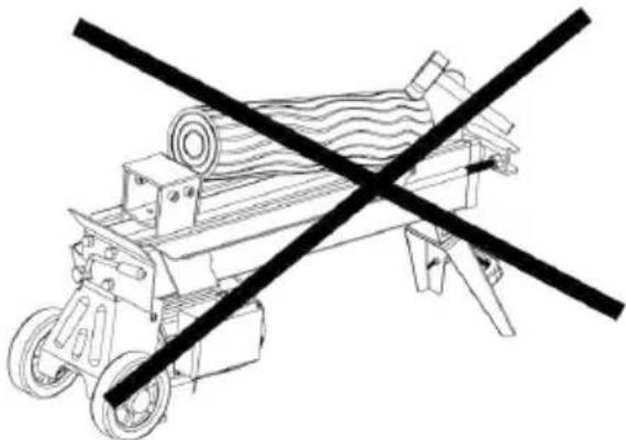
natural_image
Line drawing of a mechanical device with a diagonal line crossing it, no text or symbols present10. HIDRAULIKAOLAJ CSERÉJE
natural_image
Technical line drawing of a mechanical device with a downward arrow indicating force or motion (no text or symbols present)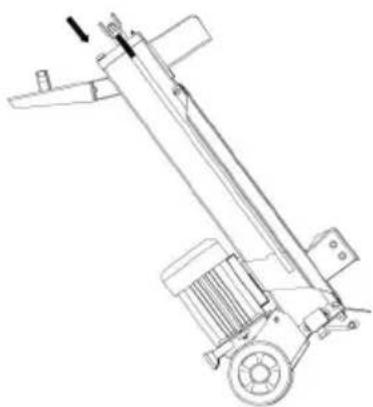
natural_image
Technical line drawing of a mechanical lift or lever mechanism (no text or symbols)U Sanitasu 1621, 251 01 Říčany, Czech Republic
tel.: +420 323 204 111, fax: +420 323 204 110
MEGFELELŐSÉGI NYILATKOZAT
Termék / márka:
Electric Log Splitter/ FIELDMANN
Típus / modell:
FZLS 1005H - E as factory model HLS5T-52
AC 230 V, 50Hz, 2000W, working force 5 ton, max pressure
20 Mpa, Log size diameter max 250mm, max cutting length
520mm, Class I, IP54, LWA below 70dB(A)
Gyártó:
FAST ČR, a.s.
U Sanitasu 1621, 251 01 Říčany, Czech Republic
VAT no: CZ24777749
Directive MD 2006/42/ EC Directive EMC 2014/30/EU
Directive NEOE 2000/14/ EC Directive RoHS 2011/65/EU
és szabványoknak:
EN 609-1:2017 EN IEC 55014-1:2021
EN 60204-1:2016 EN IEC 55014-2:2021
EN 60204-1:2018 EN IEC 61000-3-2:2019+A1
EN ISO 12100:2010 EN IEC 61000-3-11:2019

Kiadva: Prágában
Person
Név: Petr Uher - Responsible

dátum: 9.11.2022
NIEODKRĘCENIE ŚRUBY ODPOWIETRZAJĄCEJ PROWADZI DO ZATRZYMA- NIA POWIETRZA W UKŁADZIE HYDRAULICZNYM, KTÓRE ULEGA SPREŻE- NIU PRZY UWOLNIENIU CIŚNIENIA. TAKIE CIĄGŁE SPREŻANIE POWIETRZA I UWALNIANIE CIŚNIENIA POWODUJE WYBIJANIE USZCZELEK UKŁADU HYDRAULICZNEGO I TRWAŁE USZKODZENIE ŁUPARKI DO DREWNA.
NIE ZMIENIAJ USTAWIEN ŚRUBY OGRANICZAJACEJ MAKSYMALNE CIŚNIENIE!
7. MONTAŻ

natural_image
Technical line drawing of a mechanical assembly with no visible text or symbolsnatural_image
Technical line drawing of a mechanical device with rollers and housing (no text or symbols)natural_image
Technical line drawing of a mechanical device with wheels and a handle (no text or symbols)natural_image
Technical line drawing of a mechanical device with rollers and wheels (no text or symbols)
natural_image
Line drawing of a mechanical device with a diagonal black X mark crossing it, no text or symbols present.natural_image
Line drawing of a mechanical device with rollers and wheels (no text or symbols)
natural_image
Line drawing of a mechanical device with a diagonal black X mark crossing through it (no text or symbols)10. WYMIANA OLEJU HYDRAULICZNEGO
natural_image
Technical line drawing of a mechanical device with a downward arrow indicating force or movement (no text or symbols present)
natural_image
Technical line drawing of a mechanical lift or lever mechanism (no text or symbols)U Sanitasu 1621, 251 01 Ríčany, Czech Republic
tel.: +420 323 204 111, fax: +420 323 204 110
DEKLARACJA ZGODNOŚCI
Produkt / marka:
Electric Lawn Mower/ FIELDMANN
Typ / model:
FZLS 1005H - E as factory model HLS5T-52
AC 230 V, 50Hz, 2000W, working force 5 ton, max pressure 20
Mpa, Log size diameter max 250mm, max cutting length 520mm,
Class I, IP54, LWA below 70dB(A)
Producent:
FAST ČR, a.s.
U Sanitasu 1621, 251 01 Říčany, Czech Republic
VAT no: CZ24777749
Directive MD 2006/42/EC Directive EMC 2014/30/EU
Directive NEOE 2000/14/EC Directive RoHS 2011/65/EU
i norm:
EN 609-1:2017 EN IEC 55014-1:2021
EN 60204-1:2016 EN IEC 55014-2:2021
EN 60204-1:2018 EN IEC 61000-3-2:2019+A1
EN ISO 12100:2010 EN IEC 61000-3-11:2019

natural_image
Abstract black and white spiral pattern with no text or symbolsFIELDMANN®
Home & Garden Performance
Model /Modell /Modelis:
Conditions of guarantee
This product is warranted for the period of 24 months from the date of purchase to the end-user. Warranty is limited to the following conditions. Warranty is referred only to the customer goods using for common domestic use. The claim for service can be applied either at dealer's shop where the product was bought, or at below mentioned authorized service shops. The end-user is obligated to set up a claim immediately when the defects appeared but only till the end of warranty period. The end-user is obligated to cooperate to certify the claiming defects. Only completed and clean (according to hygienic standards) product will be accepted. In case of eligible warranty claim the warranty period will be prolonged by the period from the date of claim application till the date of taking overthe product by end-user, or the date the end-user is obligated to take it over. To obtain the service under this warranty, end-user is obligated to certify his claim with duly completed following documents: receipt, certificate of warranty, certificate of installation...
This warranty is void especially if apply as follows: ■ Defects which were put on sale. ■ Wear-out or damage caused by common use. ■ The product was damaged by unprofessional or wrong installation, used in contrary to the applicable instruction manual, used in contrary to legal enactment and common process of use or used for another purpose which has been designed for. ■ The product was damaged by uncared-for or insufficient maintenance. ■ The product was damaged by dirt, accident of force majeure (natural disaster, fire, flood, ...). ■ Defects on functionality caused by low duality of signal, electromagnetic field interference etc. ■ The product was mechanically damaged (e.g. broken button, fall...). ■ Damage caused by use of unsuitable media, fillings, expendable supplies (batteries) or by unsuitable working conditions (e.g. high temperatures, high humidity, quakes,...). ■ Repair, modification or other failure action to the product by unauthorized person. ■ End-user did not prove enough his right to claim (time and place of purchase). ■ Data on presented documents differs from data on products. ■ Cases when the claiming product can not be identified according to the presented documents (e.g. the serial number or the warranty seal has been damaged).
fasthungary@fasthungary.hu
www.fasthungary.hu
natural_image
Green industrial machine with cutaway blade and control panel (no visible text or symbols)
FIELDMANN®
Home & Garden Performance
- FIELDMANN®
- 5T LOG SPLITTER
- USER'S MANUAL
- TABLE OF CONTENTS
- GENERAL SAFETY INSTRUCTIONS
- Important safety notice
- Packaging
- Operating instructions
- SAFETY INSTRUCTIONS
- ATTENTION!
- Safety in the work area
- Safety when working with power tools
- Safety of people
- Using power tools and their maintenance
- Service
- Storage
- SAFETY WARNINGS & CAUTIONS
- APPLICATION CONDITIONS
- ELECTRICAL REQUIREMENTS
- SET UP AND PREPARATION FOR OPERATION
- DO NOT ADJUST THE MAX PRESSURE LIMITING SCREW!
- ASSEMBLY
- LOG SPLITTER OPERATION
- Never force the log splitter for more than 5 seconds by keeping pressure on it to split excessively hard wood.
- FREEING A JAMMED LOG
- REPLACING HYDRAULIC OIL
- SHARPENING WEDGE
- TROUBLE SHOOTING
- SPECIFICATIONS
- DISPOSAL
- INSTRUCTIONS AND INFORMATION REGARDING THE DISPOSAL OF USED PACKAGING MATERIALS
- DECLARATION OF CONFORMITY
- FAST®
- EU DECLARATION OF CONFORMITY
- ŠTÍPAČ DŘEVA 5 T
- NÁVOD K OBSLUZE
- OBSAH
- OBECNÉ BEZPEČNOSTNÍ POKYNY
- NEMĚNTE NASTAVENÍ OMEZOVACÍHO ŠROUBU MAXIMÁLNÍHO TLAKU!
- SESTAVENÍ
- VÝMĚNA HYDRAULICKÉHO OLEJE
- ŠTIEPAČKA DREVA 5 T
- NÁVOD NA OBSLUHU
- VŠEOBECNÉ BEZPEČNOSTNÉ POKYNY
- NEMEŇTE NASTAVENIE OBMEDZOVACEJ SKRUTKY MAXIMÁLNEHO TLAKU!
- ZOSTAVENIE
- VÝMENA HYDRAULICKÉHO OLEJA
- POZOR!
- EU VYHLASENIE O ZHODE
- ÖSSZEÁLLÍTÁS
- HIDRAULIKAOLAJ CSERÉJE
- MEGFELELŐSÉGI NYILATKOZAT
- NIE ZMIENIAJ USTAWIEN ŚRUBY OGRANICZAJACEJ MAKSYMALNE CIŚNIENIE!
- MONTAŻ
- WYMIANA OLEJU HYDRAULICZNEGO
- DEKLARACJA ZGODNOŚCI
- Model /Modell /Modelis:
- Conditions of guarantee
Brand : Fieldmann
Model : FZLS 1005H-E
Category : Log splitter