
LLMC20 - Modular storage furniture Luxor - Free user manual and instructions
Find the device manual for free LLMC20 Luxor in PDF.


| Product Type | Electronic Device |
| Model | LLMC20 |
| Brand | Luxor |
| Dimensions (W x D x H) | Approx. 300 x 250 x 200 mm |
| Weight | Approx. 2.5 kg |
| Power Supply | 220-240V, 50Hz |
| Power Consumption | 700 W |
| Main Functions | Operation, timer, settings |
| Control Type | Push buttons and dial |
| Display | LED/LCD screen |
| Material | Plastic and metal |
| Color | White/Black |
| Cleaning Instructions | Wipe with a damp cloth; do not immerse |
| Safety Instructions | Keep away from water; unplug when not in use |
| Spare Parts Availability | Contact manufacturer support |
| Reparability | Professional repair recommended |
| Manual Language | English |
Frequently Asked Questions - LLMC20 Luxor
User questions about LLMC20 Luxor
0 question about this device. Answer the ones you know or ask your own.
Ask a new question about this device
Download the instructions for your Modular storage furniture in PDF format for free! Find your manual LLMC20 - Luxor and take your electronic device back in hand. On this page are published all the documents necessary for the use of your device. LLMC20 by Luxor.
USER MANUAL LLMC20 Luxor
Assembly Instructions
Tools Required:
Phillips Head Screwdriver
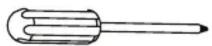
Parts Key
A x1

Charging Cabinet
B x1

Cord Wrap
C x2

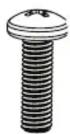
Bolt,
Phillips Head
D x4

Thumbscrew
1 Position cord wrap on the rear of the cabinet, over the corresponding threaded mount holes.


natural_image
Line drawing of a portable oven or refrigerator unit with control panel and side buttons (no text or symbols)2 Insert each bolt into a lock washer, then a flat washer, then use to attach the casters to the Dolly.

natural_image
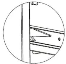
Line drawing of a rectangular electronic device with ventilation slots and ports (no text or symbols)3 Remove the drawer from the bottom/lower cabinet by pressing the release lever on each side of the drawer track.
natural_image
Pure mechanical assembly diagram showing a vertical rod and bracket (no text or symbols)
natural_image
Line drawing of an open industrial machine with internal components and ventilation slots (no text or labels)4 Remove the rubber caps from the top of the cabinet.

natural_image
Simple line drawing of a curved surface with a labeled point D and a dashed vertical line (no text or symbols beyond label)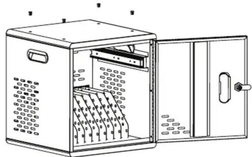
natural_image
Line drawing of an open industrial control cabinet with internal components (no text or symbols)5 Position a second cabinet on top, aligning the threaded mount holes.

natural_image
Line drawing of a two-tiered storage cabinet with open door and ventilation slots (no text or symbols)6 Using the thumbscrews attach the lower Cabinet to the upper Cabinet.

natural_image
Line drawing of an open metal cabinet with internal compartments and ventilation slots (no text or symbols)LUXOR
WORKSPACES
www.luxorworkspaces.com 800-323-4656
LLMCDP
Modular Charging Cabinet -Double Dolly
Assembly Instructions
Tools Required:
Phillips Head Screwdriver

Parts Key

Caster, Locking

Caster,
Non-Locking
C x16
Bolt,
Phillips Head
D x16

Lock Washer
Ex16

Flat Washer
F x8

Thumbscrew
1 Flip the Dolly over and position the casters over the corresponding threaded mount holes.
IMPORTANT: Position the locking casters on the end next to the power strip.

natural_image
Technical line drawing of a mechanical frame with two wheels and labeled points A and B (no text or symbols beyond labels)2 Insert each bolt into a lock washer, then a flat washer, then use to attach the casters to the Dolly.

natural_image
Technical line drawing of a mechanical frame with two wheels and a diagonal guide line (no text or symbols)
3 Using the thumbscrews, attach the Modular Charging Cabinets.
IMPORTANT: Position the Charging Cabinets so the cabinet doors face perpendicular to the edges of the Dolly with the power strips.

natural_image
Technical line drawing of a rectangular electronic device with mounting brackets and internal components (no text or symbols)
natural_image
Mechanical assembly diagram showing a pulley system with labeled component 'F' (no text or symbols beyond label)
natural_image
Line drawing of a two-wheeled industrial machine with wheels and doors (no text or symbols)LUXOR
WORKSPACES
www.luxorworkspaces.com
800-323-4656
LLMCDC
Modular Charging Cabinet
- Dolly Connection Plate
Assembly Instructions
Tools Required:
Phillips Head Screwdriver

* Phillips head bolts come with the Dolly assemblies.
**Thumbscrews come with the Modular Charging Cabinet assemblies.
Parts Key
A x1

natural_image
Technical line drawing of a mechanical component with flanged ends and bolt holes (no text or symbols)Connection Plate
B x4

Caster,
Locking
C x4

Caster,
Non-Locking
D x32E x32

Bolt,
Phillips Head
G x8
Lock Washer

Flat
Washer

Thumbscrew
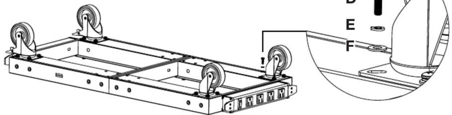
1 Flip the Dollies over, position them end-to-end with the power strips facing out, and position the casters at each corner over the corresponding threaded mount holes.
IMPORTANT: Position at least one set of locking casters on one end. If desired, you can place a locking caster at all four corners.

natural_image
Technical line drawing of a mechanical assembly with two labeled components (B and C), showing structural components and wheel supports (no text or symbols present)2 Position the Connection Plate over the corresponding threaded mount holes where the two Dollies are joined.

natural_image
Technical line drawing of a vehicle chassis frame with wheels and mounting brackets (no text or symbols)3 Insert each bolt into a lock washer, then a flat washer, then use 16 bolts to attach the casters to the Dollies.
natural_image
Technical line drawing of a mechanical frame with two wheels and a separate inset showing labeled components (no text or symbols present)4 Use the remaining 16 bolts to attach Connection Plate to the Dollies.

natural_image
Technical line drawing of a mechanical frame assembly with wheels and mounting holes, plus a close-up detail showing bolted fasteners (no text or symbols)5 Using the thumbscrews, attach the Modular Charging Cabinets.

natural_image
Technical line drawing of a mechanical enclosure or housing with mounting brackets and ventilation slots (no text or symbols)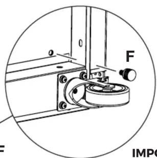
natural_image
Mechanical assembly diagram showing a rotating component with labeled force F and IMPC (no text or symbols beyond labels)
natural_image
Line drawing of a two-wheeled industrial cart with wheels and doors (no text or symbols)IMPORTANT: Position the Charging Cabinets so the cabinet doors face perpendicular to the power strips.
LUXOR
WORKSPACES
www.luxorworkspaces.com
800-323-4656
LLMCPH
Modular Charging
Cabinet – Dolly Handle
Assembly Instructions
Parts Key
B x4

natural_image
Pure mechanical bracket diagram without any text or symbolsHandle

Bolt, Socket Head
C x4

Split Washer
1 Line the handle up with the corresponding threaded mount holes on the sides of the Dolly.
NOTE: While the handle can be attached to either end, it's generally best to attach the handle to the end with the power strip and caster locks.

2 Use the socket head bolts and split washers to attach the handle to the Dolly.

natural_image
Line drawing of a two-wheeled cart with a handle and wheels (no text or symbols)
- Tools Required:
- LUXOR
- LLMCDP
- Modular Charging Cabinet -Double Dolly
- WORKSPACES
- LLMCPH
- Modular Charging
- Cabinet – Dolly Handle
- Assembly Instructions
- Line the handle up with the corresponding threaded mount holes on the sides of the Dolly.
- Use the socket head bolts and split washers to attach the handle to the Dolly.
Brand : Luxor
Model : LLMC20
Category : Modular storage furniture