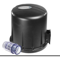
PRO2002403SW - Ventilateur d'air INTERMATIC - Free user manual and instructions
Find the device manual for free PRO2002403SW INTERMATIC in PDF.


| Product Type | Programmable Timer/Switch |
| Brand | Intermatic |
| Model | PRO2002403SW |
| Dimensions (W x H x D) | 4.5 x 2.5 x 1.5 inches |
| Weight | 0.5 lbs |
| Power Supply | 120V AC, 60Hz |
| Maximum Load | 15A / 1800W (Resistive) |
| Supported Voltages | 120V - 277V AC |
| Timer Settings | 7-Day programmable, up to 8 on/off events |
| Display Type | Digital LCD |
| Backup Battery | CR2032 Lithium (included) |
| Operating Temperature | 0°C to 40°C (32°F to 104°F) |
| Mounting Type | In-wall (standard junction box) |
| Wiring | Single-pole or 3-way |
| Certifications | UL Listed, cUL Listed |
| Warranty | 1 year limited |
| Maintenance | Wipe with dry cloth; no liquid cleaners |
| Safety Features | Overload protection, fire-resistant casing |
| Spare Parts Available | Replacement batteries, faceplates |
| Repairability | Non-user serviceable; contact technician |
Frequently Asked Questions - PRO2002403SW INTERMATIC
User questions about PRO2002403SW INTERMATIC
0 question about this device. Answer the ones you know or ask your own.
Ask a new question about this device
Download the instructions for your Ventilateur d'air in PDF format for free! Find your manual PRO2002403SW - INTERMATIC and take your electronic device back in hand. On this page are published all the documents necessary for the use of your device. PRO2002403SW by INTERMATIC.
USER MANUAL PRO2002403SW INTERMATIC
natural_image
Black-and-white photo of a cylindrical mechanical component with a flanged end and internal structure, placed on a textured surface (no text or symbols visible)THIS PAGE INTENTIONALLY LEFT BLANK.
Please read and save these instructions. Read carefully before attempting to assemble, install, operate or maintain the product described. Protect yourself and others by observing all safety information. Failure to comply with instructions could result in personal injury and/or property damage! Retain instructions for future reference.
Description
The Air Blower is designed for outdoor spa applications. It is designed for low noise and a high air flow rate. The unit is UL listed and the motor is protected with a resetting thermal overload device. The blower is designed for permanent electrical connections. This product is designed for residential use only. This product must not be used for commercial applications.
The box contains the following:
- Blower
- Mounting Bracket
• UL Approved Check Valve - Conduit Cover Plate, Gasket, and Screws
- Instruction Manual
Unpacking/Unit Inspection
After unpacking the blower, carefully inspect for any damage that may have occurred during transit. Check for loose, missing or damaged parts. DAMAGE TO THE UNIT DURING TRANSPORTATION IS NOT THE RESPONSIBILITY OF THE MANUFACTURER.
Important Safety Instructions
When installing and using this electrical equipment, basic safety precautions should always be followed.
READ AND FOLLOW ALL INSTRUCTIONS.
Safety Guidelines
This manual contains information that is very important to know and understand. This information is provided for SAFETY and to PREVENT EQUIPMENT PROBLEMS. To help recognize this information, observe the following symbols:
DANGER
Danger indicates an imminently
hazardous situation which, if not avoided, will result in death or serious injury.
WARNING
Warning indicates a potentially
hazardous situation which, if not avoided, COULD result in death or serious injury.
CAUTION
Caution indicates a potentially
hazardous situation which, if not avoided, MAY result in minor or moderate injury.
NOTICE
Notice indicates important
information, that if not followed, may cause damage to equipment.
General Safety Information
CALIFORNIA PROPOSITION 65
WARNING
This product or its power cord may
contain chemicals, including lead, known to the State of California to cause cancer and birth defects or other reproductive harm. Wash hands after handling.
GENERAL
WARNING
To reduce the risk of injury, do not
allow children to use this product unless they are closely supervised at all times.
WARNING
Install blower no less than 1 foot
(305 mm) above the maximum water level to prevent water from contacting electrical equipment. Install in accordance with the installation instructions.
WARNING
Blower is designed for outdoor use.
Install blower at least two feet above the ground in an area free of debris, chemicals, or sprinklers.
ELECTRICAL
WARNING

Disconnect power before attempting to install, service, relocate or perform any maintenance. Tag and disconnect power and lock the fuse box panel to prevent unexpected application of power.
WARNING
Risk of Electric
Shock. Install blower at least 5 feet (1.5 m) from pool / spa water using nonmetallic plumbing.

WARNING
To reduce the risk
of electrical shock, connect the green colored wire inside the electrical box to the grounding terminal of your electrical service or supply with a contig green insulated solid copper or minimum No. 8 AWG (8.4 mm) copper conductor between the and any metal equipment, metal enclosures of electrical equipment, metal water pipe, or conduit v feet (1.5 m) of the unit.

SAVE THESE INSTRUCTIONS.
Installation Guidelines
WARNING
Failure to observe installation
guidelines, could result in death or serious injury.
See Figure 1 for recommended installation diagram.
- Install at least 5 feet (1.5 m) from pool / spa water using nonmetallic plumbing. Install blower no less than 1 foot (305 mm) above the maximum water level to prevent water from contacting electrical equipment. Install in accordance with the installation instructions.
-
The check valve supplied with the unit must be installed in a vertical orientation above the water level in an easily accessible location for serviceability. Take care to orient the check valve with the arrow pointing in the direction of the air flow inside the pipe.
-
Use a separate dedicated 2-inch rigid PVC supply line from the blower to the spa.
REMINDER: Keep your dated proof of purchase for warranty purposes!
Attach it to this manual or file it for safekeeping.
815.675.7000

Mount using rigid PVC pipe. For additional support, use supplied bracket as shown.
Figure 1
Installation Guidelines (Continued)
WARNING
Do not glue the blower to the
supply line. Glue fumes can potentially cause an explosion when the blower starts. Install a 1/4" self-tapping screw to secure the joint if necessary.
WARNING
Do not install blower below
water level. Blower must be at least one foot above the maximum water level.
- Mount blower in a vertical position using vertical rigid PVC pipe as shown in Figure 1. For additional support use supplied bracket as shown in Figure 1. For warm climates, try to locate the blower in a shaded location.
WARNING
If the blower is to be installed more
than 25 ft from the spa, it will be necessary to install a loop that is 1 foot above the water line and as close to the spa as possible (See Figure 1).
WARNING
A loop and a check valve must be
installed at least one foot above the water level when supercharging water jets.
- Verify plumbing is free of leaks before adding water to spa.
- Do NOT install adjustable jets. Adjustable jets can cause excessive back pressure within the unit.
- Hydrotherapy jets naturally aerate when installed correctly. Do not use blower to supplement aeration when jets have been installed incorrectly.
Wiring Guidelines
WARNING
Failure to observe wiring instructions,
could result in death or serious injury.
WARNING
All wiring and electrical
connections must be performed by a qualified electrician. Installations must be in accordance with local and national codes.
- For electrical ratings, see product decal.
-
Check the line voltage to make certain it is correct for the blower being used. Do not attempt to connect 240 VAC to a 120-volt blower; it will damage the blower and void the warranty.
-
Refer to the National Electric Code Guidelines for wire size and to prevent electric shock.
- Refer to the National Electric Code Guidelines for proper selection of wiring conduit and strain relief.
- The blower field-wiring box is designed for non-metallic electrical tubing only. Refer to the National Electric Code Guidelines for proper selection of wiring, and strain relief.
- Be certain to connect the green ground wire supplied with the blower to the ground from your electrical panel.
- Connect remaining line wires individually to the remaining wires in the blower.
- When wiring is complete carefully install gasket and conduit cover plate.
CAUTION
Overheating, short-circuiting and fire
damage will result from inadequate wiring.
Blower Sizing
The number of holes in the seats and floor of the spa can be used to determine the size of the air blower that will be required for your application. See Chart 1 for recommended blower size based on the number and size of holes.
Water Jet Applications
The blower can be used to boost the output of hydrotherapy jets. A venturi fitting is normally incorporated into the jet design. The purpose of the fitting is to allow air to mix with the water in the jet. The venturi fittings can be connected together and then pressurized with air from the blower to greatly increase the jet action.
New Spa Applications
It is important to select a water pump that will supply sufficient flow to the jets. Consult with the jet manufacturer for assistance in selecting a pump or pumps that will accommodate the number of jets desired in the spa. Improper sizing can cause overheating of the pump and blower.
Choose the correct size blower based on the number of water jets in your spa (see Chart 1). See the chart below. Refer to the installation guidelines for additional details.
Winterizing
The blower is designed for outdoor use. There are no special off-season requirements for the blower. In some spa systems it is possible to protect discharge lines from freezing by operating the blower for several minutes with the spa drained. The airflow can be used to purge water from the air lines.
| Blower HP Rating | Total Hole Area Square Inches | Recommended Number of Holes at the Following Hole Diameters 1/8 Inch 3/16 Inch 1/4 Inch | Number of Water Jets |
| 1 HP Blowers | 1.0 | 76 35 20 | 4 to 9 |
| 1.5 HP Blowers | 1.4 | 100 46 26 | 9 to 13 |
| 2 HP Blowers | 1.8 | 150 68 38 | 14 or more |
| Chart 1 |
Notes
Troubleshooting Chart - All repairs must be completed by licensed or certified professionals.
| Symptom Possible Cause(s) Corrective Action(s) Safety Alert | |||
| Blower will not start | 1. Power Off2. Internal blower overload trips3. Brushes worn out4. Nuisance trips | 1. Check electrical connections and fuse box / control panel2. Disconnect power then check for restrictions or blockage in air discharge line3. Replace motor4. It is possible that if the blower is started and stopped repeatedly in a short time period, the thermal overload could interrupt the circuit. Allow the unit to cool and disconnect power. Restart after 5 - 15 minutes (depending on warmth of ambient conditions). | Disconnect power BEFORE taking any corrective action(s) |
| Blower hums but will not run | 1. Rotor locked2. Brushes worn out3. Wrong voltage | 1. Disconnect power then check for debris or foreign object lodged in blower motor2. Replace motor3. Verify voltage is correct for blower | Disconnect power BEFORE taking any corrective action(s) |
| Blower runs but delivers little air | 1. Low voltage2. Blower too small for application3. Check valve installed incorrectly | 1. Check electrical connectionsVerify voltage is correct for blower2. Install additional blowers, or reduce piping restrictions3. Re-orient check valve | Disconnect power BEFORE taking any corrective action(s) |
| Internal blower overload trips | 1. Blocked or restricted air line2. Check valve installed incorrectly | 1. Check for debris or foreign object lodged in discharge line2. Re-orient check valve | Disconnect power BEFORE taking any corrective action(s) |
| Blower runs too slow | 1. Incorrect line voltage2. Incorrect wire size | 1. Check blower voltage requirements, make certain line voltage is correct2. Verify correct wire gage is being used | Disconnect power BEFORE taking any corrective action(s) |
Replacement Parts List
For Replacement Parts, call 815-675-7000 or email customersupport@intermatic.com
Please provide following information:
- Model number
- Serial number (if any)
- Part descriptions and number as shown in parts list

Ref. No. Description Parts Number QTY.
1 Conduit Cover Plate, Gasket, 2 Screws, and Wiring Diagram (Kit) 81008-001 1
2 Blower Housing with Foam Inserts (Kit) 81006-001 1
3 Bracket 28569-001 1
4 Gear Clamp 67111-001 2
5 Motor 1
1 hp 120v 81000-001
1 hp 240v 81003-001
1-1/2 hp 120v 81001-001
1-1/2 hp 240v 81004-001
2 hp 120v 81002-001
2 hp 240v 80002-001
6 Sleeve 15497 1
7 Discharge Housing 28555-001 1
8 8-16 x 3/4 inch Plastite Screw 67007-001 8
9 Check Valve 10116-001 1
LIMITED WARRANTY
For one (1) year from the date of purchase, the manufacturer will repair or replace, at its option, for the original owner any parts of its Blower ("Product") which are found upon examination by the manufacturer to be defective in materials or workmanship. Please call 815-675-7000 for instructions. Be prepared to provide the model number and serial number when exercising this limited warranty. Purchaser must pay all transportation charges on Products or parts submitted for repair or replacement. All non-warranty service charges are the responsibility of the original owner. Failure to pay for non-warranty service charges will void this Limited Warranty. This Limited Warranty does not cover Products that have been damaged as a result of accident, abuse, misuse, neglect, improper installation, improper maintenance or failure to operate in accordance with the manufacturer's written instructions. All maintenance and service must be performed by service agents approved by the manufacturer. Any unauthorized alteration or repairs will void this Limited Warranty.
THERE IS NO OTHER EXPRESS WARRANTY. IMPLIED WARRANTIES, INCLUDING THOSE OF MERCHANTABILITY AND FITNESS FOR A PARTICULAR PURPOSE, ARE LIMITED TO ONE (1) YEAR FROM THE DATE OF PURCHASE. THIS IS THE EXCLUSIVE REMEDY AND ANY LIABILITY FOR ANY AND ALL INDIRECT OR CONSEQUENTIAL DAMAGES OR EXPENSES WHATSOEVER IS EXCLUDED.
Some states do not allow limitations on how long an implied warranty lasts, or do not allow the exclusions or limitations of incidental or consequential damages, so the above limitations might not apply to you. This limited warranty gives you specific legal rights, and you may also have other legal rights which vary from state to state. In no event, whether as a result of breach of contract warranty, tort (including negligence) or otherwise, shall the manufacturer or its suppliers be liable for any special, consequential, incidental or penal damages including, but not limited to loss of profit or revenues, loss of use of the products or any associated equipment, damage to associated equipment, cost of capital, cost of substitute products, facilities, services or replacement power, downtime costs, or claims of buyer's customers for such damages. This Limited Warranty does not include freight charges for equipment or component parts, to and from the factory, services such as maintenance or inspection, repair or damage due to negligence such as freezing conditions, incorrect installation, nor acts of God. It also does not include refrigerant or other expendable materials. The liability of the manufacturer shall not exceed the repair or replacement of defective parts under this Limited Warranty. This Limited Warranty also does not include unnecessary service calls due to erroneous operational reports, external valve positions, or electrical service. If a non-warranty service call is made, and the homeowner is unwilling to pay for the service call, this Limited Warranty will be voided. This Limited Warranty is voided if the product is repaired or altered by any persons or agencies other than those authorized by the manufacturer. This Limited warranty applies only within the continental USA. For warranty outside the continental USA, contact the manufacturer.
You MUST retain your purchase receipt along with this form. In the event you need to exercise a warranty claim, you MUST present a copy of the purchase receipt at the time of service. Please call the manufacturer at 815-675-7000 for service or return authorization and instructions.
DO NOT MAIL THIS FORM TO the manufacturer. Use this form only to maintain your records.
MODEL NO. ____ SERIAL NO. ____ INSTALLATION DATE ____
INTERMATIC INCORPORATED, Libertyville, IL 60048
- Description
- Unpacking/Unit Inspection
- Important Safety Instructions
- READ AND FOLLOW ALL INSTRUCTIONS.
- Safety Guidelines
- DANGER
- WARNING
- CAUTION
- NOTICE
- General Safety Information
- CALIFORNIA PROPOSITION 65
- GENERAL
- ELECTRICAL
- SAVE THESE INSTRUCTIONS.
- Installation Guidelines
- See Figure 1 for recommended installation diagram.
- Installation Guidelines (Continued)
- Wiring Guidelines
- Blower Sizing
- Water Jet Applications
- New Spa Applications
- Winterizing
- Notes
- Replacement Parts List
- For Replacement Parts, call 815-675-7000 or email customersupport@intermatic.com
- Ref. No. Description Parts Number QTY.
- LIMITED WARRANTY
- THERE IS NO OTHER EXPRESS WARRANTY. IMPLIED WARRANTIES, INCLUDING THOSE OF MERCHANTABILITY AND FITNESS FOR A PARTICULAR PURPOSE, ARE LIMITED TO ONE (1) YEAR FROM THE DATE OF PURCHASE. THIS IS THE EXCLUSIVE REMEDY AND ANY LIABILITY FOR ANY AND ALL INDIRECT OR CONSEQUENTIAL DAMAGES OR EXPENSES WHATSOEVER IS EXCLUDED.
Brand : INTERMATIC
Model : PRO2002403SW
Category : Ventilateur d'air