
CR45U40001 - Meuble de rangement informatique CyberPower - Free user manual and instructions
Find the device manual for free CR45U40001 CyberPower in PDF.


| Product Type | Uninterruptible Power Supply (UPS) |
| Model | CR45U40001 |
| Brand | CyberPower |
| Dimensions (H x W x D) | 3.5 in x 17.2 in x 13.5 in (2U rackmount) |
| Weight | 28.6 lbs (13 kg) |
| Input Voltage | 120 VAC, 60 Hz |
| Output Voltage | 120 VAC ± 10% (battery mode) |
| Capacity | 1500 VA / 900 W |
| Battery Type | Sealed lead-acid, replaceable |
| Typical Battery Recharge Time | 4 hours to 90% |
| Outlets | 8 NEMA 5-15R (4 battery backup + 4 surge only) |
| Automatic Voltage Regulation (AVR) | Yes, boosts voltage by 30% or cuts by 20% |
| Surge Protection Rating | 1080 Joules |
| User Interface | LED indicators and audible alarms |
| Communication Ports | USB & serial (DB9) for monitoring |
| Included Cable | USB cable (Type A to B) |
| Operating Temperature | 32°F to 104°F (0°C to 40°C) |
| Cleaning Instructions | Wipe with a dry, soft cloth. Do not use liquids. |
| Safety Precautions | Do not overload; connect to grounded outlet; avoid water exposure. |
| Warranty | 3 years for electronics, 2 years for battery |
| Repairability | User-replaceable battery; other repairs by service center. |
Frequently Asked Questions - CR45U40001 CyberPower
User questions about CR45U40001 CyberPower
0 question about this device. Answer the ones you know or ask your own.
Ask a new question about this device
Download the instructions for your Meuble de rangement informatique in PDF format for free! Find your manual CR45U40001 - CyberPower and take your electronic device back in hand. On this page are published all the documents necessary for the use of your device. CR45U40001 by CyberPower.
USER MANUAL CR45U40001 CyberPower
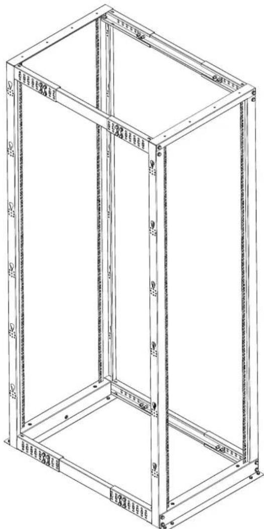
4-Post Open Frame Rack4-Post Op
natural_image
Technical line drawing of a rectangular metal frame structure with mounting holes and internal ribs (no text or symbols)Table of Contents
Parts List 1
Rack Assembly 2
Accessory Installation 4
Leveling Feet 4
Cable Management Rings 4
Grounding Cable 5
Parts List
| No. | Part | Qty |
| Rack Components | ||
| 1 | Left Vertical Rail | 2 |
| 2 | Right Vertical Rail | 2 |
| 3 | Base Bracket | 2 |
| 4 | Corner Section | 8 |
| 5 | Center Section | 4 |
| 6 | Top Bracket | 2 |
| Rack Assembly Hardware | ||
| 7 | M8 Bolt | 48 |
| 8 | M8 Washer | 48 |
| Rack Assembly Tool | ||
| 9 | M8 (13mm) Wrench | 1 |
| 10 | Phillips Screwdriver | 1 |
| Equipment Mounting Hardware | ||
| 11 | M6 Cage Nut | 50 |
| 12 | PVC Cup Washer | 50 |
| 13 | M6 Phillips-Head Screw | 50 |
| Other Hardware and Accessories | ||
| 14 | Cable Management Rings | QtyVaries |
| 15 | Ring Mounting Screw | QtyVaries |
| 16 | Grounding Wires | 2 |
| 17 | M6 Phillips-Head Screw | 4 |
| 18 | Toothed Lock Washer | 4 |
| 19 | Leveling Feet | 4 |


Rack Assembly
Please check packaging contents before starting to assemble.
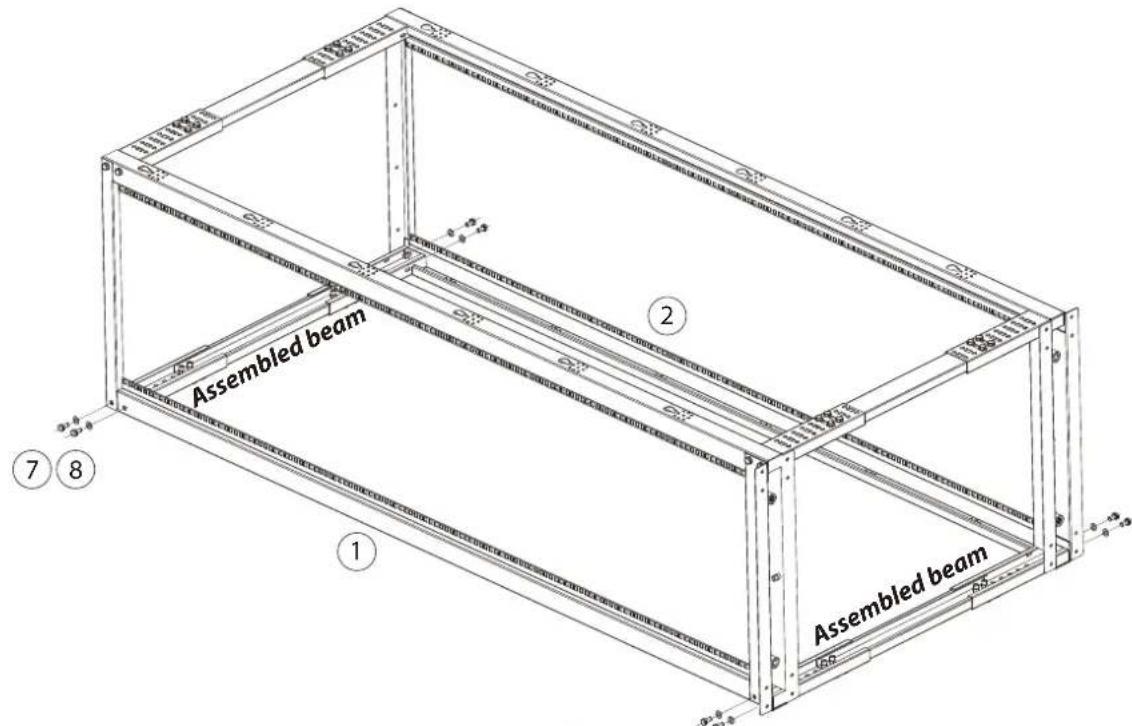
- Assemble the top and bottom beams (4-total) as shown below. Refer to the table below to identify the desired mounting depth (22" to 40" available) and assemble corner and center sections at the corresponding index numbers on each side. For example, for a 33 inch depth, bolt one corner section to index #5 and the other corner section to index #6 onto the center section.

| Mounting Depth | Index Numbers |
| 22 in. | 0 and 0 |
| 23 in. | 1 and 0 |
| 24 in. | 1 and 1 |
| 25 in. | 1 and 2 |
| 26 in. | 2 and 2 |
| 27 in. | 2 and 3 |
| 28 in. | 3 and 3 |
| 29 in. | 3 and 4 |
| 30 in. | 4 and 4 |
| 31 in. | 4 and 5 |
| 32 in. | 5 and 5 |
| 33 in. | 5 and 6 |
| 34 in. | 6 and 6 |
| 35 in. | 6 and 7 |
| 36 in. | 7 and 7 |
| 37 in. | 7 and 8 |
| 38 in. | 8 and 8 |
| 39 in. | 8 and 9 |
| 40 in. | 9 and 9 |
- Using two of the beams assembled in step 1, line up one left and one right vertical rails, followed by a base and top bracket and bolt together using M8 bolts with washers as shown below.
NOTE: To facilitate final assembly, it is recommended to hand-tighten the bolts first. After all parts have been bolted together then tighten them firmly.

- Using the remaining two beams assembled in step 1, line up the other set of left and right vertical rails and fasten them to the base and top brackets as shown below.
Accessory Installation (Optional)
Leveling Feet
Bolt the included leveling feet (4pcs) to the bottom of the base bracket as shown below.
NOTE: Optional caster kit shown is available. Please contact your sales representative for ordering information.

natural_image
Technical line drawing of a mechanical assembly with bolts, rods, and a central component (no text or symbols)Cable Management Rings
Screw the included cable management rings onto the assembled rack as shown below.

Grounding Cable
To tie the assembled rack to the facility's ground, use the grounding wire with the included M6 screw and toothed lock washer. Screw the grounding wire to the pre-installed rivet nut on the inside of the base bracket as shown below.

CyberPower®
CyberPower Systems, Inc.
www.cyberpower.com
For USA and Canada:
4241 12th Ave East, Suite 400
Shakopee, MN 55379
Toll-free: (877) 297-6937
For all other regions:
Please visit our website for local contact information.
- 4-Post Open Frame Rack4-Post Op
- Table of Contents
- Parts List 1
- Rack Assembly 2
- Accessory Installation 4
- Leveling Feet 4
- Cable Management Rings 4
- Grounding Cable 5
- Parts List
- Rack Assembly
- Please check packaging contents before starting to assemble.
- Accessory Installation (Optional)
- Leveling Feet
- Cable Management Rings
- Grounding Cable
- CyberPower®
Brand : CyberPower
Model : CR45U40001
Category : Meuble de rangement informatique