
LA-2202 - Screen AG Neovo - Free user manual and instructions
Find the device manual for free LA-2202 AG Neovo in PDF.


| Product Type | LCD Monitor |
| Screen Size | 21.5 inches (54.6 cm) |
| Resolution | 1920 x 1080 (Full HD) |
| Aspect Ratio | 16:9 |
| Panel Type | TFT LCD |
| Brightness | 250 cd/m² |
| Contrast Ratio | 1000:1 |
| Response Time | 5 ms |
| Viewing Angle (H/V) | 170° / 160° |
| Connectivity | VGA, DVI-D |
| Power Consumption (Typical) | 25 W |
| Standby Power Consumption | < 0.5 W |
| Weight (with stand) | 4.5 kg |
| Dimensions (with stand) | 514 x 380 x 180 mm |
| VESA Mounting | 100 x 100 mm |
| Cleaning Instructions | Wipe with a soft dry cloth. Do not use harsh chemicals. |
| Safety Precautions | Place on stable surface; avoid extreme temperatures and humidity. |
| Power Supply | AC 100-240V, 50/60 Hz |
Frequently Asked Questions - LA-2202 AG Neovo
User questions about LA-2202 AG Neovo
0 question about this device. Answer the ones you know or ask your own.
Ask a new question about this device
Download the instructions for your Screen in PDF format for free! Find your manual LA-2202 - AG Neovo and take your electronic device back in hand. On this page are published all the documents necessary for the use of your device. LA-2202 by AG Neovo.
USER MANUAL LA-2202 AG Neovo
Federal Communications Commission (FCC) Notice (U.S. Only)....3
WEEE 4
PRECAUTIONS
Notice 5
Cautions When Setting Up 5
Cautions When Using....6
Cleaning and Maintenance....7
Notice for the LCD Display....7
CHAPTER 1: PRODUCT DESCRIPTION
1.1 Package Contents 8
1.2 Installation 9
1.2.1 Installing the Stand....9
1.2.2 Adjusting the Tilt 9
1.2.3 Wall Mounting....10
1.3 Overview ...... 11
1.3.1 Front View 11
1.3.3 Rear Vie4 12
CHAPTER 2: MAKING CONNECTIONS
2.1 Connecting the AC Power 13
2.2 Connecting Input Source Signals....13
CHAPTER 3: ON SCREEN DISPLAY MENU
3.1 OSD Menu Tree 14
CHAPTER 4: ADJUSTING THE LCD DISPLAY
4.1 Colour Setting....17
4.2 Picture Setting....18
4.3 OSD Setting 19
4.4 Other Setting 20
4.5 Reset Setting....21
CHAPTER 5: APPENDIX
5.1 Warning Messages....22
5.2 Troubleshooting....23
CHAPTER 6: SPECIFICATIONS
6.1 Display Specifications 24
6.2 Display Dimensions....25
Federal Communications Commission (FCC) Notice (U.S. Only)

This equipment has been tested and found to comply with the limits for a Class B digital device, pursuant to part 15 of the FCC Rules. These limits are designed to provide reasonable protection against harmful interference in a residential installation. This equipment generates, uses and can radiate radio frequency energy and, if not installed and used in accordance with the instructions, may cause harmful interference to radio communications. However, there is no guarantee that interference will not occur in a particular installation. If this equipment does cause harmful interference to radio or television reception, which can be determined by turning the equipment off and on, the user is encouraged to try to correct the interference by one or more of the following measures:
- Reorient or relocate the receiving antenna.
- Increase the separation between the equipment and receiver.
- Connect the equipment into an outlet on a circuit different from that to which the receiver is connected.
- Consult the dealer or an experienced radio/TV technician for help.

Changes or modifications not expressly approved by the party responsible for compliance could void the user's authority to operate the equipment.
Use only an RF shielded cable that was supplied with the display when connecting this display to a computer device.
To prevent damage which may result in fire or shock hazard, do not expose this appliance to rain or excessive moisture.
THIS CLASS B DIGITAL APPARATUS MEETS ALL REQUIREMENTS OF THE CANADIAN INTERFERENCE-CAUSING EQUIPMENT REGULATIONS.

This device complies with Part 15 of the FCC Rules. Operation is subject to the following two conditions: (1) this device may not cause harmful interference, and (2) this device must accept any interference received, including interference that may cause undesired operation.
SAFETY INFORMATION
WEEE
Disposal of Waste Equipment by Users in Private Household in the European Union.

natural_image
Symbol of a trash bin crossed with a diagonal line and a horizontal bar below (no text or labels)This symbol on the product or on its packaging indicates that this product must not be disposed of with your other household waste. Instead, it is your responsibility to dispose of your waste equipment by handing it over to a designated collection point for the recycling of waste electrical and electronic equipment. The separate collection and recycling of your waste equipment at the time of disposal will help to conserve natural resources and ensure that it is recycled in a manner that protects human health and the environment. For more information about where you can drop off your waste equipment for recycling, please contact your local city office, your household waste disposal service or the shop where you purchased the product
For Private Households in the European Union. To help conserve natural resources and ensure the product is recycled in a manner that protects human health and the environment, we would like to bring your attention to the following:
- The crossed-out dustbin on the device or outer packaging indicates the product is compliant with European WEEE (Waste Electrical and Electronic Equipment) Directive
• Always dispose of the old devices separately from household waste - Batteries should be removed beforehand and disposed separately to the right collection system
- You are responsible with regard to the deletion of personal data on old devices before disposal
- Private households can hand in their old devices free of charge
- For more information about where you can drop off your waste equipment for recycling, please contact your local city office, your household waste disposal service or the shop where you purchased the product
PRECAUTIONS
PRECAUTIONS


Symbols used in this manual

This icon indicates the existence of a potential hazard that could result in personal injury or damage to the product.

This icon indicates important operating and servicing information.
Notice
- Read this User Manual carefully before using the LCD display and keep it for future reference.
- The product specifications and other information provided in this User Manual are for reference only. All information is subject to change without notice. Updated content can be downloaded from our web site at www.agneovo.com.
- To protect your rights as a consumer, do not remove any stickers from the LCD display. Doing so may affect the determination of the warranty period.
Cautions When Setting Up
 | Do not place the LCD display near heat sources, such as a heater, exhaust vent, or in direct sunlight. |
 | Do not cover or block the ventilation holes in the housing. |
 | Place the LCD display on a stable area. Do not place the LCD display where it may subject to vibration or shock. |
 | Place the LCD display in a well-ventilated area. |
 | Do not place the LCD display outdoors. |
 | Do not place the LCD display in a dusty or humid environment. |
 | Do not spill liquid or insert sharp objects into the LCD display through the ventilation holes. Doing so may cause accidental fire, electric shock or damage the LCD display. |
Cautions When Using
 | Use only the power cord supplied with the LCD display. |
 | The power outlet should be installed near the LCD display and be easily accessible. |
 | If an extension cord is used with the LCD display, ensure that the total current consumption plugged into the power outlet does not exceed the ampere rating. |
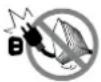 | Do not allow anything to rest on the power cord. Do not place the LCD display where the power cord may be stepped on. |
 | If the LCD display will not be used for an indefinite period of time, unplug the power cord from the power outlet. |
 | To disconnect the power cord, grasp and pull by the plug head. Do not tug on the cord; doing so may cause fire or electric shock. |
 | Do not unplug or touch the power cord with wet hands. |


WARNING:
Unplug the power cord from the power outlet and refer to qualified service personnel under the following conditions:
- When the power cord is damaged.
- If the LCD display has been dropped or the housing has been damaged.
- If the LCD display emits smoke or a distinct odor.
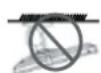
Ceiling mount or mount on any other horizontal surface overhead are not advisable.


WARNING:
Installation in contravention of the instructions may result in undesirable consequences, particularly hurting people and damaging property. Users who have already mounted the display on the ceiling or any other horizontal surface overhead are strongly advised to contact AG Neovo for consultations and solutions to help ensure a most pleasurable and fulfilling display experience.
Cleaning and Maintenance

Do not attempt to service the LCD display yourself, refer to qualified service personnel.
Opening or removing the covers may expose you to dangerous voltage or other risks.
Notice for the LCD Display
In order to maintain the stable luminous performance, it is recommended to use low brightness setting.
Due to the lifespan of the lamp, it is normal that the brightness quality of the LCD display may decrease with time.
When static images are displayed for long periods of time, the image may cause an imprint on the LCD display. This is called image retention or burn-in.
To prevent image retention, do any of the following:
- Set the LCD display to turn off after a few minutes of being idle.
- Use a screen saver that has moving graphics or a blank white image.
- Switch desktop backgrounds regularly.
- Adjust the LCD display to low brightness settings.
- Turn off the LCD display when the system is not in use.
Things to do when the LCD display shows image retention:
- Turn off the LCD display for extended periods of time. It can be several hours or several days.
- Use a screen saver and run it for extended periods of time.
- Use a black and white image and run it for extended periods of time.
There are millions of micro transistors inside the LCD display. It is normal for a few transistors to be damaged and to produce spots. This is acceptable and is not considered a failure.
CHAPTER 1: PRODUCT DESCRIPTION
1.1 Package Contents
When unpacking, check if the following items are included in the package. If any of them is missing or damaged, contact your dealer.

LCD Display

natural_image
Blank whiteboard with a small icon at the bottom (no text or symbols)
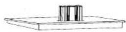

Stand Base


Handle


Quick Start Guide


Warranty Card


Power Cord


HDMI Cable
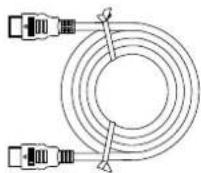
Note:
- Use only the supplied power cord.
- The above pictures are for reference only. Actual items may vary upon shipment.
1.2 Installation
1.2.1 Installing the Stand
- Place the LCD display with the screen side down on a cushioned surface.
- Attach the stand to the LCD display.
a. Press firmly on the base to secure the latches on the base into the slots on the stand.
b. Attach the stand to the base mount.

1.2.2 Adjusting the Tilt
The screen can be adjusted by inclining forward and backward; however, the specific adjustment depends on the specific model of the device. Generally, it may be inclined 5 ± 2irc forward and 15 ± 2irc backward.

PRODUCT DESCRIPTION
1.2.3 Wall Mounting
To wall mount the LCD display, do the following steps:
1. Remove the base stand.
Detach the base from the base mount. Please refer to page 20.
2. Remove the base mount.
a. Place the LCD display with the screen side down on a cushioned surface. b. Push the release button and detach the stand from the base mount.
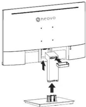
3. Wall mount the LCD display.
Screw the mounting bracket to the VESA holes at the rear of the LCD display.
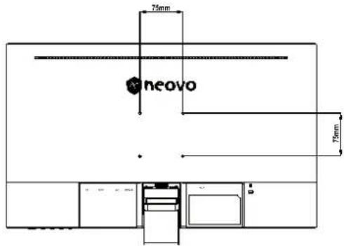
Note: Take measures to prevent the LCD display from falling down and lessen possible injury and damage
to the display in case of earthquakes or other disasters.
- Use only the 75 x 75 mm wall mount kit recommended by AG Neovo. All AG Neovo wall mount kits comply with VESA standard.
- Secure the LCD display on a solid wall strong enough to bear its weight.
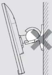
- It is suggested to wall mount the LCD display without tilting it facing downward.
natural_image
Technical line drawing of a mechanical assembly with a circular component and vertical supports (no text or symbols)PRODUCT DESCRIPTION
1.3 Overview
1.3.1 Front View

natural_image
Line drawing of a flat-screen computer monitor with a stand (no text or symbols)1.3.2 Control Buttons

| Button Description | |
| M Button | Pops up the menu/Backs to the previous menu (in case of main menu, exits from the whole menu). |
| E Button • When the menu is activated, press this key to select the function.When the menu closes pressing this button will enter auto adjust, the function is for VGA only. | |
| ▲ Button • When the menu opens, the value is incremented as the right function selection key.When the menu is closed, go to situational mode switch.Hot Key: Press repeatedly to select picture MODE. | |
| ▼ Button • When the menu opens, the progress bar value is decremented as the left function selects the key. | |
| (⏻) | Power button: Powers on/off the monitor. |
| LED indicator light | Long bright (White LED): Normal boot stateFlicker (White LED): Power saving standby state.LED off: Off mode |
1.3.3 Rear Vie4
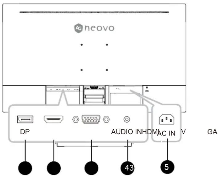
1 DP Input Connect DisplayPort signals input.
2 HDMI Input Connect HDMI signals input.
3 VGA Input Connect VGA signals input.
4 AUDIO IN Connect audio signals input (3.5 mm Stereo Audio Jack).
5 AC IN
AC power input.
CHAPTER 2: MAKING CONNECTIONS
CAUTION:
Make sure that the LCD display is not connected to the power outlet before making any connections. Connecting cables while the power is ON may cause possible electric shock or personal injury.
2.1 Connecting the AC Power
- Connect the power cord to the AC power input at the rear of the LCD display.
- Connect the plug to a power outlet or power supply.

CAUTION:
When unplugging the power cord, hold the power cord by the plug head. Never pull by the cord.
2.2 Connecting Input Source Signals
Input source signals can be connected with either of the following cables:

CHAPTER 3: ON SCREEN DISPLAY MENU
3.1 OSD Menu Tree
| Main menu | Submenu | Third menu Range Description | ||
| Display Brightness 0-100 Adjust display brightness | ||||
ON SCREEN DISPLAY MENU
| Main menu | Submenu | Third menu | Range Description | |
| Mode Standard | ard Set to standard mode | mode | ||
| Cinema Set to Cinema mode | ||||
| FPS Set to FPS mode | ||||
| RTS Set to RTS mode | ||||
| Eye Saver Set to Eye Saver mode | ||||
| Reture Return to the previous menu | ||||
| Exit Exit from the menu | ||||
| Color Temp. | Cool Set to Cool Color temperature | |||
| Warm Set to Warm Color temperature | ||||
| User | Red | 0-100 | Adjust the red output | |
| Green | 0-100 | Adjust the green output | ||
| Blue | 0-100 | Adjust the blue output | ||
| Return | Return to the Color Temp. menu | |||
| Exit | Exit from the whole menu | |||
| Return Return to the previous menu | ||||
| Exit Exit from the menu | ||||
| Aspect | Auto | Picture Aspect | Automatically adjust picture aspect ratio | |
| 16:9 | Set the Picture Aspect to 16:9 | |||
| 4:3 Set the Picture Aspect | to 4:3 | |||
| Return | Return to the previous menu | |||
| Exit | Exit from the menu | |||
| Input | VGA | DisplayPort signals | Set the input source to VGA | |
| HDMI | Set the input source to HDMI | |||
| Return | Return to the previous menu | |||
| Exit | Exit from the menu | |||
| DP Connect DisplayPort signals input. | ||||
ON SCREEN DISPLAY MENU
| Main menu | Submenu | Third menu Range Description | ||
| Other Power | Off On Automatically turn off | after saving function of time to Other menu | power for 1 minute | |
| med switch-off | ||||
| Return Return | ||||
| Exit Exit from the menu | ||||
| Gamma Gam | mar1 Set the Gamma1 | |||
| Gammar2 Set the Gamma2 | ||||
| Return Return to Other menu | ||||
| Exit Exit from the menu | ||||
| Volume 0-100 | Adjust the Volume output | |||
| Adjust | Auto Adjust | Automatically adjust the horizontal/vertical location, focusing and clock of pictures (only for VGA) | ||
| Auto Color | Adjust the white balance of pictures (only for VGA) | |||
| Clock | 0-100 Adjust | st the picture clock to reduce vertical line noise (only for VGA) | ||
| Phase | 0-100 Adjust | st the picture phase to reduce horizontal noise (only for VGA) | ||
| Return Return to Other menu | ||||
| Exit Exit from the menu | ||||
| Return | Return to Other menu | |||
| Exit | Exit from the menu | |||
| Reset | Yes | Reset to factory setup | ||
| No | Exit from this function | |||
| Return | Return to the previous menu | |||
| Exit | Exit from the menu | |||
| Exit | Exit from the menu | |||
Note: Availability of some menu items depend on the input source signal. If the menu is not available, it is disabled and greyed out.
CHAPTER 4: ADJUSTING THE LCD DISPLAY
4.1 Colour Setting
- Press the MENU button to call out the OSD window.
- Press the ◀ or ▶ button to select 🔍 and press the MENU button to enter the Colour menu.

- Press the ◀ or ▶ button to select an option and press the MENU button to enter its submenu.
| Item Function | Operation Range | ||
| Contrast Adjusts | the difference between the black level and the white level. | Press the ◀ or ► button to adjust the value. | 0 to 100 |
| Brightness Adjust | is the luminance of the screen image. | ||
| Color Temp.(Colour Temperature) | Provides several colour adjustment settings. | Press the ◀ or ► button to select the setting. | 930065005500USER |
| Colour temperature can be set to:9300 - Applies a bluish tint for cooler colours.6500 - This is the default colour temperature commonly used for normal lighting conditions.5500 - Applies a reddish tint for warmer colours.USER - This allows users to set the colour temperature by adjusting the red, green, or blue setting according to one's preference.a. Select USER and press the MENU button.b. Press the ◀ or ► button to select the colour you want to adjust. Then press the MENU button to enter its submenu.c. Press the ◀ or ► button to adjust the value (0 ~ 255).Note: Activate Reset to return the colour to its default setting. | |||
| Auto Adjust Automatically optimises image display.Note: This menu option is only available if the input source is VGA. | Press the MENU button to execute the function. | - | |
| Color Adjust Operates the white balance and automatically adjusts the colour settings.Note: This menu option is only available if the input source is VGA. | - | ||
ADJUSTING THE LCD DISPLAY
4.2 Picture Setting
Note: This menu is only available if the input source is VGA.
- Press the MENU button to call out the OSD window.
- Press the ◀ or ▶ button to select □ and press the MENU button to enter the Picture menu.
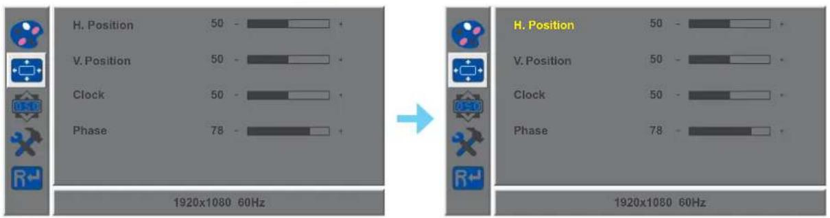
- Press the ◀ or ▶ button to select an option and press the MENU button to enter its submenu.
| Item Function Operation Range | |||
| H. Position (Horizontal Position) | Moves the screen image to the left or right. | Press the ◀ or ► button to adjust the value. | 0 to 100 |
| V. Position (Vertical Position) | Moves the screen image up or down. | ||
| Clock Adjusts the frequency timing to synchronise with the video signal. | |||
| Phase Adjusts the phase timing to synchronise with the video signal. | |||
ADJUSTING THE LCD DISPLAY
4.3 OSD Setting
- Press the MENU button to call out the OSD window.
- Press the ◀ or ▶ button to select OSD and press the MENU button to enter the OSD menu.
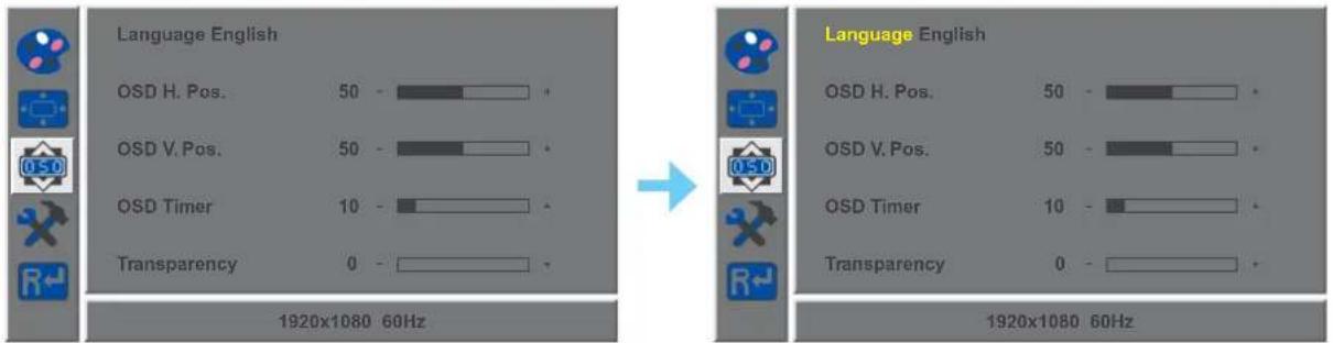
- Press the ◀ or ▶ button to select an option and press the MENU button to enter its submenu.
| Item Function Operation Range | |||
| Language Choose the language used for OSD menus. | Press the ◀ or ► button to select the setting. | EnglishFrançaisDeutschItalianoРусскийSpanishPortuguese日本語한국어繁體中文简体中文Polski | |
| OSD H. Pos.(Horizontal Position) | Moves the OSD window to the left or right of the screen. | Press the ◀ or ► button to adjust the value. | 0 to 100 |
| OSD V. Pos.(Vertical Position) | Moves the OSD window up or down the screen. | ||
| OSD Timer Sets | the length of time (in seconds) the OSD screen is displayed. When the time elapses, the OSD screen is automatically inactivated. | 5 to 60 | |
| Transparency Adjusts the transparency level of the OSD screen. | 0 to 4 | ||
ADJUSTING THE LCD DISPLAY
4.4 Other Setting
- Press the MENU button to call out the OSD window.
- Press the ◀ or ▶ button to select ✗ and press the MENU button to enter the Other menu.

- Press the ◀ or ▶ button to select an option and press the MENU button to enter its submenu.
| Item Function Operation Range | |||
| Mode Selects the | display mode. | Press the ◀ or ► button to select the setting. | PCVIVIDMovie |
| Audio Volume Adjusts the volume level of the built-in speaker. | Press the ◀ or ► button to adjust the value. | 0 to 100 | |
| Signal Source Switches the input source. | Press the ◀ or ► button to select the setting. | VGAHDMIDP | |
| Aspect Ratio | Selects the aspect ratio of the screen image. | 16:9AUTO4:3 | |
| Active Contrast | Automatically adjusts the image contrast according to the scene.Note: If this function is On, Colour >Brightness/Contrast are grey out. | OnOff | |
| Over Drive | Enhance the monitor response time. | OnOff | |
| Anti Blue Light | Enables/Disables the blue light filter function.When enabled, it decreases the amount of blue light displayed on the screen,ensuring users a comfortable viewing experience by reducing eyestrain after long periods of use. | 0 to 100 | |
| ANTI-BURN-IN | ENABLEEnables or disables Anti-Burn-inTM function. | OnOff | |
| INTERVAL (HOURS)Selects the interval time (hour) between activating the Anti-Burn-inTM function. | 4568 | ||
ADJUSTING THE LCD DISPLAY
4.5 Reset Setting
- Press the MENU button to call out the OSD window.
- Press the ◀ or ▶ button to select R← and press the MENU button to enter the Reset menu.
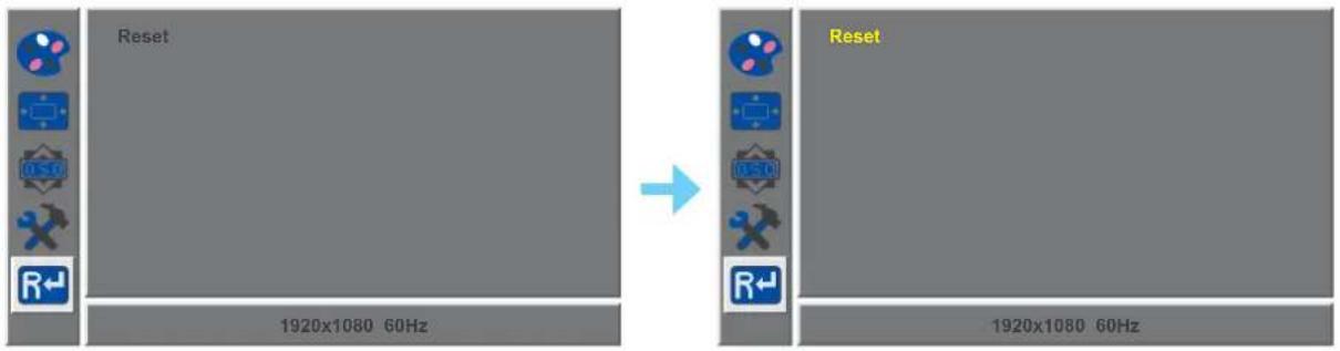
- Press the MENU button to restore your device to factory settings.
CHAPTER 5: APPENDIX
5.1 Warning Messages
When any of these warning messages appear, check the following items.
| Warning Message Cause Solution | ||
 | The LCD display cannot detect the input source signal. | √ Check if the input source is turned ON.√ Check if the signal cable is properly connected.√ Check if any pin inside the cable connector is twisted or broken. |
 | This warning message box will only show when the menu feature setting is changed for the first time. | • Press the ACCEPT button to continue the setting changes, or press the CANCEL button to disable the setting changes.• Note: The operation may vary from different product models. |
5.2 Troubleshooting
| Problems Possible | Cause and Solution |
| The power indicator light is not on | Check if the power is on.Check if the power cord is connected. |
| Impossible plug-and-play · | Check if the function of plug-and-play of the device is compatible with PC.Check if the display card is compatible with the plug-and-play function.Check if the signal line 15 pin d joint bent |
| Dimming picture · Adjust brightness and contrast. | |
| Flickering picture or picture with ripples | There may be electrical appliances or equipment with electronic disturbance. |
| The power indicator light is on (flickering), but the monitor has no pictures. | Check if the PC power is on.Check if the PC display card is inserted properly.Check if the signal cable of the monitor is correctly connected with the PC.Check the signal cable plug of the monitor and make sure every pin has no bending.Observe the indicator light by pressing the Caps Lock key on the PC keyboard and check if the PC is working. |
| Color shortage(red, green and blue) | Check the signal cable of the monitor and make sure every pin has no bending. |
| Picture with color difference(white looks not white) | Adjust RGB color or reselect color temperature. |
| Screen font blur under VGA signal | Select the “E” to automatically adjust the image. |
| Screen color error under VGA signal | Select “Auto color” in OSD to correct under the white output screen. |
CHAPTER 6: SPECIFICATIONS
6.1 Display Specifications
| LA-2402 | ||
| Panel Panel Type LED-Back | lit TFT LCD (VA Technology) | |
| Panel Size 23.8" | ||
| Max. Resolution FHD 1920 x 1080 | ||
| Pixel Pitch 0.275 mm | ||
| Brightness 250 cd/m | 2 | |
| Contrast Ratio 10 | ,000 (DCR) | |
| Viewing Angle (H/V) 178°/178° | ||
| Display Colour 16.7M | ||
| Response Time 5 ms | ||
| Frequency (H/V) H Freq. 30 | kHz-82 kHz | |
| V Freq. | 50 Hz-75 Hz | |
| Input | DisplayPort | 1.2 x 1 |
| HDMI | 1.4 x 1 | |
| VGA | 15-Pin D-Sub x 1 | |
| Audio Audio In | Stereo Audio Jack (35 mm) | |
| Internal Speaker | 1W x 2 | |
| Power | Power Supply | Internal |
| Power Requirements | AC 100-240V, 50/60 Hz | |
| On Mode | 17W (On) | |
| Standby Mode | < 0.5W | |
| Off Mode | < 0.3W | |
| Operating Conditions | Temperature | 0°C-40°C (32°F-104°F) |
| Humidity | 20%-85% (non-condensing) | |
| Storage Conditions | Temperature | -20°C-60°C (-4°F-140°F) |
| Humidity | 5%-95% (non-condensing) | |
| Mounting | VESA FPMPMI | Yes (75 x 75 mm) |
| Stand | Tilt | -5° to 20° |
| Security | Kensington Security Slot | Yes |
| Dimensions | w/ base (W x H x D) 541.9 x 424.2 x 180 | 8 mm (21.3" x 16.7" x 7.1") |
| Packaging (W x H x D) | 602.0 x407.0 x 122.0 mm (23.7" x 16.0" x 4.8") | |
| Weight w/ base | 3.3 kg (7.3 lb) | |
| Packaging 4.5 kg (9.9 lb) | ||
Note: All specifications are subject to change without prior notice.
6.2 Display Dimensions
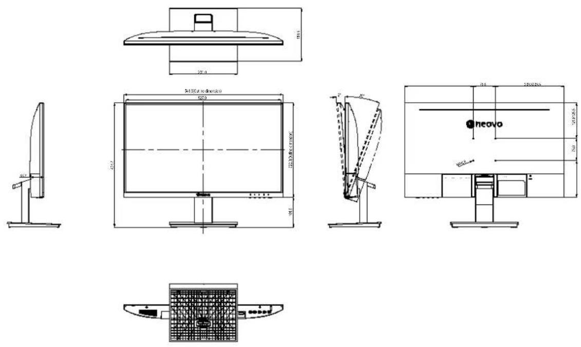
AG Neovo
Company Address: 5F-1, No. 3-1, Park Street, Nangang District, Taipei, 11503, Taiwan.
Copyright © 2022 AG Neovo. All rights reserved.
LA-2402 Eprel registration number: 1144514
LA2420_UM_V010

- PRECAUTIONS
- CHAPTER 1: PRODUCT DESCRIPTION
- CHAPTER 2: MAKING CONNECTIONS
- CHAPTER 3: ON SCREEN DISPLAY MENU
- CHAPTER 4: ADJUSTING THE LCD DISPLAY
- CHAPTER 5: APPENDIX
- CHAPTER 6: SPECIFICATIONS
- Federal Communications Commission (FCC) Notice (U.S. Only)
- SAFETY INFORMATION
- WEEE
- Symbols used in this manual
- Notice
- WARNING:
- Cleaning and Maintenance
- Notice for the LCD Display
- Package Contents
- Note:
- Installation
- Installing the Stand
- Adjusting the Tilt
- PRODUCT DESCRIPTION
- Wall Mounting
- Remove the base stand.
- Remove the base mount.
- Wall mount the LCD display.
- Overview
- Front View
- Control Buttons
- Rear Vie4
- CAUTION:
- Connecting the AC Power
- Connecting Input Source Signals
- OSD Menu Tree
- ON SCREEN DISPLAY MENU
- Colour Setting
- ADJUSTING THE LCD DISPLAY
- Picture Setting
- OSD Setting
- Other Setting
- Reset Setting
- Warning Messages
- Troubleshooting
- Display Specifications
- Display Dimensions
- AG Neovo
Brand : AG Neovo
Model : LA-2202
Category : Screen